EP2551562A2 - Seal For Turbomachine Segments - Google Patents
Seal For Turbomachine Segments Download PDFInfo
- Publication number
- EP2551562A2 EP2551562A2 EP12177149A EP12177149A EP2551562A2 EP 2551562 A2 EP2551562 A2 EP 2551562A2 EP 12177149 A EP12177149 A EP 12177149A EP 12177149 A EP12177149 A EP 12177149A EP 2551562 A2 EP2551562 A2 EP 2551562A2
- Authority
- EP
- European Patent Office
- Prior art keywords
- seal
- sealing
- curved
- interfaces
- holes
- Prior art date
- Legal status (The legal status is an assumption and is not a legal conclusion. Google has not performed a legal analysis and makes no representation as to the accuracy of the status listed.)
- Withdrawn
Links
- 238000007789 sealing Methods 0.000 claims abstract description 412
- 238000001816 cooling Methods 0.000 claims description 69
- 239000002184 metal Substances 0.000 claims description 14
- 229910052751 metal Inorganic materials 0.000 claims description 14
- 239000012530 fluid Substances 0.000 description 47
- 238000005452 bending Methods 0.000 description 33
- 239000011248 coating agent Substances 0.000 description 25
- 238000000576 coating method Methods 0.000 description 25
- 230000008602 contraction Effects 0.000 description 25
- 230000004044 response Effects 0.000 description 15
- 239000000463 material Substances 0.000 description 14
- 239000010408 film Substances 0.000 description 11
- 239000007789 gas Substances 0.000 description 10
- 239000000126 substance Substances 0.000 description 9
- 239000002826 coolant Substances 0.000 description 8
- 238000002485 combustion reaction Methods 0.000 description 7
- 238000004519 manufacturing process Methods 0.000 description 7
- 238000010276 construction Methods 0.000 description 6
- 239000000446 fuel Substances 0.000 description 6
- 230000006870 function Effects 0.000 description 6
- 238000000034 method Methods 0.000 description 6
- 230000003247 decreasing effect Effects 0.000 description 5
- 238000010438 heat treatment Methods 0.000 description 5
- 239000000565 sealant Substances 0.000 description 5
- 239000012720 thermal barrier coating Substances 0.000 description 5
- PXHVJJICTQNCMI-UHFFFAOYSA-N Nickel Chemical compound [Ni] PXHVJJICTQNCMI-UHFFFAOYSA-N 0.000 description 4
- 239000012809 cooling fluid Substances 0.000 description 4
- 230000007797 corrosion Effects 0.000 description 4
- 238000005260 corrosion Methods 0.000 description 4
- 230000006378 damage Effects 0.000 description 4
- 238000009792 diffusion process Methods 0.000 description 4
- 238000005553 drilling Methods 0.000 description 4
- 238000004080 punching Methods 0.000 description 4
- 230000003685 thermal hair damage Effects 0.000 description 4
- 239000010409 thin film Substances 0.000 description 4
- 230000006835 compression Effects 0.000 description 3
- 238000007906 compression Methods 0.000 description 3
- 229910000831 Steel Inorganic materials 0.000 description 2
- 239000000853 adhesive Substances 0.000 description 2
- 230000001070 adhesive effect Effects 0.000 description 2
- 239000000956 alloy Substances 0.000 description 2
- 229910045601 alloy Inorganic materials 0.000 description 2
- 238000005219 brazing Methods 0.000 description 2
- 238000013461 design Methods 0.000 description 2
- 238000010586 diagram Methods 0.000 description 2
- 230000007246 mechanism Effects 0.000 description 2
- 150000002739 metals Chemical class 0.000 description 2
- 239000000203 mixture Substances 0.000 description 2
- 229910052759 nickel Inorganic materials 0.000 description 2
- 230000002093 peripheral effect Effects 0.000 description 2
- 239000010959 steel Substances 0.000 description 2
- 238000003466 welding Methods 0.000 description 2
- 230000008901 benefit Effects 0.000 description 1
- 239000000567 combustion gas Substances 0.000 description 1
- 230000007812 deficiency Effects 0.000 description 1
- 230000000694 effects Effects 0.000 description 1
- 230000006872 improvement Effects 0.000 description 1
Images







Classifications
-
- F—MECHANICAL ENGINEERING; LIGHTING; HEATING; WEAPONS; BLASTING
- F16—ENGINEERING ELEMENTS AND UNITS; GENERAL MEASURES FOR PRODUCING AND MAINTAINING EFFECTIVE FUNCTIONING OF MACHINES OR INSTALLATIONS; THERMAL INSULATION IN GENERAL
- F16J—PISTONS; CYLINDERS; SEALINGS
- F16J15/00—Sealings
- F16J15/02—Sealings between relatively-stationary surfaces
- F16J15/06—Sealings between relatively-stationary surfaces with solid packing compressed between sealing surfaces
- F16J15/08—Sealings between relatively-stationary surfaces with solid packing compressed between sealing surfaces with exclusively metal packing
- F16J15/0887—Sealings between relatively-stationary surfaces with solid packing compressed between sealing surfaces with exclusively metal packing the sealing effect being obtained by elastic deformation of the packing
-
- F—MECHANICAL ENGINEERING; LIGHTING; HEATING; WEAPONS; BLASTING
- F01—MACHINES OR ENGINES IN GENERAL; ENGINE PLANTS IN GENERAL; STEAM ENGINES
- F01D—NON-POSITIVE DISPLACEMENT MACHINES OR ENGINES, e.g. STEAM TURBINES
- F01D11/00—Preventing or minimising internal leakage of working-fluid, e.g. between stages
- F01D11/005—Sealing means between non relatively rotating elements
-
- F—MECHANICAL ENGINEERING; LIGHTING; HEATING; WEAPONS; BLASTING
- F16—ENGINEERING ELEMENTS AND UNITS; GENERAL MEASURES FOR PRODUCING AND MAINTAINING EFFECTIVE FUNCTIONING OF MACHINES OR INSTALLATIONS; THERMAL INSULATION IN GENERAL
- F16J—PISTONS; CYLINDERS; SEALINGS
- F16J15/00—Sealings
- F16J15/02—Sealings between relatively-stationary surfaces
- F16J15/06—Sealings between relatively-stationary surfaces with solid packing compressed between sealing surfaces
- F16J15/064—Sealings between relatively-stationary surfaces with solid packing compressed between sealing surfaces the packing combining the sealing function with other functions
-
- F—MECHANICAL ENGINEERING; LIGHTING; HEATING; WEAPONS; BLASTING
- F05—INDEXING SCHEMES RELATING TO ENGINES OR PUMPS IN VARIOUS SUBCLASSES OF CLASSES F01-F04
- F05D—INDEXING SCHEME FOR ASPECTS RELATING TO NON-POSITIVE-DISPLACEMENT MACHINES OR ENGINES, GAS-TURBINES OR JET-PROPULSION PLANTS
- F05D2240/00—Components
- F05D2240/10—Stators
- F05D2240/11—Shroud seal segments
-
- F—MECHANICAL ENGINEERING; LIGHTING; HEATING; WEAPONS; BLASTING
- F05—INDEXING SCHEMES RELATING TO ENGINES OR PUMPS IN VARIOUS SUBCLASSES OF CLASSES F01-F04
- F05D—INDEXING SCHEME FOR ASPECTS RELATING TO NON-POSITIVE-DISPLACEMENT MACHINES OR ENGINES, GAS-TURBINES OR JET-PROPULSION PLANTS
- F05D2240/00—Components
- F05D2240/55—Seals
Definitions
- the metering holes 56 further improve the seal 50 by controlling any leakage flow between the first and second flows 182 and 184.
- the leakage flow includes a first fluid flow 186 (e.g., air flow) through the first plurality of metering holes 108, and a second fluid flow 188 (e.g., air flow) through the second plurality of metering holes 110.
- These fluid flows 186 and 188 are configured to control the amount of leakage flow from region 182 to region 184, thereby helping to reduce the possibility of leakage along the curved seal interfaces 68, 70, 74, and 76.
- the fluid flows 186 and 188 also provide cooling in the vicinity of the seal 50, e.g., areas 190 and 192.
- the first shaped holes 384 are chevron-shaped or V-shaped
- the second shaped holes 386 are diamond-shaped
- the third shaped holes 388 are X-shaped.
- the chevron-shaped holes 384 may be disposed in the outermost rows 374 and 376, and may be specifically designed to increase cooling (e.g., impingement cooling and/or film cooling) of the seal regions 130 and 132.
- the diamond-shaped holes 386 and X-shaped holes 388 may be configured to meter the leakage flow and/or provide central cooling of the seal 50.
- the holes 56 e.g., 384, 386, and 388) may have uniform or non-uniform angles, shapes, sizes, or other characteristics.
- the illustrated configuration 370 may be selected to meter the leakage flow and increase cooling of the seal 50, the seal regions 130 and 132, or the segments 120 and 122.
- the first shaped holes 400 are triangular holes
- the second shaped holes 402 are circular holes.
- the triangular holes 400 may be disposed in the outermost rows 394 and 396, and may be specifically designed to increase cooling (e.g., impingement cooling and/or film cooling) of the seal regions 130 and 132.
- the centrally located circular holes 402 may be configured to meter the leakage flow and/or provide central cooling of the seal 50.
- the holes 56 e.g., 400 and 402 may have uniform or non-uniform angles, shapes, sizes, or other characteristics.
- the illustrated configuration 390 may be selected to meter the leakage flow and increase cooling of the seal 50, the seal regions 130 and 132, or the segments 120 and 122.
- FIG. 14 is a partial cross-sectional side view of the two-piece seal 50 of FIGS. 2-12 , taken along line 13-13 of FIG. 6 , illustrating an embodiment of a metering hole 56 having a conical shape 430 (e.g., a conical metering hole) of a variable diameter 432. Similar to the embodiment of FIG. 13 , a centerline 434 of the conical metering hole 430 is disposed at a perpendicular angle 436 relative to a surface 438 of the seal 50. In other embodiments, the conical metering hole 430 may be oriented at another angle 436, such as approximately 5 to 60, 10 to 45, or 15 to 30 degrees.
- the illustrated embodiment of the seal 550 is made with first and second pieces 552 and 554 coupled together at the intermediate portion 558.
- the first piece 552 includes a first plate 596 having a first intermediate plate portion 598 disposed between opposite curved end plate portions 600 and 602, wherein the curved end plate portion 600 includes the curved sealing interface 568, and the curved end plate portion 602 includes the curved sealing interface 582.
- the second piece 554 includes a second plate 604 having a first intermediate plate portion 606 disposed between opposite curved end plate portions 608 and 610, wherein the curved end plate portion 608 includes the curved sealing interface 570, and the curved end plate portion 610 includes the curved sealing interface 584.
- the metering holes 556 are angled away from one another toward the opposite segments 120 and 122 and/or associated seal regions 130 and 132.
- the fluid flows 668 and 670 may be angled to flow into the seal regions 130 and 132 to help cool the side walls 138, 140, 146, and 148 and the curved sealing interfaces 570 and 584 of the seal 550.
- the cooling fluid flows 668 and 670 may protect the seal 550 and/or walls 138, 140, 146, and 148 from any thermal damage, wear, or the like.
- the cooling flows 668 and 670 also may serve as shielding fluid flows to reduce chemical attack, corrosion, or other damage to the seal 550 caused by the second fluid flow 184.
- the metering holes 556 also may have a variety of angles, shapes, and configurations configured to control the leakage flow and cooling. As illustrated in FIG. 20 , the first plurality of metering holes 620 are disposed at the angle 624 relative to the longitudinal axis 618, while the second plurality of metering holes 622 are disposed at the angle 626 relative to the longitudinal axis 618. These angles 624 and 626 may be approximately 0 to 90, 20 to 70, 30 to 60, or 40 to 50 degrees, or any other suitable angle. Embodiments of the metering holes 620 and 622 may have angles 624 and 626 of approximately 10, 20, 30, 40, 50, or 60 degrees, for example.
- FIG. 21 is a perspective view of an embodiment of a seal 750 formed from a single piece 752 having a plurality of metering holes 756.
- the seal 750 includes an intermediate portion 758 and first and second sealing end portions 760 and 762 inwardly curving to define c-shaped ends 764 and 766 on opposite sides of the intermediate portion 758, yielding a seal 750 having an overall s-shape.
- the first sealing end portion 760 having the c-shaped end 764 has curved sealing interfaces 768 and 770 disposed opposite from one another about a first space 772.
- the shape or geometry of the seal 750 also may improve the sealing effectiveness of the seal 750, particularly in environments subject to high temperatures, vibration, motion, and thermal expansion and contraction.
- the intermediate plate portion 788 of the plate 786 is substantially flat and tilted with respect to a longitudinal axis 784, although other embodiments of the intermediate plate portion 788 may have a wavy shape as discussed in further detail below.
- the intermediate plate portion 788 may function as a pivot point, axis of rotation, or axis of bending for the curved end plate portions 790 and 792 of the plate 786.
- the c-shaped ends 764 and 766 and the intermediate portion 758 may be described as forming an s-shaped seal 750, such as a spring-loaded s-shaped seal 750.
- the c-shaped ends 764 and 766 also may serve as rotational joints, pivot joints, or cam members, thereby enabling rotational motion along sealing surfaces.
- the curved sealing interfaces 768 and 770 are configured to enable rotation of the sealing end portion 760 along a first sealing region, while the curved sealing interfaces 774 and 776 are configured to enable rotation of the second sealing end portion 762 along a second sealing region.
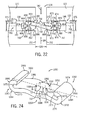
- FIG. 22 is a cross-sectional side view of an embodiment of the one-piece seal 750 of FIG. 21 mounted between adjacent segments 120 and 122 of a turbomachine 124, e.g., the turbine system 10, similar to the embodiments of FIGS. 3 and 19 .
- the adjacent segments 120 and 122 may be disposed side-by-side in the axial direction 38, the radial direction 40, or the circumferential direction 42 with an intermediate gap or space 126.
- the gap 126 may have a width 128 between the adjacent segments 120 and 122.
- the second sealing end portion 762 includes the c-shaped end 766 with the curved sealing interfaces 774 and 776, which are configured to deflect toward and away from one another as indicated by arrow 868, thereby providing biasing forces or spring forces 870 and 872 against the side walls 146 and 148.
- the curved sealing interfaces 774 and 776 may be compressed together between the side walls 146 and 148, such that the curved sealing interfaces 774 and 776 maintain contact despite vibration or motion.
- the curved sealing interfaces 774 and 776 are also frictionally seated along the side walls 146 and 148 via respective frictional forces 874 and 876.
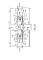
- FIG. 25 is a cross-sectional side view of an embodiment of the one-piece seal 1050 of FIG. 24 mounted between adjacent segments 120 and 122 of a turbomachine 124, e.g., the turbine system 10, similar to the embodiments of FIGS. 3 , 19 , and 22 .
- the adjacent segments 120 and 122 may be disposed side-by-side in the axial direction 38, the radial direction 40, or the circumferential direction 42 with an intermediate gap or space 126.
- the gap 126 may have a width 128 between the adjacent segments 120 and 122.
- FIG. 27 is a cross-sectional side view of an embodiment of a one-piece seal 1350 similar to the seal 1050 of FIGS. 24-26 , illustrating various dimensions of the seal 1350.
- the seal 1350 includes a wavy intermediate portion 1352 curving alternatively in opposite directions, and first and second sealing end portions 1354 and 1356 inwardly curving to define c-shaped ends 1358 and 1360 on the same side of the intermediate portion 1352.
- the first sealing end portion 1354 having the c-shaped end 1358 has curved sealing interfaces 1362 and 1364 disposed opposite from one another about a first space 1366.
- the second sealing end portion 1356 having the c-shaped end 1360 has curved sealing interfaces 1368 and 1370 disposed opposite from one another about a second space 1372.
- the wavy intermediate portion 1352 and the opposite c-shaped ends 1358 and 1360 substantially improve the performance of the seal 1350 in environments subject to high temperatures, vibration, motion, and thermal expansion and contraction.
- the curved sealing interfaces 1368 and 1370 may be compressed together between the side walls 1468 and 1470, such that the curved sealing interfaces 1368 and 1370 maintain contact despite vibration or motion.
- the curved sealing interfaces 1368 and 1370 are also configured to pivot or rotate relative to the side walls 1468 and 1470 as indicated by rotational arrows 1500 and 1502. As discussed in detail above with reference to FIG. 4 , the rotational motion 1500 and 1502 along the side walls 1468 and 1470 may result from a bending or bowing of the spring 1350.
Landscapes
- Engineering & Computer Science (AREA)
- General Engineering & Computer Science (AREA)
- Mechanical Engineering (AREA)
- Turbine Rotor Nozzle Sealing (AREA)
- Structures Of Non-Positive Displacement Pumps (AREA)
Abstract
Description
- The subject matter disclosed herein relates to seals, and more specifically, to seals disposed between segments of a turbomachine.
- A variety of turbomachines, such as turbines and compressors, may include seals disposed between segments. For example, a gas turbine may include stationary segments arranged circumferentially about a rotor, which includes turbine blades. Unfortunately, the segments may experience thermal expansion and contraction, vibration, bending, and other forces, which can reduce the effectiveness of intermediate seals. Furthermore, the seals may experience substantial pressure differences between different fluid flows, such as a hot gas flow driving the turbine blades and an air flow cooling the segments. As a result, the seals may experience uncontrolled amounts of leakage, which can reduce performance and reliability of the turbomachine (e.g., gas turbine). Accordingly, a seal is needed to address one or more of these deficiencies of existing seals.
- Certain embodiments commensurate in scope with the originally claimed invention are summarized below. These embodiments are not intended to limit the scope of the claimed invention, but rather these embodiments are intended only to provide a brief summary of possible forms of the invention. Indeed, the invention may encompass a variety of forms that may be similar to or different from the embodiments set forth below.
- In a first aspect, the present invention resides in a system including a seal having a first sealing end portion, a second sealing end portion, and an intermediate portion between the first and second sealing end portions, wherein the seal has at least one metering hole configured to control a leakage flow across the seal.
- In a second aspect, the invention resides in a system including a turbomachine seal having a first sealing end portion having a first and second curved sealing interface disposed opposite from one another about a first space, and the first and second curved sealing interfaces are configured to resiliently deflect toward and away from one another. The turbomachine seal also includes a second sealing end portion having a third and fourth curved sealing interface disposed opposite from one another about a second space, and the third and fourth curved sealing interfaces are configured to resiliently deflect toward and away from one another. The turbomachine seal also includes an intermediate portion extending between the first and second sealing end portions.
- In a third aspect, the invention resides in a system including a turbomachine seal having a first plate having a first curved sealing interface, a second curved sealing interface, and a first intermediate portion extending between the first and second curved sealing interfaces. The turbomachine seal also includes a second plate having a third curved sealing interface, a fourth curved sealing interface, and a second intermediate portion extending between the third and fourth curved sealing interfaces. The first and second intermediate portions of the turbomachine seal are coupled together. Furthermore, the first and third curved sealing interfaces are configured to resiliently deflect toward and away from one another about a first space, and the second and fourth curved sealing interfaces are configured to resiliently deflect toward and away from one another about a second space. Also, the first and second plates of the turbomachine seal have different coefficients of thermal expansion to cause thermal bending of the turbomachine seal in response to different degrees of thermal expansion of the first and second plates.
- Embodiments of the present invention will now be described, by way of example only, with reference to the accompanying drawings in which:
-
FIG. 1 is a block diagram of a turbine system having one or more seals in accordance with certain embodiments; -
FIG. 2 is a perspective view of an embodiment of a two-piece seal with a plurality of metering holes, wherein opposite ends of the seal are inwardly curving to define opposite U-shaped ends; -
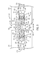
FIG. 3 is a cross-sectional side view of an embodiment of the two-piece seal ofFIG. 2 mounted between adjacent segments of a turbomachine; -
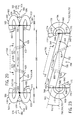
FIG. 4 is a cross-sectional side view of an embodiment of the two-piece seal ofFIG. 2 mounted between adjacent segments of a turbomachine, illustrating behavior of the seal in response to a thermal gradient; -
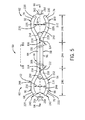
FIG. 5 is a cross-sectional side view of an embodiment of the two-piece seal ofFIG. 2 , illustrating various dimensions of the seal; -
FIG. 6 is a top view of the two-piece seal ofFIGS. 2-5 , taken along line 6-6 ofFIG. 5 , illustrating an embodiment of the metering holes in a staggered configuration of equally sized circular holes; -
FIG. 7 is a top view of the two-piece seal ofFIGS. 2-5 , taken along line 6-6 ofFIG. 5 , illustrating an embodiment of the metering holes in a circular configuration of equally sized circular holes; -
FIG. 8 is a top view of the two-piece seal ofFIGS. 2-5 , taken along line 6-6 ofFIG. 5 , illustrating an embodiment of the metering holes in a multi-row configuration of differently sized circular holes; -
FIG. 9 is a top view of the two-piece seal ofFIGS. 2-5 , taken along line 6-6 ofFIG. 5 , illustrating an embodiment of the metering holes in a single row configuration of equally sized circular holes; -
FIG. 10 is a top view of the two-piece seal ofFIGS. 2-5 , taken along line 6-6 ofFIG. 5 , illustrating an embodiment of the metering holes in a multi-row configuration of differently shaped holes (e.g., elliptical, square, and rectangular holes); -
FIG. 11 is a top view of the two-piece seal ofFIGS. 2-5 , taken along line 6-6 ofFIG. 5 , illustrating an embodiment of the metering holes in a multi-row configuration of differently shaped holes (e.g., chevron-shaped, diamond-shaped, and X-shaped holes); -
FIG. 12 is a top view of the two-piece seal ofFIGS. 2-5 , taken along line 6-6 ofFIG. 5 , illustrating an embodiment of the metering holes in a multi-row configuration of differently shaped holes (e.g., triangular and circular holes); -
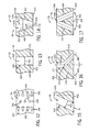
FIG. 13 is a partial cross-sectional side view of the two-piece seal ofFIGS. 2-12 , taken along line 13-13 ofFIG. 6 , illustrating an embodiment of one of the metering holes having a cylindrical shape of a constant diameter at a perpendicular angle; -
FIG. 14 is a partial cross-sectional side view of the two-piece seal ofFIGS. 2-12 , taken along line 13-13 ofFIG. 6 , illustrating an embodiment of one of the metering holes having a conical shape of a variable diameter; -
FIG. 15 is a partial cross-sectional side view of the two-piece seal ofFIGS. 2-12 , taken along line 13-13 ofFIG. 6 , illustrating an embodiment of one of the metering holes having a cylindrical shape of a constant diameter at a non-perpendicular angle; -
FIG. 16 is a partial cross-sectional side view of the two-piece seal ofFIGS. 2-12 , taken along line 13-13 ofFIG. 6 , illustrating an embodiment of one of the metering holes having a forked path (e.g., Y-shaped split path); -
FIG. 17 is a partial cross-sectional side view of the two-piece seal ofFIGS. 2-12 , taken along line 13-13 ofFIG. 6 , illustrating an embodiment of one of the metering holes having a forked path (e.g., V-shaped split path); -
FIG. 18 is a perspective view of an embodiment of a two-piece seal with a plurality of metering holes, wherein opposite ends of the seal are outwardly curving to defme opposite W-shaped ends; -
FIG. 19 is a cross-sectional side view of an embodiment of the two-piece seal ofFIG. 18 mounted between adjacent segments of a turbomachine; -
FIG. 20 is a cross-sectional side view of an embodiment of the two-piece seal ofFIG. 18 , illustrating various dimensions of the seal; -
FIG. 21 is a perspective view of an embodiment of a one-piece seal with a plurality of metering holes, wherein opposite ends of the seal curve in opposite directions to define an S-shaped geometry; -
FIG. 22 is a cross-sectional side view of an embodiment of the one-piece seal ofFIG. 21 mounted between adjacent segments of a turbomachine; -
FIG. 23 is a cross-sectional side view of an embodiment of the one-piece seal ofFIG. 21 , illustrating various dimensions of the seal; -
FIG. 24 is a perspective view of an embodiment of a one-piece seal with a plurality of metering holes, wherein the seal includes an intermediate wavy portion and opposite curved end portions (e.g., U-shaped end portions); -
FIG. 25 is a cross-sectional side view of an embodiment of the one-piece seal ofFIG. 24 mounted between adjacent segments of a turbomachine; -
FIG. 26 is a cross-sectional side view of an embodiment of the one-piece seal ofFIG. 24 , illustrating various dimensions of the seal; -
FIG. 27 is a perspective view of an embodiment of a one-piece seal without metering holes, wherein the seal includes an intermediate wavy portion and opposite curved end portions (e.g., U-shaped end portions); and -
FIG. 28 is a cross-sectional side view of an embodiment of the one-piece seal ofFIG. 27 mounted within a seal region. - One or more specific embodiments of the present invention will be described below. In an effort to provide a concise description of these embodiments, all features of an actual implementation may not be described in the specification. It should be appreciated that in the development of any such actual implementation, as in any engineering or design project, numerous implementation-specific decisions must be made to achieve the developers' specific goals, such as compliance with system-related and business-related constraints, which may vary from one implementation to another. Moreover, it should be appreciated that such a development effort might be complex and time consuming, but would nevertheless be a routine undertaking of design, fabrication, and manufacture for those of ordinary skill having the benefit of this disclosure.
- When introducing elements of various embodiments of the present invention, the articles "a," "an," "the," and "said" are intended to mean that there are one or more of the elements. The terms "comprising," "including," and "having" are intended to be inclusive and mean that there may be additional elements other than the listed elements.
- As discussed in detail below, the disclosed embodiments include a variety of seals that may be used in turbomachines, such as compressors and turbines, and other applications. In certain embodiments, the seals may include holes specifically designed to control leakage and/or cool various seal surfaces. In the following discussion, these holes may be referred to as metering holes or impingement cooling holes, although the holes may provide any combination of metering or cooling functionality. For example, the holes may be specifically sized and/or shaped to control or meter the amount of leakage (e.g., leakage flow rate) from one side of the seal to an opposite side of the seal. In this manner, the metered leakage flow may ensure that uncontrolled amounts of leakage do not occur between the seal and the seal surfaces along the turbomachine. Furthermore, the holes may be specifically sized, shaped, or angled to provide cooling flows to hot regions on or adjacent the seal. In some embodiments, the holes may be configured to provide film cooling or impingement cooling. In addition to the disclosed holes, the seals may have curved end portions to enable pivoting or rotation along the seal surfaces of the turbomachine. For example, the curved end portions may ensure that contact is maintained between the seal and the seal surfaces despite any movement due to thermal expansion and contraction, vibration, and so forth. The curved end portions also may act as springs, such that a biasing force is maintained along the seal surfaces. The disclosed seals may include one-piece seals and multi-piece seals, such as a two-piece seal made with two different materials. In certain embodiments, the two-piece seal may be made of two different materials (e.g., bimetallic), which have different coefficients of thermal expansion. Thus, the different materials of the seal may respond differently to thermal changes, thereby causing thermal bending to assist with sealing against the seal surfaces. In the following discussion, reference is made to a
turbine system 10, although the disclosed seals may be used in any type of turbomachine, combustion systems, thermal fluid systems, and so forth. -
FIG. 1 is a block diagram of an embodiment of aturbine system 10 that may use one or more of the seals discussed in further detail below. The illustratedturbine system 10 includes agas turbine engine 12 coupled to aload 14, such as an electrical generator. Thegas turbine engine 12 includes acompressor 16, a plurality ofcombustors 18 each having at least onefuel nozzle 20, aturbine 22, and anexhaust section 24. As illustrated, one ormore shafts 26 connect theload 14,compressor 16, andturbine 22. Thecompressor 16 and theturbine 22 each include a rotor with blades, which rotate about arotational axis 28 within a stator or shroud. In operation, thecompressor 16 receivesair 30 and delivers compressedair 32 to thecombustors 18 and/orfuel nozzles 20, which then inject fuel 34 (or an air-fuel mixture) into a combustion region in thecombustors 18. In turn, the air-fuel mixture combusts in thecombustors 18 to producehot combustion gases 36, which drive blades within theturbine 18. As the turbine is driven to rotate theshaft 26, thecompressor 16 is driven to compress theair 16 into thecombustors 18 and/orfuel nozzles 20. For purposes of discussion, reference may be made to an axial direction oraxis 38, a radial direction oraxis 40, and a circumferential direction oraxis 42. Theaxial direction 38 is generally oriented along therotational axis 28. In certain embodiments, the seals discussed below may be oriented between shroud segments positioned side-by-side in theaxial direction 38, theradial direction 40, thecircumferential direction 42, or any combination thereof. However, the seals may be used in any suitable location within theturbine system 10 or other equipment. -
FIG. 2 is a perspective view of an embodiment of a two-piece seal 50 (first andsecond pieces 52 and 54) with a plurality of metering holes 56, wherein theseal 50 includes anintermediate portion 58 and opposite first and second sealingend portions end portion 60 having theU-shaped end 64 has curved sealing interfaces 68 and 70 disposed opposite from one another about afirst space 72. The curved sealing interfaces 68 and 70 curve away from one another and then curve toward one another in adirection 80 away from theintermediate portion 58. Similarly, the secondsealing end portion 62 having theU-shaped end 66 has curved sealing interfaces 74 and 76 disposed opposite from one another about asecond space 78. The curved sealing interfaces 74 and 76 curve away from one another and then curve toward one another in adirection 82 away from theintermediate portion 58. Accordingly, each curved sealinginterface longitudinal axis 84. As discussed below, the two-piece construction (e.g.,pieces 52 and 54), the metering holes 56, and the opposite U-shaped ends 64 and 66 substantially improve the performance of theseal 50 in environments subject to high temperatures, vibration, motion, and thermal expansion and contraction. - Although the
seal 50 may be a one-piece structure, the illustrated embodiment of theseal 50 is made with first andsecond pieces intermediate portion 58. Thefirst piece 52 includes afirst plate 86 having a firstintermediate plate portion 88 disposed between opposite curvedend plate portions end plate portion 90 includes thecurved sealing interface 68, and the curvedend plate portion 92 includes thecurved sealing interface 74. Thesecond piece 54 includes asecond plate 94 having a firstintermediate plate portion 96 disposed between opposite curvedend plate portions end plate portion 98 includes thecurved sealing interface 70, and the curvedend plate portion 100 includes thecurved sealing interface 76. As illustrated, the curvedend plate portions second plate direction 80 away from the first and secondintermediate plate portions end plate portions second plate direction 82 away from the first and secondintermediate plate portions intermediate plate portions interface 102 along thelongitudinal axis 84 at one or more locations, such asjoints interface 102 may be a planar interface between theplate portions joints plate portions linear joints lines joints - In certain embodiments, the first and
second pieces pieces pieces second pieces end plate portions pieces seal 50 subjected to high temperatures. For example, the two-piece seal 50 constructed with the first andsecond pieces seal 50 to bend or bow along itslongitudinal axis 84, thereby improving the sealing effectiveness between sealing surfaces. This thermal bending behavior of theseal 50 is discussed in further detail below with reference toFIG. 4 . - The shape or geometry of the
seal 50 also may improve the sealing effectiveness of theseal 50, particularly in environments subject to high temperatures, vibration, motion, and thermal expansion and contraction. In the illustrated embodiment, theintermediate plate portions plates plate portions intermediate plate portions 88 and 96 (e.g., joints 104 and 106) may function as pivot points, axes of rotation, or axes of bending for the curvedend plate portions plates end plate portions portions 88 and 96), and the curved sealing interfaces 74 and 76 along the curvedend plate portions portions 88 and 96). For example, the resilient deflection of the curvedend plate portions joints U-shaped end 64 defined by the opposite curvedend plate portions 90 and 98 (e.g., curved sealinginterfaces 68 and 70) may serve as a first U-shaped spring element, while theU-shaped end 66 defined by the opposite curvedend plate portions 92 and 100 (e.g., curved sealinginterfaces 74 and 76) may serve as a second U-shaped spring element. Together, the U-shaped ends 64 and 66 and theintermediate portion 58 may be described as forming anX-shaped seal 50, such as a spring-loadedX-shaped seal 50. The U-shaped ends 64 and 66 also may serve as rotational joints, pivot joints, or cam members, thereby enabling rotational motion along sealing surfaces. For example, the curved sealing interfaces 68 and 70 are configured to enable rotation of the sealingend portion 60 along a first sealing region, while the curved sealing interfaces 74 and 76 are configured to enable rotation of the secondsealing end portion 62 along a second sealing region. - The illustrated metering holes 56 include a first plurality of
metering holes 108 and a second plurality of metering holes 110. The metering holes 56 are configured to control or meter the leakage flow through theseal 50. For example, the metering holes 56 may be designed to provide a certain flow rate or percentage of leakage flow depending on the particular application. In this manner, the metering holes 56 may permit a controlled amount of leakage flow to improve the sealing effectiveness of theseal 50 along the curved sealing interfaces 68, 70, 74, and 76, thereby reducing the possibility of leakage along the curved sealing interfaces 68, 70, 74, and 76. The metering holes 56 also may be used for cooling various hot regions along theseal 50, in the seal regions, or in the parts adjacent the seal regions. For example, the metering holes 56 may be configured to provide film cooling (e.g., a thin film of coolant flow) along a surface of theseal 50 or adjacent structures, or the metering holes 56 may be configured to provide impingement cooling (e.g., jets of coolant flow) against a surface of theseal 50 or adjacent structures. The film cooling may be described as flowing parallel to the surface being cooled, whereas the impingement cooling may be described as flow crosswise (e.g., perpendicular) to the surface being cooled. However, the metering holes 56 may be oriented at any angle relative to hot regions to cool the hot regions. For example, the first plurality of metering holes 108 may be directed toward the first sealing end portion 60 (e.g., curved sealinginterface 68 or 70) or associated sealing region at afirst angle 112, while the second plurality of metering holes 110 may be directed toward the second sealing end portion 62 (e.g., curved sealinginterface 74 or 76) or associated sealing region at asecond angle 114. Theangles FIGS. 6-17 . -
FIG. 3 is a cross-sectional side view of an embodiment of the two-piece seal 50 ofFIG. 2 mounted betweenadjacent segments turbomachine 124, e.g., theturbine system 10. In certain embodiments, theadjacent segments axial direction 38, theradial direction 40, or thecircumferential direction 42 with an intermediate gap orspace 126. For example, thegap 126 may have awidth 128 between theadjacent segments seal 50 extends across thegap 126 into opposite first andsecond seal regions 130 and 132 (e.g., slots, recesses, or chambers) in theadjacent segments first seal region 130 may include afirst opening 134, afirst base wall 136, andopposite side walls first opening 134 to thefirst base wall 136. Thesecond seal region 132 may include asecond opening 142, asecond base wall 144, andopposite side walls second opening 142 to thesecond base wall 144. The firstsealing end portion 60 is disposed within thefirst seal region 130, such that thecurved sealing interface 68 is disposed along theside wall 138, and thecurved sealing interface 70 is disposed along theside wall 140. The secondsealing end portion 62 is disposed within thesecond seal region 132, such that thecurved sealing interface 74 is disposed along theside wall 146, and thecurved sealing interface 76 is disposed along theside wall 148. Theintermediate portion 58 of theseal 50 is disposed in thegap 126 betweenopposite faces respective segments seal 50. - In the illustrated embodiment, the first and second sealing
end portions respective seal regions end portion 60 includes theU-shaped end 64 with the opposite curved sealing interfaces 68 and 70, which are configured to deflect toward and away from one another as indicated byarrow 154, thereby providing biasing forces orspring forces side walls side walls side walls frictional forces side walls rotational arrows FIG. 4 , therotational motion side walls spring 50. Similarly, the secondsealing end portion 62 includes theU-shaped end 66 with the opposite curved sealing interfaces 74 and 76, which are configured to deflect toward and away from one another as indicated byarrow 168, thereby providing biasing forces orspring forces side walls side walls side walls frictional forces side walls rotational arrows FIG. 4 , therotational motion side walls spring 50. - In operation, the
seal 50 is configured to seal thegap 126 between theadjacent segments flow 184. For example, in certain embodiments, thefirst flow 182 may be substantially cooler than thesecond flow 184. In context of a turbomachine, such as a compressor or turbine, thefirst flow 182 may be a cooling flow (e.g., air flow), while thesecond flow 184 may be a heated fluid such as compressed air, hot gases of combustion, or the like. Accordingly, theseal 50 may be subjected to significant temperatures, thermal gradients, vibration, motion, and thermal expansion and contraction between thesegments width 128 of thegap 126 may decrease in response to thermal expansion of thesegments width 128 may increase in response to thermal contraction of thesegments forces frictional forces deflection motion rotational motion seal 50 and theside walls seal regions - The metering holes 56 further improve the
seal 50 by controlling any leakage flow between the first andsecond flows region 182 toregion 184, thereby helping to reduce the possibility of leakage along the curved seal interfaces 68, 70, 74, and 76. The fluid flows 186 and 188 also provide cooling in the vicinity of theseal 50, e.g.,areas opposite segments seal regions seal regions side walls seal 50. In this manner, the cooling fluid flows 186 and 188 may protect theseal 50 and/orwalls seal 50 caused by thesecond fluid flow 184. -
FIG. 4 is a cross-sectional side view of an embodiment of the two-piece seal 50 ofFIG. 2 mounted betweenadjacent segments turbomachine 124, illustrating behavior of theseal 50 in response to a thermal gradient. In the illustrated embodiment, the two-piece seal 50 has the first andsecond pieces 52 and 54 (e.g., first andsecond plates 86 and 94) made with two different materials and/or coefficients of thermal expansion. For example, the first piece 52 (e.g., plate 86) may be made out of a first metal with a first coefficient of thermal expansion, while the second piece 54 (e.g., plate 94) may be made out of a second metal with a second coefficient of thermal expansion. As depicted, as theseal 50 is subjected to hot or cold fluid during operation of theturbomachine 124, thefirst plate 86 may undergo a greater amount of thermal expansion than thesecond plate 94 as indicated by divergingarrows second plate 94 may undergo a greater amount of thermal contraction than thefirst plate 86 as indicated by convergingarrows entire seal 50 experiences bending or bowing along itslongitudinal axis 84. For example, the thermal expansion and/or contraction may cause the longitudinal axis of theseal 50 to bend or bow upwardly away from anaxis 208 extending through theseal regions intermediate portion 58 of theseal 50 may bow or bend upwardly above theaxis 208, such that theaxes distance 210. The first and second sealingend portions axis 208. For example, thelongitudinal axis 84 through the sealingend portions axis 208, as indicated byangles seal 50 may further improve the sealing effectiveness of theseal 50 between thesegments seal 50 may increase the biasingforces side walls seal regions forces end portions intermediate portion 58 of theseal 50. - As further illustrated in
FIG. 4 , the curved sealing interfaces 68, 70, 74, and 76 may slide and/or pivot along the walls during the thermal expansion and/or contraction of theseal 50. For example, the curved sealing interfaces 68 and 74 are shown in contact with theside walls intermediate portion 58, while the curved sealing interfaces 70 and 76 are shown in contact with theside walls intermediate portion 58. The curved sealing interfaces 68, 70, 74, and 76 are curved inwardly toward one another to ensure contact despite this sliding and/or pivotal movement. For example, the curved sealing interfaces 68 and 70 each include centralcurved portions 216, convergingcurved portions 218, and convergingcurved portions 220. The centralcurved portions 216 are offset from one another by acentral distance 222, the convergingcurved portions 218 intersect one another (i.e., no offset distance), and the convergingcurved portions 220 are offset from one another by aperipheral distance 224 less than thecentral distance 222. As a result, the curved sealing interfaces 68 and 70 are able to rotate in either direction while maintaining contact with theside walls curved portions 226, convergingcurved portions 228, and convergingcurved portions 230. The centralcurved portions 226 are offset from one another by acentral distance 232, the convergingcurved portions 228 intersect one another (i.e., no offset distance), and the convergingcurved portions 230 are offset from one another by aperipheral distance 234 less than thecentral distance 232. As a result, the curved sealing interfaces 74 and 76 are able to rotate in either direction while maintaining contact with theside walls -
FIG. 5 is a cross-sectional side view of an embodiment of the two-piece seal 50 ofFIG. 2 , illustrating various dimensions of theseal 50. As illustrated, theseal 50 includes the first piece 52 (e.g., first plate 86) and the second piece 54 (e.g., second plate 94). In certain embodiments, the first andsecond plates different thicknesses spring 50, e.g., in the U-shaped ends 64 and 66. For example, eachplate variable thickness longitudinal axis 84. For example, thethickness intermediate portion 58. Theseal 50 also includes acentral length 244 of theintermediate portion 58, anend length 246 of the first sealingend portion 60, and anend length 248 of the sealingend portion 62. Theselengths entire seal 50 as well as the U-shaped ends 64 and 66. Furthermore, thecentral length 244 may be selected based on thewidth 128 of thegap 126 betweenadjacent segments end lengths regions adjacent segments - The
seal 50 also includes various angles and offsets relative to thelongitudinal axis 84 through theseal 50. For example, the curvedend plate portions respective angles longitudinal axis 84, wherein the angles may be approximately 0 to 90, 5 to 75, 10 to 60, 15 to 45, or 20 to 30 degrees. In particular, the angles are selected to provide convergence toward thelongitudinal axis 84 at opposite ends of each curvedend plate portion side walls end plate portions curved portions 218 at theangles intermediate portion 58, and the convergingcurved portions 220 at theangles intermediate portion 58. Similarly, the curvedend plate portions curved portions 228 at theangles intermediate portion 58, and the convergingcurved portions 230 at theangles intermediate portion 58. These angles may be increased to enable a greater range of pivoting movement of the curved sealing interfaces 68, 70, 74, and 76 along theside walls curved portion - As further illustrated in
FIG. 5 , the offset distance between the curvedend plate portions end plate portions distances longitudinal axis 84, wherein the offset distances may be based on a distance 274 (FIG. 3 ) between theside walls 138 and 140 a distance 276 (FIG. 3 ) between theside walls seal regions distances distances regions distances curved portions curved portions seal 50. - The metering holes 56 also may have a variety of angles, shapes, and configurations configured to control the leakage flow and cooling. As illustrated in
FIG. 5 , the first plurality ofmetering holes 108 are disposed at theangle 112 relative to thelongitudinal axis 84, while the second plurality ofmetering holes 110 are disposed at theangle 114 relative to thelongitudinal axis 84. Theseangles angles - The
seal 50 depicted inFIGS. 2-5 may be constructed with a variety of manufacturing techniques. For example, a flat metal plate may be roll formed to produce the first andsecond plates plates intermediate portion 58. For example, theintermediate plate portions intermediate plate portions holes plates seal 50 may be further treated with a coating or heat treatment. For example, a wear resistant coating, a chemical resistant coating, a thermal barrier coating, a sealant coating, a low friction coating, or any combination thereof, may be added to all or part of the exterior surface of theseal 50. -
FIGS. 6-12 are top views of theseal 50 ofFIGS. 2-5 , taken along line 6-6 ofFIG. 5 , illustrating various embodiments of configurations of the metering holes 56. The illustrated configurations may be applicable to a one-piece or multi-piece construction of theseal 50 ofFIGS. 2-5 , or any one of the seals depicted inFIGS. 18-28 . Furthermore, the illustrated configurations may be applicable to any of size, shape, or angle of metering holes 56, such as those set forth inFIGS. 13-17 . Referring first toFIG.6 , a top view of the two-piece seal 50 ofFIGS. 2-5 , taken along line 6-6 ofFIG. 5 , is provided to illustrate an embodiment of the metering holes 56 in astaggered configuration 290 of equally sizedcircular holes 292. In the illustrated embodiment, thestaggered configuration 290 has the equally sizedcircular holes 292 arranged in astaggered rows circular holes 292 aligned with one another along parallel lines, such asline 304, whilerows circular holes 292 aligned with one another along parallel lines, such asline 306. As illustrated, these parallel lines (e.g.,lines 304 and 306) are offset from one another by a staggerdistance 308, thereby defining thestaggered configuration 290. In some embodiments, theholes holes configuration 290 may be selected to meter the leakage flow and increase cooling of theseal 50, theseal regions segments -
FIG. 7 is a top view of the two-piece seal 50 ofFIGS. 2-5 , taken along line 6-6 ofFIG. 5 , illustrating an embodiment of the metering holes 56 in acircular configuration 310 of equally sizedcircular holes 312. In the illustrated embodiment, thecircular configuration 310 has the equally sizedcircular holes 312 arranged along a circular line oraxis 314. In some embodiments, thecircular configuration 310 may include a plurality ofcircular lines 314 of the equally sizedcircular holes 312. For example, thecircular lines 314 ofholes 312 may be arranged side by side, concentric with one another, or any combination thereof. Again, theholes configuration 310 may be selected to meter the leakage flow and increase cooling of theseal 50, theseal regions segments -
FIG. 8 is a top view of the two-piece seal 50 ofFIGS. 2-5 , taken along line 6-6 ofFIG. 5 , illustrating an embodiment of the metering holes 56 in amulti-row configuration 320 of differently sizedcircular holes 322. In the illustrated embodiment, themulti-row configuration 320 has the differently sizedcircular holes 322 arranged in astaggered rows rows sized holes 334,rows sized holes 336, androw 332 has thirdsized holes 338. In the illustrated embodiment, theholes smallest holes 334 may be disposed in theoutermost rows seal 50 and theseal regions medium holes 336 andlarge holes 338 may be configured to meter the leakage flow and/or provide central cooling of theseal 50. Again, the holes 56 (e.g., 334, 336, and 338) may have uniform or non-uniform angles, shapes, sizes, or other characteristics. The illustratedconfiguration 320 may be selected to meter the leakage flow and increase cooling of theseal 50, theseal regions segments -
FIG. 9 is a top view of the two-piece seal 50 ofFIGS. 2-5 , taken along line 6-6 ofFIG. 5 , illustrating an embodiment of the metering holes 56 in a single row configuration 340 of equally sizedcircular holes 342. In the illustrated embodiment, the single row configuration 340 may be disposed centrally along theintermediate portion 58 of theseal 50 or at any other location. Again, theholes holes 342 that gradually increase in diameter, decrease in diameter, or alternatingly increase and decrease in diameter along the row. By further example, the single row configuration 340 may includeholes 342 that are angled in a common direction or alternative between opposite directions. The illustrated configuration 340 may be selected to meter the leakage flow and increase cooling of theseal 50, theseal regions segments -
FIG. 10 is a top view of the two-piece seal 50 ofFIGS. 2-5 , taken along line 6-6 ofFIG. 5 , illustrating an embodiment of the metering holes 56 in amulti-row configuration 350 of differently shaped holes 352 (e.g., elliptical, square, and rectangular holes). In the illustrated embodiment, themulti-row configuration 350 has the differently shapedholes 352 arranged in staggeredrows rows 354 and 356 have first shapedholes 364,rows holes 366, androw 362 has third shapedholes 368. In the illustrated embodiment, the first shapedholes 364 are elliptical, the second shapedholes 366 are square, and the third shapedholes 368 are rectangular. For example, theelliptical holes 364 may be disposed in theoutermost rows 354 and 356, and may be elongated in the direction of theseal regions elliptical holes 364 may be configured to provide film cooling and/or impingement cooling of theseal 50 and theseal regions square holes 366 andrectangular holes 368 may be configured to meter the leakage flow and/or provide central cooling of theseal 50. Again, the holes 56 (e.g., 364, 366, and 368) may have uniform or non-uniform angles, shapes, sizes, or other characteristics. The illustratedconfiguration 350 may be selected to meter the leakage flow and increase cooling of theseal 50, theseal regions segments -
FIG. 11 is a top view of the two-piece seal 50 ofFIGS. 2-5 , taken along line 6-6 ofFIG. 5 , illustrating an embodiment of the metering holes 56 in amulti-row configuration 370 of differently shaped holes 372 (e.g., chevron-shaped, diamond-shaped, and X-shaped holes). In the illustrated embodiment, themulti-row configuration 370 has the differently shapedholes 372 arranged in astaggered rows rows holes 384,rows holes 386, androw 382 has third shapedholes 388. In the illustrated embodiment, the first shapedholes 384 are chevron-shaped or V-shaped, the second shapedholes 386 are diamond-shaped, and the third shapedholes 388 are X-shaped. For example, the chevron-shapedholes 384 may be disposed in theoutermost rows seal regions holes 386 andX-shaped holes 388 may be configured to meter the leakage flow and/or provide central cooling of theseal 50. Again, the holes 56 (e.g., 384, 386, and 388) may have uniform or non-uniform angles, shapes, sizes, or other characteristics. The illustratedconfiguration 370 may be selected to meter the leakage flow and increase cooling of theseal 50, theseal regions segments -
FIG. 12 is a top view of the two-piece seal 50 ofFIGS. 2-5 , taken along line 6-6 ofFIG. 5 , illustrating an embodiment of the metering holes 56 in amulti-row configuration 390 of differently shaped holes 392 (e.g., triangular and circular holes). In the illustrated embodiment, themulti-row configuration 390 has the differently shapedholes 392 arranged in astaggered rows rows row 398 is staggered centrally between therows rows holes 400, whilerow 398 has second shapedholes 402. In the illustrated embodiment, the first shapedholes 400 are triangular holes, and the second shapedholes 402 are circular holes. For example, thetriangular holes 400 may be disposed in theoutermost rows seal regions circular holes 402 may be configured to meter the leakage flow and/or provide central cooling of theseal 50. Again, the holes 56 (e.g., 400 and 402) may have uniform or non-uniform angles, shapes, sizes, or other characteristics. The illustratedconfiguration 390 may be selected to meter the leakage flow and increase cooling of theseal 50, theseal regions segments -
FIGS. 13-17 are partial cross-sectional side views of the two-piece seal 50 ofFIGS. 2-12 , taken along line 13-13 ofFIG. 6 , illustrating various shapes and angles of the metering holes 56. The illustrated metering holes 56 may be applicable to a one-piece or multi-piece construction of theseal 50 ofFIGS. 2-5 , any of the metering hole configurations ofFIGS. 6-12 , any of the seals depicted inFIGS. 18-28 , or any combination thereof. Referring first toFIG. 13 , a partial cross-sectional side view of the two-piece seal 50 ofFIGS. 2-12 , taken along line 13-13 ofFIG. 6 , is provided to illustrate an embodiment of ametering hole 56 having a cylindrical shape 410 (e.g., cylindrical metering hole) of aconstant diameter 412 at aperpendicular angle 414 relative to asurface 416 of theseal 50. As a result,opposite side walls surface 416 to anopposite surface 422. The illustratedhole seal 50 at a region suitable to meter the leakage flow and/or increase cooling of theseal 50, theseal regions segments -
FIG. 14 is a partial cross-sectional side view of the two-piece seal 50 ofFIGS. 2-12 , taken along line 13-13 ofFIG. 6 , illustrating an embodiment of ametering hole 56 having a conical shape 430 (e.g., a conical metering hole) of avariable diameter 432. Similar to the embodiment ofFIG. 13 , a centerline 434 of theconical metering hole 430 is disposed at aperpendicular angle 436 relative to asurface 438 of theseal 50. In other embodiments, theconical metering hole 430 may be oriented at anotherangle 436, such as approximately 5 to 60, 10 to 45, or 15 to 30 degrees. Furthermore,opposite side walls surface 438 to anopposite surface 444. In certain embodiments, an angle 446 of convergence of theside walls hole seal 50 at a region suitable to meter the leakage flow and/or increase cooling of theseal 50, theseal regions segments -
FIG. 15 is a partial cross-sectional side view of the two-piece seal 50 ofFIGS. 2-12 , taken along line 13-13 ofFIG. 6 , illustrating an embodiment of ametering hole 56 having a cylindrical shape 450 (e.g., cylindrical metering hole) of aconstant diameter 452 at anon-perpendicular angle 454 relative to asurface 456 of theseal 50. As a result, opposite side walls 458 and 460 are substantially parallel to one another from thesurface 456 to anopposite surface 462. The illustratedhole seal 50 at a region suitable to meter the leakage flow and/or increase cooling of theseal 50, theseal regions segments hole FIG. 14 . -
FIG. 16 is a partial cross-sectional side view of the two-piece seal 50 ofFIGS. 2-12 , taken along line 13-13 ofFIG. 6 , illustrating an embodiment of ametering hole 56 having a forked path 470 (e.g., Y-shaped split path). In the illustrated embodiment, the forkedpath 470 includes anentry path 472, a divergingregion 474, and a pair of divergingoutlet paths region 474 is disposed intermediateopposite surfaces path 472 splits intopaths seal 50. For example, theentry path 472 may be formed in thefirst piece 52 of theseal 50, while the divergingoutlet paths second piece 54 of theseal 50. Furthermore, the divergingoutlet paths respective angles axis 488 of theentry path 472, which may be perpendicular or non-perpendicular to thesurface 480. In certain embodiments, theangles seal 50 at a region suitable to meter the leakage flow and/or increase cooling of theseal 50, theseal regions segments paths FIG. 14 . -
FIG. 17 is a partial cross-sectional side view of the two-piece seal 50 ofFIGS. 2-12 , taken along line 13-13 ofFIG. 6 , illustrating an embodiment of ametering hole 56 having a forked path 490 (e.g., V-shaped split path). In the illustrated embodiment, the forkedpath 490 includes a pair of divergingpaths surface 496 and extend through theseal 50 to anopposite surface 498. Similar to the embodiment ofFIG. 16 , the divergingpaths respective angles axis 504 perpendicular to thesurface 496 and/or 498. In certain embodiments, theangles seal 50 at a region suitable to meter the leakage flow and/or increase cooling of theseal 50, theseal regions segments paths FIG. 14 . -
FIG. 18 is a perspective view of an embodiment of a two-piece seal 550 (first andsecond pieces 552 and 554) with a plurality of metering holes 556, wherein theseal 550 includes anintermediate portion 558 and opposite first and second sealingend portions end portion 560 having the m-shapedend 564 hascurved sealing interfaces first space 572 divided by theintermediate portion 558 into afirst cavity 574 and a second cavity 576). Thecurved sealing interfaces curved sealing interfaces sealing end portion 562 having the m-shapedend 566 hascurved sealing interfaces second space 586 divided by theintermediate portion 558 into athird cavity 588 and a fourth cavity 590). Thecurved sealing interfaces curved sealing interfaces interface pieces 552 and 554), the metering holes 556, and the m-shaped ends 564 and 566 substantially improve the performance of theseal 550 in environments subject to high temperatures, vibration, motion, and thermal expansion and contraction. - Although the
seal 550 may be a one-piece structure, the illustrated embodiment of theseal 550 is made with first andsecond pieces intermediate portion 558. Thefirst piece 552 includes afirst plate 596 having a firstintermediate plate portion 598 disposed between opposite curvedend plate portions end plate portion 600 includes thecurved sealing interface 568, and the curvedend plate portion 602 includes thecurved sealing interface 582. Thesecond piece 554 includes asecond plate 604 having a firstintermediate plate portion 606 disposed between opposite curvedend plate portions end plate portion 608 includes thecurved sealing interface 570, and the curvedend plate portion 610 includes thecurved sealing interface 584. As illustrated, the curvedend plate portions second plate curved sealing interfaces intermediate plate portions 598 and 606), and then curve away and then towards one another in the second direction 580 (i.e., towards the first and secondintermediate plate portions 598 and 606). Similarly, the curvedend plate portions second plate curved sealing interfaces intermediate plate portions 598 and 606), and then curve away and then towards one another in the second direction 594 (i.e., towards the first and secondintermediate plate portions 598 and 606). The first and secondintermediate plate portions interface 612 along thelongitudinal axis 618 at one or more locations, such asjoints interface 612 may be a planar interface between theplate portions joints plate portions linear joints lines joints - In certain embodiments, the first and
second pieces pieces pieces second pieces end plate portions pieces seal 550 subjected to high temperatures. For example, the two-piece seal 550 (e.g., the first andsecond pieces 552 and 554) may be made of two different materials with different coefficients of thermal expansion to cause theseal 550 to bend or bow along itslongitudinal axis 618, thereby improving the sealing effectiveness between sealing surfaces, as discussed above with reference to the embodiment ofFIG. 4 . - The shape or geometry of the
seal 550 also may improve the sealing effectiveness of theseal 550, particularly in environments subject to high temperatures, vibration, motion, and thermal expansion and contraction. In the illustrated embodiment, theintermediate plate portions plates plate portions intermediate plate portions 598 and 606 (e.g., joints 614 and 616) may function as pivot points, axes of rotation, or axes of bending for the curvedend plate portions plates curved sealing interfaces end plate portions portions 598 and 606), and thecurved sealing interfaces end plate portions portions 598 and 606). For example, the resilient deflection of the curvedend plate portions joints end 564 defined by the opposite curvedend plate portions 600 and 608 (e.g., curved sealinginterfaces 568 and 570) may serve as a first m-shaped spring element, while the m-shapedend 566 defined by the opposite curvedend plate portions 602 and 610 (e.g., curved sealinginterfaces 582 and 584) may serve as a second m-shaped spring element. Together, the m-shaped ends 564 and 566 and theintermediate portion 558 may be described as forming a spring-loadedseal 550. The m-shaped ends 564 and 566 also may serve as rotational joints, pivot joints, or cam members, thereby enabling rotational motion along sealing surfaces. For example, thecurved sealing interfaces end portion 560 along a first sealing region, while thecurved sealing interfaces sealing end portion 562 along a second sealing region. - The illustrated metering holes 556 include a first plurality of
metering holes 620 and a second plurality of metering holes 622. The metering holes 556 are configured to control or meter the leakage flow through theseal 550. For example, the metering holes 556 may be designed to provide a certain flow rate or percentage of leakage flow depending on the particular application. In this manner, the metering holes 556 may permit a controlled amount of leakage flow to improve the sealing effectiveness of theseal 550 along the curved sealing interfaces 568, 570, 582, and 584, thereby reducing the possibility of leakage along the curved sealing interfaces 568, 570, 582, and 584. The metering holes 556 also may be used for cooling various hot regions along theseal 550, in the seal regions, or in the parts adjacent the seal regions. For example, the metering holes 556 may be configured to provide film cooling (e.g., a thin film of coolant flow) along a surface of theseal 550 or adjacent structures, or the metering holes 556 may be configured to provide impingement cooling (e.g., jets of coolant flow) against a surface of theseal 550 or adjacent structures. The film cooling may be described as flowing parallel to the surface being cooled, whereas the impingement cooling may be described as flow crosswise (e.g., perpendicular) to the surface being cooled. However, the metering holes 556 may be oriented at any angle relative to hot regions to cool the hot regions. For example, the first plurality of metering holes 620 may be directed toward the first sealing end portion 560 (e.g., curved sealinginterface 568 or 570) or associated sealing region at afirst angle 624, while the second plurality of metering holes 622 may be directed toward the second sealing end portion 562 (e.g., curved sealinginterface 582 or 584) or associated sealing region at asecond angle 626. Theangles FIGS. 6-17 . -
FIG. 19 is a cross-sectional side view of an embodiment of the two-piece seal 550 ofFIG. 18 mounted betweenadjacent segments turbomachine 124, e.g., theturbine system 10. In certain embodiments, theadjacent segments axial direction 38, theradial direction 40, or thecircumferential direction 42 with an intermediate gap orspace 126. For example, thegap 126 may have awidth 128 between theadjacent segments seal 550 extends across thegap 126 into opposite first andsecond seal regions 130 and 132 (e.g., slots, recesses, or chambers) in theadjacent segments first seal region 130 may include afirst opening 134, afirst base wall 136, andopposite side walls first opening 134 to thefirst base wall 136. Thesecond seal region 132 may include asecond opening 142, asecond base wall 144, andopposite side walls second opening 142 to thesecond base wall 144. The firstsealing end portion 560 is disposed within thefirst seal region 130, such that thecurved sealing interface 568 is disposed along theside wall 138, and thecurved sealing interface 570 is disposed along theside wall 140. The secondsealing end portion 562 is disposed within thesecond seal region 132, such that thecurved sealing interface 582 is disposed along theside wall 146, and thecurved sealing interface 584 is disposed along theside wall 148. Theintermediate portion 558 of theseal 550 is disposed in thegap 126 betweenopposite faces respective segments seal 550. - In the illustrated embodiment, the first and second sealing
end portions respective seal regions end portion 560 includes the m-shapedend 564 with the oppositecurved sealing interfaces arrow 640, thereby providing biasing forces orspring forces side walls curved sealing interfaces side walls curved sealing interfaces curved sealing interfaces side walls frictional forces 646 and 648. Furthermore, thecurved sealing interfaces side walls rotational arrows FIG. 4 , therotational motion side walls spring 550. Similarly, the secondsealing end portion 562 includes the m-shapedend 566 with the oppositecurved sealing interfaces arrow 654, thereby providing biasing forces orspring forces side walls curved sealing interfaces side walls curved sealing interfaces curved sealing interfaces side walls frictional forces curved sealing interfaces side walls rotational arrows FIG. 4 , therotational motion side walls spring 550. - In operation, the
seal 550 is configured to seal thegap 126 between theadjacent segments flow 184. For example, in certain embodiments, thefirst flow 182 may be substantially cooler than thesecond flow 184. In context of a turbomachine, such as a compressor or turbine, thefirst flow 182 may be a cooling flow (e.g., air flow), while thesecond flow 184 may be a heated fluid such as compressed air, hot gases of combustion, or the like. Accordingly, theseal 550 may be subjected to significant temperatures, thermal gradients, vibration, motion, and thermal expansion and contraction between thesegments width 128 of thegap 126 may decrease in response to thermal expansion of thesegments width 128 may increase in response to thermal contraction of thesegments forces frictional forces deflection motion rotational motion seal 550 and theside walls seal regions - The metering holes 556 further improve the
seal 550 by controlling any leakage flow between the first andsecond flows region 182 toregion 184, thereby helping to reduce the possibility of leakage along the curved seal interfaces 568, 570, 582, and 584. The fluid flows 668 and 670 also provide cooling in the vicinity of theseal 550, e.g.,areas opposite segments seal regions seal regions side walls curved sealing interfaces seal 550. In this manner, the cooling fluid flows 668 and 670 may protect theseal 550 and/orwalls seal 550 caused by thesecond fluid flow 184. -
FIG. 20 is a cross-sectional side view of an embodiment of the two-piece seal 550 ofFIG. 2 , illustrating various dimensions of theseal 550. As illustrated, theseal 550 includes the first piece 552 (e.g., first plate 596) and the second piece 554 (e.g., second plate 604). In certain embodiments, the first andsecond plates different thicknesses spring 550, e.g., in the m-shaped ends 564 and 566. For example, eachplate variable thickness longitudinal axis 618. For example, thethickness intermediate portion 558. Theseal 550 also includes acentral length 684 of theintermediate portion 558, an end length 686 of the first sealingend portion 560, and anend length 688 of the sealingend portion 562. Theselengths entire seal 550 as well as the m-shaped ends 564 and 566. Furthermore, thecentral length 684 may be selected based on thewidth 128 of thegap 126 betweenadjacent segments end lengths 686 and 688 may be selected based on the depths of the sealingregions adjacent segments - The
seal 550 also includes various angles and offsets relative to thelongitudinal axis 618 through theseal 550. For example, the curvedend plate portions respective angles longitudinal axis 618, wherein the angles may be approximately 0 to 90, 5 to 75, 10 to 60, 15 to 45, or 20 to 30 degrees. In particular, the angles are selected to provide divergence away frompoints longitudinal axis 618 at opposite ends of each curvedend plate portion distance 702 from thepoint 698, the curvedend plate portion 600 converges toward theaxis 618 inopposite directions distance 704 from thepoint 698, the curvedend plate portions 608 converges toward theaxis 618 inopposite directions end plate portions axis 618 and one another about thepoint 698. Similarly, at adistance 706 from thepoint 700, the curvedend plate portion 602 converges toward theaxis 618 inopposite directions distance 708 from thepoint 700, the curvedend plate portions 610 converges toward theaxis 618 inopposite directions end plate portions axis 618 and one another about thepoint 700. This curvature of the sealingend portions side walls angles side walls curved portion - As further illustrated in
FIG. 20 , the offset distance between the curvedend plate portions end plate portions distances longitudinal axis 618, wherein the offset distances may be based on a distance 710 (FIG. 19 ) between theside walls FIG. 19 ) between theside walls seal regions distances distances regions distances respective points longitudinal axis 618 and other portions of the curved sealing interfaces 568, 608, 582, and 584 and may have similar ranges as discussed above. Accordingly, a variety of dimensions may be controlled to improve the effectiveness of theseal 550. - The metering holes 556 also may have a variety of angles, shapes, and configurations configured to control the leakage flow and cooling. As illustrated in
FIG. 20 , the first plurality ofmetering holes 620 are disposed at theangle 624 relative to thelongitudinal axis 618, while the second plurality ofmetering holes 622 are disposed at theangle 626 relative to thelongitudinal axis 618. Theseangles angles - The
seal 550 depicted inFIGS. 18-20 may be constructed with a variety of manufacturing techniques. For example, a flat metal plate may be roll formed to produce the first andsecond plates plates intermediate portion 558. For example, theintermediate plate portions intermediate plate portions holes plates seal 550 may be further treated with a coating or heat treatment. For example, a wear resistant coating, a chemical resistant coating, a thermal barrier coating, a sealant coating, a low friction coating, or any combination thereof, may be added to all or part of the exterior surface of theseal 550. -
FIG. 21 is a perspective view of an embodiment of aseal 750 formed from asingle piece 752 having a plurality of metering holes 756. Theseal 750 includes anintermediate portion 758 and first and second sealingend portions intermediate portion 758, yielding aseal 750 having an overall s-shape. In the illustrated embodiment, the first sealingend portion 760 having the c-shapedend 764 hascurved sealing interfaces first space 772. Similarly, the secondsealing end portion 762 having the c-shapedend 766 hascurved sealing interfaces second space 778. As discussed below, the metering holes 756 and the opposite c-shaped ends 764 and 766 substantially improve the performance of theseal 750 in environments subject to high temperatures, vibration, motion, and thermal expansion and contraction. - Although the
seal 750 may be a two-piece structure, the illustrated embodiment of theseal 750 is made with asingle piece 752. Thepiece 752 includesplate 786 having anintermediate plate portion 788 disposed between opposite curvedend plate portions end plate portion 790 includes thecurved sealing interfaces end plate portion 792 includes thecurved sealing interface end plate portion 790 has thecurved sealing interface 768 extending from theintermediate plate portion 788, while thecurved sealing interface 770 extends to afree end 771. Similarly, the curvedend plate portions 792 has thecurved sealing interface 776 extending from theintermediate plate portion 788, while the curvedsealing end interface 774 extends to thefree end 775. As illustrated, thecurved sealing interfaces intermediate portion 788 of theplate 786. - The shape or geometry of the
seal 750 also may improve the sealing effectiveness of theseal 750, particularly in environments subject to high temperatures, vibration, motion, and thermal expansion and contraction. In the illustrated embodiment, theintermediate plate portion 788 of theplate 786 is substantially flat and tilted with respect to alongitudinal axis 784, although other embodiments of theintermediate plate portion 788 may have a wavy shape as discussed in further detail below. Furthermore, theintermediate plate portion 788 may function as a pivot point, axis of rotation, or axis of bending for the curvedend plate portions plate 786. Thecurved sealing interfaces end plate portion 790 are configured to resiliently deflect toward and away from one another relative to thelongitudinal axis 784, and thecurved sealing interfaces end plate portion 792 are configured to resiliently deflect toward and away from one another relative to thelongitudinal axis 784. Thus, the c-shapedend 764 defined by the curved end plate portion 790 (e.g., curved sealinginterfaces 768 and 770) may serve as a first c-shaped spring element, while the c-shapedend 766 defined by the curved end plate portion 792 (e.g., curved sealinginterfaces 774 and 776) may serve as a second c-shaped spring element. Together, the c-shaped ends 764 and 766 and theintermediate portion 758 may be described as forming an s-shapedseal 750, such as a spring-loaded s-shapedseal 750. The c-shaped ends 764 and 766 also may serve as rotational joints, pivot joints, or cam members, thereby enabling rotational motion along sealing surfaces. For example, thecurved sealing interfaces end portion 760 along a first sealing region, while thecurved sealing interfaces sealing end portion 762 along a second sealing region. - The illustrated metering holes 756 include a first plurality of
metering holes 808 and a second plurality of metering holes 810. The metering holes 756 are configured to control or meter the leakage flow through theseal 750. For example, the metering holes 756 may be designed to provide a certain flow rate or percentage of leakage flow depending on the particular application. In this manner, the metering holes 756 may permit a controlled amount of leakage flow to improve the sealing effectiveness of theseal 750 along the curved sealing interfaces 768, 770, 774, and 776, thereby reducing the possibility of leakage along the curved sealing interfaces 768, 770, 774, and 776. The metering holes 756 also may be used for cooling various hot regions along theseal 750, in the seal regions, or in the parts adjacent the seal regions. For example, the metering holes 756 may be configured to provide film cooling (e.g., a thin film of coolant flow) along a surface of theseal 750 or adjacent structures, or the metering holes 756 may be configured to provide impingement cooling (e.g., jets of coolant flow) against a surface of theseal 750 or adjacent structures. The metering holes 756 may be oriented at any angle relative to hot regions to cool the hot regions. For example, the first plurality of metering holes 808 may be directed toward the first sealing end portion 760 (e.g., curved sealinginterface 768 or 770) or associated sealing region at afirst angle 812, while the second plurality of metering holes 810 may be directed toward the second sealing end portion 762 (e.g., curved sealinginterface 774 or 776) or associated sealing region at asecond angle 814. Theangles FIGS. 6-17 . -
FIG. 22 is a cross-sectional side view of an embodiment of the one-piece seal 750 ofFIG. 21 mounted betweenadjacent segments turbomachine 124, e.g., theturbine system 10, similar to the embodiments ofFIGS. 3 and19 . In certain embodiments, theadjacent segments axial direction 38, theradial direction 40, or thecircumferential direction 42 with an intermediate gap orspace 126. For example, thegap 126 may have awidth 128 between theadjacent segments FIGS. 3 and19 , the illustratedseal 750 extends across thegap 126 into opposite first andsecond seal regions 130 and 132 (e.g., slots, recesses, or chambers) in theadjacent segments sealing end portion 760 is disposed within thefirst seal region 130, such that thecurved sealing interface 768 is disposed along theside wall 138, and thecurved sealing interface 770 is disposed along theside wall 140. The secondsealing end portion 762 is disposed within thesecond seal region 132, such that thecurved sealing interface 774 is disposed along theside wall 146, and thecurved sealing interface 776 is disposed along theside wall 148. Theintermediate portion 758 of theseal 750 is disposed in thegap 126 betweenopposite faces respective segments seal 750. - In the illustrated embodiment, the first and second sealing
end portions respective seal regions end portion 760 includes the c-shapedend 764 with the oppositecurved sealing interfaces spring forces side walls curved sealing interfaces side walls curved sealing interfaces curved sealing interfaces side walls frictional forces curved sealing interfaces side walls rotational arrows FIG. 4 , therotational motion side walls spring 750. Similarly, the secondsealing end portion 762 includes the c-shapedend 766 with thecurved sealing interfaces spring forces side walls curved sealing interfaces side walls curved sealing interfaces curved sealing interfaces side walls frictional forces curved sealing interfaces side walls rotational arrows FIG. 4 , therotational motion side walls spring 750. - In operation, the
seal 750 is configured to seal thegap 126 between theadjacent segments flow 184. For example, in certain embodiments, thefirst flow 182 may be substantially cooler than thesecond flow 184. In context of a turbomachine, such as a compressor or turbine, thefirst flow 182 may be a cooling flow (e.g., air flow), while thesecond flow 184 may be a heated fluid such as compressed air, hot gases of combustion, or the like. Accordingly, theseal 750 may be subjected to significant temperatures, thermal gradients, vibration, motion, and thermal expansion and contraction between thesegments width 128 of thegap 126 may decrease in response to thermal expansion of thesegments width 128 may increase in response to thermal contraction of thesegments forces frictional forces rotational motion seal 750 and theside walls seal regions - The metering holes 756 further improve the
seal 750 by controlling any leakage flow between the first andsecond flows region 182 toregion 184, thereby helping to reduce the possibility of leakage along the curved seal interfaces 768, 770, 774, and 776. The fluid flows 886 and 888 also provide cooling in the vicinity of theseal 750, e.g.,areas opposite segments seal regions seal regions side walls curved sealing interfaces seal 750. In this manner, the cooling fluid flows 886 and 888 may protect theseal 750 and/orwalls seal 750 caused by thesecond fluid flow 184. -
FIG. 23 is a cross-sectional side view of an embodiment of the one-piece seal 750 ofFIG. 21 , illustrating various dimensions of theseal 750. As illustrated, theseal 750 includes a single piece 752 (e.g., plate 786). In certain embodiments, theplate 786 may have athickness 940 to provide the desired characteristics (e.g., bending stiffness) of thespring 750, e.g., in the c-shaped ends 764 and 766. For example, theplate 786 may have a uniform orvariable thickness 940 lengthwise along thelongitudinal axis 784. For example, thethickness 940 may increase or decrease with distance from theintermediate portion 758. Theseal 750 also includes acentral length 944 of theintermediate portion 758, which extends between points 946 (i.e. line 947) and 948 (i.e., line 949) located at the center of the first andsecond spaces end portion 760 and the secondsealing end portion 762. Thecentral length 944 and the lengths of the sealingend portions entire seal 750 as well as the c-shaped ends 764 and 766. Furthermore, thecentral length 944 may be selected based on thewidth 128 of thegap 126 betweenadjacent segments end portions regions adjacent segments - The
seal 750 also includes various angles and offsets throughout theseal 750. For example, anaxis 950 of theintermediate portion 758 may be disposed at anangle 952 relative to thelongitudinal axis 784. In certain embodiments, theangle 952 may be approximately 0 to 90, 5 to 75, 10 to 60, 15 to 45, or 20 to 30 degrees. The curvedend plate portions lines 947 and 949) to the free ends 771 and 775. For example, the curvedend plate portions arcs lines arcs end plate portions intermediate portion 758 of theseal 750. The curvature of the sealing ends 760 and 762 enables the curved sealing interfaces 768, 770, 774, and 776 to maintain contact while pivoting along theside walls side walls - As further illustrated in
FIG. 23 , the offset distance between the outside of the curvedend plate portions end plate portions distances longitudinal axis 784, wherein the offset distances may be based on a distance 974 (FIG. 22 ) between theside walls 138 and 140 a distance 976 (FIG. 22 ) between theside walls seal regions distances distance regions seal 750. - The metering holes 756 also may have a variety of angles, shapes, and configurations configured to control the leakage flow and cooling. As illustrated in
FIG. 23 , the first plurality ofmetering holes 808 are disposed at theangle 812 relative to thelongitudinal axis 784, while the second plurality ofmetering holes 810 are disposed at theangle 814 relative to thelongitudinal axis 784. Theseangles angles seal 750 depicted inFIGS. 21-23 may be constructed with a variety of manufacturing techniques. For example, a flat metal plate may be roll formed to produce theplate 786. The metering holes 756 may be formed after forming the metal plate, for example, by punching or drilling theholes plate 786. In some embodiments, theseal 750 may be further treated with a coating or heat treatment. For example, a wear resistant coating, a chemical resistant coating, a thermal barrier coating, a sealant coating, a low friction coating, or any combination thereof, may be added to all or part of the exterior surface of theseal 750. -
FIG. 24 is a perspective view of an embodiment of aseal 1050 formed from asingle piece 1052 having a plurality of metering holes 1056. Theseal 1050 includes a wavyintermediate portion 1058 curving alternatively in opposite directions, and first and second sealingend portions ends intermediate portion 1058. In the illustrated embodiment, the first sealingend portion 1060 having the c-shapedend 1064 hascurved sealing interfaces first space 1072. Similarly, the secondsealing end portion 1062 having the c-shapedend 1066 hascurved sealing interfaces second space 1078. As discussed below, the wavyintermediate portion 1058, the metering holes 1056, and the opposite c-shapedends seal 1050 in environments subject to high temperatures, vibration, motion, and thermal expansion and contraction. - Although the
seal 1050 may be a two-piece structure, the illustrated embodiment of theseal 1050 is made with asingle piece 1052. Thepiece 1052 includes aplate 1086 having a wavyintermediate plate portion 1088 disposed between opposite curvedend plate portions end plate portion 1090 includes thecurved sealing interfaces end plate portion 1092 includes thecurved sealing interface end plate portion 1090 has thecurved sealing interface 1070 extending from theintermediate plate portion 1088, while thecurved sealing interface 1068 extends to afree end 1069. Similarly, the curvedend plate portion 1092 has thecurved sealing interface 1076 extending from the wavyintermediate portion 1088, while thecurved sealing interface 1074 extends to afree end 1075. As illustrated, thecurved sealing interfaces intermediate portion 1088 of theplate 1086. - The shape or geometry of the
seal 1050 also may improve the sealing effectiveness of theseal 1050, particularly in environments subject to high temperatures, vibration, motion, and thermal expansion and contraction. In the illustrated embodiment, theintermediate plate portion 1088 of theplate 1086 is substantially wavy to enable compression and expansion of theintermediate portion 1088 of theplate 1086 along alongitudinal axis 1084. Furthermore, the wavyintermediate plate portion 1088 may function as a pivot point, axis of rotation, or axis of bending for the curvedend plate portions plate 1086. Thecurved sealing interfaces end plate portion 1090 are configured to resiliently deflect toward and away from one another relative to thelongitudinal axis 1084, and thecurved sealing interfaces end plate portion 1092 are configured to resiliently deflect toward and away from one another relative to thelongitudinal axis 1084. Thus, the c-shapedend 1064 defined by the curved end plate portion 1090 (e.g., curved sealinginterfaces 1068 and 1070) may serve as a first c-shaped spring element, while the c-shapedend 1066 defined by the curved end plate portion 1092 (e.g., curved sealinginterfaces 1074 and 1076) may serve as a second c-shaped spring element. Together, the c-shapedends intermediate portion 1058 may be described as forming an ox horn shapedseal 1050, such as a spring-loaded ox horn shapedseal 1050. The c-shapedends curved sealing interfaces end portion 1060 along a first sealing region, while thecurved sealing interfaces sealing end portion 1062 along a second sealing region. - The illustrated
metering holes 1056 include a first plurality ofmetering holes 1108 and a second plurality of metering holes 1110. The metering holes 1056 are configured to control or meter the leakage flow through theseal 1050. For example, the metering holes 1056 may be designed to provide a certain flow rate or percentage of leakage flow depending on the particular application. In this manner, the metering holes 1056 may permit a controlled amount of leakage flow to improve the sealing effectiveness of theseal 1050 along thecurved sealing interfaces curved sealing interfaces seal 1050, in the seal regions, or in the parts adjacent the seal regions. For example, the metering holes 1056 may be configured to provide film cooling (e.g., a thin film of coolant flow) along a surface of theseal 1050 or adjacent structures, or the metering holes 1056 may be configured to provide impingement cooling (e.g., jets of coolant flow) against a surface of theseal 1050 or adjacent structures. The metering holes 1056 may be oriented at any angle relative to hot regions to cool the hot regions. For example, the first plurality ofmetering holes 1108 may be directed toward the first sealing end portion 1060 (e.g., curved sealinginterface 1068 or 1070) or associated sealing region at afirst angle 1112, while the second plurality ofmetering holes 1110 may be directed toward the second sealing end portion 1062 (e.g., curved sealinginterface 1074 or 1076) or associated sealing region at asecond angle 1114. Theangles FIGS. 6-17 . -
FIG. 25 is a cross-sectional side view of an embodiment of the one-piece seal 1050 ofFIG. 24 mounted betweenadjacent segments turbomachine 124, e.g., theturbine system 10, similar to the embodiments ofFIGS. 3 ,19 , and22 . In certain embodiments, theadjacent segments axial direction 38, theradial direction 40, or thecircumferential direction 42 with an intermediate gap orspace 126. For example, thegap 126 may have awidth 128 between theadjacent segments FIGS. 3 ,19 , and22 the illustratedseal 1050 extends across thegap 126 into opposite first andsecond seal regions 130 and 132 (e.g., slots, recesses, or chambers) in theadjacent segments sealing end portion 1060 is disposed within thefirst seal region 130, such that thecurved sealing interface 1068 is disposed along theside wall 138, and thecurved sealing interface 1070 is disposed along theside wall 140. The secondsealing end portion 1062 is disposed within thesecond seal region 132, such that thecurved sealing interface 1074 is disposed along theside wall 146, and thecurved sealing interface 1076 is disposed along theside wall 148. Theintermediate portion 1058 of theseal 1050 is disposed in thegap 126 betweenopposite faces respective segments seal 1050. - In the illustrated embodiment, the first and second sealing
end portions respective seal regions end portion 1060 includes the c-shapedend 1064 with the oppositecurved sealing interfaces spring forces side walls curved sealing interfaces side walls curved sealing interfaces curved sealing interfaces side walls frictional forces 1160 and 1162. Furthermore, thecurved sealing interfaces side walls rotational arrows FIG. 4 , therotational motion side walls spring 1050, which may be further enhanced by the spring-like wavyintermediate portion 1058. Similarly, the secondsealing end portion 1062 includes the c-shapedend 1066 with thecurved sealing interfaces arrow 1168, thereby providing biasing forces orspring forces side walls curved sealing interfaces side walls curved sealing interfaces curved sealing interfaces side walls frictional forces curved sealing interfaces side walls rotational arrows FIG. 4 , therotational motion side walls spring 1050. - In operation, the
seal 1050 is configured to seal thegap 126 between theadjacent segments flow 184. For example, in certain embodiments, thefirst flow 182 may be substantially cooler than thesecond flow 184. In context of a turbomachine, such as a compressor or turbine, thefirst flow 182 may be a cooling flow (e.g., air flow), while thesecond flow 184 may be a heated fluid such as compressed air, hot gases of combustion, or the like. Accordingly, theseal 1050 may be subjected to significant temperatures, thermal gradients, vibration, motion, and thermal expansion and contraction between thesegments width 128 of thegap 126 may decrease in response to thermal expansion of thesegments width 128 may increase in response to thermal contraction of thesegments forces frictional forces deflection motion 1154 and 1168, and therotational motion seal 1050 and theside walls seal regions - The metering holes 1056 further improve the
seal 1050 by controlling any leakage flow between the first andsecond flows metering holes 1108, and a second fluid flow 1188 (e.g., air flow) through the second plurality of metering holes 1110. These fluid flows 1186 and 1188 are configured to control the amount of leakage flow fromregion 182 toregion 184, thereby helping to reduce the possibility of leakage along thecurved seal interfaces seal 1050, e.g.,areas metering holes 1108 and 1110) are angled away from one another toward theopposite segments seal regions seal regions side walls curved sealing interfaces seal 1050. In this manner, the cooling fluid flows 1186 and 1188 may protect theseal 1050 and/orwalls seal 1050 caused by thesecond fluid flow 184. -
FIG. 26 is a cross-sectional side view of an embodiment of the one-piece seal 1050 ofFIG. 24 , illustrating various dimensions of theseal 1050. As illustrated, theseal 1050 includes a single piece 1052 (e.g., plate 1086). In certain embodiments, theplate 1086 may have athickness 1240 to provide the desired characteristics (e.g., bending stiffness) of thespring 1050, e.g., in the c-shapedends intermediate portion 1058. For example, theplate 1086 may have a uniform orvariable thickness 1240 lengthwise along thelongitudinal axis 1084. For example, thethickness 1240 may increase or decrease with distance from theintermediate portion 1058. Theseal 1050 also includes acentral length 1244 of theintermediate portion 1058, which extends between points 1246 (i.e. line 1247) and 1248 (i.e., line 1249) located at the center of the first andsecond spaces seal 1050 is divided between the first sealingend portion 1060 and the secondsealing end portion 1062. Thecentral length 1244 and the lengths of the sealingend portions entire seal 1050 as well as the c-shapedends central length 1244 may be selected based on thewidth 128 of thegap 126 betweenadjacent segments end portions regions adjacent segments - The
seal 1050 also includes various angles and offsets throughout theseal 1050. For example, anaxis 1250 of the wavyintermediate portion 1058 may be offset from thelongitudinal axis 1084 by a variable offsetdistance 1252, which may alternatingly increase and decrease betweenlines distance 1252 is greater at amidpoint 1249 betweenpoints 1246 and 1248, while it is lesser atpoints points axis 1250 of the wavyintermediate portion 1058 is nearest to and farthest from thelongitudinal axis 1084. In certain embodiments, the wavyintermediate portion 1058 may have 1 to 10 or more extrema or inflection points. The curvedend plate portions lines 1247 and 1249) to the free ends 1069 and 1075 according to a particular arc. For example, the curvedend plate portions arcs 1258 and 1260 relative tolines arcs 1258 and 1260 are selected to provide convergence of the curvedend plate portions intermediate portion 1058 of theseal 1050. The curvature of the sealingend portions curved sealing interfaces side walls curved sealing interfaces side walls - As further illustrated in
FIG. 26 , the offset distance between the outside of the curvedend plate portions ends end plate portions distances longitudinal axis 1084, wherein the offset distances may be based on a distance 1274 (FIG. 25 ) between theside walls FIG. 25 ) between theside walls seal regions distances distance regions seal 1050. - The metering holes 1056 also may have a variety of angles, shapes, and configurations configured to control the leakage flow and cooling. As illustrated in
FIG. 26 , the first plurality ofmetering holes 1108 are disposed at theangle 1112 relative to thelongitudinal axis 1084, while the second plurality ofmetering holes 1110 are disposed at theangle 1114 relative to thelongitudinal axis 1084. Theseangles angles seal 1050 depicted inFIGS. 24-26 may be constructed with a variety of manufacturing techniques. For example, a flat metal plate may be roll formed to produce theplate 1086. The metering holes 1056 may be formed after forming the metal plate, for example, by punching or drilling theholes plate 1086. In some embodiments, theseal 1050 may be further treated with a coating or heat treatment. For example, a wear resistant coating, a chemical resistant coating, a thermal barrier coating, a sealant coating, a low friction coating, or any combination thereof, may be added to all or part of the exterior surface of theseal 1050. -
FIG. 27 is a cross-sectional side view of an embodiment of a one-piece seal 1350 similar to theseal 1050 ofFIGS. 24-26 , illustrating various dimensions of theseal 1350. Theseal 1350 includes a wavy intermediate portion 1352 curving alternatively in opposite directions, and first and second sealingend portions ends end portion 1354 having the c-shapedend 1358 hascurved sealing interfaces first space 1366. Similarly, the secondsealing end portion 1356 having the c-shapedend 1360 hascurved sealing interfaces second space 1372. As discussed below, the wavy intermediate portion 1352 and the opposite c-shapedends seal 1350 in environments subject to high temperatures, vibration, motion, and thermal expansion and contraction. - Although the
seal 1350 may be a two-piece structure, the illustrated embodiment of theseal 1350 is made with asingle plate 1374. Theplate 1374 includes a wavy intermediate plate portion 1376 disposed between opposite curvedend plate portions 1378 and 1380, wherein the curved end plate portion 1378 includes thecurved sealing interfaces end plate portion 1380 includes thecurved sealing interface curved sealing interfaces plate 1374. - The shape or geometry of the
seal 1350 also may improve the sealing effectiveness of theseal 1350, particularly in environments subject to high temperatures, vibration, motion, and thermal expansion and contraction. In the illustrated embodiment, the intermediate plate portion 1376 of theplate 1374 is substantially wavy to enable compression and expansion of the intermediate portion 1376 of theplate 1374 along a longitudinal axis 1382. Furthermore, the wavy intermediate plate portion 1376 may function as a pivot point, axis of rotation, or axis of bending for the curvedend plate portions 1378 and 1380 of theplate 1374. Thecurved sealing interfaces curved sealing interfaces end plate portion 1380 are configured to resiliently deflect toward and away from one another relative to the longitudinal axis 1382. Thus, the c-shapedend 1358 defined by the curved end plate portion 1378 (e.g., curved sealinginterfaces 1362 and 1364) may serve as a first c-shaped spring element, while the c-shapedend 1360 defined by the curved end plate portion 1380 (e.g., curved sealinginterfaces 1368 and 1370) may serve as a second c-shaped spring element. The c-shapedends curved sealing interfaces end portion 1354 along a first sealing region, while thecurved sealing interfaces sealing end portion 1356 along a second sealing region. - In certain embodiments, the
plate 1374 may have a thickness 1384 to provide the desired characteristics (e.g., bending stiffness) of thespring 1350, e.g., in the c-shapedends plate 1374 may have a uniform or variable thickness 1384 lengthwise along the longitudinal axis 1382. For example, the thickness 1384 may increase or decrease with distance from the intermediate portion 1352. Theseal 1350 also includes acentral length 1386 of the intermediate portion 1352, which extends between point 1388 (i.e. line 1390) and point 1392 (i.e., line 1394) located at the centers of the first andsecond spaces seal 1350 divided between the first sealingend portion 1354 and the secondsealing end portion 1356. Thecentral length 1386 and the lengths of the sealingend portions entire seal 1350 as well as the c-shapedends central length 1386 as well as the lengths of the sealingend portions FIG. 28 . - The
seal 1350 also includes various angles and offsets throughout theseal 1350. For example, anaxis 1396 of theplate 1374 may alternatingly curve back and forth betweenextrema 1398, where theaxis 1396 is nearest to and farthest from the longitudinal axis 1382. That is, at theextrema 1398 an offset distance between theaxes 1382 and 1396 varies between local minimum and maximum values. In certain embodiments, theplate 1374 may include 1 to 10 or more extrema 1398 or inflection points. As illustrated, thedistance 1400 is a local maximum atextrema 1398 atlines 1390 and 1394 as well as at a midpoint 1402 betweenlines 1390 and 1394. Thedistance 1400 is a local minimum atextrema 1398 between the midpoint 1402 and thelines 1390 and 1394. Again, theplate 1374 may have any number of extrema 1398 (e.g., local minima or maxima) or inflection points. The curvedend plate portions 1378 and 1380 extend from the intermediate portion 1352 (i.e., fromlines 1390 and 1394) tolines end plate portions 1378 and 1380 may extend througharcs lines 1390 and 1394 andlines arcs lines end plate portions 1378 and 1380 have inwardlycurved portions curved portions free ends end plate portions 1378 and 1380 toward the wavy intermediate portion 1376 of theseal 1350. The curvature of the sealingend portions curved sealing interfaces curved sealing interfaces -
FIG. 28 is a cross-sectional side view of an embodiment of the one-piece seal 1350 ofFIG. 27 mounted betweenadjacent segments turbomachine 1454, e.g., theturbine system 10. In certain embodiments, theadjacent segments axial direction 38, theradial direction 40, or thecircumferential direction 42 with an intermediate gap orspace 1456. For example, thegap 1456 may have a width 1458 between theadjacent segments seal 1350 is axially loaded and extends across thegap 1456 into opposite first andsecond seal regions 1460 and 1462 (e.g., opposite sealing faces) between theadjacent segments sealing end portion 1354 is disposed at alower portion 1464 of the first andsecond seal regions curved sealing interface 1362 is disposed along aside wall 1468, and thecurved sealing interface 1364 is disposed along aside wall 1470. Additionally, since the illustratedseal 1350 is axially loaded, a portion of the sealingend portion 1354 may also serve as a sealinginterface 1472 that is disposed along aside wall 1474. The secondsealing end portion 1356 is disposed at anupper portion 1466 of the first andsecond seal regions curved sealing interface 1368 is disposed along theside wall 1468, and thecurved sealing interface 1370 is disposed along aside wall 1470. Additionally, since the illustratedseal 1350 is axially loaded, a portion of the sealingend portion 1356 may also serve as a sealinginterface 1476 that is disposed along theside wall 1478. The intermediate portion 1352 of theseal 1350 is disposed in thegap 1456 betweenopposite faces respective segments end portions segments - In the illustrated embodiment, the first and second sealing
end portions respective seal regions end portion 1354 includes the c-shapedend 1358 with thecurved sealing interfaces arrow 1480, thereby providing biasing forces orspring forces side walls curved sealing interfaces side walls curved sealing interfaces curved sealing interfaces side walls rotational arrows FIG. 4 , therotational motion side walls spring 1350, which may be further enhanced by the spring-like wavy intermediate portion 1352. Similarly, the secondsealing end portion 1356 includes the c-shapedend 1360 with thecurved sealing interfaces arrow 1492, thereby providing biasing forces orspring forces side walls curved sealing interfaces side walls curved sealing interfaces curved sealing interfaces side walls rotational arrows FIG. 4 , therotational motion side walls spring 1350. - In operation, the
seal 1350 is configured to seal thegap 1456 between theadjacent segments flow 1504 and a second fluid region orflow 1506. For example, in certain embodiments, thefirst flow 1504 may be substantially cooler than thesecond flow 1506. In context of a turbomachine, such as a compressor or turbine, thefirst flow 1504 may be a cooling flow (e.g., air flow), while thesecond flow 1506 may be a heated fluid such as compressed air, hot gases of combustion, or the like. Accordingly, theseal 1350 may be subjected to significant temperatures, thermal gradients, vibration, motion, and thermal expansion and contraction between thesegments gap 1456 may decrease in response to thermal expansion of thesegments segments arcs ends end plate portions 1378 and 1380 may have be compressed by approximately 5 to 100, 10 to 75, or 25 to 50 percent from a normal state to a compressed state, which fits within the sealingregions forces deflection motion rotational motion seal 1350 and theside walls seal regions - In contrast to embodiments previously presented, the embodiment of the
seal 1350 ofFIGS. 27-28 lacks metering holes. As such, theseal 1350 blocks and/or controls any leakage flow 1508 (e.g., air flow) between the first and second fluid flows 1504 and 1506 (e.g., air flows) by providing multiple seal points with a tortuous flow path between the first andsecond flows seal 1350 contacts theseal regions curved sealing interfaces seal 1350 also contacts theseal region 1462 at one ormore seal points 1510 along the wavy intermediate portion 1352 (e.g., the wavy intermediate plate portion 1376). As discussed above, the wavy intermediate plate portion 1376 includes one ormore extrema 1398. Theseal point 1510 corresponds to theextrema 1398 at the midpoint 1402 of the intermediate plate portion 1352. In other embodiments, 1 to 10 ormore extrema 1398 may function asseal points 1510 along theseal region 1462. Furthermore, the wavy shape of the intermediate plate portion 1376 may provideadditional spring force 1486 and 1498 between theside walls extrema 1398 may enable greater compression along axis 1382 of theseal 1350, thereby improving the effectiveness of theseal 1350 in the illustrated arrangement ofsegments - The
seal 1350 depicted inFIGS. 27-28 may be constructed with a variety of manufacturing techniques. For example, a flat metal plate may be roll formed to produce theplate 1374. In some embodiments, theseal 1350 may be further treated with a coating or heat treatment. For example, a wear resistant coating, a chemical resistant coating, a thermal barrier coating, a sealant coating, a low friction coating, or any combination thereof, may be added to all or part of the exterior surface of theseal 1350. - Technical effects of the invention an improvement of seal effectiveness using spring loaded seals between turbomachine segments. This disclosure further improves seal effectiveness through the controlled thermal expansion and bending of seals, wherein the thermal expansion and bending of the seal helps to maintain seal seating during turbomachine operation. Also, this disclosure adds additional functionality to turbomachine seals through the introduction of metering holes, which provide a controlled leakage flow path that may be employed for impingement cooling of hot segment surfaces.
- This written description uses examples to disclose the invention, including the best mode, and also to enable any person skilled in the art to practice the invention, including making and using any devices or systems and performing any incorporated methods. The patentable scope of the invention is defined by the claims, and may include other examples that occur to those skilled in the art. Such other examples are intended to be within the scope of the claims if they have structural elements that do not differ from the literal language of the claims, or if they include equivalent structural elements with insubstantial differences from the literal language of the claims.
- Various aspects and embodiments of the present invention are defined by the following numbered clauses:
- 1. A system, comprising:
- a turbomachine seal, comprising:
- a first sealing end portion comprising first and second curved sealing interfaces disposed opposite from one another about a first space, wherein the first and second curved sealing interfaces are configured to resiliently deflect toward and away from one another;
- a second sealing end portion comprising third and fourth curved sealing interfaces disposed opposite from one another about a second space, wherein the third and fourth curved sealing interfaces are configured to resiliently deflect toward and away from one another; and
- an intermediate portion extending between the first and second sealing end portions.
- a turbomachine seal, comprising:
- 2. The system of
clause 1, wherein the intermediate portion comprises at least one hole configured to direct a cooling flow toward a first sealing region having the first sealing end portion and a second sealing region having the second sealing end portion. - 3. The system of
clause 1 or 2, wherein the turbomachine seal is configured to be axially or circumferentially loaded between a first and a second turbomachine segment. - 4. The system of any of
clauses 1 to 3, wherein the turbomachine is a one-piece structure. - 5. The system of any of
clauses 1 to 4, wherein the turbomachine seal comprises a first plate and a second plate having different coefficients of thermal expansion to cause thermal bending of the turbomachine seal in response to different degrees of thermal expansion of the first and second plates. - 6. The system of any
clauses 1 to 5, wherein the first sealing end portion comprises a first U-shaped end portion having the first and second curved sealing interfaces, and the first U-shaped end portion has a first fixed end coupled to the intermediate portion and a first free end opposite from the first fixed end, wherein the second sealing end portion comprises a second U-shaped end portion having the third and fourth curved sealing interfaces, and the second U-shaped end portion has a second fixed end coupled to the intermediate portion and a second free end opposite from the second fixed end. - 7. The system of
clause 6, wherein the first free end and the second free end extend in opposite directions from the intermediate portion. - 8. The system of
clause 6, wherein the intermediate portion comprises a wavy portion curving alternatively in opposite directions. - 9. The system of
clause 6, wherein first or second curved sealing interface, the third or fourth sealing interface, the wavy portion, or any combination thereof, are configured to provide a tortuous air flow path between a first and a second turbomachine segment. - 10. A system, comprising:
- a turbomachine seal, comprising:
- a first plate having a first curved sealing interface, a second curved sealing interface, and a first intermediate portion extending between the first and second curved sealing interfaces;
- a second plate having a third curved sealing interface, a fourth curved sealing interface, and a second intermediate portion extending between the third and fourth curved sealing interfaces;
- wherein the first and second intermediate portions are coupled together, the first and third curved sealing interfaces are configured to resiliently deflect toward and away from one another about a first space, the second and fourth curved sealing interfaces are configured to resiliently deflect toward and away from one another about a second space, and the first and second plates have different coefficients of thermal expansion to cause thermal bending of the turbomachine seal in response to different degrees of thermal expansion of the first and second plates.
- a turbomachine seal, comprising:
- 11. The system of
clause 10, wherein the turbomachine seal comprises at least one hole extending through the first and second intermediate portions, and the at least one hole is configured to meter a leakage flow and direct the leakage flow for cooling at least one region. - 12. The system of clause 11, comprising a turbomachine having the turbomachine seal disposed between first and second segments.
Claims (14)
- A system, comprising:a seal (50) having a first sealing end portion (60), a second sealing end portion (62), and an intermediate portion (58) between the first and second sealing end portions (60,62), wherein the seal comprises at least one metering hole (56) configured to control a leakage flow across the seal (50).
- The system of claim 1, wherein the at least one metering hole (56) is configured to direct the leakage flow to at least one region for cooling the at least one region.
- The system of claim 2, wherein the at least one metering hole (56) is configured to direct the leakage flow toward a first sealing region having the first sealing end portion (60) and a second sealing region having the second sealing end portion (62).
- The system of any of claims 1 to 3, wherein the first sealing end portion (60) comprises first and second curved sealing interfaces (68,70) disposed opposite from one another about a first space (72), and the second sealing end portion (62) comprises third and fourth curved sealing interfaces (74,76) disposed opposite from one another about a second space (72).
- The system of claim 4, wherein the first and second curved sealing interfaces (68,70) are configured to resiliently deflect toward and away from one another, and the third and fourth curved sealing interfaces (74,76) are configured to resiliently deflect toward and away from one another.
- The system of claim 4, wherein the first and second curved sealing interfaces (68,70) are configured to enable rotation of the first sealing end portion (60) along a first sealing region, and the third and fourth curved sealing interfaces (74,76) are configured to enable rotation of the second sealing end portion (62) along a second sealing region.
- The system of any of claims 4 to 6, wherein the seal is a one-piece structure having the first and second sealing end portions (60,62) and the intermediate portion (58), the first sealing end portion (60) comprises a first U-shaped end portion (64) having the first and second curved sealing interfaces (68,70), and the second sealing end portion (62) comprises a second U-shaped end portion (66) having the third and fourth curved sealing interfaces (74,76).
- The system of any of claims 4 to 6, wherein the seal comprises a first piece (52) having the first curved sealing interface (68) of the first sealing end portion (60), a first intermediate portion (88) of the intermediate portion (58), and the third curved sealing interface (74) of the second sealing end portion (62), and wherein the seal comprises a second piece (54) having the second curved sealing interface (70) of the first sealing end portion (60), a second intermediate portion (96) of the intermediate portion (58), and the fourth curved sealing interface (76) of the second sealing end portion (62).
- The system of claim 8, wherein the first piece (52) comprises a first metal, and the second piece (54) comprises a second metal different from the first metal.
- The system of claim 8, wherein the first and second curved sealing interfaces (68,70) curve away from one another and then curve toward one another in a first direction (80) away from the first and second intermediate portions, (88,96) and the third and fourth curved sealing interfaces (74,76) curve away from one another and then curve toward one another in a second direction (82) away from the first and second intermediate portions (88,96).
- The system of claim 8, wherein the first and second curved sealing interfaces (68,70) curve away from one another in a first direction away from the first and second intermediate portions (88,96), and then curve away and then toward one another in a second direction toward the first and second intermediate portions (88,96), wherein the third and fourth curved sealing interfaces curve away from one another in a third direction away from the first and second intermediate portions (88,96), and then curve away and then toward one another in a fourth direction toward the first and second intermediate portions (88,96).
- The system of any of claims 4 to 11, wherein the intermediate portion (58) comprises a wavy portion curving alternatively in opposite directions.
- The system of any preceding claim, wherein the seal (50) is a turbomachinery seal.
- The system of any preceding claim, comprising a turbomachine (124) having the seal disposed between a first and a second turbomachine segment (120,222).
Applications Claiming Priority (1)
| Application Number | Priority Date | Filing Date | Title |
|---|---|---|---|
| US13/190,431 US20130028713A1 (en) | 2011-07-25 | 2011-07-25 | Seal for turbomachine segments |
Publications (2)
| Publication Number | Publication Date |
|---|---|
| EP2551562A2 true EP2551562A2 (en) | 2013-01-30 |
| EP2551562A3 EP2551562A3 (en) | 2013-12-25 |
Family
ID=46551408
Family Applications (1)
| Application Number | Title | Priority Date | Filing Date |
|---|---|---|---|
| EP12177149.7A Withdrawn EP2551562A3 (en) | 2011-07-25 | 2012-07-19 | Seal For Turbomachine Segments |
Country Status (3)
| Country | Link |
|---|---|
| US (1) | US20130028713A1 (en) |
| EP (1) | EP2551562A3 (en) |
| CN (1) | CN102900473A (en) |
Cited By (7)
| Publication number | Priority date | Publication date | Assignee | Title |
|---|---|---|---|---|
| WO2013117808A1 (en) * | 2012-02-07 | 2013-08-15 | Wärtsilä Finland Oy | Sealing element and heat insulation box |
| WO2015084449A2 (en) | 2013-09-17 | 2015-06-11 | United Technologies Corporation | Gas turbine engine airfoil component platform seal cooling |
| EP3061918A1 (en) * | 2015-02-17 | 2016-08-31 | General Electric Company | Tapered gas turbine segment seals |
| GB2548237A (en) * | 2016-03-01 | 2017-09-13 | Rolls Royce Plc | An intercomponent seal for a gas turbine engine |
| WO2018004583A1 (en) * | 2016-06-30 | 2018-01-04 | Siemens Aktiengesellschaft | Stator vane assembly having mate face seal with cooling holes |
| EP3693553A1 (en) * | 2019-02-05 | 2020-08-12 | United Technologies Corporation | Feather seal assembly with leakage metering |
| WO2020190414A3 (en) * | 2019-03-21 | 2020-10-29 | Solar Turbines Incorporated | Nozzle segment air seal |
Families Citing this family (23)
| Publication number | Priority date | Publication date | Assignee | Title |
|---|---|---|---|---|
| US20130234396A1 (en) * | 2012-03-09 | 2013-09-12 | General Electric Company | Transition Piece Aft-Frame Seals |
| US8556578B1 (en) * | 2012-08-15 | 2013-10-15 | Florida Turbine Technologies, Inc. | Spring loaded compliant seal for high temperature use |
| US20140091531A1 (en) * | 2012-10-03 | 2014-04-03 | General Electric Company | Spline seal with cooling pathways |
| JP6021675B2 (en) * | 2013-02-13 | 2016-11-09 | 三菱重工業株式会社 | Combustor seal structure and seal for combustor |
| WO2014186001A2 (en) * | 2013-04-12 | 2014-11-20 | United Technologies Corporation | Flexible feather seal for blade outer air seal gas turbine engine rapid response clearance control system |
| US9714580B2 (en) * | 2013-07-24 | 2017-07-25 | United Technologies Corporation | Trough seal for gas turbine engine |
| US10378768B2 (en) | 2013-12-06 | 2019-08-13 | United Technologies Corporation | Combustor quench aperture cooling |
| WO2016014016A1 (en) * | 2014-07-21 | 2016-01-28 | Ruckus Wireless, Inc. | Beamforming for a multi-user mimo group |
| US9581037B2 (en) | 2015-04-28 | 2017-02-28 | General Electric Company | Seals with cooling pathways and metered cooling |
| US9869201B2 (en) * | 2015-05-29 | 2018-01-16 | General Electric Company | Impingement cooled spline seal |
| CN105952496B (en) * | 2016-05-26 | 2018-06-26 | 沈阳航空航天大学 | A kind of big angling hole and the staggered turbo blade of small upright opening |
| US10605092B2 (en) | 2016-07-11 | 2020-03-31 | United Technologies Corporation | Cooling hole with shaped meter |
| JP6650849B2 (en) | 2016-08-25 | 2020-02-19 | 三菱日立パワーシステムズ株式会社 | gas turbine |
| FR3065986B1 (en) * | 2017-05-02 | 2021-07-09 | Safran Aircraft Engines | ASSEMBLY FOR GAS TURBINE, ASSOCIATED GAS TURBINE |
| EP3567221A1 (en) * | 2018-05-08 | 2019-11-13 | Siemens Aktiengesellschaft | Sealing element for turbo-machines |
| US11047248B2 (en) | 2018-06-19 | 2021-06-29 | General Electric Company | Curved seal for adjacent gas turbine components |
| US11248705B2 (en) * | 2018-06-19 | 2022-02-15 | General Electric Company | Curved seal with relief cuts for adjacent gas turbine components |
| US11384653B2 (en) * | 2019-03-06 | 2022-07-12 | Parker-Hannifin Corporation | Next gen riffle seal |
| EP3789638A1 (en) * | 2019-09-05 | 2021-03-10 | Siemens Aktiengesellschaft | Seal for combustion apparatus |
| US11773977B2 (en) * | 2020-07-08 | 2023-10-03 | Saint-Gobain Performance Plastics Corporation | Bimetallic seal |
| US20230417326A1 (en) * | 2020-10-22 | 2023-12-28 | Lam Reseach Corporation | Multi-layer and multi-ringed seals for preventing permeation and leak-by of fluid |
| EP4074941A1 (en) * | 2021-04-13 | 2022-10-19 | Siemens Energy Global GmbH & Co. KG | Sealing strip element and sealing arrangement comprising said sealing strip element |
| US11920500B2 (en) * | 2021-08-30 | 2024-03-05 | General Electric Company | Passive flow modulation device |
Family Cites Families (27)
| Publication number | Priority date | Publication date | Assignee | Title |
|---|---|---|---|---|
| FR1540946A (en) * | 1967-04-13 | 1968-10-04 | Deformable Metal Seal Pipe Fitting | |
| US3754766A (en) * | 1971-11-11 | 1973-08-28 | United Aircraft Corp | Spring type ring seal |
| US4537024A (en) * | 1979-04-23 | 1985-08-27 | Solar Turbines, Incorporated | Turbine engines |
| US4379560A (en) * | 1981-08-13 | 1983-04-12 | Fern Engineering | Turbine seal |
| US5158430A (en) * | 1990-09-12 | 1992-10-27 | United Technologies Corporation | Segmented stator vane seal |
| JPH08200182A (en) * | 1995-01-25 | 1996-08-06 | Zexel Corp | Electromagnetic type fuel injection valve and mounting structure thereof |
| JP3898225B2 (en) * | 1995-09-29 | 2007-03-28 | シーメンス アクチエンゲゼルシヤフト | Seal element for sealing gap and gas turbine equipment |
| EP0922173B1 (en) * | 1996-08-29 | 2003-04-09 | Flexitallic Investments, Inc. | Gasket and method for sealing two bodies with such a gasket |
| US5823741A (en) * | 1996-09-25 | 1998-10-20 | General Electric Co. | Cooling joint connection for abutting segments in a gas turbine engine |
| DE19648900A1 (en) * | 1996-11-26 | 1998-05-28 | Bosch Gmbh Robert | Radial sealing ring and process for its manufacture |
| US6120037A (en) * | 1997-05-20 | 2000-09-19 | Schmertz; John C. | Amplified pressure force seal |
| US6199871B1 (en) * | 1998-09-02 | 2001-03-13 | General Electric Company | High excursion ring seal |
| US6193240B1 (en) * | 1999-01-11 | 2001-02-27 | General Electric Company | Seal assembly |
| GB2385642B (en) * | 2001-12-22 | 2004-01-14 | Alstom | Membrane seals |
| RU2297566C2 (en) * | 2002-07-03 | 2007-04-20 | Альстом Текнолоджи Лтд | Slot seal |
| JP2004060842A (en) * | 2002-07-31 | 2004-02-26 | Nichias Corp | gasket |
| US6883807B2 (en) * | 2002-09-13 | 2005-04-26 | Seimens Westinghouse Power Corporation | Multidirectional turbine shim seal |
| US7291946B2 (en) * | 2003-01-27 | 2007-11-06 | United Technologies Corporation | Damper for stator assembly |
| JP4577813B2 (en) * | 2003-08-20 | 2010-11-10 | イーグル・エンジニアリング・エアロスペース株式会社 | Sealing device |
| EP1521018A1 (en) * | 2003-10-02 | 2005-04-06 | ALSTOM Technology Ltd | High temperature seal |
| GB2434184B (en) * | 2006-01-12 | 2007-12-12 | Rolls Royce Plc | A sealing arrangement |
| US7316402B2 (en) * | 2006-03-09 | 2008-01-08 | United Technologies Corporation | Segmented component seal |
| CH698036B1 (en) * | 2006-09-12 | 2011-11-15 | Parker Hannifin Corp | Seal assembly. |
| DE102007062681A1 (en) * | 2007-12-24 | 2009-06-25 | Man Turbo Ag | Sealing segment and sealing segment arrangement |
| US8104291B2 (en) * | 2008-03-27 | 2012-01-31 | General Electric Company | Combustion cap floating collar using E-seal |
| US8434999B2 (en) * | 2010-03-25 | 2013-05-07 | General Electric Company | Bimetallic spline seal |
| US8651497B2 (en) * | 2011-06-17 | 2014-02-18 | United Technologies Corporation | Winged W-seal |
-
2011
- 2011-07-25 US US13/190,431 patent/US20130028713A1/en not_active Abandoned
-
2012
- 2012-07-19 EP EP12177149.7A patent/EP2551562A3/en not_active Withdrawn
- 2012-07-25 CN CN2012102606360A patent/CN102900473A/en active Pending
Non-Patent Citations (1)
| Title |
|---|
| None |
Cited By (13)
| Publication number | Priority date | Publication date | Assignee | Title |
|---|---|---|---|---|
| WO2013117808A1 (en) * | 2012-02-07 | 2013-08-15 | Wärtsilä Finland Oy | Sealing element and heat insulation box |
| US10794207B2 (en) | 2013-09-17 | 2020-10-06 | Ratheon Technologies Corporation | Gas turbine engine airfoil component platform seal cooling |
| EP3047107A4 (en) * | 2013-09-17 | 2017-06-07 | United Technologies Corporation | Gas turbine engine airfoil component platform seal cooling |
| WO2015084449A2 (en) | 2013-09-17 | 2015-06-11 | United Technologies Corporation | Gas turbine engine airfoil component platform seal cooling |
| EP3061918A1 (en) * | 2015-02-17 | 2016-08-31 | General Electric Company | Tapered gas turbine segment seals |
| US9863323B2 (en) | 2015-02-17 | 2018-01-09 | General Electric Company | Tapered gas turbine segment seals |
| GB2548237A (en) * | 2016-03-01 | 2017-09-13 | Rolls Royce Plc | An intercomponent seal for a gas turbine engine |
| GB2548237B (en) * | 2016-03-01 | 2020-02-12 | Rolls Royce Plc | An intercomponent seal for a gas turbine engine |
| WO2018004583A1 (en) * | 2016-06-30 | 2018-01-04 | Siemens Aktiengesellschaft | Stator vane assembly having mate face seal with cooling holes |
| EP3693553A1 (en) * | 2019-02-05 | 2020-08-12 | United Technologies Corporation | Feather seal assembly with leakage metering |
| US11111794B2 (en) | 2019-02-05 | 2021-09-07 | United Technologies Corporation | Feather seals with leakage metering |
| WO2020190414A3 (en) * | 2019-03-21 | 2020-10-29 | Solar Turbines Incorporated | Nozzle segment air seal |
| US10927691B2 (en) | 2019-03-21 | 2021-02-23 | Solar Turbines Incorporated | Nozzle segment air seal |
Also Published As
| Publication number | Publication date |
|---|---|
| CN102900473A (en) | 2013-01-30 |
| US20130028713A1 (en) | 2013-01-31 |
| EP2551562A3 (en) | 2013-12-25 |
Similar Documents
| Publication | Publication Date | Title |
|---|---|---|
| EP2551562A2 (en) | Seal For Turbomachine Segments | |
| EP1566521B1 (en) | Seal device | |
| US7090224B2 (en) | Seal device | |
| EP2535522B1 (en) | Seal assembly comprising a w-shaped seal | |
| CN103688090B (en) | turbine seal | |
| US7901186B2 (en) | Seal assembly | |
| US7316402B2 (en) | Segmented component seal | |
| JP4212156B2 (en) | Flexible cloth seal assembly | |
| US8668440B2 (en) | Platform segment for supporting a nozzle guide vane for a gas turbine and nozzle guide vane arrangement for a gas turbine | |
| US20190338668A1 (en) | Compliant seal component and associated method | |
| EP1832715B1 (en) | Gas turbine segmented component seal | |
| JP7166744B2 (en) | Seal assembly for sealing gas turbine corner leaks | |
| US20080073861A1 (en) | Seal device | |
| US20090315272A1 (en) | Brush seal device | |
| US20130223987A1 (en) | Turbine Nozzle Insert | |
| EP2914814B1 (en) | Belly band seal with underlapping ends | |
| JP2017120078A (en) | Shrouded turbine rotor blades | |
| KR20050042197A (en) | Biased wear resistant turbine seal assembly | |
| EP2813671A1 (en) | Gas turbine with honeycomb seal | |
| CN105051351A (en) | Sealing element for sealing a gap | |
| EP3805526B1 (en) | Seal assembly for chute gap leakage reduction in a gas turbine | |
| US20180355744A1 (en) | Abradable structure for a turbomachine, turbomachine having an abradable structure, and method for manufacturing an abradable structure | |
| EP3885533B1 (en) | Rotor blade for a turbomachine and corresponding turbomachine | |
| EP2592310B1 (en) | Leaf seal | |
| US8444152B2 (en) | Spring seal assembly and method of sealing a gap |
Legal Events
| Date | Code | Title | Description |
|---|---|---|---|
| PUAI | Public reference made under article 153(3) epc to a published international application that has entered the european phase |
Free format text: ORIGINAL CODE: 0009012 |
|
| AK | Designated contracting states |
Kind code of ref document: A2 Designated state(s): AL AT BE BG CH CY CZ DE DK EE ES FI FR GB GR HR HU IE IS IT LI LT LU LV MC MK MT NL NO PL PT RO RS SE SI SK SM TR |
|
| AX | Request for extension of the european patent |
Extension state: BA ME |
|
| PUAL | Search report despatched |
Free format text: ORIGINAL CODE: 0009013 |
|
| AK | Designated contracting states |
Kind code of ref document: A3 Designated state(s): AL AT BE BG CH CY CZ DE DK EE ES FI FR GB GR HR HU IE IS IT LI LT LU LV MC MK MT NL NO PL PT RO RS SE SI SK SM TR |
|
| AX | Request for extension of the european patent |
Extension state: BA ME |
|
| RIC1 | Information provided on ipc code assigned before grant |
Ipc: F16J 15/08 20060101ALI20131120BHEP Ipc: F16J 15/06 20060101AFI20131120BHEP |
|
| 17P | Request for examination filed |
Effective date: 20140625 |
|
| RBV | Designated contracting states (corrected) |
Designated state(s): AL AT BE BG CH CY CZ DE DK EE ES FI FR GB GR HR HU IE IS IT LI LT LU LV MC MK MT NL NO PL PT RO RS SE SI SK SM TR |
|
| STAA | Information on the status of an ep patent application or granted ep patent |
Free format text: STATUS: THE APPLICATION IS DEEMED TO BE WITHDRAWN |
|
| 18D | Application deemed to be withdrawn |
Effective date: 20160202 |