EP2551536A2 - Ball joint mount structure and ball joint mounting method - Google Patents
Ball joint mount structure and ball joint mounting method Download PDFInfo
- Publication number
- EP2551536A2 EP2551536A2 EP12174873A EP12174873A EP2551536A2 EP 2551536 A2 EP2551536 A2 EP 2551536A2 EP 12174873 A EP12174873 A EP 12174873A EP 12174873 A EP12174873 A EP 12174873A EP 2551536 A2 EP2551536 A2 EP 2551536A2
- Authority
- EP
- European Patent Office
- Prior art keywords
- mount
- shaft
- grease
- ball joint
- hole
- Prior art date
- Legal status (The legal status is an assumption and is not a legal conclusion. Google has not performed a legal analysis and makes no representation as to the accuracy of the status listed.)
- Withdrawn
Links
- 238000000034 method Methods 0.000 title claims abstract description 15
- 239000004519 grease Substances 0.000 claims abstract description 132
- 230000002093 peripheral effect Effects 0.000 claims abstract description 50
- 230000000717 retained effect Effects 0.000 abstract description 13
- 229920005989 resin Polymers 0.000 description 23
- 239000011347 resin Substances 0.000 description 23
- 238000003780 insertion Methods 0.000 description 7
- 230000037431 insertion Effects 0.000 description 7
- 229920000459 Nitrile rubber Polymers 0.000 description 5
- 229910052782 aluminium Inorganic materials 0.000 description 4
- XAGFODPZIPBFFR-UHFFFAOYSA-N aluminium Chemical compound [Al] XAGFODPZIPBFFR-UHFFFAOYSA-N 0.000 description 4
- 238000010586 diagram Methods 0.000 description 4
- 238000012986 modification Methods 0.000 description 4
- 230000004048 modification Effects 0.000 description 4
- 229920001084 poly(chloroprene) Polymers 0.000 description 4
- 239000000725 suspension Substances 0.000 description 4
- 229910052751 metal Inorganic materials 0.000 description 3
- 239000002184 metal Substances 0.000 description 3
- 244000043261 Hevea brasiliensis Species 0.000 description 2
- 230000004323 axial length Effects 0.000 description 2
- 239000000428 dust Substances 0.000 description 2
- 238000005461 lubrication Methods 0.000 description 2
- 229920003052 natural elastomer Polymers 0.000 description 2
- 229920001194 natural rubber Polymers 0.000 description 2
- 239000012858 resilient material Substances 0.000 description 2
- XLYOFNOQVPJJNP-UHFFFAOYSA-N water Substances O XLYOFNOQVPJJNP-UHFFFAOYSA-N 0.000 description 2
- 230000002159 abnormal effect Effects 0.000 description 1
- 238000005299 abrasion Methods 0.000 description 1
- 230000002411 adverse Effects 0.000 description 1
- 238000013459 approach Methods 0.000 description 1
- 238000013461 design Methods 0.000 description 1
- 230000000694 effects Effects 0.000 description 1
- 229920001971 elastomer Polymers 0.000 description 1
- 239000000463 material Substances 0.000 description 1
- 239000005060 rubber Substances 0.000 description 1
- 238000007789 sealing Methods 0.000 description 1
- 229920002379 silicone rubber Polymers 0.000 description 1
- 239000004945 silicone rubber Substances 0.000 description 1
- 229920003002 synthetic resin Polymers 0.000 description 1
- 239000000057 synthetic resin Substances 0.000 description 1
Images




Classifications
-
- B—PERFORMING OPERATIONS; TRANSPORTING
- B62—LAND VEHICLES FOR TRAVELLING OTHERWISE THAN ON RAILS
- B62D—MOTOR VEHICLES; TRAILERS
- B62D7/00—Steering linkage; Stub axles or their mountings
- B62D7/16—Arrangement of linkage connections
- B62D7/166—Arrangement of linkage connections substantially perpendicular, e.g. between tie-rod and steering knuckle
-
- F—MECHANICAL ENGINEERING; LIGHTING; HEATING; WEAPONS; BLASTING
- F16—ENGINEERING ELEMENTS AND UNITS; GENERAL MEASURES FOR PRODUCING AND MAINTAINING EFFECTIVE FUNCTIONING OF MACHINES OR INSTALLATIONS; THERMAL INSULATION IN GENERAL
- F16C—SHAFTS; FLEXIBLE SHAFTS; ELEMENTS OR CRANKSHAFT MECHANISMS; ROTARY BODIES OTHER THAN GEARING ELEMENTS; BEARINGS
- F16C11/00—Pivots; Pivotal connections
- F16C11/04—Pivotal connections
- F16C11/06—Ball-joints; Other joints having more than one degree of angular freedom, i.e. universal joints
- F16C11/0666—Sealing means between the socket and the inner member shaft
- F16C11/0671—Sealing means between the socket and the inner member shaft allowing operative relative movement of joint parts due to flexing of the sealing means
-
- F—MECHANICAL ENGINEERING; LIGHTING; HEATING; WEAPONS; BLASTING
- F16—ENGINEERING ELEMENTS AND UNITS; GENERAL MEASURES FOR PRODUCING AND MAINTAINING EFFECTIVE FUNCTIONING OF MACHINES OR INSTALLATIONS; THERMAL INSULATION IN GENERAL
- F16C—SHAFTS; FLEXIBLE SHAFTS; ELEMENTS OR CRANKSHAFT MECHANISMS; ROTARY BODIES OTHER THAN GEARING ELEMENTS; BEARINGS
- F16C11/00—Pivots; Pivotal connections
- F16C11/04—Pivotal connections
- F16C11/06—Ball-joints; Other joints having more than one degree of angular freedom, i.e. universal joints
- F16C11/0695—Mounting of ball-joints, e.g. fixing them to a connecting rod
-
- F—MECHANICAL ENGINEERING; LIGHTING; HEATING; WEAPONS; BLASTING
- F16—ENGINEERING ELEMENTS AND UNITS; GENERAL MEASURES FOR PRODUCING AND MAINTAINING EFFECTIVE FUNCTIONING OF MACHINES OR INSTALLATIONS; THERMAL INSULATION IN GENERAL
- F16C—SHAFTS; FLEXIBLE SHAFTS; ELEMENTS OR CRANKSHAFT MECHANISMS; ROTARY BODIES OTHER THAN GEARING ELEMENTS; BEARINGS
- F16C2326/00—Articles relating to transporting
- F16C2326/20—Land vehicles
- F16C2326/24—Steering systems, e.g. steering rods or columns
Definitions
- the present invention relates to a ball joint mount structure and a ball joint mounting method for mounting a ball joint on a mount member.
- a ball joint (so-called outer ball joint) is provided, for example, in a connection portion between a knuckle arm of a suspension system and a steering system for supporting the knuckle arm in a vertically movable and turnable manner.
- the ball joint includes a metal ball stud having a round head provided at a proximal end of a shaft, a bottomed cylindrical housing accommodating the round head therein with the shaft projecting from an opening thereof, a synthetic resin sheet provided between the housing and the round head, and a tubular rubber boot attached to the housing (see, for example, JP-2008-128351-A ).
- the ball stud is pivotal about the round head with respect to the housing, and rotatable about a center axis of the shaft.
- the boot covers the opening of the housing, and is fitted around an intermediate portion of the shaft at one of opposite ends thereof and fitted around an open end portion of the housing (formed with the opening) at the other end thereof.
- the one end of the boot has a lip which is kept in resilient contact with an outer periphery of the shaft of the ball stud.
- the ball joint is mounted in a planar mount portion of the knuckle arm.
- the mount portion of the knuckle arm to be mounted with the ball joint has a knuckle hole extending therethrough.
- the shaft of the ball stud is inserted in the knuckle hole, and then a male-thread distal end portion of the shaft projecting rearward of the knuckle arm is brought into threading engagement with a nut, which is in turn tightened.
- the ball stud is fixed to the knuckle arm, whereby the ball joint is mounted on the knuckle arm.
- the inventors of the present invention contemplate that the sealability of the boot is enhanced by increasing the tightness of the boot as compared with the prior art. If the boot is highly tight, however, the pressure of the contact between the outer periphery of the shaft and the lip is increased, resulting in abnormal abrasion of the lip.
- a conceivable approach to enhancement of lubrication between the outer periphery of the shaft and the lip is to provide grease or the like between a sliding contact surface of the lip and the outer periphery of the shaft.
- grease adhering to the outer periphery of the shaft is liable to be drawn into the mount hole when the shaft is inserted into the mount hole in the mounting of the ball joint. That is, the grease is liable to be supplied not only between the outer periphery of the shaft and the sliding contact surface of the lip but also into the mount hole.
- an engagement force between the nut and the shaft is liable to be changed, thereby adversely influencing the ball joint in various ways.
- a ball joint mount structure which includes: a ball joint (1) including a ball stud (4) having a shaft (12) and a round head (11) provided at one end of the shaft, a housing (2) having an opening and accommodating the round head therein with the shaft projecting from the opening, and a tubular boot (5) fitted around an intermediate portion of the shaft at one (5a) of opposite ends thereof and fitted around the housing at the other end (5b) thereof; and a mount member (51) having a mount surface (52b) and a mount hole (53) opening in the mount surface; the ball joint being mounted on the mount member with the shaft inserted in the mount hole and engaged with the mount member; the boot including an annular lip (5a) provided at the one end thereof with an inner peripheral surface (32) of the lip in contact with an outer periphery of the shaft and with one end face (33) of the lip in contact with the mount surface; the mount member including a grease retaining portion (55; 55A; 55B; 60) provided in a portion of the mount
- the grease retaining portion for retaining the grease is provided in the portion of the mount surface spaced the distance from the peripheral edge of the mount hole as opposed to the one end face of the lip. After the grease is retained in the grease retaining portion, the shaft is inserted in the mount hole.
- the lip is slid around the shaft of the ball stud as the ball stud is pivoted and rotated.
- the grease reaching the outer periphery of the shaft is distributed (infiltrates) between the inner peripheral surface of the lip and the outer periphery of the shaft.
- the ball stud is not relatively displaced with respect to the mount member. Therefore, the grease reaching the outer periphery of the shaft hardly moves toward an inner side of an interior wall of the mount hole. This makes it possible to distribute the grease between the outer periphery of the shaft and the inner peripheral surface of the lip while preventing the grease from being supplied into the mount hole.
- the grease retaining portion may include an annular groove (55; 55A; 55B) surrounding the mount hole.
- the grease retaining portion may include a plurality of recesses (60) provided around the mount hole.
- a ball joint mounting method for mounting a ball joint (1) on a mount member (51), the ball joint (1) including a ball stud (4) having a shaft (12) and a round head (11) provided at one end of the shaft, a housing (2) having an opening and accommodating the round head therein with the shaft projecting from the opening, and a tubular boot (5) fitted around an intermediate portion of the shaft at one (5a) of opposite ends thereof and fitted around the housing at the other end (5b) thereof to cover the opening, the boot including a lip (5a) provided at the one end thereof in resilient contact with an outer periphery of the shaft, the mount member (51) having a mount surface (52b) and a mount hole (53) opening in the mount surface, the method comprising: a grease putting step of putting grease (G) in a grease retaining portion (55; 55A; 55B; 60) provided in a portion of the mount surface spaced a distance (S) from a peripheral edge of the mount hole; a shaft inserting
- a ball joint mount structure which includes: a ball joint (1) including a ball stud (4) having a shaft (12) and a round head (11) provided at one end of the shaft, a housing (2) having an opening and accommodating the round head therein with the shaft projecting from the opening, and a tubular boot (5) fitted around an intermediate portion of the shaft at one (5a) of opposite ends thereof and fitted around the housing at the other end (5b) thereof; and a mount member (51) having a mount surface (52b) and a mount hole (53) opening in the mount surface; the ball joint being mounted on the mount member with the shaft inserted in the mount hole and engaged with the mount member; the boot including an annular lip (5a) provided at the one end thereof with an inner peripheral surface (32) of the lip in contact with an outer periphery of the shaft and with one end face (33) of the lip in contact with the mount surface; wherein grease (G) is supplied between the inner peripheral surface of the lip and the outer periphery of the shaft, and an
- the annular seal member is provided on the interior wall of the opening of the mount hole.
- the annular seal member is brought into contact with the outer periphery of the shaft to scrape grease adhering to the outer periphery of the shaft from the outer periphery of the shaft. Therefore, the grease adhering to the outer periphery of the shaft is hardly drawn into the mount hole. Further, the annular seal member is kept in contact with the outer periphery of the shaft to prevent the grease from intruding into the mount hole after the insertion of the shaft in the mount hole. Thus, the intrusion of the grease in the mount hole can be prevented even if the grease is applied onto at least one of the lip and the outer periphery of the shaft before the mounting.
- a step (80) may be provided in the interior wall of the opening of the mount hole to accommodate the seal member.
- annular groove (80A) is provided in the interior wall of the opening of the mount hole to accommodate the seal member.
- the grease may be supplied between the one end face of the lip and the mount surface.
- FIG. 1 is a diagram showing the major structures of a ball joint 1 and a knuckle arm 51 of a ball joint mount structure according to one embodiment of the present invention.
- FIG. 1 illustrates a state after the ball joint 1 is mounted on the knuckle arm 51.
- the mount structure according to this embodiment is such that a ball joint 1 provided in a connection portion between a knuckle arm 51 of a suspension system and a steering system is mounted on the knuckle arm 51 (mount member).
- the ball joint 1 supports the knuckle arm 51 in a vertically movable and turnable manner.
- the knuckle arm 51 includes a knuckle body (not shown) such as of aluminum, and a bracket 52 of aluminum connected to a lower portion of the knuckle body.
- the bracket 52 has a knuckle hole (mount hole) 53 provided at a mount position in a planar portion thereof (mount portion, which is one end portion (right end portion in FIG. 1 ) in this embodiment) as extending from an upper surface 52a to a lower surface 52b thereof.
- the knuckle hole 53 opens in the lower surface (mount surface) 52b.
- the knuckle hole 53 is an insertion hole though which a ball stud shaft 12 is inserted, and has a generally cylindrical peripheral wall (interior wall) 54.
- the peripheral wall 54 has a taper shape which has a diameter increasing toward a lower end thereof.
- the ball joint 1 includes a tubular housing 2, a resin sheet 3 and a ball stud 4 retained in the housing 2, and a tubular boot 5 attached to the housing 2.
- the housing 2 includes a tubular member 6 in which the resin sheet 3 is disposed, and a plug plate 7 fixed to a lower end of the tubular member 6 to close the lower end of the tubular member 6.
- the tubular member 6 has an upper end portion which is defined as an open end portion 6a.
- the resin sheet 3 has a cup shape, and includes a tubular peripheral wall portion 8 and a bottom portion 9 provided at a lower end of the peripheral wall portion 8.
- the resin sheet 3 is disposed with its peripheral wall portion 8 fitted on an inner peripheral surface of the tubular member 6 and with its bottom portion 9 opposed to the plug plate 7.
- the resin sheet 3 is held between an annular flange 10 provided at the open end portion 6a and the plug plate 7.
- the flange 10 has an inner diameter that is smaller than the outer diameter of a part (a round head 11 to be described later) of the ball stud 4. Therefore, the open end portion 6a prevents the part of the ball stud 4 and the resin sheet 3 from being withdrawn from the tubular member 6.
- the ball stud 4 is a metal member which integrally includes a round head 11 having a spherical outer peripheral surface and a shaft 12 projecting upward from the round head 11.
- the round head 11 is disposed with its center aligning on a center axis of the shaft 12.
- the shaft 12 has a male thread portion 31 provided at a distal end thereof.
- the round head 11 is covered with the resin sheet 3 in the tubular member 6, and the shaft 12 projects from the open end portion 6a of the tubular member 6.
- the round head 11 except for a portion thereof adjacent to the shaft 12 is mostly covered with the resin sheet 3.
- the round head 11 is retained in the housing 2 with the resin sheet 3 interposed between the round head 11 and the housing 2.
- the resin sheet 3 has an inner peripheral surface conformal to the outer peripheral surface of the round head 11. Grease is filled between the resin sheet 3 and the round head 11.
- the round head 11 is slidable with respect to the resin sheet 3.
- the ball stud 4 is pivotal about the round head 11 with respect to the housing 2.
- the ball stud 4 is rotatable about the center axis of the shaft 12.
- the boot 5 is configured in a tubular shape such that an upper end portion (one end, lip) 5a thereof has a smaller diameter than a lower end portion (the other end) 5b thereof, and an intermediate portion thereof is bulged outward from the lower end portion 5b.
- the boot 5 is made of a resilient material (e.g., a chloroprene rubber (CR), an acrylonitrile butadiene rubber (NBR), a natural rubber or the like).
- the upper end portion 5a of the boot 5 is fitted around an intermediate portion of the shaft 12 in resilient contact with an outer periphery of the shaft 12. In a state shown in FIG. 1 , the upper end portion 5a of the boot 5 also contacts the lower surface 52b.
- the lower end portion 5b of the boot 5 is fitted around the open end portion 6a of the tubular member 6.
- the lower end portion 5b of the boot 5 is fixed to the tubular member 6 by a fixture ring 13 attached to the lower end portion 5b. More specifically, the housing 2 has an annular groove 14 circumferentially provided in an outer periphery of the open end portion 6a thereof for attachment of the boot. An opening defined within the open end portion 6a is covered with the boot 5, whereby foreign matter such as water and dust is prevented from intruding into the ball joint 1.
- the lower end portion 5b of the boot 5 is inserted in the annular groove 14.
- the lower end portion 5b includes a cylindrical portion 21, and an annular turn-back portion 22 turned back from a distal edge of the cylindrical portion 21 as extending outward.
- the cylindrical portion 21 has an axial length that is substantially equal to the width of the annular groove 14, and is disposed in the annular groove 14 with its inner peripheral surface in intimate contact with a bottom of the annular groove 14.
- the fixture ring 13 is a resilient member, for example, having a C-shape as seen in plan. The fixture ring 13 is fitted around the cylindrical portion 21 in the annular groove 14 to clamp the cylindrical portion 21 from the outer side to fix the cylindrical portion 21 to the tubular member 6.
- FIG. 2 is an enlarged partial sectional view of the ball joint 1 and the knuckle arm 51. Reference will hereinafter be made to FIGS. 1 and 2 .
- the upper end portion 5a of the boot 5 is generally cylindrical.
- the upper end portion 5a has a generally cylindrical first sliding contact surface (inner peripheral surface) 32 kept in sliding contact with the outer periphery of the shaft 12, and an annular second sliding contact surface (one end face) 33 kept in sliding contact with the lower surface 52b in the state shown in FIG. 1 .
- the first sliding contact surface 32 is entirely kept in sliding contact with the outer periphery of the shaft 12.
- the second sliding contact surface 33 defines an upper end face of the upper end portion 5a.
- the second sliding contact surface 33 is continuous to the first sliding contact surface 32, and generally perpendicular to the first sliding contact surface 32.
- the second sliding contact surface 33 is pressed against the lower surface 52b to be deformed.
- the second sliding contact surface 33 includes an annular projection 34 provided along an outer periphery thereof as projecting away from the housing 2. In the state shown in FIG. 1 , the annular projection 34 kept in contact with the lower surface 52b is pressed against the lower surface 52b to project outward (see FIG. 2 , though the annular projection 34 is not shown in FIG. 1 ).
- the first sliding contact surface 32 of the upper end portion 5a of the boot 5 is slid on the outer periphery of the shaft 12, as the ball stud 4 is pivoted about the round head 11. Further, the first sliding contact surface 32 of the upper end portion 5a of the boot 5 is slid on the outer periphery of the shaft 12, as the ball stud 4 is rotated about the center axis of the shaft 12.
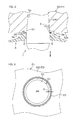
- FIG. 3 is a diagram of the knuckle arm 51 as seen in an arrow direction III in FIG. 2 .
- a grease retaining groove 55 (a hatched portion in FIG. 3 ) serving as a grease retaining portion for retaining grease G is provided in a portion of the lower surface 52b opposed to the second sliding contact surface 33.
- the grease retaining groove 55 surrounds an opening 56 of the knuckle hole 53, and has an annular shape coaxial with the peripheral wall 54 of the round opening 56 of the knuckle hole 53.
- the grease retaining groove 55 has an inverted semicircular cross section taken perpendicularly to an extending direction thereof as shown in FIG. 2 .
- the inner peripheral edge of the grease retaining grove 55 is spaced a predetermined distance S from the peripheral wall 54 of the opening 56.
- the grease retaining groove 55 is formed, for example, by grinding or cutting the portion of the lower surface 52b around the opening 56 of the knuckle hole 53.
- FIG. 3 illustrates a state in which the grease G is not retained in the grease retaining groove 55.
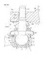
- FIGS. 4A and 4B are sectional views for explaining an exemplary mounting method for mounting the ball joint 1 on the knuckle arm 51.
- the mounting method shown in FIGS. 4A and 4B includes a grease putting step, a shaft inserting step and a shaft fixing step, which are performed in this order. That is, the grease G is put (retained) in the grease retaining groove 55 before the shaft 12 of the ball stud 4 is inserted into the knuckle hole 53.
- the grease G retained in the grease retaining groove 55 may be of the same type (having the same viscosity) as the grease filled between the round head 11 and the resin sheet 3.
- the grease G is ejected from a grease ejecting nozzle 57 toward the grease retaining groove 55 to be thereby retained in the grease retaining groove 55.
- a workpiece the bracket 52 of the knuckle arm 51
- the nozzle 57 is rotated about the knuckle hole 53.
- the grease G can be retained in the entire grease retaining groove 55.
- the grease retaining groove 55 is preferably fully filled with the grease G. That is, the grease G is preferably retained in the grease retaining groove 55 in an amount such that the grease G is just about to flow out of the grease retaining groove 55.
- the grease G is semisolid at ordinary temperatures, and has substantially no fluidity. Therefore, the grease G supplied into the grease retaining groove 55 hardly flows out of the grease retaining groove 55. That is, the grease G is not present on a portion of the lower surface 52b adjacent to the opening 56 of the knuckle hole 53.
- the shaft inserting step is performed. That is, the shaft 12 of the ball stud 4 is inserted into the knuckle hole 53.
- the annular projection 34 is provided along the outer periphery of the second sliding contact surface 33 as projecting away from the housing 2 in a state before the shaft inserting step (i.e., before the mounting of the ball stud 4).
- the annular projection 34 has a triangular cross section taken perpendicularly to the circumference thereof, and the outward projection degree of the annular projection 34 increases in an upward direction.
- a portion of the second sliding contact surface 33 excluding the outer periphery is generally flat.
- the grease retaining groove 55 is opposed to the second sliding contact surface 33.
- the shaft 12 of the ball stud 4 is inserted into the knuckle hole 53 to be squeezed into the inner side of the knuckle hole 53.
- the grease G is not present on the portion of the lower surface 52b adjacent to the opening 56 of the knuckle hole 53. Therefore, the grease G is not drawn into the knuckle hole 53 by the insertion of the shaft 12 in the knuckle hole 53.
- the upper end portion 5a is brought into contact with the lower surface 52b by the insertion of the shaft 12. After the contact between the upper end portion 5a and the lower surface 52b, the grease G is spread between the upper end portion 5a and the lower surface 52b to reach the outer periphery of the shaft 12 (as indicated by a bold line in FIG. 2 ).
- the shaft fixing step is performed. More specifically, the male thread portion 31 projects rearward (upward in FIG. 4B ) from the bracket 52 with the shaft 12 of the ball stud 4 sufficiently squeezed in the knuckle hole 53. A nut 30 (see FIG. 1 ) is threadingly engaged with the male thread portion 31 to be tightened, whereby the ball stud 4 is fixed to the knuckle arm 51. Thus, the ball joint 1 is fixed to the knuckle arm 51 to be thereby mounted on the knuckle arm 51.
- the upper end portion 5a is slid on the outer periphery of the shaft 12 of the ball stud 4 as the ball stud 4 is pivoted and rotated.
- the grease G reaching the outer periphery of the shaft 12 is distributed (infiltrates) between the first sliding contact surface 32 of the upper end portion 5a and the outer periphery of the shaft 12.
- the ball stud 4 is not relatively displaced with respect to the knuckle arm 51, so that the grease G reaching the outer periphery of the shaft 12 is hardly supplied between the peripheral wall 54 of the knuckle hole 53 and the outer periphery of the shaft 12. This makes it possible to distribute the grease G between the outer periphery of the shaft 12 and the first sliding contact surface 32 of the upper end portion 5a, while preventing the grease G from being supplied into the knuckle hole 53.
- the grease retaining groove is a grease retaining groove 55A shown in FIG. 5 .
- the lower surface 52b includes a first annular portion 58 provided around the opening 56 of the knuckle hole 53 and having an annular shape, and a second annular portion 59 surrounding the first annular portion 58 and having an annular shape.
- the first annular portion 58 is indented from the second annular portion 59.
- the grease retaining groove 55A is disposed along a boundary between the first and second annular portions 58 and 59.
- the grease retaining groove 55A has substantially the same structure as the grease retaining groove 55.
- a level difference between the bottom of the grease retaining groove 55A and the first annular portion 58 is different from a level difference between the bottom of the grease retaining groove 55A and the second annular portion 59. Therefore, the grease G retained in the grease retaining groove 55A is guided toward the second annular portion 59 rather than toward the first annular portion 58. Therefore, the grease G is reliably prevented from being supplied into the knuckle hole 53.
- the grease retaining groove 55A is a grease retaining groove 55B shown in FIG. 6 .
- the grease retaining groove 55B is a V-shaped annular groove (having a V-shaped cross section taken perpendicularly to a groove extending direction).
- the embodiment described above is directed to the case in which the grease retaining groove 55, 55A or 55B is provided as the grease retaining portion.
- a plurality of grease retaining recesses 60 may be provided as the grease retaining portion.
- the grease retaining recesses 60 are equidistantly arranged along a circle coaxial with the peripheral wall 54 of the round opening 56 of the knuckle hole 53.
- the grease retaining recesses 60 each have, for example, a generally semispherical shape.
- FIG. 8 is a diagram showing the major structures of a ball joint 1 and a knuckle arm 51 of a ball joint mount structure according to further another embodiment of the present invention.
- FIG. 8 illustrates a state after the ball joint 1 is mounted on the knuckle arm 51.
- the mount structure according to this embodiment is such that a ball joint 1 provided in a connection portion between a knuckle arm 51 of a suspension system and a steering system is mounted on the knuckle arm 51 (mount member).
- the ball joint 1 supports the knuckle arm 51 in a vertically movable and turnable manner.
- the knuckle arm 51 includes a knuckle body (not shown) such as of aluminum, and a bracket 52 of aluminum connected to a lower portion of the knuckle body.
- the bracket 52 has a knuckle hole (mount hole) 53 provided at a mount position in a planar portion thereof (mount portion, which is one end portion (right end portion in FIG. 8 ) in this embodiment) as extending from an upper surface 52a to a lower surface 52b thereof.
- the knuckle hole 53 opens in the lower surface (mount surface) 52b.
- the knuckle hole 53 is an insertion hole though which a ball stud shaft 12 is inserted, and has a generally cylindrical peripheral wall (interior wall) 54.
- the peripheral wall 54 of the knuckle hole 53 has a taper shape which has a diameter increasing toward a lower end thereof.
- the ball joint 1 includes a tubular housing 2, a resin sheet 3 and a ball stud 4 retained in the housing 2, and a tubular boot 5 attached to the housing 2.
- the housing 2 includes a tubular member 6 in which the resin sheet 3 is disposed, and a plug plate 7 fixed to a lower end of the tubular member 6 to close the lower end of the tubular member 6.
- the tubular member 6 has an upper end portion which is defined as an open end portion 6a.
- the resin sheet 3 has a cup shape, and includes a tubular peripheral wall portion 8 and a bottom portion 9 provided at a lower end of the peripheral wall portion 8.
- the resin sheet 3 is disposed with its peripheral wall portion 8 fitted on an inner peripheral surface of the tubular member 6 and with its bottom portion 9 opposed to the plug plate 7.
- the resin sheet 3 is held between an annular flange 10 provided at the open end portion 6a and the plug plate 7.
- the flange 10 has an inner diameter that is smaller than the outer diameter of a part (a round head 11 to be described later) of the ball stud 4. Therefore, the open end portion 6a prevents the part of the ball stud 4 and the resin sheet 3 from being withdrawn from the tubular member 6.
- the ball stud 4 is a metal member which integrally includes a round head 11 having a spherical outer peripheral surface and a shaft 12 projecting upward from the round head 11.
- the round head 11 is disposed with its center aligning on a center axis of the shaft 12.
- the shaft 12 has a male thread portion 31 provided at a distal end thereof.
- the shaft 12 includes a generally cylindrical trunk portion 12A provided between the male thread portion 31 and the round head 11 thereof.
- the trunk portion 12A With the ball joint 1 mounted on the knuckle arm 51, the trunk portion 12A is accommodated in the knuckle hole 53. Therefore, the trunk portion 12A has an outer periphery configured and dimensioned so as to be conformal to the peripheral wall 54 of the knuckle hole 53.
- the outer periphery of the trunk portion 12A has a taper shape which has a diameter increasing toward a lower end thereof.
- the resin sheet 3 has an inner peripheral surface conformal to the outer peripheral surface of the round head 11. Grease is filled between the resin sheet 3 and the round head 11.
- the round head 11 is slidable with respect to the resin sheet 3.
- the ball stud 4 is pivotal about the round head 11 with respect to the housing 2.
- the ball stud 4 is rotatable about the center axis of the shaft 12.
- the boot 5 is configured in a tubular shape such that an upper end portion (one end, lip) 5a thereof has a smaller diameter than a lower end portion (the other end) 5b thereof, and an intermediate portion thereof is bulged outward from the lower end portion 5b.
- the boot 5 is made of a resilient material (e.g., a chloroprene rubber (CR), an acrylonitrile butadiene rubber (NBR), a natural rubber or the like).
- the upper end portion 5a of the boot 5 is fitted around an intermediate portion of the shaft 12 in resilient contact with the outer periphery of the trunk 12A (the outer periphery of the shaft 12). In a state shown in FIG. 8 , the upper end portion 5a of the boot 5 also contacts the lower surface 52b.
- the lower end portion 5b of the boot 5 is fitted around the open end portion 6a of the tubular member 6.
- the lower end portion 5b of the boot 5 is fixed to the tubular member 6 by a fixture ring 13 attached to the lower end portion 5b. More specifically, the housing 2 has an annular groove 14 circumferentially provided in an outer periphery of the open end portion 6a thereof for attachment of the boot. An opening defined within the open end portion 6a is covered with the boot 5, whereby foreign matter such as water and dust is prevented from intruding into the ball joint 1.
- the lower end portion 5b of the boot 5 is inserted in the annular groove 14.
- the lower end portion 5b includes a cylindrical portion 21, and an annular turn-back portion 22 turned back from a distal edge of the cylindrical portion 21 as extending outward.
- the cylindrical portion 21 has an axial length that is substantially equal to the width of the annular groove 14, and is disposed in the annular groove 14 with its inner peripheral surface in intimate contact with a bottom of the annular groove 14.
- the fixture ring 13 is a resilient member, for example, having a C-shape as seen in plan. The fixture ring 13 is fitted around the cylindrical portion 21 in the annular groove 14 to clamp the cylindrical portion 21 from the outer side to fix the cylindrical portion 21 to the tubular member 6.
- the upper end portion 5a of the boot 5 is generally cylindrical.
- the upper end portion 5a has a generally cylindrical first sliding contact surface 32 kept in sliding contact with the outer periphery of the trunk portion 12A, and an annular second sliding contact surface 33 kept in sliding contact with the lower surface 52b in the state shown in FIG. 8 .
- the first sliding contact surface 32 is entirely kept in sliding contact with the outer periphery of the trunk portion 12A.
- the second sliding contact surface 33 defines an upper end face of the upper end portion 5a.
- the second sliding contact surface 33 is continuous to the first sliding contact surface 32, and generally perpendicular to the first sliding contact surface 32.
- the second sliding contact surface 33 is pressed against the lower surface 52b to be deformed.
- the second sliding contact surface 33 includes an annular projection 34 provided along an outer periphery thereof as projecting away from the housing 2. In the state shown in FIG. 8 , the annular projection 34 kept in contact with the lower surface 52b is pressed against the lower surface 52b to project outward (see FIG. 9 , though the annular projection 34 is not shown in FIG. 8 ).
- the first sliding contact surface 32 of the upper end portion 5a of the boot 5 is slid on the outer periphery of the trunk portion 12A, as the ball stud 4 is pivoted about the round head 11. Further, the first sliding contact surface 32 of the upper end portion 5a of the boot 5 is slid on the outer periphery of the trunk portion 12A, as the ball stud 4 is rotated about the center axis of the shaft 12.
- An annular step (step) 80 is provided in the peripheral wall 54 of the open end portion 56A (opening 56) of the knuckle hole 53 to be continuous to the lower surface 52b.
- An annular seal member 70 is accommodated in the annular step 80 in contact with the outer periphery of the trunk portion 12A for sealing a gap between the outer periphery of the trunk portion 12A and the peripheral wall 54.
- the seal member 70 is accommodated in the annular step 80 in intimate contact with an outer peripheral wall 81 and an annular wall 82 of the annular step 80.
- the seal member 70 is an O-ring.
- the seal member 70 may have, for example, a round sectional shape, as shown in FIGS. 8 and 9 , or an oval sectional shape taken perpendicularly to the circumference thereof.
- Exemplary materials for the seal member 70 include a nitrile rubber and a silicone rubber.
- the annular step 80 is formed, for example, by grinding or cutting a portion of the peripheral wall 54 of the opening 56 of the knuckle hole 53 (the lowermost portion of the peripheral wall 54).
- FIG. 9 is a sectional view for explaining an exemplary mounting method for mounting the ball joint 1 on the knuckle arm 51.
- the mounting method for mounting the ball joint 1 on the knuckle arm 51 includes a shaft inserting step and a shaft fixing step, which are performed in this order.
- an operator Before inserting the shaft 12 of the ball stud 4 into the knuckle hole 53, an operator applies the grease G onto at least one of the first sliding contact surface 32 and the outer periphery of the trunk portion 12A (more specifically, a portion of the outer periphery of the trunk portion 12A opposed to the first sliding contact surface 32).
- the grease G is present between the first sliding contact surface 32 and the outer periphery of the trunk portion 12A (the portion of the outer periphery of the trunk portion 12A opposed to the first sliding contact surface 32), lubrication between the outer periphery of the trunk portion 12A and the upper end portion 5a is enhanced.
- the application of the grease G onto the second sliding contact surface 33 may be simultaneous with the application of the grease G onto one of the first sliding contact surface 32 and the outer periphery of the trunk portion 12A.
- the portion of the outer periphery of the trunk portion 12A of the shaft 12 retaining the applied grease G is indicated by characters "x".
- the grease G applied onto the sliding contact surfaces 32, 33 and the outer periphery of the shaft 12 may be of the same type (having the same viscosity) as the grease filled between the round head 11 and the resin sheet 3.
- the shaft inserting step In the shaft inserting step, the shaft 12 of the ball stud 4 is inserted into the knuckle hole 53.
- the annular projection 34 is provided along the outer periphery of the second sliding contact surface 33 as projecting away from the housing 2.
- the annular projection 34 has a triangular cross section taken perpendicularly to the circumference thereof, and the outward projection degree of the annular projection 34 increases in an upward direction.
- a portion of the second sliding contact surface 33 excluding the outer periphery is generally flat.
- the inner periphery of the seal member 70 slightly projects radially inward of the peripheral wall 54.
- the shaft 12 of the ball stud 4 is inserted into the knuckle hole 53 to be squeezed into the inner side of the knuckle hole 53.
- the seal member 70 is brought into contact with the outer periphery of the trunk 12A of the shaft 12 to scrape the grease G adhering to the outer periphery of the trunk 12A. Therefore, the grease G adhering to the outer periphery of the trunk 12A is hardly drawn into the knuckle hole 53.
- the shaft fixing step is performed. More specifically, the male thread portion 31 projects rearward (upward in FIG. 9 ) from the bracket 52 with the shaft 12 of the ball stud 4 sufficiently squeezed in the knuckle hole 53. A nut 30 (see FIG. 8 ) is threadingly engaged with the male thread portion 31 to be tightened, whereby the ball stud 4 is fixed to the knuckle arm 51. Thus, the ball joint 1 is fixed to the knuckle arm 51 to be thereby mounted on the knuckle arm 51.
- the seal member 70 is kept in contact with the outer periphery of the trunk 12A to seal the gap between the outer periphery of the trunk 12A and the peripheral wall 54 of the opening 56 of the knuckle hole 53. This prevents the grease G from intruding into the knuckle hole 53. Thus, the grease G is prevented from being supplied into the knuckle hole 53, even if the grease G is applied onto at least one of the first sliding contact surface 32 and the outer periphery of the trunk 12A before the mounting of the ball joint 1.
- FIG. 10 is a major sectional view of a knuckle arm of a ball joint mount structure according to still another embodiment of the present invention.
- components corresponding to those shown in FIGS. 8 and 9 will be designated by the same reference characters as in FIGS. 8 and 9 , and duplicate description will be omitted.
- the mount structure shown in FIG. 10 differs from the mount structure shown in FIGS. 8 and 9 in that an annular groove 80A is provided in the peripheral wall 54 of the opening 56 of the knuckle hole 53 and a seal member 70 is accommodated in the annular groove 80A. More specifically, the annular groove 80A has a rectangular cross section taken perpendicularly to the circumference thereof.
- the annular groove 80A is provided in the peripheral wall 54 of the knuckle hole 53 as spaced a predetermined distance S inward from an open end portion 56A of the knuckle hole 53.
- the seal member 70 is accommodated in the annular groove 80A in intimate contact with a bottom wall 86 and opposite side walls 87, 88 of the annular groove 80A. In a state shown in FIG. 10 , the inner periphery of the seal member 70 slightly projects radially inward from a line extending between an inner edge of the side wall 87 and an inner edge of the side wall 88.
- the embodiments described above are directed to the case in which the ball joint 1 is mounted on the knuckle arm 51 of the suspension system.
- the inventive mount structure is applicable to a mount structure including a ball joint 1 mounted on a knuckle arm of a steering system.
Landscapes
- Engineering & Computer Science (AREA)
- General Engineering & Computer Science (AREA)
- Mechanical Engineering (AREA)
- Chemical & Material Sciences (AREA)
- Combustion & Propulsion (AREA)
- Transportation (AREA)
- Pivots And Pivotal Connections (AREA)
Abstract
Description
- The present invention relates to a ball joint mount structure and a ball joint mounting method for mounting a ball joint on a mount member.
- A ball joint (so-called outer ball joint) is provided, for example, in a connection portion between a knuckle arm of a suspension system and a steering system for supporting the knuckle arm in a vertically movable and turnable manner. The ball joint includes a metal ball stud having a round head provided at a proximal end of a shaft, a bottomed cylindrical housing accommodating the round head therein with the shaft projecting from an opening thereof, a synthetic resin sheet provided between the housing and the round head, and a tubular rubber boot attached to the housing (see, for example,
JP-2008-128351-A - The boot covers the opening of the housing, and is fitted around an intermediate portion of the shaft at one of opposite ends thereof and fitted around an open end portion of the housing (formed with the opening) at the other end thereof. The one end of the boot has a lip which is kept in resilient contact with an outer periphery of the shaft of the ball stud.
- The ball joint is mounted in a planar mount portion of the knuckle arm. The mount portion of the knuckle arm to be mounted with the ball joint has a knuckle hole extending therethrough. The shaft of the ball stud is inserted in the knuckle hole, and then a male-thread distal end portion of the shaft projecting rearward of the knuckle arm is brought into threading engagement with a nut, which is in turn tightened. Thus, the ball stud is fixed to the knuckle arm, whereby the ball joint is mounted on the knuckle arm.
- In recent years, there has been a demand for further enhancement of the sealability of the boot.
- The inventors of the present invention contemplate that the sealability of the boot is enhanced by increasing the tightness of the boot as compared with the prior art. If the boot is highly tight, however, the pressure of the contact between the outer periphery of the shaft and the lip is increased, resulting in abnormal abrasion of the lip.
- A conceivable approach to enhancement of lubrication between the outer periphery of the shaft and the lip is to provide grease or the like between a sliding contact surface of the lip and the outer periphery of the shaft. In this case, however, grease adhering to the outer periphery of the shaft is liable to be drawn into the mount hole when the shaft is inserted into the mount hole in the mounting of the ball joint. That is, the grease is liable to be supplied not only between the outer periphery of the shaft and the sliding contact surface of the lip but also into the mount hole. When the grease is supplied into the mount hole, an engagement force between the nut and the shaft is liable to be changed, thereby adversely influencing the ball joint in various ways.
- It is an object of the present invention to provide a ball joint mount structure and a ball joint mounting method, which can distribute the grease between the outer periphery of the shaft and the sliding contact surface of the lip while preventing the grease from being supplied into the mount hole.
- It is another object of the present invention to provide a ball joint mount structure which can prevent the grease from being supplied into the mount hole even if the grease is applied onto at least one of the lip and the outer periphery of the shaft before the mounting of the ball joint.
- According to an inventive aspect of claim 1, there is provided a ball joint mount structure, which includes: a ball joint (1) including a ball stud (4) having a shaft (12) and a round head (11) provided at one end of the shaft, a housing (2) having an opening and accommodating the round head therein with the shaft projecting from the opening, and a tubular boot (5) fitted around an intermediate portion of the shaft at one (5a) of opposite ends thereof and fitted around the housing at the other end (5b) thereof; and a mount member (51) having a mount surface (52b) and a mount hole (53) opening in the mount surface; the ball joint being mounted on the mount member with the shaft inserted in the mount hole and engaged with the mount member; the boot including an annular lip (5a) provided at the one end thereof with an inner peripheral surface (32) of the lip in contact with an outer periphery of the shaft and with one end face (33) of the lip in contact with the mount surface; the mount member including a grease retaining portion (55; 55A; 55B; 60) provided in a portion of the mount surface thereof spaced a distance (S) from a peripheral edge of the mount hole as opposed to the one end face of the lip for retaining grease (G).
- Parenthesized alphanumeric characters respectively denote corresponding components to be described in the following embodiments, but are not intended to limit the scope of the invention to these embodiments. This definition is applied to the following description in this section.
- With this arrangement, the grease retaining portion for retaining the grease is provided in the portion of the mount surface spaced the distance from the peripheral edge of the mount hole as opposed to the one end face of the lip. After the grease is retained in the grease retaining portion, the shaft is inserted in the mount hole.
- At this time, no grease is present on a portion of the mount surface adjacent to an opening of the mount hole. Therefore, the grease is hardly drawn into the mount hole during the insertion of the shaft into the mount hole. When the one end face of the lip is brought into contact with the mount surface by the insertion of the shaft, the grease is spread between the lip and the mount surface to reach the outer periphery of the shaft.
- After the mounting of the ball joint, the lip is slid around the shaft of the ball stud as the ball stud is pivoted and rotated. Thus, the grease reaching the outer periphery of the shaft is distributed (infiltrates) between the inner peripheral surface of the lip and the outer periphery of the shaft.
- On the other hand, the ball stud is not relatively displaced with respect to the mount member. Therefore, the grease reaching the outer periphery of the shaft hardly moves toward an inner side of an interior wall of the mount hole. This makes it possible to distribute the grease between the outer periphery of the shaft and the inner peripheral surface of the lip while preventing the grease from being supplied into the mount hole.
- According to an inventive aspect of
claim 2, the grease retaining portion may include an annular groove (55; 55A; 55B) surrounding the mount hole. - According to an inventive aspect of
claim 3, the grease retaining portion may include a plurality of recesses (60) provided around the mount hole. - According to an inventive aspect of
claim 4, there is provided a ball joint mounting method for mounting a ball joint (1) on a mount member (51), the ball joint (1) including a ball stud (4) having a shaft (12) and a round head (11) provided at one end of the shaft, a housing (2) having an opening and accommodating the round head therein with the shaft projecting from the opening, and a tubular boot (5) fitted around an intermediate portion of the shaft at one (5a) of opposite ends thereof and fitted around the housing at the other end (5b) thereof to cover the opening, the boot including a lip (5a) provided at the one end thereof in resilient contact with an outer periphery of the shaft, the mount member (51) having a mount surface (52b) and a mount hole (53) opening in the mount surface, the method comprising: a grease putting step of putting grease (G) in a grease retaining portion (55; 55A; 55B; 60) provided in a portion of the mount surface spaced a distance (S) from a peripheral edge of the mount hole; a shaft inserting step of inserting the shaft into the mount hole to bring the lip into contact with the mount surface after the grease putting step; and a shaft fixing step of fixing the shaft inserted into the mount hole to the mount member after the shaft inserting step. - The inventive method provides the same effects as described with respect to claim 1.
- According to an inventive aspect of
claim 5, there is provided a ball joint mount structure, which includes: a ball joint (1) including a ball stud (4) having a shaft (12) and a round head (11) provided at one end of the shaft, a housing (2) having an opening and accommodating the round head therein with the shaft projecting from the opening, and a tubular boot (5) fitted around an intermediate portion of the shaft at one (5a) of opposite ends thereof and fitted around the housing at the other end (5b) thereof; and a mount member (51) having a mount surface (52b) and a mount hole (53) opening in the mount surface; the ball joint being mounted on the mount member with the shaft inserted in the mount hole and engaged with the mount member; the boot including an annular lip (5a) provided at the one end thereof with an inner peripheral surface (32) of the lip in contact with an outer periphery of the shaft and with one end face (33) of the lip in contact with the mount surface; wherein grease (G) is supplied between the inner peripheral surface of the lip and the outer periphery of the shaft, and an annular seal member (70) is provided in an interior wall (54) of an opening (56) of the mount hole in contact with the outer periphery of the shaft for suppressing intrusion of the grease. - With this arrangement, the annular seal member is provided on the interior wall of the opening of the mount hole. When the shaft is inserted into the mount hole, the annular seal member is brought into contact with the outer periphery of the shaft to scrape grease adhering to the outer periphery of the shaft from the outer periphery of the shaft. Therefore, the grease adhering to the outer periphery of the shaft is hardly drawn into the mount hole. Further, the annular seal member is kept in contact with the outer periphery of the shaft to prevent the grease from intruding into the mount hole after the insertion of the shaft in the mount hole. Thus, the intrusion of the grease in the mount hole can be prevented even if the grease is applied onto at least one of the lip and the outer periphery of the shaft before the mounting.
- According to an inventive aspect of
claim 6, a step (80) may be provided in the interior wall of the opening of the mount hole to accommodate the seal member. - According to an inventive aspect of
claim 7, an annular groove (80A) is provided in the interior wall of the opening of the mount hole to accommodate the seal member. - According to an inventive aspect of
claim 8, the grease may be supplied between the one end face of the lip and the mount surface. -
-
FIG. 1 is a partial sectional view illustrating major portions of a ball joint and a knuckle arm of a ball joint mount structure according to one embodiment of the present invention. -
FIG. 2 is an enlarged partial sectional view of the ball joint and the knuckle arm shown inFIG. 1 . -
FIG. 3 is a diagram of the knuckle arm as seen in an arrow direction III inFIG. 2 . -
FIG. 4A is a sectional view for explaining an exemplary method for mounting the ball joint on the knuckle arm. -
FIG. 4B is another sectional view for explaining the exemplary method for mounting the ball joint on the knuckle arm. -
FIG. 5 is a major sectional view of a knuckle arm of a first modification of the ball joint mount structure. -
FIG. 6 is a major sectional view of a knuckle arm of a second modification of the ball joint mount structure. -
FIG. 7 is a major sectional view of a knuckle arm of a ball joint mount structure according to another embodiment of the present invention. -
FIG. 8 is a partial sectional view illustrating major portions of a ball joint and a knuckle arm of a ball joint mount structure according to further another embodiment of the present invention. -
FIG. 9 is a sectional view for explaining how to mount the ball joint on the knuckle arm. -
FIG. 10 is a major sectional view of a knuckle arm of a ball joint mount structure according to still another embodiment of the present invention. - Embodiments of the present invention will hereinafter be described in detail with reference to the attached drawings.
-
FIG. 1 is a diagram showing the major structures of a ball joint 1 and aknuckle arm 51 of a ball joint mount structure according to one embodiment of the present invention.FIG. 1 illustrates a state after the ball joint 1 is mounted on theknuckle arm 51. The mount structure according to this embodiment is such that a ball joint 1 provided in a connection portion between aknuckle arm 51 of a suspension system and a steering system is mounted on the knuckle arm 51 (mount member). The ball joint 1 supports theknuckle arm 51 in a vertically movable and turnable manner. - The
knuckle arm 51 includes a knuckle body (not shown) such as of aluminum, and abracket 52 of aluminum connected to a lower portion of the knuckle body. Thebracket 52 has a knuckle hole (mount hole) 53 provided at a mount position in a planar portion thereof (mount portion, which is one end portion (right end portion inFIG. 1 ) in this embodiment) as extending from anupper surface 52a to alower surface 52b thereof. In other words, theknuckle hole 53 opens in the lower surface (mount surface) 52b. Theknuckle hole 53 is an insertion hole though which aball stud shaft 12 is inserted, and has a generally cylindrical peripheral wall (interior wall) 54. Theperipheral wall 54 has a taper shape which has a diameter increasing toward a lower end thereof. - The ball joint 1 includes a
tubular housing 2, aresin sheet 3 and aball stud 4 retained in thehousing 2, and atubular boot 5 attached to thehousing 2. Thehousing 2 includes atubular member 6 in which theresin sheet 3 is disposed, and aplug plate 7 fixed to a lower end of thetubular member 6 to close the lower end of thetubular member 6. Thetubular member 6 has an upper end portion which is defined as anopen end portion 6a. - The
resin sheet 3 has a cup shape, and includes a tubularperipheral wall portion 8 and a bottom portion 9 provided at a lower end of theperipheral wall portion 8. Theresin sheet 3 is disposed with itsperipheral wall portion 8 fitted on an inner peripheral surface of thetubular member 6 and with its bottom portion 9 opposed to theplug plate 7. Theresin sheet 3 is held between anannular flange 10 provided at theopen end portion 6a and theplug plate 7. Theflange 10 has an inner diameter that is smaller than the outer diameter of a part (around head 11 to be described later) of theball stud 4. Therefore, theopen end portion 6a prevents the part of theball stud 4 and theresin sheet 3 from being withdrawn from thetubular member 6. - The
ball stud 4 is a metal member which integrally includes around head 11 having a spherical outer peripheral surface and ashaft 12 projecting upward from theround head 11. Theround head 11 is disposed with its center aligning on a center axis of theshaft 12. Theshaft 12 has amale thread portion 31 provided at a distal end thereof. Theround head 11 is covered with theresin sheet 3 in thetubular member 6, and theshaft 12 projects from theopen end portion 6a of thetubular member 6. Theround head 11 except for a portion thereof adjacent to theshaft 12 is mostly covered with theresin sheet 3. Theround head 11 is retained in thehousing 2 with theresin sheet 3 interposed between theround head 11 and thehousing 2. - The
resin sheet 3 has an inner peripheral surface conformal to the outer peripheral surface of theround head 11. Grease is filled between theresin sheet 3 and theround head 11. Theround head 11 is slidable with respect to theresin sheet 3. Theball stud 4 is pivotal about theround head 11 with respect to thehousing 2. Theball stud 4 is rotatable about the center axis of theshaft 12. - The
boot 5 is configured in a tubular shape such that an upper end portion (one end, lip) 5a thereof has a smaller diameter than a lower end portion (the other end) 5b thereof, and an intermediate portion thereof is bulged outward from thelower end portion 5b. Theboot 5 is made of a resilient material (e.g., a chloroprene rubber (CR), an acrylonitrile butadiene rubber (NBR), a natural rubber or the like). Theupper end portion 5a of theboot 5 is fitted around an intermediate portion of theshaft 12 in resilient contact with an outer periphery of theshaft 12. In a state shown inFIG. 1 , theupper end portion 5a of theboot 5 also contacts thelower surface 52b. Thelower end portion 5b of theboot 5 is fitted around theopen end portion 6a of thetubular member 6. - The
lower end portion 5b of theboot 5 is fixed to thetubular member 6 by afixture ring 13 attached to thelower end portion 5b. More specifically, thehousing 2 has anannular groove 14 circumferentially provided in an outer periphery of theopen end portion 6a thereof for attachment of the boot. An opening defined within theopen end portion 6a is covered with theboot 5, whereby foreign matter such as water and dust is prevented from intruding into the ball joint 1. - The
lower end portion 5b of theboot 5 is inserted in theannular groove 14. Thelower end portion 5b includes acylindrical portion 21, and an annular turn-back portion 22 turned back from a distal edge of thecylindrical portion 21 as extending outward. Thecylindrical portion 21 has an axial length that is substantially equal to the width of theannular groove 14, and is disposed in theannular groove 14 with its inner peripheral surface in intimate contact with a bottom of theannular groove 14. Thefixture ring 13 is a resilient member, for example, having a C-shape as seen in plan. Thefixture ring 13 is fitted around thecylindrical portion 21 in theannular groove 14 to clamp thecylindrical portion 21 from the outer side to fix thecylindrical portion 21 to thetubular member 6. -
FIG. 2 is an enlarged partial sectional view of the ball joint 1 and theknuckle arm 51. Reference will hereinafter be made toFIGS. 1 and2 . - The
upper end portion 5a of theboot 5 is generally cylindrical. Theupper end portion 5a has a generally cylindrical first sliding contact surface (inner peripheral surface) 32 kept in sliding contact with the outer periphery of theshaft 12, and an annular second sliding contact surface (one end face) 33 kept in sliding contact with thelower surface 52b in the state shown inFIG. 1 . The first slidingcontact surface 32 is entirely kept in sliding contact with the outer periphery of theshaft 12. - The second sliding
contact surface 33 defines an upper end face of theupper end portion 5a. The second slidingcontact surface 33 is continuous to the first slidingcontact surface 32, and generally perpendicular to the first slidingcontact surface 32. With the ball joint 1 mounted on theknuckle arm 51 as shown inFIG. 1 , the second slidingcontact surface 33 is pressed against thelower surface 52b to be deformed. More specifically, as shown inFIG. 4B to be described later, the second slidingcontact surface 33 includes anannular projection 34 provided along an outer periphery thereof as projecting away from thehousing 2. In the state shown inFIG. 1 , theannular projection 34 kept in contact with thelower surface 52b is pressed against thelower surface 52b to project outward (seeFIG. 2 , though theannular projection 34 is not shown inFIG. 1 ). - The first sliding
contact surface 32 of theupper end portion 5a of theboot 5 is slid on the outer periphery of theshaft 12, as theball stud 4 is pivoted about theround head 11. Further, the first slidingcontact surface 32 of theupper end portion 5a of theboot 5 is slid on the outer periphery of theshaft 12, as theball stud 4 is rotated about the center axis of theshaft 12. -
FIG. 3 is a diagram of theknuckle arm 51 as seen in an arrow direction III inFIG. 2 . As shown inFIGS. 1 to 3 , a grease retaining groove 55 (a hatched portion inFIG. 3 ) serving as a grease retaining portion for retaining grease G is provided in a portion of thelower surface 52b opposed to the second slidingcontact surface 33. Thegrease retaining groove 55 surrounds anopening 56 of theknuckle hole 53, and has an annular shape coaxial with theperipheral wall 54 of theround opening 56 of theknuckle hole 53. Thegrease retaining groove 55 has an inverted semicircular cross section taken perpendicularly to an extending direction thereof as shown inFIG. 2 . The inner peripheral edge of thegrease retaining grove 55 is spaced a predetermined distance S from theperipheral wall 54 of theopening 56. Thegrease retaining groove 55 is formed, for example, by grinding or cutting the portion of thelower surface 52b around theopening 56 of theknuckle hole 53. - In the state shown in
FIG. 1 , the second slidingcontact surface 33 is kept in contact with thelower surface 52b, so that the grease G retained in thegrease retaining groove 55 is supplied to the second slidingsurface 33.FIG. 3 illustrates a state in which the grease G is not retained in thegrease retaining groove 55. -
FIGS. 4A and4B are sectional views for explaining an exemplary mounting method for mounting the ball joint 1 on theknuckle arm 51. - The mounting method shown in
FIGS. 4A and4B includes a grease putting step, a shaft inserting step and a shaft fixing step, which are performed in this order. That is, the grease G is put (retained) in thegrease retaining groove 55 before theshaft 12 of theball stud 4 is inserted into theknuckle hole 53. The grease G retained in thegrease retaining groove 55 may be of the same type (having the same viscosity) as the grease filled between theround head 11 and theresin sheet 3. - In the grease putting step, as shown in
FIG. 4A , the grease G is ejected from agrease ejecting nozzle 57 toward thegrease retaining groove 55 to be thereby retained in thegrease retaining groove 55. In the grease putting step, a workpiece (thebracket 52 of the knuckle arm 51) or thenozzle 57 is rotated about theknuckle hole 53. Thus, the grease G can be retained in the entiregrease retaining groove 55. At this time, thegrease retaining groove 55 is preferably fully filled with the grease G. That is, the grease G is preferably retained in thegrease retaining groove 55 in an amount such that the grease G is just about to flow out of thegrease retaining groove 55. The grease G is semisolid at ordinary temperatures, and has substantially no fluidity. Therefore, the grease G supplied into thegrease retaining groove 55 hardly flows out of thegrease retaining groove 55. That is, the grease G is not present on a portion of thelower surface 52b adjacent to theopening 56 of theknuckle hole 53. - After the grease putting step, the shaft inserting step is performed. That is, the
shaft 12 of theball stud 4 is inserted into theknuckle hole 53. - As shown in
FIG. 4B , theannular projection 34 is provided along the outer periphery of the second slidingcontact surface 33 as projecting away from thehousing 2 in a state before the shaft inserting step (i.e., before the mounting of the ball stud 4). Theannular projection 34 has a triangular cross section taken perpendicularly to the circumference thereof, and the outward projection degree of theannular projection 34 increases in an upward direction. A portion of the second slidingcontact surface 33 excluding the outer periphery is generally flat. As shown inFIG. 4B , thegrease retaining groove 55 is opposed to the second slidingcontact surface 33. - The
shaft 12 of theball stud 4 is inserted into theknuckle hole 53 to be squeezed into the inner side of theknuckle hole 53. At this time, the grease G is not present on the portion of thelower surface 52b adjacent to theopening 56 of theknuckle hole 53. Therefore, the grease G is not drawn into theknuckle hole 53 by the insertion of theshaft 12 in theknuckle hole 53. Then, theupper end portion 5a is brought into contact with thelower surface 52b by the insertion of theshaft 12. After the contact between theupper end portion 5a and thelower surface 52b, the grease G is spread between theupper end portion 5a and thelower surface 52b to reach the outer periphery of the shaft 12 (as indicated by a bold line inFIG. 2 ). - After the
ball stud 4 is sufficiently squeezed into theknuckle hole 53, the shaft fixing step is performed. More specifically, themale thread portion 31 projects rearward (upward inFIG. 4B ) from thebracket 52 with theshaft 12 of theball stud 4 sufficiently squeezed in theknuckle hole 53. A nut 30 (seeFIG. 1 ) is threadingly engaged with themale thread portion 31 to be tightened, whereby theball stud 4 is fixed to theknuckle arm 51. Thus, the ball joint 1 is fixed to theknuckle arm 51 to be thereby mounted on theknuckle arm 51. - In use of the ball joint 1, the
upper end portion 5a is slid on the outer periphery of theshaft 12 of theball stud 4 as theball stud 4 is pivoted and rotated. Thus, the grease G reaching the outer periphery of theshaft 12 is distributed (infiltrates) between the first slidingcontact surface 32 of theupper end portion 5a and the outer periphery of theshaft 12. - On the other hand, the
ball stud 4 is not relatively displaced with respect to theknuckle arm 51, so that the grease G reaching the outer periphery of theshaft 12 is hardly supplied between theperipheral wall 54 of theknuckle hole 53 and the outer periphery of theshaft 12. This makes it possible to distribute the grease G between the outer periphery of theshaft 12 and the first slidingcontact surface 32 of theupper end portion 5a, while preventing the grease G from being supplied into theknuckle hole 53. - Another example of the grease retaining groove is a
grease retaining groove 55A shown inFIG. 5 . More specifically, thelower surface 52b includes a firstannular portion 58 provided around theopening 56 of theknuckle hole 53 and having an annular shape, and a secondannular portion 59 surrounding the firstannular portion 58 and having an annular shape. The firstannular portion 58 is indented from the secondannular portion 59. Thegrease retaining groove 55A is disposed along a boundary between the first and secondannular portions grease retaining groove 55A has substantially the same structure as thegrease retaining groove 55. In this example, a level difference between the bottom of thegrease retaining groove 55A and the firstannular portion 58 is different from a level difference between the bottom of thegrease retaining groove 55A and the secondannular portion 59. Therefore, the grease G retained in thegrease retaining groove 55A is guided toward the secondannular portion 59 rather than toward the firstannular portion 58. Therefore, the grease G is reliably prevented from being supplied into theknuckle hole 53. - Further another example of the
grease retaining groove 55A is agrease retaining groove 55B shown inFIG. 6 . Unlike thegrease retaining grooves grease retaining groove 55B is a V-shaped annular groove (having a V-shaped cross section taken perpendicularly to a groove extending direction). - The embodiment described above is directed to the case in which the
grease retaining groove FIG. 7 , a plurality of grease retaining recesses 60 (eight grease retaining recesses inFIG. 7 ) may be provided as the grease retaining portion. The grease retaining recesses 60 are equidistantly arranged along a circle coaxial with theperipheral wall 54 of theround opening 56 of theknuckle hole 53. The grease retaining recesses 60 each have, for example, a generally semispherical shape. -
FIG. 8 is a diagram showing the major structures of a ball joint 1 and aknuckle arm 51 of a ball joint mount structure according to further another embodiment of the present invention.FIG. 8 illustrates a state after the ball joint 1 is mounted on theknuckle arm 51. The mount structure according to this embodiment is such that a ball joint 1 provided in a connection portion between aknuckle arm 51 of a suspension system and a steering system is mounted on the knuckle arm 51 (mount member). The ball joint 1 supports theknuckle arm 51 in a vertically movable and turnable manner. - The
knuckle arm 51 includes a knuckle body (not shown) such as of aluminum, and abracket 52 of aluminum connected to a lower portion of the knuckle body. Thebracket 52 has a knuckle hole (mount hole) 53 provided at a mount position in a planar portion thereof (mount portion, which is one end portion (right end portion inFIG. 8 ) in this embodiment) as extending from anupper surface 52a to alower surface 52b thereof. In other words, theknuckle hole 53 opens in the lower surface (mount surface) 52b. Theknuckle hole 53 is an insertion hole though which aball stud shaft 12 is inserted, and has a generally cylindrical peripheral wall (interior wall) 54. Theperipheral wall 54 of theknuckle hole 53 has a taper shape which has a diameter increasing toward a lower end thereof. - The ball joint 1 includes a
tubular housing 2, aresin sheet 3 and aball stud 4 retained in thehousing 2, and atubular boot 5 attached to thehousing 2. Thehousing 2 includes atubular member 6 in which theresin sheet 3 is disposed, and aplug plate 7 fixed to a lower end of thetubular member 6 to close the lower end of thetubular member 6. Thetubular member 6 has an upper end portion which is defined as anopen end portion 6a. - The
resin sheet 3 has a cup shape, and includes a tubularperipheral wall portion 8 and a bottom portion 9 provided at a lower end of theperipheral wall portion 8. Theresin sheet 3 is disposed with itsperipheral wall portion 8 fitted on an inner peripheral surface of thetubular member 6 and with its bottom portion 9 opposed to theplug plate 7. Theresin sheet 3 is held between anannular flange 10 provided at theopen end portion 6a and theplug plate 7. Theflange 10 has an inner diameter that is smaller than the outer diameter of a part (around head 11 to be described later) of theball stud 4. Therefore, theopen end portion 6a prevents the part of theball stud 4 and theresin sheet 3 from being withdrawn from thetubular member 6. - The
ball stud 4 is a metal member which integrally includes around head 11 having a spherical outer peripheral surface and ashaft 12 projecting upward from theround head 11. Theround head 11 is disposed with its center aligning on a center axis of theshaft 12. Theshaft 12 has amale thread portion 31 provided at a distal end thereof. Theshaft 12 includes a generallycylindrical trunk portion 12A provided between themale thread portion 31 and theround head 11 thereof. With the ball joint 1 mounted on theknuckle arm 51, thetrunk portion 12A is accommodated in theknuckle hole 53. Therefore, thetrunk portion 12A has an outer periphery configured and dimensioned so as to be conformal to theperipheral wall 54 of theknuckle hole 53. In other words, the outer periphery of thetrunk portion 12A has a taper shape which has a diameter increasing toward a lower end thereof. - The
resin sheet 3 has an inner peripheral surface conformal to the outer peripheral surface of theround head 11. Grease is filled between theresin sheet 3 and theround head 11. Theround head 11 is slidable with respect to theresin sheet 3. Theball stud 4 is pivotal about theround head 11 with respect to thehousing 2. Theball stud 4 is rotatable about the center axis of theshaft 12. - The
boot 5 is configured in a tubular shape such that an upper end portion (one end, lip) 5a thereof has a smaller diameter than a lower end portion (the other end) 5b thereof, and an intermediate portion thereof is bulged outward from thelower end portion 5b. Theboot 5 is made of a resilient material (e.g., a chloroprene rubber (CR), an acrylonitrile butadiene rubber (NBR), a natural rubber or the like). Theupper end portion 5a of theboot 5 is fitted around an intermediate portion of theshaft 12 in resilient contact with the outer periphery of thetrunk 12A (the outer periphery of the shaft 12). In a state shown inFIG. 8 , theupper end portion 5a of theboot 5 also contacts thelower surface 52b. Thelower end portion 5b of theboot 5 is fitted around theopen end portion 6a of thetubular member 6. - The
lower end portion 5b of theboot 5 is fixed to thetubular member 6 by afixture ring 13 attached to thelower end portion 5b. More specifically, thehousing 2 has anannular groove 14 circumferentially provided in an outer periphery of theopen end portion 6a thereof for attachment of the boot. An opening defined within theopen end portion 6a is covered with theboot 5, whereby foreign matter such as water and dust is prevented from intruding into the ball joint 1. - The
lower end portion 5b of theboot 5 is inserted in theannular groove 14. Thelower end portion 5b includes acylindrical portion 21, and an annular turn-back portion 22 turned back from a distal edge of thecylindrical portion 21 as extending outward. Thecylindrical portion 21 has an axial length that is substantially equal to the width of theannular groove 14, and is disposed in theannular groove 14 with its inner peripheral surface in intimate contact with a bottom of theannular groove 14. Thefixture ring 13 is a resilient member, for example, having a C-shape as seen in plan. Thefixture ring 13 is fitted around thecylindrical portion 21 in theannular groove 14 to clamp thecylindrical portion 21 from the outer side to fix thecylindrical portion 21 to thetubular member 6. - The
upper end portion 5a of theboot 5 is generally cylindrical. Theupper end portion 5a has a generally cylindrical first slidingcontact surface 32 kept in sliding contact with the outer periphery of thetrunk portion 12A, and an annular second slidingcontact surface 33 kept in sliding contact with thelower surface 52b in the state shown inFIG. 8 . The first slidingcontact surface 32 is entirely kept in sliding contact with the outer periphery of thetrunk portion 12A. - The second sliding
contact surface 33 defines an upper end face of theupper end portion 5a. The second slidingcontact surface 33 is continuous to the first slidingcontact surface 32, and generally perpendicular to the first slidingcontact surface 32. With the ball joint 1 mounted on theknuckle arm 51 as shown inFIG. 8 , the second slidingcontact surface 33 is pressed against thelower surface 52b to be deformed. More specifically, as shown inFIG. 9 to be described later, the second slidingcontact surface 33 includes anannular projection 34 provided along an outer periphery thereof as projecting away from thehousing 2. In the state shown inFIG. 8 , theannular projection 34 kept in contact with thelower surface 52b is pressed against thelower surface 52b to project outward (seeFIG. 9 , though theannular projection 34 is not shown inFIG. 8 ). - The first sliding
contact surface 32 of theupper end portion 5a of theboot 5 is slid on the outer periphery of thetrunk portion 12A, as theball stud 4 is pivoted about theround head 11. Further, the first slidingcontact surface 32 of theupper end portion 5a of theboot 5 is slid on the outer periphery of thetrunk portion 12A, as theball stud 4 is rotated about the center axis of theshaft 12. - An annular step (step) 80 is provided in the
peripheral wall 54 of theopen end portion 56A (opening 56) of theknuckle hole 53 to be continuous to thelower surface 52b. Anannular seal member 70 is accommodated in the annular step 80 in contact with the outer periphery of thetrunk portion 12A for sealing a gap between the outer periphery of thetrunk portion 12A and theperipheral wall 54. Theseal member 70 is accommodated in the annular step 80 in intimate contact with an outerperipheral wall 81 and anannular wall 82 of the annular step 80. - An example of the
seal member 70 is an O-ring. Theseal member 70 may have, for example, a round sectional shape, as shown inFIGS. 8 and9 , or an oval sectional shape taken perpendicularly to the circumference thereof. Exemplary materials for theseal member 70 include a nitrile rubber and a silicone rubber. The annular step 80 is formed, for example, by grinding or cutting a portion of theperipheral wall 54 of theopening 56 of the knuckle hole 53 (the lowermost portion of the peripheral wall 54). -
FIG. 9 is a sectional view for explaining an exemplary mounting method for mounting the ball joint 1 on theknuckle arm 51. - The mounting method for mounting the ball joint 1 on the
knuckle arm 51 includes a shaft inserting step and a shaft fixing step, which are performed in this order. Before inserting theshaft 12 of theball stud 4 into theknuckle hole 53, an operator applies the grease G onto at least one of the first slidingcontact surface 32 and the outer periphery of thetrunk portion 12A (more specifically, a portion of the outer periphery of thetrunk portion 12A opposed to the first sliding contact surface 32). Since the grease G is present between the first slidingcontact surface 32 and the outer periphery of thetrunk portion 12A (the portion of the outer periphery of thetrunk portion 12A opposed to the first sliding contact surface 32), lubrication between the outer periphery of thetrunk portion 12A and theupper end portion 5a is enhanced. As shown inFIG. 9 , the application of the grease G onto the second slidingcontact surface 33 may be simultaneous with the application of the grease G onto one of the first slidingcontact surface 32 and the outer periphery of thetrunk portion 12A. InFIG. 9 , the portion of the outer periphery of thetrunk portion 12A of theshaft 12 retaining the applied grease G is indicated by characters "x". The grease G applied onto the sliding contact surfaces 32, 33 and the outer periphery of theshaft 12 may be of the same type (having the same viscosity) as the grease filled between theround head 11 and theresin sheet 3. - Next, the shaft inserting step will be described. In the shaft inserting step, the
shaft 12 of theball stud 4 is inserted into theknuckle hole 53. - In a state before the shaft inserting step (i.e., before the mounting of the ball stud 4), as shown in
FIG. 9 , theannular projection 34 is provided along the outer periphery of the second slidingcontact surface 33 as projecting away from thehousing 2. Theannular projection 34 has a triangular cross section taken perpendicularly to the circumference thereof, and the outward projection degree of theannular projection 34 increases in an upward direction. A portion of the second slidingcontact surface 33 excluding the outer periphery is generally flat. - In the state before the shaft inserting step, the inner periphery of the
seal member 70 slightly projects radially inward of theperipheral wall 54. - The
shaft 12 of theball stud 4 is inserted into theknuckle hole 53 to be squeezed into the inner side of theknuckle hole 53. At this time, theseal member 70 is brought into contact with the outer periphery of thetrunk 12A of theshaft 12 to scrape the grease G adhering to the outer periphery of thetrunk 12A. Therefore, the grease G adhering to the outer periphery of thetrunk 12A is hardly drawn into theknuckle hole 53. - After the
ball stud 4 is sufficiently squeezed into theknuckle hole 53, the shaft fixing step is performed. More specifically, themale thread portion 31 projects rearward (upward inFIG. 9 ) from thebracket 52 with theshaft 12 of theball stud 4 sufficiently squeezed in theknuckle hole 53. A nut 30 (seeFIG. 8 ) is threadingly engaged with themale thread portion 31 to be tightened, whereby theball stud 4 is fixed to theknuckle arm 51. Thus, the ball joint 1 is fixed to theknuckle arm 51 to be thereby mounted on theknuckle arm 51. - After the mounting of the ball joint 1, the
seal member 70 is kept in contact with the outer periphery of thetrunk 12A to seal the gap between the outer periphery of thetrunk 12A and theperipheral wall 54 of theopening 56 of theknuckle hole 53. This prevents the grease G from intruding into theknuckle hole 53. Thus, the grease G is prevented from being supplied into theknuckle hole 53, even if the grease G is applied onto at least one of the first slidingcontact surface 32 and the outer periphery of thetrunk 12A before the mounting of the ball joint 1. -
FIG. 10 is a major sectional view of a knuckle arm of a ball joint mount structure according to still another embodiment of the present invention. InFIG. 10 , components corresponding to those shown inFIGS. 8 and9 will be designated by the same reference characters as inFIGS. 8 and9 , and duplicate description will be omitted. - The mount structure shown in
FIG. 10 differs from the mount structure shown inFIGS. 8 and9 in that anannular groove 80A is provided in theperipheral wall 54 of theopening 56 of theknuckle hole 53 and aseal member 70 is accommodated in theannular groove 80A. More specifically, theannular groove 80A has a rectangular cross section taken perpendicularly to the circumference thereof. Theannular groove 80A is provided in theperipheral wall 54 of theknuckle hole 53 as spaced a predetermined distance S inward from anopen end portion 56A of theknuckle hole 53. Theseal member 70 is accommodated in theannular groove 80A in intimate contact with abottom wall 86 andopposite side walls annular groove 80A. In a state shown inFIG. 10 , the inner periphery of theseal member 70 slightly projects radially inward from a line extending between an inner edge of theside wall 87 and an inner edge of theside wall 88. - While the embodiments of the present invention have thus been described, the invention is not limited to these embodiments, but various modifications may be made within the scope of the present invention.
- The embodiments described above are directed to the case in which the ball joint 1 is mounted on the
knuckle arm 51 of the suspension system. The inventive mount structure is applicable to a mount structure including a ball joint 1 mounted on a knuckle arm of a steering system. - It should be noted that various design modifications may be made within the scope of the present invention defined by the following claims.
Claims (8)
- A ball joint mount structure comprising:a ball joint (1) including a ball stud (4) having a shaft (12) and a round head (11) provided at one end of the shaft, a housing (2) having an opening and accommodating the round head therein with the shaft projecting from the opening, and a tubular boot (5) fitted around an intermediate portion of the shaft at one (5a) of opposite ends thereof and fitted around the housing at the other end (5b) thereof; anda mount member (51) having a mount surface (52b) and a mount hole (53) opening in the mount surface;the ball joint being mounted on the mount member with the shaft inserted in the mount hole and engaged with the mount member;the boot including an annular lip (5a) provided at the one end thereof with an inner peripheral surface (32) of the lip in contact with an outer periphery of the shaft and with one end face (33) of the lip in contact with the mount surface;the mount member including a grease retaining portion (55; 55A; 55B; 60) provided in a portion of the mount surface thereof spaced a distance (S) from a peripheral edge of the mount hole as opposed to the one end face of the lip for retaining grease (G).
- The ball joint mount structure according to claim 1, wherein the grease retaining portion includes an annular groove (55; 55A; 55B) surrounding the mount hole.
- The ball joint mount structure according to claims 1 or 2, wherein the grease retaining portion includes a plurality of recesses (60) provided around the mount hole.
- A ball joint mounting method for mounting a ball joint (1) on a mount member (51), the ball joint (1) including a ball stud (4) having a shaft (12) and a round head (11) provided at one end of the shaft, a housing (2) having an opening and accommodating the round head therein with the shaft projecting from the opening, and a tubular boot (5) fitted around an intermediate portion of the shaft at one (5a) of opposite ends thereof and fitted around the housing at the other end (5b) thereof to cover the opening, the boot including a lip (5a) provided at the one end thereof in resilient contact with an outer periphery of the shaft, the mount member (51) having a mount surface (52b) and a mount hole (53) opening in the mount surface, the method comprising:a grease putting step of putting grease (G) in a grease retaining portion (55; 55A; 55B; 60) provided in a portion of the mount surface spaced a distance (S) from a peripheral edge of the mount hole;a shaft inserting step of inserting the shaft into the mount hole to bring the lip into contact with the mount surface after the grease putting step; anda shaft fixing step of fixing the shaft inserted into the mount hole to the mount member after the shaft inserting step.
- A ball joint mount structure comprising:a ball joint (1) including a ball stud (4) having a shaft (12) and a round head (11) provided at one end of the shaft, a housing (2) having an opening and accommodating the round head therein with the shaft projecting from the opening, and a tubular boot (5) fitted around an intermediate portion of the shaft at one (5a) of opposite ends thereof and fitted around the housing at the other end (5b) thereof; anda mount member (51) having a mount surface (52b) and a mount hole (53) opening in the mount surface;the ball joint being mounted on the mount member with the shaft inserted in the mount hole and engaged with the mount member;the boot including an annular lip (5a) provided at the one end thereof with an inner peripheral surface (32) of the lip in contact with an outer periphery of the shaft and with one end face (33) of the lip in contact with the mount surface;wherein grease (G) is supplied between the inner peripheral surface of the lip and the outer periphery of the shaft, and an annular seal member (70) is provided in an interior wall (54) of an opening (56) of the mount hole in contact with the outer periphery of the shaft for suppressing intrusion of the grease.
- The ball joint mount structure according to claim 5, wherein a step (80) is provided in the interior wall of the opening of the mount hole to accommodate the seal member.
- The ball joint mount structure according to claims 5 or 6, wherein an annular groove (80A) is provided in the interior wall of the opening of the mount hole to accommodate the seal member.
- The ball joint mount structure according to any one of claims 5 to 7, wherein the grease is supplied between the one end face of the lip and the mount surface.
Applications Claiming Priority (2)
| Application Number | Priority Date | Filing Date | Title |
|---|---|---|---|
| JP2011162386A JP2013024385A (en) | 2011-07-25 | 2011-07-25 | Ball joint mount structure |
| JP2011162385A JP2013024384A (en) | 2011-07-25 | 2011-07-25 | Ball joint mount structure, and ball joint mounting method |
Publications (2)
| Publication Number | Publication Date |
|---|---|
| EP2551536A2 true EP2551536A2 (en) | 2013-01-30 |
| EP2551536A3 EP2551536A3 (en) | 2013-03-06 |
Family
ID=46465106
Family Applications (1)
| Application Number | Title | Priority Date | Filing Date |
|---|---|---|---|
| EP12174873A Withdrawn EP2551536A3 (en) | 2011-07-25 | 2012-07-04 | Ball joint mount structure and ball joint mounting method |
Country Status (3)
| Country | Link |
|---|---|
| US (1) | US20130028655A1 (en) |
| EP (1) | EP2551536A3 (en) |
| CN (1) | CN102900753A (en) |
Families Citing this family (9)
| Publication number | Priority date | Publication date | Assignee | Title |
|---|---|---|---|---|
| JP2013228037A (en) * | 2012-04-25 | 2013-11-07 | Jtekt Corp | Ball joint |
| JP6536887B2 (en) * | 2015-07-08 | 2019-07-03 | 株式会社ジェイテクト | Steering device |
| US11598366B2 (en) * | 2015-11-16 | 2023-03-07 | Nok Corporation | Dust cover and sealing structure |
| CA2981430A1 (en) * | 2016-10-21 | 2018-04-21 | Icon Vehicle Dynamics Llc | High angularity ball joint assembly |
| CN109839322A (en) * | 2019-01-03 | 2019-06-04 | 上海蔚来汽车有限公司 | A kind of knuckle test device and test method |
| JP7017538B2 (en) * | 2019-04-24 | 2022-02-08 | ファナック株式会社 | Boot stickers, robots and parallel link robots |
| CN111775646A (en) * | 2020-08-03 | 2020-10-16 | 上汽依维柯红岩车桥有限公司 | Split type sliding plate seat with lubricating grease groove |
| CN120538398B (en) * | 2025-06-04 | 2026-03-03 | 浙江汉博汽车传感器有限公司 | High performance's automobile body height sensor |
| CN120828627B (en) * | 2025-09-19 | 2026-01-16 | 浙江世泰实业有限公司 | Integrated spherical hinge bearing type control arm and manufacturing method thereof |
Citations (1)
| Publication number | Priority date | Publication date | Assignee | Title |
|---|---|---|---|---|
| JP2008128351A (en) | 2006-11-21 | 2008-06-05 | Honda Motor Co Ltd | Ball joint mounting structure |
Family Cites Families (4)
| Publication number | Priority date | Publication date | Assignee | Title |
|---|---|---|---|---|
| FR1364818A (en) * | 1963-05-29 | 1964-06-26 | Ball joint and its manufacturing process | |
| US3279834A (en) * | 1964-04-15 | 1966-10-18 | Ford Motor Co | Ball joint seal construction |
| JPH0135062Y2 (en) * | 1985-06-03 | 1989-10-25 | ||
| US7237978B2 (en) * | 2004-07-22 | 2007-07-03 | ZF Lemförder Metallwaren AG | Joint sealing bellows with sealing ring and assembly/installation method |
-
2012
- 2012-06-28 US US13/536,090 patent/US20130028655A1/en not_active Abandoned
- 2012-07-04 EP EP12174873A patent/EP2551536A3/en not_active Withdrawn
- 2012-07-24 CN CN2012102587834A patent/CN102900753A/en active Pending
Patent Citations (1)
| Publication number | Priority date | Publication date | Assignee | Title |
|---|---|---|---|---|
| JP2008128351A (en) | 2006-11-21 | 2008-06-05 | Honda Motor Co Ltd | Ball joint mounting structure |
Also Published As
| Publication number | Publication date |
|---|---|
| CN102900753A (en) | 2013-01-30 |
| EP2551536A3 (en) | 2013-03-06 |
| US20130028655A1 (en) | 2013-01-31 |
Similar Documents
| Publication | Publication Date | Title |
|---|---|---|
| US20130028655A1 (en) | Ball joint mount structure and ball joint mounting method | |
| US9863464B2 (en) | Dust cover | |
| US10208861B2 (en) | Sealing device | |
| EP3222891B1 (en) | Sealing structure | |
| JP6313555B2 (en) | Ball joint and manufacturing method thereof | |
| CN109072968B (en) | shroud for socket assembly | |
| EP3379093B1 (en) | Dust cover and sealing structure | |
| EP3184864A1 (en) | Sealing structure | |
| CN108138924B (en) | Screw device | |
| US20150210314A1 (en) | Dust cover for ball joint | |
| EP3184832A1 (en) | Dust cover | |
| US20130287478A1 (en) | Ball joint | |
| EP3124805B1 (en) | Sealing structure | |
| KR20180028375A (en) | Seal body, seal adapter and seal member | |
| EP2594815B1 (en) | Ball Joint | |
| HK1080536A1 (en) | Protective cap for a balljoint | |
| US20050173869A1 (en) | Spark plug tube seal | |
| US10718372B2 (en) | Dust boot for a moveable joint | |
| EP2295824A2 (en) | Ball-joint dust cover | |
| JP2013024385A (en) | Ball joint mount structure | |
| RU137581U1 (en) | VEHICLE BALL HINGE | |
| JP7125131B2 (en) | Retaining rings for linear motion bearings and linear motion bearings | |
| EP3699411A2 (en) | Safety cap for a liquid reservoir for a motor vehicle | |
| US20090196681A1 (en) | Joint and/or bearing arrangement | |
| JP2006300204A (en) | Ball joint |
Legal Events
| Date | Code | Title | Description |
|---|---|---|---|
| PUAI | Public reference made under article 153(3) epc to a published international application that has entered the european phase |
Free format text: ORIGINAL CODE: 0009012 |
|
| AK | Designated contracting states |
Kind code of ref document: A2 Designated state(s): AL AT BE BG CH CY CZ DE DK EE ES FI FR GB GR HR HU IE IS IT LI LT LU LV MC MK MT NL NO PL PT RO RS SE SI SK SM TR |
|
| AX | Request for extension of the european patent |
Extension state: BA ME |
|
| PUAL | Search report despatched |
Free format text: ORIGINAL CODE: 0009013 |
|
| AK | Designated contracting states |
Kind code of ref document: A3 Designated state(s): AL AT BE BG CH CY CZ DE DK EE ES FI FR GB GR HR HU IE IS IT LI LT LU LV MC MK MT NL NO PL PT RO RS SE SI SK SM TR |
|
| AX | Request for extension of the european patent |
Extension state: BA ME |
|
| RIC1 | Information provided on ipc code assigned before grant |
Ipc: F16C 11/06 20060101AFI20130131BHEP |
|
| 17P | Request for examination filed |
Effective date: 20130430 |
|
| GRAP | Despatch of communication of intention to grant a patent |
Free format text: ORIGINAL CODE: EPIDOSNIGR1 |
|
| INTG | Intention to grant announced |
Effective date: 20131009 |
|
| STAA | Information on the status of an ep patent application or granted ep patent |
Free format text: STATUS: THE APPLICATION IS DEEMED TO BE WITHDRAWN |
|
| 18D | Application deemed to be withdrawn |
Effective date: 20140220 |