EP2551510A1 - Structural arrangement for drive circuit - Google Patents
Structural arrangement for drive circuit Download PDFInfo
- Publication number
- EP2551510A1 EP2551510A1 EP11759251A EP11759251A EP2551510A1 EP 2551510 A1 EP2551510 A1 EP 2551510A1 EP 11759251 A EP11759251 A EP 11759251A EP 11759251 A EP11759251 A EP 11759251A EP 2551510 A1 EP2551510 A1 EP 2551510A1
- Authority
- EP
- European Patent Office
- Prior art keywords
- drive circuit
- electric wire
- ignition
- voltage
- combustion engine
- Prior art date
- Legal status (The legal status is an assumption and is not a legal conclusion. Google has not performed a legal analysis and makes no representation as to the accuracy of the status listed.)
- Withdrawn
Links
Images


Classifications
-
- F—MECHANICAL ENGINEERING; LIGHTING; HEATING; WEAPONS; BLASTING
- F02—COMBUSTION ENGINES; HOT-GAS OR COMBUSTION-PRODUCT ENGINE PLANTS
- F02P—IGNITION, OTHER THAN COMPRESSION IGNITION, FOR INTERNAL-COMBUSTION ENGINES; TESTING OF IGNITION TIMING IN COMPRESSION-IGNITION ENGINES
- F02P11/00—Safety means for electric spark ignition, not otherwise provided for
-
- F—MECHANICAL ENGINEERING; LIGHTING; HEATING; WEAPONS; BLASTING
- F02—COMBUSTION ENGINES; HOT-GAS OR COMBUSTION-PRODUCT ENGINE PLANTS
- F02D—CONTROLLING COMBUSTION ENGINES
- F02D2400/00—Control systems adapted for specific engine types; Special features of engine control systems not otherwise provided for; Power supply, connectors or cabling for engine control systems
- F02D2400/18—Packaging of the electronic circuit in a casing
-
- F—MECHANICAL ENGINEERING; LIGHTING; HEATING; WEAPONS; BLASTING
- F02—COMBUSTION ENGINES; HOT-GAS OR COMBUSTION-PRODUCT ENGINE PLANTS
- F02D—CONTROLLING COMBUSTION ENGINES
- F02D2400/00—Control systems adapted for specific engine types; Special features of engine control systems not otherwise provided for; Power supply, connectors or cabling for engine control systems
- F02D2400/22—Connectors or cables specially adapted for engine management applications
-
- F—MECHANICAL ENGINEERING; LIGHTING; HEATING; WEAPONS; BLASTING
- F02—COMBUSTION ENGINES; HOT-GAS OR COMBUSTION-PRODUCT ENGINE PLANTS
- F02D—CONTROLLING COMBUSTION ENGINES
- F02D41/00—Electrical control of supply of combustible mixture or its constituents
- F02D41/20—Output circuits, e.g. for controlling currents in command coils
-
- F—MECHANICAL ENGINEERING; LIGHTING; HEATING; WEAPONS; BLASTING
- F02—COMBUSTION ENGINES; HOT-GAS OR COMBUSTION-PRODUCT ENGINE PLANTS
- F02D—CONTROLLING COMBUSTION ENGINES
- F02D41/00—Electrical control of supply of combustible mixture or its constituents
- F02D41/30—Controlling fuel injection
-
- F—MECHANICAL ENGINEERING; LIGHTING; HEATING; WEAPONS; BLASTING
- F02—COMBUSTION ENGINES; HOT-GAS OR COMBUSTION-PRODUCT ENGINE PLANTS
- F02P—IGNITION, OTHER THAN COMPRESSION IGNITION, FOR INTERNAL-COMBUSTION ENGINES; TESTING OF IGNITION TIMING IN COMPRESSION-IGNITION ENGINES
- F02P3/00—Other installations
- F02P3/02—Other installations having inductive energy storage, e.g. arrangements of induction coils
- F02P3/04—Layout of circuits
- F02P3/055—Layout of circuits with protective means to prevent damage to the circuit, e.g. semiconductor devices or the ignition coil
- F02P3/0552—Opening or closing the primary coil circuit with semiconductor devices
-
- F—MECHANICAL ENGINEERING; LIGHTING; HEATING; WEAPONS; BLASTING
- F02—COMBUSTION ENGINES; HOT-GAS OR COMBUSTION-PRODUCT ENGINE PLANTS
- F02P—IGNITION, OTHER THAN COMPRESSION IGNITION, FOR INTERNAL-COMBUSTION ENGINES; TESTING OF IGNITION TIMING IN COMPRESSION-IGNITION ENGINES
- F02P5/00—Advancing or retarding ignition; Control therefor
- F02P5/04—Advancing or retarding ignition; Control therefor automatically, as a function of the working conditions of the engine or vehicle or of the atmospheric conditions
- F02P5/045—Advancing or retarding ignition; Control therefor automatically, as a function of the working conditions of the engine or vehicle or of the atmospheric conditions combined with electronic control of other engine functions, e.g. fuel injection
Definitions
- the present invention relates to an arrangement structure for a drive circuit, and more particularly relates to an arrangement structure for a drive circuit for fuel injection of an internal-combustion engine.
- these electric components are an inductance load having a coil such as a motor or an actuator incorporated therein, and when a drive circuit of the inductance load is operated and an electric component is turned off, there is a case where a surge voltage having a counter-electromotive force is applied on the drive circuit.
- a surge voltage to the drive circuit is a high voltage in many cases, and thus it is necessary to set that the breakdown withstanding capability of the drive circuit to the surge voltage to be a large value with some margin.
- Patent Document 1 relates to an ignition device for an internal-combustion engine including a control IC 22, and discloses a configuration such that the control IC 22 includes a protection circuit 25 that protects a control circuit from high voltage surge such as static electricity and ignition noise as well as an internal control circuit 23.
- the protection circuit 25 includes elements such as an NPN transistor 30 formed by an n - layer 26 stacked on a p - layer 27, a p + base region 29 formed on an n - layer, an n + collector region 33 formed in a p + base region, and an n + emitter region 37 formed on an n - layer and overlapping with a p + base region and the like.
- Patent Document 2 relates to an ignition device for an internal-combustion engine including a control circuit IC 3, and discloses a configuration such that the control circuit IC 3 includes a protection element 10 having an NPN transistor 13 in which a collector terminal is connected to a signal line to which an ignition signal in the control circuit IC 3 is input and an emitter terminal is connected to a ground (GND), a condenser 14 present between a base and an emitter in the NPN transistor 13, and a parasitic diode 13a present between a collector and an emitter of the NPN transistor 13, and that a circuit part to which an ignition signal is input is protected from extraneous surge while avoiding size increase.
- a protection element 10 having an NPN transistor 13 in which a collector terminal is connected to a signal line to which an ignition signal in the control circuit IC 3 is input and an emitter terminal is connected to a ground (GND)
- GND ground
- condenser 14 present between a base and an emitter in the NPN transistor 13
- the protection circuit 25 or the protection element 10 is provided to employ a configuration in which high breakdown withstanding capability is realized so that the control IC 22 or the control circuit IC 3 is protected from a surge voltage; however, when the configuration is implemented in a vehicle in practice, a surge voltage induced from other wires or electric components sometimes becomes larger than an assumed value, and thus there is a case where it is necessary to employ a configuration that can realize much higher breakdown withstanding capability.
- Producing a semiconductor circuit with high breakdown withstanding capability to have even higher breakdown withstanding capability means developing a semiconductor circuit with a more unique configuration, and this development is not ideal as far as the time and cost-effectiveness are concerned.
- a technique of reducing a surge voltage by employing an additional configuration to other electric components or the like that induce the surge voltage of an unexpected value is also not ideal as far as the time and cost-effectiveness are concerned, because of an increase in the number of parts.
- the present invention has been achieved in view of the above studies, and an object of the present invention is to provide an arrangement structure for a semiconductor circuit such as a drive circuit that can securely reduce a surge voltage with a simple configuration, without causing the semiconductor device to have even higher breakdown withstanding capability or employing an additional configuration to electric components or the like that induce a surge voltage.
- a first aspect of the present invention provides an arrangement structure for a drive circuit that comprises a drive circuit that can freely inject fuel from a fuel injection device provided in an internal-combustion engine to the internal-combustion engine under control of a microcomputer, and an electric wire that electrically connects an ignition-voltage generating device that can freely apply an ignition voltage to an ignition plug provided in the internal-combustion engine and the ignition plug, wherein the drive circuit includes a semiconductor power device that is configured to have high breakdown withstanding capability to have predetermined surge withstanding capability, and a shortest distance between the drive circuit and the electric wire is set such that an electric field caused by an electric current flowing in the electric wire induces a surge voltage to the drive circuit via an electrostatic capacity between the drive circuit and the electric wire, and the surge voltage becomes equal to or lower than the predetermined surge withstanding capability of the semiconductor power device.
- a frequency of the ignition voltage flowing in the electric wire is designated as f (Hz)
- a maximum voltage of the ignition voltage is designated as Vng (V)
- the electrostatic capacity in a case where air is present between the electric wire and the drive circuit is designated as Cm (F)
- an input impedance of the drive circuit is designated as Zi (Q)
- the surge voltage generated in the drive circuit is designated as Vni (V)
- the shortest distance between the drive circuit and the electric wire is set by determining the electrostatic capacity between the drive circuit and the electric wire such that the surge voltage obtained from following equation (Equation 1) becomes equal to or lower than the predetermined surge withstanding capability of the semiconductor power device.
- Vni 2 ⁇ ⁇ ⁇ f ⁇ Cm ⁇ Zi ⁇ Vng
- the drive circuit is arranged on an upper part of the internal-combustion engine, and the electric wire extends from an upper portion of the internal-combustion engine.
- the electric wire includes a metal core and a sheath coating around the metal core by resin.
- the drive circuit and the microcomputer are arranged in a same package.
- the shortest distance between the drive circuit and the electric wire is set such that an electric field caused by an electric current flowing in the electric wire that electrically connects the ignition-voltage generating device and the ignition plug induces a surge voltage to the drive circuit via an electrostatic capacity between the drive circuit and the electric wire, and the surge voltage becomes equal to or lower than predetermined surge withstanding capability of the semiconductor power device of the drive circuit. Therefore, the surge voltage can be securely reduced with a simple configuration without having even higher breakdown withstanding capability or employing an additional configuration to other electric components or the like that induce the surge voltage, and it is possible to securely prevent the drive circuit from being influenced by an unnecessary surge voltage.
- the shortest distance between the drive circuit and the electric wire is set by determining the electrostatic capacity between the drive circuit and the electric wire that electrically connects the ignition-voltage generating device and the ignition plug such that the surge voltage obtained from the equation (Equation 1) becomes equal to or lower than the predetermined surge withstanding capability of the semiconductor power device. Therefore, the surge voltage can be securely reduced while the drive circuit is arranged based on a unified principle, and it is possible to securely prevent the drive circuit from being influenced by an unnecessary surge voltage.
- the drive circuit is arranged on an upper part of the internal-combustion engine, and the electric wire that electrically connects the ignition-voltage generating device and the ignition plug extends from an upper portion of the internal-combustion engine. Therefore, even when it is a configuration in which the drive circuit and the electric wire are close to each other, the surge voltage can be securely reduced, and thus it is possible to securely prevent the drive circuit from being influenced by an unnecessary surge voltage.
- the surge voltage can be reduced. Therefore, even without employing any electric wire having a unique blocking structure, it is possible to securely prevent the drive circuit from being influenced by an unnecessary surge voltage.
- the entirety of a device configuration can be made compact while securely preventing the drive circuit from being influenced by an unnecessary surge voltage.
- FIG. 1 is a block diagram showing a connecting structure between an electronic control unit and an internal-combustion engine according to the present embodiment.
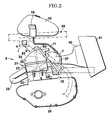
- FIG. 2 is a side view of relevant parts of an internal-combustion engine to which the drive circuit according to the present embodiment is connected.
- an ECU (Electronic Control Unit) 1 includes a CPU (Central Processing Unit) 2 that is a microcomputer, an ignition circuit 3 having incorporated therein a switching element, such as a transistor, that is operated under control of the CPU 2, and a drive circuit 4 having incorporated therein a switching element, such as a transistor, that is operated under control of the CPU 2.
- the ECU 1 is electrically connected to an ignition plug 6 and a fuel injection device 7 respectively provided in an internal-combustion engine 5.
- the CPU 2 includes an arithmetic processing device (not shown) and necessary memory devices and controls the entire operations of the internal-combustion engine 5.
- the ignition circuit 3 is electrically connected to the ignition plug 6 provided in the internal-combustion engine 5 by an electric wire 8.
- the ignition circuit 3 and an ignition coil IG are electrically connected by an electric wire 8a, where the ignition coil IG generates a high-voltage secondary voltage, which is an ignition voltage generated by a switching operation of the ignition circuit 3.
- the ignition coil IG and the ignition plug 6 are electrically connected by an electric wire 8b, and thus the ignition circuit 3 is electrically connected to the ignition plug 6.
- a secondary voltage generated by the ignition coil IG is applied to the ignition plug 6, and an ignition spark is applied to fuel and air mixture in a combustion chamber (not shown) in the internal-combustion engine 5.
- An ignition-voltage generating device for generating an ignition voltage is not limited to an ignition coil, and a capacitor electrically connected to a power generator or the like that is separately provided in an internal-combustion engine can be also used.
- the drive circuit 4 is electrically connected to the fuel injection device 7 provided in the internal-combustion engine 5 by an electric wire 9.
- a fuel pump 10 is connected to the fuel injection device 7 via a fuel pipe 11 such that the fuel pump 10 can freely supply fuel with a constant high pressure level, and the fuel pump 10 is electrically connected to the CPU 2 via an electric wire 12 and the drive circuit 4.
- the fuel injection device 7 has an actuator (not shown) incorporated therein, operates the actuator by a switching operation of the drive circuit 4, and injects fuel supplied from the fuel pump 10 from a nozzle (not shown) provided at a tip end of the fuel injection device 7 to the vicinity of the combustion chamber (not shown) in the internal-combustion engine 5.
- the fuel injection device 7 can also employ a configuration in which fuel is directly injected into the combustion chamber in the internal-combustion engine 5.
- a so-called power semiconductor device such as a power transistor, a power MOSFET (Metal-Oxide Semiconductor Field-Effect Transistor), an IGBT (Insulated Gate Bipolar Transistor), a BSIT (Bipolar mode Static Induction Transistor) is used.
- a load is the ignition coil IG or the fuel injection device 7
- the switching element is given high breakdown withstanding capability so as to have sufficient surge withstanding capability to a counter-electromotive force at the time of turning it off.
- examples of the configuration of having high breakdown withstanding capability include a configuration having a zener diode added thereto or that reduces a parasitic diode.
- various input circuits 14 to which a detection signal from various sensors 13 arranged in the internal-combustion engine 5 is input are provided; however, for convenience' sake, one sensor 13 and one input circuit 14 are shown in FIG. 1 .
- the internal-combustion engine 5 includes a crank case 20 that accommodates a crank (not shown) and a cylinder 21 having a combustion chamber (not shown).
- the cylinder 21 includes a cylinder block 22, a cylinder head 23, and a head cover 24 to have them directed upward from the crank case 20, and the cylinder 21 is typically arranged to be upright.
- a combustion chamber is formed in the cylinder block 22.
- An exhaust passage 26 communicated with an exhaust pipe 25 and a suction passage 28 communicated with a throttle body 27 are formed in the cylinder head 23, and the ignition plug 6 is arranged to face a combustion chamber of the cylinder block 22.
- An air cleaner 41 is communicated with the throttle body 27 via a communication pipe 40.
- a fuel tank 30 is arranged at an upper part of the head cover 24, and the fuel tank 30 supports the fuel pump 10 communicated with fuel stored therein.
- the fuel pump 10 can freely supply fuel with a constant high pressure level to the fuel injection device 7 provided in the throttle body 27 via the fuel pipe 11. While the electric wire 9 that electrically connects the drive circuit 4 and the fuel injection device 7 is wired along the fuel pipe 11, for convenience' sake, the electric wire 9 is not shown in FIG. 2 .
- the ECU 1 including the CPU 2, the ignition circuit 3, the drive circuit 4, and the input circuit 14, as well as the internal-combustion engine 5 and the fuel tank 30, are supported by a frame 50, which is a framework member of a vehicle.
- a frame 50 which is a framework member of a vehicle.
- the drive circuit 4 and the like has to be arranged in a narrow space above the cylinder head 23 of the internal-combustion engine 5 and around the fuel tank 30.
- the electric wire 8b that extends upward from the insertion hole 29 of the cylinder head 23 and electrically connects the ignition coil IG and the ignition plug 6 is routed while being close to the drive circuit 4.
- the CPU 2, the ignition circuit 3, and the input circuit 14 are not shown in FIG. 2 .
- the actuator of the fuel injection device 7 electrically connected to the drive circuit 4 via the electric wire 9 is operated by a switching operation of the drive circuit 4, and fuel is injected from a nozzle formed at a tip end of the fuel injection device 7 to the inside of the throttle body 27 with a predetermined time interval. Subsequently, the fuel injected in this way is mixed with air introduced from the communication pipe 40, and then supplied to a combustion chamber formed in the cylinder block 22 through the suction passage 28.
- the ignition coil IG generates a high-voltage secondary voltage as an ignition voltage
- the secondary voltage is applied to the ignition plug 6 arranged to face the combustion chamber of the cylinder block 22 via the electric wire 8b that electrically connects the ignition coil IG and the ignition plug 6.
- the ignition plug 6 having applied the secondary voltage in this way applies ignition spark to a mixture of fuel and air present in the combustion chamber of the cylinder block 22.
- FIG. 3 is a waveform diagram showing a secondary voltage generated in a secondary coil of an ignition coil under control of a microcomputer of the electronic control unit according to the present embodiment, where the horizontal axis represents a time T and the vertical axis represents a voltage V.
- FIG. 4 is a schematic diagram of an equivalent circuit showing a relationship between a drive circuit and an electric wire that electrically connects an ignition coil and an ignition plug in the present embodiment.
- FIG. 5 is a graph showing a coupling electrostatic capacity between a drive circuit and an electric wire that electrically connects an ignition coil and an ignition plug in the present embodiment.
- a secondary voltage generated by the ignition coil IG kept its normality as it reached to a predetermined level of high pressure at a time T1 and then attenuated afterwards, even when a driver of a vehicle felt strangeness during driving.
- fuel supplied to the fuel injection device 7 from the fuel pump 10 via the fuel pipe 11 under control of the CPU 2 kept its normality as it was at a predetermined level of high pressure, even when a driver of a vehicle felt strangeness during driving.
- the electric wire 8b that electrically connects the ignition coil IG and the ignition plug 6 is wired as it is inserted into the head cover 24 of the cylinder 21, which is positioned directly below the frame 50 and arranged to be upright. Therefore, the electric wire 8b and the drive circuit 4 tend to be arranged close to each other. As the electric wire 8b and the drive circuit 4 are arranged to be unnecessarily close to each other, it is thought that this tendency is the cause of a phenomenon of occurrence of strangeness in a vehicle during driving.
- the above result means that, when the electric wire 8b that electrically connects the ignition coil IG and the ignition plug 6 and the drive circuit 4 that is electrically connected to the fuel injection device 7 via the electric wire 9 are arranged to be close to each other, such that the distance (the shortest distance) therebetween is typically 5 cm or less, an electric field caused by a high-voltage secondary voltage flowing in the electric wire 8b generates a surge voltage that exceeds the tolerance of a switching element of the drive circuit 4 that is designed to have high tolerance. It is thought that this phenomenon makes operations of the switching element unstable, and the switching element is damaged in extreme cases.
- the electric wire 8b has a metal core 8c such as a copper wire, an outer layer thereof is coated by a sheath 8d that is an electrical insulator made of resin or the like, and electrically connects the ignition coil IG and the ignition plug 6.
- the surge voltage is generated by a high-voltage secondary voltage flowing in the metal core 8c of the electric wire 8b, because naturally there is a limitation in the tolerance of the drive circuit 4, although it is designed to have high tolerance, if the surge voltage exceeds the tolerance of the drive circuit 4, the switching element thereof is influenced by the surge voltage.
- a metal wire or the like is mixed in the sheath 8d of the electric wire 8b so as to block an electric field caused by a high-voltage secondary voltage flowing in the electric wire 8b, thereby preventing the electric field from leaking outside; however, if this process is employed, the configuration of the electric wire 8b is complicated and it becomes a factor of increasing the weight and cost of the electric wire 8b.
- the electric wire 8b it is preferable that such a complicated configuration is not employed, the metal core 8c such as a copper wire is included therein, and a simple configuration such that a metal wire or the like is not mixed on the outer layer and it is coated by a single layer of the sheath 8d made of resin or the like is maintained.
- Equation 2 was used to read the frequency f of a secondary voltage and the maximum voltage Vng from a characteristic diagram such as FIG. 3 , f and Vng were set as 25 ⁇ 10 7 (Hz) and 2 ⁇ 10 4 (V), respectively, the input impedance Zi of the drive circuit 4 was measured as 1274 ( ⁇ ), and the electrostatic capacity Cm (F) in a case where air was present between the electric wire 8b and the drive circuit 4 was 2.1 ⁇ 10 13 (F) to calculate the surge voltage Vni generated in the drive circuit 4, the value was 42 (V), and it resulted to be lower than 60 (V), which was the tolerance voltage of the drive circuit 4.
- the electrostatic capacity Cm in a case where there is air between the sheath 8d of the electric wire 8b and the electric wire 9 can be obtained from the graph shown in FIG 5 .
- the diameter "a" of the metal core 8c of the electric wire 8b is set as 1 (mm) and a diameter including the sheath 8d of the electric wire 8b is set as 7 (mm)
- the distance d between the surface of the sheath 8d of the electric wire 8b and the drive circuit 4 is 5 (cm).
- Equation 2 As the electrostatic capacity Cm in a case where there is air between the sheath 8d of the electric wire 8b and the electric wire 9 is determined so that the surge voltage Vni generated in the drive circuit 4 becomes equal to or larger than the tolerance voltage of the drive circuit 4, and then the distance d between the surface of the sheath 8d of the electric wire 8b and the drive circuit 4 is obtained based on the determined electrostatic capacity Cm, it is possible to determine the shortest distance d allowed between the surface of the sheath 8d of the electric wire 8b and the drive circuit 4, and then an arrangement position where the drive circuit 4 can be arranged with respect to the electric wire 8b that electrically connects an ignition coil and the ignition plug 6 can be determined.
- the drive circuit 4 is supported in a limited space along with the CPU 2, the internal-combustion engine 5, the fuel tank 30 and the like by the frame 50 within the ECU 1, and the electric wire 8b is inserted into the insertion hole 29 of the head cover 24 of the cylinder 21, which is positioned directly below the frame 50 and arranged to be upright and then routed, so that the electric wire 8b electrically connects the ignition coil IG and the ignition plug 6. Accordingly, each of the arrangement flexibility of the drive circuit 4, that of both ends of the electric wire 8b, and that within the head cover 24 of the electric wire 8b is limited.
- a part of the electric wire 8b protruding upward from the insertion hole 29 of the head cover 24 needs to be close to an upper portion of the head cover 24. That is, setting the total length of the electric wire 8b having its both ends defined by the ignition coil IG and the ignition plug 6 as a length required to bring a part of the electric wire 8b protruding upward from the insertion hole 29 of the head cover 24 to be close to an upper portion of the head cover 24 is preferable as a simple and secure configuration.
- the configuration becomes complicated it is also possible to hold the electric wire 8b by a holding member (not shown).
- a holding member not shown
- the shortest distance d between the electric wire 8b and the drive circuit 4 is securely maintained by providing a concave portion on an upper portion of the head cover 24 more intentionally and routing the electric wire 8b while accommodating it in the concave portion.
- FIG. 6 is a cross-sectional view showing a structure in which the microcomputer, the drive circuit and the like according to the present embodiment are arranged in the same package and stacked therein.
- the drive circuit 4 electrically connected to the fuel injection device 7 by the electric wire 9
- the various input circuits 14 to which a detection signal from the various sensors 13 is input, and the CPU 2 are configured to be sealed in a same package PK such as a casing and to be integrated with each other, and these elements are mounted on a desired support body SB so as to be fixed in a vehicle and the like.
- the package PK is a resin seal, and it is molded by a transfer molding method and the like.
- the distance d can be set by using a distance between the surface of the sheath 8d of the electric wire 8b and the package PK having the drive circuit 4 and the like and the CPU 2 sealed therein.
- the drive circuit 4 electrically connected to the fuel injection device 7 provided in the internal-combustion engine 5 by the electric wire 9 has been explained as an example of an electric circuit that is influenced by an electric field generated by the electric wire 8b that electrically connects an ignition coil and the ignition plug 6; however, it is needless to mention that, as for other types of semiconductor circuits, a spatial electrostatic capacity is set to determine the position of the circuit in a similar manner to that described above.
- an electric field caused by an electric current flowing in an electric wire that electrically connects an ignition-voltage generating device and an ignition plug induces a surge voltage to a drive circuit via an electrostatic capacity between a drive circuit and an electric wire
- the shortest distance between a drive circuit and an electric wire is set such that the surge voltage becomes equal to or lower than a predetermined surge withstanding capability with which a semiconductor power device of a drive circuit is configured to have high breakdown withstanding capability. Therefore, the surge voltage can be securely reduced with a simple configuration without having even higher breakdown withstanding capability or employing an additional configuration to other electric components or the like that induce the surge voltage, and it is possible to securely prevent the drive circuit from being influenced by an unnecessary surge voltage.
- the entirety of a device configuration can be made compact while securely preventing the drive circuit from being influenced by an unnecessary surge voltage.
- the present invention can provide an arrangement structure for a semiconductor circuit such as a drive circuit that can absorb a surge voltage securely with a simple configuration, without causing the semiconductor circuit to have even higher breakdown withstanding capability or employing an additional configuration to other electric components or the like that induce a surge voltage. Therefore, the present invention is expected to be widely applicable to a drive device for electric components of a vehicle and the like because of its general-purpose and universal characteristics.
Landscapes
- Engineering & Computer Science (AREA)
- Chemical & Material Sciences (AREA)
- Combustion & Propulsion (AREA)
- Mechanical Engineering (AREA)
- General Engineering & Computer Science (AREA)
- Ignition Installations For Internal Combustion Engines (AREA)
- Electrical Control Of Air Or Fuel Supplied To Internal-Combustion Engine (AREA)
- Fuel-Injection Apparatus (AREA)
Abstract
Description
- The present invention relates to an arrangement structure for a drive circuit, and more particularly relates to an arrangement structure for a drive circuit for fuel injection of an internal-combustion engine.
- In recent years, more sophisticated functions of various electric components incorporated in a vehicle such as a car have been demanded, and there has been a recent trend that various drive circuits are used under control of an in-vehicle microcomputer and control of operations of the drive circuits are executed in a precise manner.
- In many cases, these electric components are an inductance load having a coil such as a motor or an actuator incorporated therein, and when a drive circuit of the inductance load is operated and an electric component is turned off, there is a case where a surge voltage having a counter-electromotive force is applied on the drive circuit. Such a surge voltage to the drive circuit is a high voltage in many cases, and thus it is necessary to set that the breakdown withstanding capability of the drive circuit to the surge voltage to be a large value with some margin.
-
Patent Document 1 relates to an ignition device for an internal-combustion engine including acontrol IC 22, and discloses a configuration such that thecontrol IC 22 includes aprotection circuit 25 that protects a control circuit from high voltage surge such as static electricity and ignition noise as well as aninternal control circuit 23. Theprotection circuit 25 includes elements such as anNPN transistor 30 formed by an n- layer 26 stacked on a p- layer 27, a p+ base region 29 formed on an n- layer, an n+ collector region 33 formed in a p+ base region, and an n+ emitter region 37 formed on an n- layer and overlapping with a p+ base region and the like. -
Patent Document 2 relates to an ignition device for an internal-combustion engine including acontrol circuit IC 3, and discloses a configuration such that thecontrol circuit IC 3 includes aprotection element 10 having anNPN transistor 13 in which a collector terminal is connected to a signal line to which an ignition signal in thecontrol circuit IC 3 is input and an emitter terminal is connected to a ground (GND), acondenser 14 present between a base and an emitter in theNPN transistor 13, and a parasitic diode 13a present between a collector and an emitter of theNPN transistor 13, and that a circuit part to which an ignition signal is input is protected from extraneous surge while avoiding size increase. -
- Patent Document 1: Japanese Patent Application Laid-open No.
2004-335979 - Patent Document 2: Japanese Patent Application Laid-open No.
2006-46256 - According to studies of the present inventors, in the configurations of
Patent Document 1 andPatent Document 2, theprotection circuit 25 or theprotection element 10 is provided to employ a configuration in which high breakdown withstanding capability is realized so that thecontrol IC 22 or thecontrol circuit IC 3 is protected from a surge voltage; however, when the configuration is implemented in a vehicle in practice, a surge voltage induced from other wires or electric components sometimes becomes larger than an assumed value, and thus there is a case where it is necessary to employ a configuration that can realize much higher breakdown withstanding capability. - Producing a semiconductor circuit with high breakdown withstanding capability to have even higher breakdown withstanding capability means developing a semiconductor circuit with a more unique configuration, and this development is not ideal as far as the time and cost-effectiveness are concerned.
- Furthermore, a technique of reducing a surge voltage by employing an additional configuration to other electric components or the like that induce the surge voltage of an unexpected value is also not ideal as far as the time and cost-effectiveness are concerned, because of an increase in the number of parts.
- That is, there has been desired a configuration related to a semiconductor circuit that can securely reduce a surge voltage with a simple configuration when a surge voltage induced from other wires or electric components is large, without causing the semiconductor device to have even higher breakdown withstanding capability or employing an additional configuration to the electric components or the like that induce the surge voltage.
- The present invention has been achieved in view of the above studies, and an object of the present invention is to provide an arrangement structure for a semiconductor circuit such as a drive circuit that can securely reduce a surge voltage with a simple configuration, without causing the semiconductor device to have even higher breakdown withstanding capability or employing an additional configuration to electric components or the like that induce a surge voltage.
- To achieve the above object, a first aspect of the present invention provides an arrangement structure for a drive circuit that comprises a drive circuit that can freely inject fuel from a fuel injection device provided in an internal-combustion engine to the internal-combustion engine under control of a microcomputer, and an electric wire that electrically connects an ignition-voltage generating device that can freely apply an ignition voltage to an ignition plug provided in the internal-combustion engine and the ignition plug, wherein the drive circuit includes a semiconductor power device that is configured to have high breakdown withstanding capability to have predetermined surge withstanding capability, and a shortest distance between the drive circuit and the electric wire is set such that an electric field caused by an electric current flowing in the electric wire induces a surge voltage to the drive circuit via an electrostatic capacity between the drive circuit and the electric wire, and the surge voltage becomes equal to or lower than the predetermined surge withstanding capability of the semiconductor power device.
- According to a second aspect of the present invention, in addition to the first aspect, when a frequency of the ignition voltage flowing in the electric wire is designated as f (Hz), a maximum voltage of the ignition voltage is designated as Vng (V), the electrostatic capacity in a case where air is present between the electric wire and the drive circuit is designated as Cm (F), an input impedance of the drive circuit is designated as Zi (Q), and the surge voltage generated in the drive circuit is designated as Vni (V), the shortest distance between the drive circuit and the electric wire is set by determining the electrostatic capacity between the drive circuit and the electric wire such that the surge voltage obtained from following equation (Equation 1) becomes equal to or lower than the predetermined surge withstanding capability of the semiconductor power device.

- According to a third aspect of the present invention, in addition to the first or second aspects, the drive circuit is arranged on an upper part of the internal-combustion engine, and the electric wire extends from an upper portion of the internal-combustion engine.
- According to a fourth aspect of the present invention, in addition to any one of the first to third aspects, the electric wire includes a metal core and a sheath coating around the metal core by resin.
- According to a fifth aspect of the present invention, in addition to any one of the first to fourth aspects, the drive circuit and the microcomputer are arranged in a same package.
- According to the arrangement structure for a drive circuit of the first aspect of the present invention, the shortest distance between the drive circuit and the electric wire is set such that an electric field caused by an electric current flowing in the electric wire that electrically connects the ignition-voltage generating device and the ignition plug induces a surge voltage to the drive circuit via an electrostatic capacity between the drive circuit and the electric wire, and the surge voltage becomes equal to or lower than predetermined surge withstanding capability of the semiconductor power device of the drive circuit. Therefore, the surge voltage can be securely reduced with a simple configuration without having even higher breakdown withstanding capability or employing an additional configuration to other electric components or the like that induce the surge voltage, and it is possible to securely prevent the drive circuit from being influenced by an unnecessary surge voltage.
- According to the arrangement structure for a drive circuit of the second aspect of the present invention, the shortest distance between the drive circuit and the electric wire is set by determining the electrostatic capacity between the drive circuit and the electric wire that electrically connects the ignition-voltage generating device and the ignition plug such that the surge voltage obtained from the equation (Equation 1) becomes equal to or lower than the predetermined surge withstanding capability of the semiconductor power device. Therefore, the surge voltage can be securely reduced while the drive circuit is arranged based on a unified principle, and it is possible to securely prevent the drive circuit from being influenced by an unnecessary surge voltage.
- According to the arrangement structure for a drive circuit of the third aspect of the present invention, the drive circuit is arranged on an upper part of the internal-combustion engine, and the electric wire that electrically connects the ignition-voltage generating device and the ignition plug extends from an upper portion of the internal-combustion engine. Therefore, even when it is a configuration in which the drive circuit and the electric wire are close to each other, the surge voltage can be securely reduced, and thus it is possible to securely prevent the drive circuit from being influenced by an unnecessary surge voltage.
- According to the arrangement structure for a drive circuit of the fourth aspect of the present invention, even when the electric wire that electrically connects the ignition-voltage generating device and the ignition plug has a simple configuration such that the electric wire includes a metal core and a sheath coating around the metal core by resin, the surge voltage can be reduced. Therefore, even without employing any electric wire having a unique blocking structure, it is possible to securely prevent the drive circuit from being influenced by an unnecessary surge voltage.
- According to the arrangement structure for a drive circuit of the fifth aspect of the present invention, because the drive circuit and the microcomputer are arranged in a same package, the entirety of a device configuration can be made compact while securely preventing the drive circuit from being influenced by an unnecessary surge voltage.
-
- [
FIG. 1 ] A block diagram showing a connecting structure between an electronic control unit and an internal-combustion engine according to an embodiment of the present invention. - [
FIG. 2 ] A side view of relevant parts of an internal-combustion engine to which a drive circuit according to the embodiment is connected. - [
FIG. 3 ] A waveform diagram showing a secondary voltage generated in a secondary coil of an ignition coil under control of a microcomputer of the electronic control unit according to the embodiment. - [
FIG. 4 ] A schematic diagram of an equivalent circuit showing a relationship between the drive circuit according to the embodiment and an electric wire that electrically connects an ignition coil and an ignition plug. - [
FIG. 5 ] A graph showing a coupling electrostatic capacity between the drive circuit according to the embodiment and an electric wire that electrically connects an ignition coil and an ignition plug. - [
FIG. 6 ] A cross-sectional view showing a structure in which the microcomputer, the drive circuit and the like according to the embodiment are arranged in the same package and stacked therein. - An arrangement structure for a drive circuit according to an embodiment of the present invention will be explained below in detail with reference to the accompanying drawings while exemplifying a case of controlling fuel injection of an internal-combustion engine.
- First, configurations of the periphery of a drive circuit according to the present embodiment are explained below in detail with reference to
FIG. 1 andFIG. 2 . -
FIG. 1 is a block diagram showing a connecting structure between an electronic control unit and an internal-combustion engine according to the present embodiment.FIG. 2 is a side view of relevant parts of an internal-combustion engine to which the drive circuit according to the present embodiment is connected. - As shown in
FIG. 1 , an ECU (Electronic Control Unit) 1 includes a CPU (Central Processing Unit) 2 that is a microcomputer, anignition circuit 3 having incorporated therein a switching element, such as a transistor, that is operated under control of theCPU 2, and adrive circuit 4 having incorporated therein a switching element, such as a transistor, that is operated under control of theCPU 2. The ECU 1 is electrically connected to anignition plug 6 and afuel injection device 7 respectively provided in an internal-combustion engine 5. TheCPU 2 includes an arithmetic processing device (not shown) and necessary memory devices and controls the entire operations of the internal-combustion engine 5. - Specifically, in the
ECU 1, theignition circuit 3 is electrically connected to theignition plug 6 provided in the internal-combustion engine 5 by anelectric wire 8. Specifically, as for theignition circuit 3, theignition circuit 3 and an ignition coil IG are electrically connected by anelectric wire 8a, where the ignition coil IG generates a high-voltage secondary voltage, which is an ignition voltage generated by a switching operation of theignition circuit 3. Furthermore, the ignition coil IG and theignition plug 6 are electrically connected by anelectric wire 8b, and thus theignition circuit 3 is electrically connected to theignition plug 6. A secondary voltage generated by the ignition coil IG is applied to theignition plug 6, and an ignition spark is applied to fuel and air mixture in a combustion chamber (not shown) in the internal-combustion engine 5. An ignition-voltage generating device for generating an ignition voltage is not limited to an ignition coil, and a capacitor electrically connected to a power generator or the like that is separately provided in an internal-combustion engine can be also used. - In the
ECU 1, thedrive circuit 4 is electrically connected to thefuel injection device 7 provided in the internal-combustion engine 5 by anelectric wire 9. Meanwhile, afuel pump 10 is connected to thefuel injection device 7 via afuel pipe 11 such that thefuel pump 10 can freely supply fuel with a constant high pressure level, and thefuel pump 10 is electrically connected to theCPU 2 via anelectric wire 12 and thedrive circuit 4. Thefuel injection device 7 has an actuator (not shown) incorporated therein, operates the actuator by a switching operation of thedrive circuit 4, and injects fuel supplied from thefuel pump 10 from a nozzle (not shown) provided at a tip end of thefuel injection device 7 to the vicinity of the combustion chamber (not shown) in the internal-combustion engine 5. Thefuel injection device 7 can also employ a configuration in which fuel is directly injected into the combustion chamber in the internal-combustion engine 5. - As a switching element in the
ignition circuit 3 and thedrive circuit 4, a so-called power semiconductor device such as a power transistor, a power MOSFET (Metal-Oxide Semiconductor Field-Effect Transistor), an IGBT (Insulated Gate Bipolar Transistor), a BSIT (Bipolar mode Static Induction Transistor) is used. Particularly in consideration of a fact that a load is the ignition coil IG or thefuel injection device 7, the switching element is given high breakdown withstanding capability so as to have sufficient surge withstanding capability to a counter-electromotive force at the time of turning it off. Although not limited thereto, examples of the configuration of having high breakdown withstanding capability include a configuration having a zener diode added thereto or that reduces a parasitic diode. - In the
ECU 1, in order to control theignition circuit 3 and thedrive circuit 4,various input circuits 14 to which a detection signal fromvarious sensors 13 arranged in the internal-combustion engine 5 is input, are provided; however, for convenience' sake, onesensor 13 and oneinput circuit 14 are shown inFIG. 1 . - As shown in
FIG. 2 , the internal-combustion engine 5 includes acrank case 20 that accommodates a crank (not shown) and acylinder 21 having a combustion chamber (not shown). Thecylinder 21 includes acylinder block 22, acylinder head 23, and ahead cover 24 to have them directed upward from thecrank case 20, and thecylinder 21 is typically arranged to be upright. - A combustion chamber is formed in the
cylinder block 22. Anexhaust passage 26 communicated with anexhaust pipe 25 and a suction passage 28 communicated with athrottle body 27 are formed in thecylinder head 23, and theignition plug 6 is arranged to face a combustion chamber of thecylinder block 22. Aninsertion hole 29 having inserted therein theelectric wire 8b, which is a so-called high-tension code that electrically connects the ignition coil IG supported at a lower part of thethrottle body 27 and theignition plug 6, is formed in thehead cover 24. An air cleaner 41 is communicated with thethrottle body 27 via acommunication pipe 40. - A
fuel tank 30 is arranged at an upper part of thehead cover 24, and thefuel tank 30 supports thefuel pump 10 communicated with fuel stored therein. Thefuel pump 10 can freely supply fuel with a constant high pressure level to thefuel injection device 7 provided in thethrottle body 27 via thefuel pipe 11. While theelectric wire 9 that electrically connects thedrive circuit 4 and thefuel injection device 7 is wired along thefuel pipe 11, for convenience' sake, theelectric wire 9 is not shown inFIG. 2 . - The
ECU 1 including theCPU 2, theignition circuit 3, thedrive circuit 4, and theinput circuit 14, as well as the internal-combustion engine 5 and thefuel tank 30, are supported by aframe 50, which is a framework member of a vehicle. Particularly in a vehicle such as a motorcycle, due to its design layout, there is a case where thedrive circuit 4 and the like has to be arranged in a narrow space above thecylinder head 23 of the internal-combustion engine 5 and around thefuel tank 30. In this case, there may be a state where theelectric wire 8b that extends upward from theinsertion hole 29 of thecylinder head 23 and electrically connects the ignition coil IG and theignition plug 6 is routed while being close to thedrive circuit 4. For convenience' sake, theCPU 2, theignition circuit 3, and theinput circuit 14 are not shown inFIG. 2 . - A combustion operation in the internal-
combustion engine 5 having the above configuration is explained below in detail. - As for supplying a mixture of fuel and air, while fuel with a constant high pressure level is supplied from the
fuel pump 10 to thefuel injection device 7 via thefuel pipe 11 under control of theCPU 2, the actuator of thefuel injection device 7 electrically connected to thedrive circuit 4 via theelectric wire 9 is operated by a switching operation of thedrive circuit 4, and fuel is injected from a nozzle formed at a tip end of thefuel injection device 7 to the inside of thethrottle body 27 with a predetermined time interval. Subsequently, the fuel injected in this way is mixed with air introduced from thecommunication pipe 40, and then supplied to a combustion chamber formed in thecylinder block 22 through the suction passage 28. - Meanwhile, as for ignition of the mixture, as the
ignition circuit 3 performs a switching operation under control of theCPU 2, the ignition coil IG generates a high-voltage secondary voltage as an ignition voltage, and the secondary voltage is applied to theignition plug 6 arranged to face the combustion chamber of thecylinder block 22 via theelectric wire 8b that electrically connects the ignition coil IG and theignition plug 6. Theignition plug 6 having applied the secondary voltage in this way applies ignition spark to a mixture of fuel and air present in the combustion chamber of thecylinder block 22. - Subsequently, the mixture of fuel and air in the combustion chamber of the
cylinder block 22 having applied ignition spark from theignition plug 6 as described above is combusted, thereby operating the internal-combustion engine 5. Exhaust gas generated after the combustion is discharged to outside via theexhaust passage 26 and theexhaust pipe 25 in this order. - As a series of operations of the internal-
combustion engine 5 as described above was repeated for a predetermined time, there was a case where a driver of a vehicle felt strangeness during driving, such as an output from the internal-combustion engine 5 varied from that of a desired output. - A phenomenon of occurrence of the strangeness during driving in a vehicle is examined below in detail.
-
FIG. 3 is a waveform diagram showing a secondary voltage generated in a secondary coil of an ignition coil under control of a microcomputer of the electronic control unit according to the present embodiment, where the horizontal axis represents a time T and the vertical axis represents a voltage V.FIG. 4 is a schematic diagram of an equivalent circuit showing a relationship between a drive circuit and an electric wire that electrically connects an ignition coil and an ignition plug in the present embodiment.FIG. 5 is a graph showing a coupling electrostatic capacity between a drive circuit and an electric wire that electrically connects an ignition coil and an ignition plug in the present embodiment. InFIG. 5 , as a diameter of a metal core in the electric wire that electrically connects an ignition coil and an ignition plug is denoted as "a" and a distance (a shortest distance) between a surface of a sheath of the electric wire and a drive circuit is denoted as "d", the horizontal axis is expressed as "d/a", and the vertical axis expresses an electrostatic capacity Cm in a case of assuming that air is present between the sheath of the electric wire and the drive circuit. - First, as shown in
FIG. 3 , when theignition circuit 3 performed a switching operation under control of theCPU 2, a secondary voltage generated by the ignition coil IG kept its normality as it reached to a predetermined level of high pressure at a time T1 and then attenuated afterwards, even when a driver of a vehicle felt strangeness during driving. - Also fuel supplied to the
fuel injection device 7 from thefuel pump 10 via thefuel pipe 11 under control of theCPU 2 kept its normality as it was at a predetermined level of high pressure, even when a driver of a vehicle felt strangeness during driving. - However, operations of the actuator of the
fuel injection device 7 electrically connected to thedrive circuit 4 via theelectric wire 9 under control of theCPU 2 tend to be unstable, and it is thought that this tendency is the cause of a case where a driver of a vehicle feels strangeness during driving, such as an output from the internal-combustion engine 5 varies from that of a desired output. - Furthermore, the cause of the unstableness of operations of the actuator of the
fuel injection device 7 is examined below in more detail. That is, when theelectric wire 8b that electrically connects the ignition coil IG and theignition plug 6 is made to contact with thedrive circuit 4 that is electrically connected to thefuel injection device 7 via theelectric wire 9, there is a phenomenon that not only operations of the actuator of thefuel injection device 7 but also a switching operation of thedrive circuit 4 are stopped, whereas operations of the actuator of thefuel injection device 7 and thedrive circuit 4 did not stop and maintained to be normal when theelectric wire 8b was separated from thedrive circuit 4 for approximately 5 cm. - Particularly, when the vehicle is a motorcycle, while the
drive circuit 4 is supported in a limited space along with theCPU 2, the internal-combustion engine 5, thefuel tank 30 and the like by theframe 50 within theECU 1, theelectric wire 8b that electrically connects the ignition coil IG and theignition plug 6 is wired as it is inserted into thehead cover 24 of thecylinder 21, which is positioned directly below theframe 50 and arranged to be upright. Therefore, theelectric wire 8b and thedrive circuit 4 tend to be arranged close to each other. As theelectric wire 8b and thedrive circuit 4 are arranged to be unnecessarily close to each other, it is thought that this tendency is the cause of a phenomenon of occurrence of strangeness in a vehicle during driving. - Specifically, when conditions of the
fuel injection device 7 and thedrive circuit 4 were checked as theelectric wire 8b is made to contact with thedrive circuit 4, there was no abnormality in thefuel injection device 7 and operations thereof as a single unit were normal; however, abnormality was observed in a switching element in thedrive circuit 4, and thedrive circuit 4 did not operate normally. In this case, as a single unit, no abnormality was observed in thefuel pump 10 that communicates with thefuel injection device 7. - The above result means that, when the
electric wire 8b that electrically connects the ignition coil IG and theignition plug 6 and thedrive circuit 4 that is electrically connected to thefuel injection device 7 via theelectric wire 9 are arranged to be close to each other, such that the distance (the shortest distance) therebetween is typically 5 cm or less, an electric field caused by a high-voltage secondary voltage flowing in theelectric wire 8b generates a surge voltage that exceeds the tolerance of a switching element of thedrive circuit 4 that is designed to have high tolerance. It is thought that this phenomenon makes operations of the switching element unstable, and the switching element is damaged in extreme cases. - Furthermore, a relationship between the
electric wire 8b and thedrive circuit 4 is examined with reference to an equivalent circuit shown inFIG. 4 . - Specifically, the
electric wire 8b has ametal core 8c such as a copper wire, an outer layer thereof is coated by asheath 8d that is an electrical insulator made of resin or the like, and electrically connects the ignition coil IG and theignition plug 6. - Between the
electric wire 8b and thedrive circuit 4, as far as there is no other constituent elements, air is present therebetween. When theelectric wire 8b and thedrive circuit 4 are arranged to be unnecessarily close to each other, in such an area where only air is present, an electric field caused by a high-voltage secondary voltage flowing in themetal core 8c of theelectric wire 8b is applied to a switching element of thedrive circuit 4 as the electric field transcends thesheath 8d of theelectric wire 8b, and a surge voltage is induced. - That is, while the surge voltage is generated by a high-voltage secondary voltage flowing in the
metal core 8c of theelectric wire 8b, because naturally there is a limitation in the tolerance of thedrive circuit 4, although it is designed to have high tolerance, if the surge voltage exceeds the tolerance of thedrive circuit 4, the switching element thereof is influenced by the surge voltage. - To reduce the surge voltage, it is possible that a metal wire or the like is mixed in the
sheath 8d of theelectric wire 8b so as to block an electric field caused by a high-voltage secondary voltage flowing in theelectric wire 8b, thereby preventing the electric field from leaking outside; however, if this process is employed, the configuration of theelectric wire 8b is complicated and it becomes a factor of increasing the weight and cost of theelectric wire 8b. In view of this problem, as for theelectric wire 8b, it is preferable that such a complicated configuration is not employed, themetal core 8c such as a copper wire is included therein, and a simple configuration such that a metal wire or the like is not mixed on the outer layer and it is coated by a single layer of thesheath 8d made of resin or the like is maintained. - Consequently, because an electric field caused by a high-voltage secondary voltage flowing in the
electric wire 8b propagates in a part of air between themetal core 8c of theelectric wire 8b and thedrive circuit 4, it is considered to be reasonable to actively utilize an electrostatic capacity in the air part between theelectric wire 8b and thedrive circuit 4 so as to employ a configuration of absorbing a surge voltage generated by the electric field. - When a frequency of a secondary voltage flowing in the
metal core 8c of theelectric wire 8b is designated as f (Hz), a maximum voltage of the secondary voltage flowing in themetal core 8c of theelectric wire 8b is designated as Vng (V), an electrostatic capacity in a case where air is present between thesheath 8d of theelectric wire 8b and thedrive circuit 4 is designated as Cm (F), an input impedance of thedrive circuit 4 is designated as Zi (Ω), and a surge voltage generated in thedrive circuit 4 is designated as Vni (V), the surge voltage Vni is expressed by the following equation (Equation 2).
- For example, as the equation (Equation 2) was used to read the frequency f of a secondary voltage and the maximum voltage Vng from a characteristic diagram such as
FIG. 3 , f and Vng were set as 25×107 (Hz) and 2×10⁴ (V), respectively, the input impedance Zi of thedrive circuit 4 was measured as 1274 (Ω), and the electrostatic capacity Cm (F) in a case where air was present between theelectric wire 8b and thedrive circuit 4 was 2.1×10¹³ (F) to calculate the surge voltage Vni generated in thedrive circuit 4, the value was 42 (V), and it resulted to be lower than 60 (V), which was the tolerance voltage of thedrive circuit 4. - At this time, the electrostatic capacity Cm in a case where there is air between the
sheath 8d of theelectric wire 8b and theelectric wire 9 can be obtained from the graph shown inFIG 5 . In this case, when the diameter "a" of themetal core 8c of theelectric wire 8b is set as 1 (mm) and a diameter including thesheath 8d of theelectric wire 8b is set as 7 (mm), the distance d between the surface of thesheath 8d of theelectric wire 8b and thedrive circuit 4 is 5 (cm). This result straightforwardly corresponds to a fact that, in an actual vehicle, when theelectric wire 8b is separated from thedrive circuit 4 for 5 cm, operations of an actuator of thefuel injection device 7 and thedrive circuit 4 do not stop and are maintained to be normal, and thus the driver of the vehicle does not feel any strangeness in his driving feeling. - Therefore, by using the equation (Equation 2), as the electrostatic capacity Cm in a case where there is air between the
sheath 8d of theelectric wire 8b and theelectric wire 9 is determined so that the surge voltage Vni generated in thedrive circuit 4 becomes equal to or larger than the tolerance voltage of thedrive circuit 4, and then the distance d between the surface of thesheath 8d of theelectric wire 8b and thedrive circuit 4 is obtained based on the determined electrostatic capacity Cm, it is possible to determine the shortest distance d allowed between the surface of thesheath 8d of theelectric wire 8b and thedrive circuit 4, and then an arrangement position where thedrive circuit 4 can be arranged with respect to theelectric wire 8b that electrically connects an ignition coil and theignition plug 6 can be determined. - The
drive circuit 4 is supported in a limited space along with theCPU 2, the internal-combustion engine 5, thefuel tank 30 and the like by theframe 50 within theECU 1, and theelectric wire 8b is inserted into theinsertion hole 29 of thehead cover 24 of thecylinder 21, which is positioned directly below theframe 50 and arranged to be upright and then routed, so that theelectric wire 8b electrically connects the ignition coil IG and theignition plug 6. Accordingly, each of the arrangement flexibility of thedrive circuit 4, that of both ends of theelectric wire 8b, and that within thehead cover 24 of theelectric wire 8b is limited. Therefore, in order to realize the shortest distance d, in an area between thedrive circuit 4 and thehead cover 24, a part of theelectric wire 8b protruding upward from theinsertion hole 29 of thehead cover 24 needs to be close to an upper portion of thehead cover 24. That is, setting the total length of theelectric wire 8b having its both ends defined by the ignition coil IG and theignition plug 6 as a length required to bring a part of theelectric wire 8b protruding upward from theinsertion hole 29 of thehead cover 24 to be close to an upper portion of thehead cover 24 is preferable as a simple and secure configuration. In order to securely bring the part of theelectric wire 8b to an upper portion of thehead cover 24, although the configuration becomes complicated, it is also possible to hold theelectric wire 8b by a holding member (not shown). Alternatively, it is also possible that the shortest distance d between theelectric wire 8b and thedrive circuit 4 is securely maintained by providing a concave portion on an upper portion of thehead cover 24 more intentionally and routing theelectric wire 8b while accommodating it in the concave portion. - An implementing configuration between the
CPU 2 and theignition circuit 3, thedrive circuit 4, and theinput circuit 14 in the above configuration is explained below also with reference toFIG. 6 . -
FIG. 6 is a cross-sectional view showing a structure in which the microcomputer, the drive circuit and the like according to the present embodiment are arranged in the same package and stacked therein. - As shown in
FIG. 6 , theignition circuit 3 electrically connected to theignition plug 6 by theelectric wire 8, thedrive circuit 4 electrically connected to thefuel injection device 7 by theelectric wire 9, thevarious input circuits 14 to which a detection signal from thevarious sensors 13 is input, and theCPU 2 are configured to be sealed in a same package PK such as a casing and to be integrated with each other, and these elements are mounted on a desired support body SB so as to be fixed in a vehicle and the like. For example, the package PK is a resin seal, and it is molded by a transfer molding method and the like. With this configuration, a configuration of a driver device including theignition circuit 3, thedrive circuit 4, theinput circuit 14, and theCPU 2 can be made compact. - To specify the distance d between the surface of the
sheath 8d of theelectric wire 8b and thedrive circuit 4 in a case of having a configuration in which thedrive circuit 4 and the like and theCPU 2 are sealed in the package PK and are integrated with each other as described above, because thedrive circuit 4 is hidden in the package PK and thus it cannot be observed from outside, for convenience, the distance d can be set by using a distance between the surface of thesheath 8d of theelectric wire 8b and the package PK having thedrive circuit 4 and the like and theCPU 2 sealed therein. - In the present embodiment, the
drive circuit 4 electrically connected to thefuel injection device 7 provided in the internal-combustion engine 5 by theelectric wire 9 has been explained as an example of an electric circuit that is influenced by an electric field generated by theelectric wire 8b that electrically connects an ignition coil and theignition plug 6; however, it is needless to mention that, as for other types of semiconductor circuits, a spatial electrostatic capacity is set to determine the position of the circuit in a similar manner to that described above. - According to the above configuration, an electric field caused by an electric current flowing in an electric wire that electrically connects an ignition-voltage generating device and an ignition plug induces a surge voltage to a drive circuit via an electrostatic capacity between a drive circuit and an electric wire, and the shortest distance between a drive circuit and an electric wire is set such that the surge voltage becomes equal to or lower than a predetermined surge withstanding capability with which a semiconductor power device of a drive circuit is configured to have high breakdown withstanding capability. Therefore, the surge voltage can be securely reduced with a simple configuration without having even higher breakdown withstanding capability or employing an additional configuration to other electric components or the like that induce the surge voltage, and it is possible to securely prevent the drive circuit from being influenced by an unnecessary surge voltage.
- By deciding an electrostatic capacity of a drive circuit and an electric wire that connects an ignition-voltage generating device and an ignition plug such that a surge voltage obtained by the equation (Equation 2) becomes equal to or lower than a predetermined surge withstanding capability, because the shortest distance between the drive circuit and the electric wire is set, the surge voltage can be securely reduced while the drive circuit is arranged based on a unified principle, and it is possible to securely prevent the drive circuit from being influenced by an unnecessary surge voltage.
- Even if it is a configuration in which a drive circuit is arranged on an upper portion of an internal-combustion engine, an electric wire that electrically connects an ignition-voltage generating device and an ignition plug extends from an upper part of the internal-combustion engine, and the drive circuit and the electric wire become close to each other, a surge voltage can be securely reduced, and thus it is possible to securely prevent the drive circuit from being influenced by an unnecessary surge voltage.
- Even if it is a simple configuration in which an electric wire that electrically connects an ignition-voltage generating device and an ignition plug has a metal core and a sheath coating around the metal core by resin, a surge voltage can be reduced. Therefore, even without employing any electric wire having a unique blocking structure, it is possible to securely prevent the drive circuit from being influenced by an unnecessary surge voltage.
- By arranging a drive circuit and a microcomputer in the same package, the entirety of a device configuration can be made compact while securely preventing the drive circuit from being influenced by an unnecessary surge voltage.
- In the present invention, the types, arrangements, and numbers of constituent elements are not limited to those described in the above embodiment, and it is needless to mention that changes can be appropriately made without departing from the scope of the invention, such as replacing these constituent elements with other elements having equivalent operational effects.
- As explained above, the present invention can provide an arrangement structure for a semiconductor circuit such as a drive circuit that can absorb a surge voltage securely with a simple configuration, without causing the semiconductor circuit to have even higher breakdown withstanding capability or employing an additional configuration to other electric components or the like that induce a surge voltage. Therefore, the present invention is expected to be widely applicable to a drive device for electric components of a vehicle and the like because of its general-purpose and universal characteristics.
Claims (5)
- An arrangement structure for a drive circuit, comprising:a drive circuit that can freely inject fuel from a fuel injection device provided in an internal-combustion engine to the internal-combustion engine under control of a microcomputer; andan electric wire that electrically connects an ignition-voltage generating device that can freely apply an ignition voltage to an ignition plug provided in the internal-combustion engine and the ignition plug, whereinthe drive circuit includes a semiconductor power device that is configured to have high breakdown withstanding capability to have predetermined surge withstanding capability, anda shortest distance between the drive circuit and the electric wire is set such that an electric field caused by an electric current flowing in the electric wire induces a surge voltage to the drive circuit via an electrostatic capacity between the drive circuit and the electric wire, and the surge voltage becomes equal to or lower than the predetermined surge withstanding capability of the semiconductor power device.
- The arrangement structure for a drive circuit according to claim 1, wherein when a frequency of the ignition voltage flowing in the electric wire is designated as f (Hz), a maximum voltage of the ignition voltage is designated as Vng (V), the electrostatic capacity in a case where air is present between the electric wire and the drive circuit is designated as Cm (F), an input impedance of the drive circuit is designated as Zi (12), and the surge voltage generated in the drive circuit is designated as Vni (V), the shortest distance between the drive circuit and the electric wire is set by determining the electrostatic capacity between the drive circuit and the electric wire such that the surge voltage obtained from following equation (Equation 3) becomes equal to or lower than the predetermined surge withstanding capability of the semiconductor power device.

- The arrangement structure for a drive circuit according to claim 1, wherein
the drive circuit is arranged on an upper part of the internal-combustion engine, and
the electric wire extends from an upper portion of the internal-combustion engine. - The arrangement structure for a drive circuit according to claim 1, wherein the electric wire includes a metal core and a sheath coating around the metal core by resin.
- The arrangement structure for a drive circuit according to claim 1, wherein the drive circuit and the microcomputer are arranged in a same package.
Applications Claiming Priority (2)
| Application Number | Priority Date | Filing Date | Title |
|---|---|---|---|
| JP2010070998 | 2010-03-25 | ||
| PCT/JP2011/056022 WO2011118445A1 (en) | 2010-03-25 | 2011-03-15 | Structural arrangement for drive circuit |
Publications (2)
| Publication Number | Publication Date |
|---|---|
| EP2551510A1 true EP2551510A1 (en) | 2013-01-30 |
| EP2551510A4 EP2551510A4 (en) | 2016-08-24 |
Family
ID=44673002
Family Applications (1)
| Application Number | Title | Priority Date | Filing Date |
|---|---|---|---|
| EP11759251.9A Withdrawn EP2551510A4 (en) | 2010-03-25 | 2011-03-15 | STRUCTURAL MOUNTING FOR PILOT CIRCUIT |
Country Status (5)
| Country | Link |
|---|---|
| US (1) | US20120318240A1 (en) |
| EP (1) | EP2551510A4 (en) |
| JP (1) | JP5374637B2 (en) |
| BR (1) | BR112012024331A2 (en) |
| WO (1) | WO2011118445A1 (en) |
Family Cites Families (12)
| Publication number | Priority date | Publication date | Assignee | Title |
|---|---|---|---|---|
| JPS5862368A (en) * | 1981-10-12 | 1983-04-13 | Nec Home Electronics Ltd | Engine ignition control device |
| JPS58106118A (en) * | 1981-12-18 | 1983-06-24 | Honda Motor Co Ltd | Introducing device of secondary air in autobicycle |
| JPH05164010A (en) * | 1991-12-10 | 1993-06-29 | Honda Motor Co Ltd | Battery-less electronic fuel injection control device for engine |
| DE69525986T2 (en) * | 1994-05-06 | 2002-12-19 | Cummins Engine Co Inc | Method and device for the electronic control of a storage fuel system |
| JPH08261107A (en) * | 1995-03-24 | 1996-10-08 | Aisan Ind Co Ltd | Fuel injection device |
| JP3492077B2 (en) * | 1996-04-26 | 2004-02-03 | トヨタ自動車株式会社 | Control device for internal combustion engine |
| JP3835058B2 (en) * | 1999-05-12 | 2006-10-18 | スズキ株式会社 | Outboard motor electrical component mounting structure |
| JP2002015916A (en) * | 2000-06-27 | 2002-01-18 | Mitsubishi Electric Corp | Solenoid drive |
| JP4380215B2 (en) * | 2003-05-12 | 2009-12-09 | 株式会社デンソー | Control IC |
| JP4360299B2 (en) * | 2004-08-06 | 2009-11-11 | 株式会社デンソー | Ignition device for internal combustion engine |
| JP2006097668A (en) * | 2004-09-28 | 2006-04-13 | San Jidosha Kogyo:Kk | Spark plug cord |
| JP5049740B2 (en) * | 2007-10-25 | 2012-10-17 | シャープ株式会社 | Semiconductor laser protection circuit, optical pickup device, optical module, and information recording / reproducing device |
-
2011
- 2011-03-15 BR BR112012024331A patent/BR112012024331A2/en not_active IP Right Cessation
- 2011-03-15 US US13/580,579 patent/US20120318240A1/en not_active Abandoned
- 2011-03-15 JP JP2012506949A patent/JP5374637B2/en not_active Expired - Fee Related
- 2011-03-15 WO PCT/JP2011/056022 patent/WO2011118445A1/en not_active Ceased
- 2011-03-15 EP EP11759251.9A patent/EP2551510A4/en not_active Withdrawn
Non-Patent Citations (1)
| Title |
|---|
| See references of WO2011118445A1 * |
Also Published As
| Publication number | Publication date |
|---|---|
| US20120318240A1 (en) | 2012-12-20 |
| EP2551510A4 (en) | 2016-08-24 |
| WO2011118445A1 (en) | 2011-09-29 |
| BR112012024331A2 (en) | 2016-05-24 |
| JPWO2011118445A1 (en) | 2013-07-04 |
| JP5374637B2 (en) | 2013-12-25 |
Similar Documents
| Publication | Publication Date | Title |
|---|---|---|
| US6378514B1 (en) | Igniter for internal combustion engine | |
| JP3968711B2 (en) | Ignition device for internal combustion engine and igniter thereof | |
| JP5063572B2 (en) | In-vehicle electronic control unit | |
| JP4482782B2 (en) | Control device for vehicle alternator | |
| US7418956B2 (en) | Ignition apparatus for an internet combustion engine | |
| US20190252872A1 (en) | Device for protecting an electronic computer against a short circuit | |
| CN100550379C (en) | Semiconductor devices using backside high withstand voltage integrated circuits | |
| EP2551510A1 (en) | Structural arrangement for drive circuit | |
| JP5037992B2 (en) | Igniter | |
| CN111051686A (en) | ignition device | |
| US12104565B2 (en) | Igniter and engine ignition device | |
| CN108630417B (en) | Ignition coil for internal combustion engine | |
| JP2005255032A (en) | Vehicle occupant protection device | |
| CN111664043A (en) | Semiconductor integrated circuit | |
| US7004155B2 (en) | Ignition apparatus for internal combustion engine | |
| US20070246029A1 (en) | Ignition coil and ignition device for internal combustion engine | |
| US20250330154A1 (en) | Driver circuit | |
| JP3831640B2 (en) | Internal combustion engine ignition device | |
| JP2006108630A (en) | Ignition coil and manufacturing method thereof | |
| JP5847111B2 (en) | Ignition device for internal combustion engine | |
| JP2008133826A (en) | Igniter for ignition device for internal combustion engine | |
| KR20130007070A (en) | Device for detecting brake-down of battery cables for vehicles | |
| JP3831641B2 (en) | Internal combustion engine ignition device | |
| JP2022176842A (en) | integrated circuit | |
| Estl et al. | Smart IGBTs for advanced distribution ignition systems |
Legal Events
| Date | Code | Title | Description |
|---|---|---|---|
| PUAI | Public reference made under article 153(3) epc to a published international application that has entered the european phase |
Free format text: ORIGINAL CODE: 0009012 |
|
| 17P | Request for examination filed |
Effective date: 20120928 |
|
| AK | Designated contracting states |
Kind code of ref document: A1 Designated state(s): AL AT BE BG CH CY CZ DE DK EE ES FI FR GB GR HR HU IE IS IT LI LT LU LV MC MK MT NL NO PL PT RO RS SE SI SK SM TR |
|
| DAX | Request for extension of the european patent (deleted) | ||
| RIC1 | Information provided on ipc code assigned before grant |
Ipc: F02P 11/00 20060101AFI20160713BHEP Ipc: F02D 41/00 20060101ALI20160713BHEP |
|
| RA4 | Supplementary search report drawn up and despatched (corrected) |
Effective date: 20160722 |
|
| STAA | Information on the status of an ep patent application or granted ep patent |
Free format text: STATUS: EXAMINATION IS IN PROGRESS |
|
| 17Q | First examination report despatched |
Effective date: 20170518 |
|
| STAA | Information on the status of an ep patent application or granted ep patent |
Free format text: STATUS: THE APPLICATION IS DEEMED TO BE WITHDRAWN |
|
| 18D | Application deemed to be withdrawn |
Effective date: 20181002 |