EP2551241A1 - Water treatment device and process - Google Patents
Water treatment device and process Download PDFInfo
- Publication number
- EP2551241A1 EP2551241A1 EP11175401A EP11175401A EP2551241A1 EP 2551241 A1 EP2551241 A1 EP 2551241A1 EP 11175401 A EP11175401 A EP 11175401A EP 11175401 A EP11175401 A EP 11175401A EP 2551241 A1 EP2551241 A1 EP 2551241A1
- Authority
- EP
- European Patent Office
- Prior art keywords
- membrane
- membranes
- water
- channels
- channel
- Prior art date
- Legal status (The legal status is an assumption and is not a legal conclusion. Google has not performed a legal analysis and makes no representation as to the accuracy of the status listed.)
- Withdrawn
Links
- XLYOFNOQVPJJNP-UHFFFAOYSA-N water Substances O XLYOFNOQVPJJNP-UHFFFAOYSA-N 0.000 title claims abstract description 32
- 238000000034 method Methods 0.000 title claims abstract description 6
- 239000012528 membrane Substances 0.000 claims abstract description 73
- 230000001699 photocatalysis Effects 0.000 claims abstract description 23
- 230000003287 optical effect Effects 0.000 claims abstract description 11
- 238000001914 filtration Methods 0.000 claims abstract description 7
- 239000012465 retentate Substances 0.000 claims abstract description 7
- 239000012466 permeate Substances 0.000 claims abstract description 6
- 239000013307 optical fiber Substances 0.000 claims abstract description 4
- GWEVSGVZZGPLCZ-UHFFFAOYSA-N Titan oxide Chemical compound O=[Ti]=O GWEVSGVZZGPLCZ-UHFFFAOYSA-N 0.000 claims description 23
- 239000000463 material Substances 0.000 claims description 14
- 239000000835 fiber Substances 0.000 claims description 9
- 238000000108 ultra-filtration Methods 0.000 claims description 5
- 239000004408 titanium dioxide Substances 0.000 claims description 3
- 239000004020 conductor Substances 0.000 claims 1
- 239000003365 glass fiber Substances 0.000 claims 1
- 239000011148 porous material Substances 0.000 description 10
- PNEYBMLMFCGWSK-UHFFFAOYSA-N aluminium oxide Inorganic materials [O-2].[O-2].[O-2].[Al+3].[Al+3] PNEYBMLMFCGWSK-UHFFFAOYSA-N 0.000 description 9
- 239000011248 coating agent Substances 0.000 description 9
- 238000000576 coating method Methods 0.000 description 9
- VYPSYNLAJGMNEJ-UHFFFAOYSA-N Silicium dioxide Chemical compound O=[Si]=O VYPSYNLAJGMNEJ-UHFFFAOYSA-N 0.000 description 7
- 239000000356 contaminant Substances 0.000 description 7
- 238000004140 cleaning Methods 0.000 description 5
- MCMNRKCIXSYSNV-UHFFFAOYSA-N Zirconium dioxide Chemical compound O=[Zr]=O MCMNRKCIXSYSNV-UHFFFAOYSA-N 0.000 description 4
- JKWMSGQKBLHBQQ-UHFFFAOYSA-N diboron trioxide Chemical compound O=BOB=O JKWMSGQKBLHBQQ-UHFFFAOYSA-N 0.000 description 4
- 238000001471 micro-filtration Methods 0.000 description 4
- 239000000203 mixture Substances 0.000 description 4
- 238000000746 purification Methods 0.000 description 4
- OKTJSMMVPCPJKN-UHFFFAOYSA-N Carbon Chemical compound [C] OKTJSMMVPCPJKN-UHFFFAOYSA-N 0.000 description 3
- 238000005253 cladding Methods 0.000 description 3
- YBMRDBCBODYGJE-UHFFFAOYSA-N germanium dioxide Chemical compound O=[Ge]=O YBMRDBCBODYGJE-UHFFFAOYSA-N 0.000 description 3
- 239000010410 layer Substances 0.000 description 3
- 238000001728 nano-filtration Methods 0.000 description 3
- -1 nitrogen ions Chemical class 0.000 description 3
- 229920000642 polymer Polymers 0.000 description 3
- 239000000377 silicon dioxide Substances 0.000 description 3
- 241000700605 Viruses Species 0.000 description 2
- 239000000084 colloidal system Substances 0.000 description 2
- 239000003086 colorant Substances 0.000 description 2
- 239000012141 concentrate Substances 0.000 description 2
- 238000011109 contamination Methods 0.000 description 2
- 239000011521 glass Substances 0.000 description 2
- 239000007788 liquid Substances 0.000 description 2
- 238000005374 membrane filtration Methods 0.000 description 2
- 239000002105 nanoparticle Substances 0.000 description 2
- 239000002074 nanoribbon Substances 0.000 description 2
- 239000002071 nanotube Substances 0.000 description 2
- 239000000575 pesticide Substances 0.000 description 2
- 239000013308 plastic optical fiber Substances 0.000 description 2
- 229920003229 poly(methyl methacrylate) Polymers 0.000 description 2
- 239000004926 polymethyl methacrylate Substances 0.000 description 2
- 230000000717 retained effect Effects 0.000 description 2
- HBMJWWWQQXIZIP-UHFFFAOYSA-N silicon carbide Chemical compound [Si+]#[C-] HBMJWWWQQXIZIP-UHFFFAOYSA-N 0.000 description 2
- 229910010271 silicon carbide Inorganic materials 0.000 description 2
- ZNOKGRXACCSDPY-UHFFFAOYSA-N tungsten trioxide Chemical compound O=[W](=O)=O ZNOKGRXACCSDPY-UHFFFAOYSA-N 0.000 description 2
- 229910000838 Al alloy Inorganic materials 0.000 description 1
- 241000894006 Bacteria Species 0.000 description 1
- 239000004215 Carbon black (E152) Substances 0.000 description 1
- PXGOKWXKJXAPGV-UHFFFAOYSA-N Fluorine Chemical compound FF PXGOKWXKJXAPGV-UHFFFAOYSA-N 0.000 description 1
- 239000000020 Nitrocellulose Substances 0.000 description 1
- 239000002033 PVDF binder Substances 0.000 description 1
- 239000004952 Polyamide Substances 0.000 description 1
- 239000004695 Polyether sulfone Substances 0.000 description 1
- 239000004642 Polyimide Substances 0.000 description 1
- 239000004372 Polyvinyl alcohol Substances 0.000 description 1
- FJWGYAHXMCUOOM-QHOUIDNNSA-N [(2s,3r,4s,5r,6r)-2-[(2r,3r,4s,5r,6s)-4,5-dinitrooxy-2-(nitrooxymethyl)-6-[(2r,3r,4s,5r,6s)-4,5,6-trinitrooxy-2-(nitrooxymethyl)oxan-3-yl]oxyoxan-3-yl]oxy-3,5-dinitrooxy-6-(nitrooxymethyl)oxan-4-yl] nitrate Chemical compound O([C@@H]1O[C@@H]([C@H]([C@H](O[N+]([O-])=O)[C@H]1O[N+]([O-])=O)O[C@H]1[C@@H]([C@@H](O[N+]([O-])=O)[C@H](O[N+]([O-])=O)[C@@H](CO[N+]([O-])=O)O1)O[N+]([O-])=O)CO[N+](=O)[O-])[C@@H]1[C@@H](CO[N+]([O-])=O)O[C@@H](O[N+]([O-])=O)[C@H](O[N+]([O-])=O)[C@H]1O[N+]([O-])=O FJWGYAHXMCUOOM-QHOUIDNNSA-N 0.000 description 1
- 239000000654 additive Substances 0.000 description 1
- 239000004411 aluminium Substances 0.000 description 1
- 229910052782 aluminium Inorganic materials 0.000 description 1
- XAGFODPZIPBFFR-UHFFFAOYSA-N aluminium Chemical compound [Al] XAGFODPZIPBFFR-UHFFFAOYSA-N 0.000 description 1
- 239000002041 carbon nanotube Substances 0.000 description 1
- 229910021393 carbon nanotube Inorganic materials 0.000 description 1
- 230000015556 catabolic process Effects 0.000 description 1
- 229920002301 cellulose acetate Polymers 0.000 description 1
- 239000000919 ceramic Substances 0.000 description 1
- 239000005387 chalcogenide glass Substances 0.000 description 1
- 239000011247 coating layer Substances 0.000 description 1
- 229910052593 corundum Inorganic materials 0.000 description 1
- 239000002178 crystalline material Substances 0.000 description 1
- 230000003247 decreasing effect Effects 0.000 description 1
- 238000000151 deposition Methods 0.000 description 1
- 238000010612 desalination reaction Methods 0.000 description 1
- 238000003618 dip coating Methods 0.000 description 1
- 238000009826 distribution Methods 0.000 description 1
- 230000000694 effects Effects 0.000 description 1
- 239000005383 fluoride glass Substances 0.000 description 1
- 229910052731 fluorine Inorganic materials 0.000 description 1
- 239000011737 fluorine Substances 0.000 description 1
- 239000005372 fluoroaluminate glass Substances 0.000 description 1
- 239000005386 fluorozirconate glass Substances 0.000 description 1
- 239000013505 freshwater Substances 0.000 description 1
- 239000007789 gas Substances 0.000 description 1
- 229940119177 germanium dioxide Drugs 0.000 description 1
- 229930195733 hydrocarbon Natural products 0.000 description 1
- 150000002430 hydrocarbons Chemical class 0.000 description 1
- 230000001678 irradiating effect Effects 0.000 description 1
- 238000012423 maintenance Methods 0.000 description 1
- 238000004519 manufacturing process Methods 0.000 description 1
- QSHDDOUJBYECFT-UHFFFAOYSA-N mercury Chemical compound [Hg] QSHDDOUJBYECFT-UHFFFAOYSA-N 0.000 description 1
- 229910052753 mercury Inorganic materials 0.000 description 1
- 229910044991 metal oxide Inorganic materials 0.000 description 1
- 150000004706 metal oxides Chemical class 0.000 description 1
- 238000005065 mining Methods 0.000 description 1
- 239000010841 municipal wastewater Substances 0.000 description 1
- 229920001220 nitrocellulos Polymers 0.000 description 1
- 229910052757 nitrogen Inorganic materials 0.000 description 1
- IJGRMHOSHXDMSA-UHFFFAOYSA-N nitrogen Substances N#N IJGRMHOSHXDMSA-UHFFFAOYSA-N 0.000 description 1
- 239000003921 oil Substances 0.000 description 1
- 230000002093 peripheral effect Effects 0.000 description 1
- 239000005365 phosphate glass Substances 0.000 description 1
- 239000011941 photocatalyst Substances 0.000 description 1
- 229920002492 poly(sulfone) Polymers 0.000 description 1
- 229920002239 polyacrylonitrile Polymers 0.000 description 1
- 229920002647 polyamide Polymers 0.000 description 1
- 229920006393 polyether sulfone Polymers 0.000 description 1
- 229920001721 polyimide Polymers 0.000 description 1
- 229920002451 polyvinyl alcohol Polymers 0.000 description 1
- 229920002981 polyvinylidene fluoride Polymers 0.000 description 1
- 239000008213 purified water Substances 0.000 description 1
- 229910052761 rare earth metal Inorganic materials 0.000 description 1
- 150000002910 rare earth metals Chemical class 0.000 description 1
- 238000011084 recovery Methods 0.000 description 1
- 238000001223 reverse osmosis Methods 0.000 description 1
- 150000003839 salts Chemical class 0.000 description 1
- 229910052594 sapphire Inorganic materials 0.000 description 1
- 239000010980 sapphire Substances 0.000 description 1
- 238000005507 spraying Methods 0.000 description 1
- 239000002351 wastewater Substances 0.000 description 1
- 229910052724 xenon Inorganic materials 0.000 description 1
- FHNFHKCVQCLJFQ-UHFFFAOYSA-N xenon atom Chemical compound [Xe] FHNFHKCVQCLJFQ-UHFFFAOYSA-N 0.000 description 1
- 239000010457 zeolite Substances 0.000 description 1
Images

Classifications
-
- C—CHEMISTRY; METALLURGY
- C02—TREATMENT OF WATER, WASTE WATER, SEWAGE, OR SLUDGE
- C02F—TREATMENT OF WATER, WASTE WATER, SEWAGE, OR SLUDGE
- C02F1/00—Treatment of water, waste water, or sewage
- C02F1/44—Treatment of water, waste water, or sewage by dialysis, osmosis or reverse osmosis
-
- C—CHEMISTRY; METALLURGY
- C02—TREATMENT OF WATER, WASTE WATER, SEWAGE, OR SLUDGE
- C02F—TREATMENT OF WATER, WASTE WATER, SEWAGE, OR SLUDGE
- C02F1/00—Treatment of water, waste water, or sewage
- C02F1/30—Treatment of water, waste water, or sewage by irradiation
-
- C—CHEMISTRY; METALLURGY
- C02—TREATMENT OF WATER, WASTE WATER, SEWAGE, OR SLUDGE
- C02F—TREATMENT OF WATER, WASTE WATER, SEWAGE, OR SLUDGE
- C02F2305/00—Use of specific compounds during water treatment
- C02F2305/10—Photocatalysts
Definitions
- the present invention relates to a device and a process for treatment of water, in particular purification of water, such as municipal waste water or waste water from oil recovery, mining or industrial processes.
- Membrane filtration can be used to remove contaminations from water. Depending on the pore size of the membrane, distinction is made between microfiltration (for the removal of, e.g., bacteria), ultrafiltration (suitable for removing colloids and viruses), nanofiltration (suitable for removing colorants, inorganic contaminants, pesticides, etc.) and reverse osmosis (suitable for desalination of salt water). Due to the effect of biofouling such membranes need to be cleaned on a regular base and have limited purification efficiency.
- the object of the invention is achieved with a device for water treatment comprising a housing encasing one or more membranes and a permeate collection channel at least partly surrounding the one or more membranes, wherein the membranes comprise one or more channels between a supply for untreated water and a discharge for retentate, wherein at least a part of the channels is provided with photocatalytic channel walls within a light exposure scope of one or more optical fibres connected to a light source.
- the one or more optical fibres are for instance positioned within at least a part of the channels.
- the membrane can for instance be a monolith membrane or a multichannel membrane.
- Such membranes comprise a plurality of channels and have a high area-to-volume ratio and, consequently, a higher filtration capacity.
- the channels can have a constant diameter or varying diameters, e.g., the diameters of the channels may gradually decrease from the in flow opening to the out flow opening or the other way around.
- the channel diameters may gradually increase or decrease as a function of the distance to the distance to the outer periphery.
- the channels may have a square, rectangular, wedge-shaped or circular cross sectional shape or any other suitable shape.
- the average width of the channels may for instance be between 0.5 - 5 mm. Smaller or larger channels can also be used if so desired.
- the cross sectional channel density of the membrane can for instance be 2 - 4 channels per cm 2 .
- the membrane can for instance have an area-to-volume ratio of about 30 to about 800 m 2 /m 3 , e.g., of about 150 to 750 m 2 /m 3 .
- the membrane can for instance be a micro-filtration membrane.
- the pore size is typically between 100 - 1000 nm, at least at the channel walls.
- the membrane is an ultra filtration membrane with pore sizes between 10 - 100 nm at least at the channel walls. This would also remove colloids and viruses.
- nano-filtration membranes are used having a pore size of 1 - 10 nm at least at the channel walls, which would even remove colorants, pesticides and oily components.
- Pore sizes at a distance from the channel wall may, e.g., be of the same size or larger than the pores at the channel wall.
- the membrane may have a layered structure with smaller pores at the channel wall and with a porous support structure between the channel with larger pores.
- a plurality of membranes can be used.
- one or more ultra filtration membranes can be used downstream one or more microfiltration membranes.
- one or more nanofiltration membranes can be used downstream one or more micro- and/or ultrafiltration membranes.
- the membrane may be a membrane module including a bundle of hollow fibre membranes.
- water to be treated can be supplied via the fibres and be filtered when leaving the fibre via the fibre wall (inside-out filtration).
- at last the inner wall of the hollow fibre membranes should be photocatalytic.
- water to be treated can be supplied to the space between the bundled fibres and be filtered when entering the fibres via their respective walls (outside-in filtration).
- at least the outer walls of the hollow fibre membranes should be photocatalytic.
- hollow fibre membranes can be used which can also perform as optical fibres, such as silica glass membrane fibres.
- the membrane can be a ceramic membrane, e.g., of alumina, titania, zirconia, silica, silicon carbide or mixtures thereof.
- the membranes can be laminated membranes comprising a plurality of layers of the same or different pore size made of, e.g., alumina - such as alpha alumina and/or gamma alumina - titania, zirconia, silica, silicon carbide or mixtures thereof.
- Polymeric membranes can also be used, particularly membranes of polymers which are resistant to the photocatalytic activity.
- Suitable polymers include cellulose acetate, cellulose nitrate, polyacrylonitrile, polyamide, polyethersulfone, polyimide, polysulfone, polyvinyl alcohol, polyvinylidene fluoride or mixtures and/or hybrids thereof.
- the membrane material can be photocatalytic, for instance if it comprises anatase and/or brooktite titanium dioxide.
- the membrane material may for instance comprise at least 80 wt.%, e.g., at least 90 wt.% or at least 95 wt.% of anatase, brooktite or nano-TiO2. Lower contents can also be used if so desired.
- the membrane material can be spiked, e.g., with nitrogen ions or doped, e.g., with one or more metal oxides like tungsten trioxide, anatase or brooktite nanoparticles and/or Ti02 nanotubes or nanoribbons.
- the channel walls may be coated with a photocatalytic coating, e.g., comprising anatase and/or brooktite titanium dioxide and/or Ti02 nanotubes, nanoribbons and/or nanoparticles.
- a photocatalytic coating e.g., comprising anatase and/or brooktite titanium dioxide and/or Ti02 nanotubes, nanoribbons and/or nanoparticles.
- the coating material may for instance comprise at least 80 wt.%, e.g., at least 90 wt.% or at least 95 wt.% of anatase, brooktite or nano-TiO2. Lower contents can also be used if so desired.
- a commercially available example of a suitable Ti02 photocatalyst is Hombikat® UV100, ex. Sachtleben AG, Germany.
- Coating can for instance be carried out by wash coating or dip coating.
- Other suitable application methods include for instance spraying or vapour deposition techniques.
- the layer thickness of the photocatalytic coating can for instance be about 1 - 9 micrometer, e.g., about 2 - 4 micrometer. Thicker or thinner layers can also be used, if so desired.
- the membrane material and/or the photocatalytic coating can comprise additives, such as activated carbon, zeolites, activated alumina and/or carbon nanotubes.
- the light can for instance be UV light, more particularly UV light having a wave length maximizing the photocatalytic activity of the used material. If the photocatalytic material is based on anatase, particularly suitable wave lengths are below 500 nm, e.g., below 400 nm. Particularly suitable are wavelengths in the range of 275 - 388 nm.
- Suitable UV light sources are for instance mercury short arc lamps, xenon lamps or LED's. Other UV-emitting lamp types can also be used, alone or in combination.
- the optical fibre conducts light from a light source irradiating the photocatalytic channel walls.
- the light source may be positioned outside the channel.
- One light source can be used to supply light via a plurality of optical fibres into a large number of channels.
- Suitable optical fibres are for instance made of a glass, such as silica glasses, chalcogenide glasses, phosphate glasses or fluoride glasses, such as fluorozirconate or fluoroaluminate glasses.
- the fibres can comprise crystalline materials like sapphire, or Plastic Optical Fibre (POF), for instance of poly(methyl methacrylate) (PMMA) or perfluorinated polymers, such as polyperfluorobutenylvinylether.
- PMMA poly(methyl methacrylate)
- perfluorinated polymers such as polyperfluorobutenylvinylether.
- the fibre material can for instance be doped, e.g., with germanium dioxide (Ge02), aluminium oxide (Al203), fluorine, boron trioxide (B 2 O 3 ) or rare earth materials.
- Optical fibres are typically provided with a cladding of a lower refractive index in order to prevent radial light emission.
- radial light emission is desired, so preferably optical fibres are used without such a cladding.
- the fibres can comprise a cladding with a gradually decreasing thickness, to optimize light distribution over the length of the fibres.
- the ends of the fibres may be coated with a reflective material, such as aluminium or an aluminium alloy.
- the fibres can for since be bundles of smaller fibres, e.g., of about 80 to about 120 fibres.
- the fibres can heave any suitable diameter, e.g., a diameter of about 0,4 - 0.6 mm.
- the membrane can for instance be encased in a housing, e.g., a cylinder, defining a discharge channel for filtered water.
- the housing will typically have an inlet connecting the inlet side of the membrane to a supply of water to be treated, and an outlet at an opposite end for the discharge of retentate. Further, it will typically have one or more discharge channels, e.g., at a side face, for the discharge of treated water. Optionally, it can also be provided with a supply connection for the supply of fresh water or a cleaning liquid for cleaning the membrane by a reverse flow.
- Water to be treated can for instance be passed through the channels in the membrane under a pressure of 0,5 bar or higher, e.g., at least 5 bar or at least 10 bar. Lower pressures can also be used if so desired.
- the water can for instance be passed through the channels in the membrane under a pressure of 60 bar or lower, e.g., at most 40 bar or at most 20 bar. Higher pressures can also be used if so desired. Any one of these upper limits can be combined with any one of the afore mentioned lower limits to form a suitable pressure range.
- the disclosed device is particularly suitable for removing organic hydrocarbon contaminations.
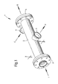
- FIG. 1 shows a water filtering device 1 comprising a hollow cylindrical housing 2 with a flanged inflow end 3, operatively connected to a supply channel for water to be treated (not shown). At its opposite end the housing 2 is provided with a flanged outflow end 4 for the discharge of retentate. About halfway the inflow end 3 and the outflow end 4, the housing 2 comprises a first lateral branch 5 operatively connected to a discharge channel for the discharge of treated water (not shown). Near the outflow end 4 the housing 2 comprises a second lateral branch 6 extending in a direction opposite to the direction of the first branch 5.
- a monolith membrane 10 is encased within the housing 2, as shown in Figure 2 .
- the membrane 10 comprises a cylindrical periphery 11 surrounding a grid of parallel channels 12 extending in a direction parallel to the longitudinal direction of the cylindrical housing 2.
- multi-channel membranes can be used, e.g., with an array of channels with circular cross sections and/or wedge shaped cross sections or with any other suitable cross section.
- the inner walls of the channels 12 are provided with a photocatalyic coating 13 of anatase or any other suitable photocatalytic material or composition.
- an optical fibre 14 is provided running from the inflow end 3 to the outflow end 4 of the membrane 10. All fibres 14 are operatively connected to a UV light source (not shown).
- annular permeate collection channel 15 which is in open connection with the lateral branches 5, 6 of the cylindrical housing 2.
- the second lateral branch 6 is closed off and water is supplied to the device 1 via the inflow end 3 of the cylindrical housing 2 in the direction of arrow I in Figure 1 .
- the inflow end 3 is in open connection with the channels 12 of the membrane, but is sealed from the annular permeate collection channel 15.
- Water is fed under pressure into the channels 12, while the photocatalytic coating 13 in the channels 12 is exposed to UV light guided through the fibers 14. Under the influence of the photocatalytic activity of the photocatalytic coating 13 contaminants in the water are decomposed. Simultaneously the water is forced to pass the channel walls and flows via the channel walls to the outer periphery 11 where it enters the annular permeate collection channel 15. Subsequently, the filtered water is discharged via the lateral branch 5 in the direction indicated in Figure 1 by arrow P.
- a concentrate of contaminants is retained in the channels 12 as a retentate and is subsequently discharged via the outflow end 4 in the direction indicated in Figure 1 by arrow R.
- the inflow end 3 and the first lateral branch 5 are closed off and the second lateral branch 6 is opened and connected to a supply of cleaning water of a high purity (not shown) or of any other suitable cleaning liquid or gas.
- the cleaning medium is forced in the direction indicated in Figure 1 by arrow C to enter the membrane 10 via the outer periphery 11 through the channel walls into the channels 12. Contaminants retained in the membrane material or in the photocatalytic coating layer are flushed away and discharged via the outflow end 4.
Landscapes
- Life Sciences & Earth Sciences (AREA)
- Hydrology & Water Resources (AREA)
- Engineering & Computer Science (AREA)
- Environmental & Geological Engineering (AREA)
- Water Supply & Treatment (AREA)
- Chemical & Material Sciences (AREA)
- Organic Chemistry (AREA)
- Health & Medical Sciences (AREA)
- Toxicology (AREA)
- Catalysts (AREA)
- Physical Water Treatments (AREA)
Abstract
A device and process for treatment of water by filtration using a photocatalytic membrane, wherein light is guided from a light source to the membrane via a optical fibre. The device comprises a housing encasing one or more membranes in a permeate collection channel. The membranes comprise channels between a supply for untreated water and a discharge for retentate. The channels are provided with photocatalytic walls within a light exposure scope of one or more optical fibres connected to a light source.
Description
- The present invention relates to a device and a process for treatment of water, in particular purification of water, such as municipal waste water or waste water from oil recovery, mining or industrial processes.
- Membrane filtration can be used to remove contaminations from water. Depending on the pore size of the membrane, distinction is made between microfiltration (for the removal of, e.g., bacteria), ultrafiltration (suitable for removing colloids and viruses), nanofiltration (suitable for removing colorants, inorganic contaminants, pesticides, etc.) and reverse osmosis (suitable for desalination of salt water). Due to the effect of biofouling such membranes need to be cleaned on a regular base and have limited purification efficiency.
- It is an object of the invention to provide a device and a process for water treatment with improved purification efficiency, particularly for organic contaminants. It is a further object to provide a device requiring less maintenance time and effort for the removal of biofouling.
- The object of the invention is achieved with a device for water treatment comprising a housing encasing one or more membranes and a permeate collection channel at least partly surrounding the one or more membranes, wherein the membranes comprise one or more channels between a supply for untreated water and a discharge for retentate, wherein at least a part of the channels is provided with photocatalytic channel walls within a light exposure scope of one or more optical fibres connected to a light source. The one or more optical fibres are for instance positioned within at least a part of the channels. Combining membrane filtration with photocatalytic breakdown of contaminants does not only improve the degree of purification but also reduces biofouling. Water is transported through the channels, typically under pressure. Most of the water is pressed through the pores of the membrane in a direction perpendicular to the flow direction within the channel. A concentrate of contaminants remains in the channel as a retentate and is discharged via the channel. Purified water exits the membrane at its outer peripheral surface.
- The membrane can for instance be a monolith membrane or a multichannel membrane. Such membranes comprise a plurality of channels and have a high area-to-volume ratio and, consequently, a higher filtration capacity.
- The channels can have a constant diameter or varying diameters, e.g., the diameters of the channels may gradually decrease from the in flow opening to the out flow opening or the other way around. Optionally, the channel diameters may gradually increase or decrease as a function of the distance to the distance to the outer periphery. The channels may have a square, rectangular, wedge-shaped or circular cross sectional shape or any other suitable shape. The average width of the channels may for instance be between 0.5 - 5 mm. Smaller or larger channels can also be used if so desired. The cross sectional channel density of the membrane can for instance be 2 - 4 channels per cm2.
- The membrane can for instance have an area-to-volume ratio of about 30 to about 800 m2/m3, e.g., of about 150 to 750 m2/m3.
- The membrane can for instance be a micro-filtration membrane. In such case the pore size is typically between 100 - 1000 nm, at least at the channel walls. Preferably, the membrane is an ultra filtration membrane with pore sizes between 10 - 100 nm at least at the channel walls. This would also remove colloids and viruses. More preferably, nano-filtration membranes are used having a pore size of 1 - 10 nm at least at the channel walls, which would even remove colorants, pesticides and oily components.
- Pore sizes at a distance from the channel wall may, e.g., be of the same size or larger than the pores at the channel wall. For instance, the membrane may have a layered structure with smaller pores at the channel wall and with a porous support structure between the channel with larger pores.
- Optionally, a plurality of membranes can be used. For instance, one or more ultra filtration membranes can be used downstream one or more microfiltration membranes. Similarly, one or more nanofiltration membranes can be used downstream one or more micro- and/or ultrafiltration membranes.
- Alternatively, or additionally, the membrane may be a membrane module including a bundle of hollow fibre membranes. In such case, water to be treated can be supplied via the fibres and be filtered when leaving the fibre via the fibre wall (inside-out filtration). In that case, at last the inner wall of the hollow fibre membranes should be photocatalytic. Alternatively, water to be treated can be supplied to the space between the bundled fibres and be filtered when entering the fibres via their respective walls (outside-in filtration). In that case, at least the outer walls of the hollow fibre membranes should be photocatalytic. Optionally, hollow fibre membranes can be used which can also perform as optical fibres, such as silica glass membrane fibres.
- The membrane can be a ceramic membrane, e.g., of alumina, titania, zirconia, silica, silicon carbide or mixtures thereof. Optionally, the membranes can be laminated membranes comprising a plurality of layers of the same or different pore size made of, e.g., alumina - such as alpha alumina and/or gamma alumina - titania, zirconia, silica, silicon carbide or mixtures thereof.
- Polymeric membranes can also be used, particularly membranes of polymers which are resistant to the photocatalytic activity. Suitable polymers include cellulose acetate, cellulose nitrate, polyacrylonitrile, polyamide, polyethersulfone, polyimide, polysulfone, polyvinyl alcohol, polyvinylidene fluoride or mixtures and/or hybrids thereof.
- The membrane material can be photocatalytic, for instance if it comprises anatase and/or brooktite titanium dioxide. In such case, the membrane material may for instance comprise at least 80 wt.%, e.g., at least 90 wt.% or at least 95 wt.% of anatase, brooktite or nano-TiO2. Lower contents can also be used if so desired. Optionally, the membrane material can be spiked, e.g., with nitrogen ions or doped, e.g., with one or more metal oxides like tungsten trioxide, anatase or brooktite nanoparticles and/or Ti02 nanotubes or nanoribbons.
- Alternatively, or additionally, the channel walls may be coated with a photocatalytic coating, e.g., comprising anatase and/or brooktite titanium dioxide and/or Ti02 nanotubes, nanoribbons and/or nanoparticles. In such case, the coating material may for instance comprise at least 80 wt.%, e.g., at least 90 wt.% or at least 95 wt.% of anatase, brooktite or nano-TiO2. Lower contents can also be used if so desired. A commercially available example of a suitable Ti02 photocatalyst is Hombikat® UV100, ex. Sachtleben AG, Germany.
- Coating can for instance be carried out by wash coating or dip coating. Other suitable application methods include for instance spraying or vapour deposition techniques.
- The layer thickness of the photocatalytic coating can for instance be about 1 - 9 micrometer, e.g., about 2 - 4 micrometer. Thicker or thinner layers can also be used, if so desired.
- Optionally, the membrane material and/or the photocatalytic coating can comprise additives, such as activated carbon, zeolites, activated alumina and/or carbon nanotubes.
- The light can for instance be UV light, more particularly UV light having a wave length maximizing the photocatalytic activity of the used material. If the photocatalytic material is based on anatase, particularly suitable wave lengths are below 500 nm, e.g., below 400 nm. Particularly suitable are wavelengths in the range of 275 - 388 nm.
- Suitable UV light sources are for instance mercury short arc lamps, xenon lamps or LED's. Other UV-emitting lamp types can also be used, alone or in combination.
- The optical fibre conducts light from a light source irradiating the photocatalytic channel walls. The light source may be positioned outside the channel. One light source can be used to supply light via a plurality of optical fibres into a large number of channels.
- Suitable optical fibres are for instance made of a glass, such as silica glasses, chalcogenide glasses, phosphate glasses or fluoride glasses, such as fluorozirconate or fluoroaluminate glasses. Alternatively, the fibres can comprise crystalline materials like sapphire, or Plastic Optical Fibre (POF), for instance of poly(methyl methacrylate) (PMMA) or perfluorinated polymers, such as polyperfluorobutenylvinylether.
- The fibre material can for instance be doped, e.g., with germanium dioxide (Ge02), aluminium oxide (Al203), fluorine, boron trioxide (B2O3) or rare earth materials.
- Optical fibres are typically provided with a cladding of a lower refractive index in order to prevent radial light emission. However, for the present invention, radial light emission is desired, so preferably optical fibres are used without such a cladding. Optionally, the fibres can comprise a cladding with a gradually decreasing thickness, to optimize light distribution over the length of the fibres.
- To improve side light emission by the optical fibres the ends of the fibres may be coated with a reflective material, such as aluminium or an aluminium alloy.
- The fibres can for since be bundles of smaller fibres, e.g., of about 80 to about 120 fibres.
- The fibres can heave any suitable diameter, e.g., a diameter of about 0,4 - 0.6 mm.
- The membrane can for instance be encased in a housing, e.g., a cylinder, defining a discharge channel for filtered water. The housing will typically have an inlet connecting the inlet side of the membrane to a supply of water to be treated, and an outlet at an opposite end for the discharge of retentate. Further, it will typically have one or more discharge channels, e.g., at a side face, for the discharge of treated water. Optionally, it can also be provided with a supply connection for the supply of fresh water or a cleaning liquid for cleaning the membrane by a reverse flow.
- Water to be treated can for instance be passed through the channels in the membrane under a pressure of 0,5 bar or higher, e.g., at least 5 bar or at least 10 bar. Lower pressures can also be used if so desired. The water can for instance be passed through the channels in the membrane under a pressure of 60 bar or lower, e.g., at most 40 bar or at most 20 bar. Higher pressures can also be used if so desired. Any one of these upper limits can be combined with any one of the afore mentioned lower limits to form a suitable pressure range.
- The disclosed device is particularly suitable for removing organic hydrocarbon contaminations.
- The invention will be further described under reference to the accompanying drawings. In the drawings:
-
Figure 1 : shows an exemplary embodiment of a device according to the present invention; -
Figure 2 : shows the device ofFigure 1 in cross section. -
Figure 1 shows a water filtering device 1 comprising a hollowcylindrical housing 2 with a flanged inflow end 3, operatively connected to a supply channel for water to be treated (not shown). At its opposite end thehousing 2 is provided with a flanged outflow end 4 for the discharge of retentate. About halfway the inflow end 3 and the outflow end 4, thehousing 2 comprises a firstlateral branch 5 operatively connected to a discharge channel for the discharge of treated water (not shown). Near the outflow end 4 thehousing 2 comprises a second lateral branch 6 extending in a direction opposite to the direction of thefirst branch 5. - A
monolith membrane 10 is encased within thehousing 2, as shown inFigure 2 . Themembrane 10 comprises acylindrical periphery 11 surrounding a grid ofparallel channels 12 extending in a direction parallel to the longitudinal direction of thecylindrical housing 2. In other suitable embodiments, multi-channel membranes can be used, e.g., with an array of channels with circular cross sections and/or wedge shaped cross sections or with any other suitable cross section. - The inner walls of the
channels 12 are provided with aphotocatalyic coating 13 of anatase or any other suitable photocatalytic material or composition. - In each of the
channels 12 anoptical fibre 14 is provided running from the inflow end 3 to the outflow end 4 of themembrane 10. Allfibres 14 are operatively connected to a UV light source (not shown). - Between the
outer periphery 11 of themembrane 10 and the inner wall of thecylindrical housing 2 remains an annularpermeate collection channel 15 which is in open connection with thelateral branches 5, 6 of thecylindrical housing 2. - During operation of the device 1, the second lateral branch 6 is closed off and water is supplied to the device 1 via the inflow end 3 of the
cylindrical housing 2 in the direction of arrow I inFigure 1 . The inflow end 3 is in open connection with thechannels 12 of the membrane, but is sealed from the annularpermeate collection channel 15. Water is fed under pressure into thechannels 12, while thephotocatalytic coating 13 in thechannels 12 is exposed to UV light guided through thefibers 14. Under the influence of the photocatalytic activity of thephotocatalytic coating 13 contaminants in the water are decomposed. Simultaneously the water is forced to pass the channel walls and flows via the channel walls to theouter periphery 11 where it enters the annularpermeate collection channel 15. Subsequently, the filtered water is discharged via thelateral branch 5 in the direction indicated inFigure 1 by arrow P. - A concentrate of contaminants is retained in the
channels 12 as a retentate and is subsequently discharged via the outflow end 4 in the direction indicated inFigure 1 by arrow R. - When the device 1 needs to be cleaned the inflow end 3 and the first
lateral branch 5 are closed off and the second lateral branch 6 is opened and connected to a supply of cleaning water of a high purity (not shown) or of any other suitable cleaning liquid or gas. The cleaning medium is forced in the direction indicated inFigure 1 by arrow C to enter themembrane 10 via theouter periphery 11 through the channel walls into thechannels 12. Contaminants retained in the membrane material or in the photocatalytic coating layer are flushed away and discharged via the outflow end 4.
Claims (10)
- A device for water treatment comprising a housing encasing one or more membranes and a permeate collection channel at least partly surrounding the one or more membranes, wherein the membranes comprise one or more channels between a supply for untreated water and a discharge for retentate, wherein at least a part of the channels is provided with photocatalytic channel walls within a light exposure scope of one or more optical fibres connected to a light source.
- A device according to claim 1 wherein the membrane is a submicron filtration membrane.
- A device according to claim 2 wherein the membrane is an ultrafiltration membrane.
- A device according to any one of the preceding claims wherein the walls of the channel are coated with a photocatalytic material comprises anatase and/or brooktite titanium dioxide.
- A device according to any one of the preceding claims wherein the membrane is at least partly made of a photocatalytic material.
- A device according to any one of the preceding claims wherein the light source is a UV light source.
- A device according to anyone of the preceding claims wherein at least a part of the optical conductors are glass fibres.
- A device according to any one of the preceding claims wherein the membrane is a monolithic membrane, a multi-channel membrane or a bundle of hollow fibre membranes.
- A device according to any one of the preceding claims wherein the membrane has an area to volume ratio of 30 - 800 m2/m3, e.g., of 150 - 750 m2/m3.
- A process for treatment of water by filtration using a photocatalytic membrane, wherein light is guided from a light source to the membrane via a optical fibre.
Priority Applications (1)
| Application Number | Priority Date | Filing Date | Title |
|---|---|---|---|
| EP11175401A EP2551241A1 (en) | 2011-07-26 | 2011-07-26 | Water treatment device and process |
Applications Claiming Priority (1)
| Application Number | Priority Date | Filing Date | Title |
|---|---|---|---|
| EP11175401A EP2551241A1 (en) | 2011-07-26 | 2011-07-26 | Water treatment device and process |
Publications (1)
| Publication Number | Publication Date |
|---|---|
| EP2551241A1 true EP2551241A1 (en) | 2013-01-30 |
Family
ID=45381290
Family Applications (1)
| Application Number | Title | Priority Date | Filing Date |
|---|---|---|---|
| EP11175401A Withdrawn EP2551241A1 (en) | 2011-07-26 | 2011-07-26 | Water treatment device and process |
Country Status (1)
| Country | Link |
|---|---|
| EP (1) | EP2551241A1 (en) |
Cited By (1)
| Publication number | Priority date | Publication date | Assignee | Title |
|---|---|---|---|---|
| DE102015008396A1 (en) * | 2015-06-30 | 2017-01-05 | Mann + Hummel Gmbh | Membrane device and module of a membrane filter device |
Citations (1)
| Publication number | Priority date | Publication date | Assignee | Title |
|---|---|---|---|---|
| JP2001232380A (en) * | 2000-02-21 | 2001-08-28 | Hitachi Plant Eng & Constr Co Ltd | Water treatment method |
-
2011
- 2011-07-26 EP EP11175401A patent/EP2551241A1/en not_active Withdrawn
Patent Citations (1)
| Publication number | Priority date | Publication date | Assignee | Title |
|---|---|---|---|---|
| JP2001232380A (en) * | 2000-02-21 | 2001-08-28 | Hitachi Plant Eng & Constr Co Ltd | Water treatment method |
Cited By (2)
| Publication number | Priority date | Publication date | Assignee | Title |
|---|---|---|---|---|
| DE102015008396A1 (en) * | 2015-06-30 | 2017-01-05 | Mann + Hummel Gmbh | Membrane device and module of a membrane filter device |
| DE102015008396B4 (en) | 2015-06-30 | 2019-12-05 | Mann+Hummel Gmbh | Light pipe module and membrane filter device with such |
Similar Documents
| Publication | Publication Date | Title |
|---|---|---|
| Cui et al. | Preparation and application of zeolite/ceramic microfiltration membranes for treatment of oil contaminated water | |
| JP4447457B2 (en) | Filtration equipment, membrane bioreactors, and membrane bioreactor processes | |
| KR101513250B1 (en) | Central baffle, pressurized hollow fiber membrane module having the same and cleaning method thereof | |
| US20150060360A1 (en) | Systems and methods of membrane separation | |
| CN105073228B (en) | Integrated ultrafiltration and reverse osmosis desalinization system | |
| KR100876347B1 (en) | Membrane Modules and Water Treatment Systems | |
| GB2583566A (en) | Method and apparatus for treating commercial and industrial laundry wastewater | |
| KR101908704B1 (en) | Membrane Module using Hallow Fiber | |
| RU2004136167A (en) | FILTERING DEVICE AS A HOLLOW FIBER MEMBRANE AND ITS APPLICATION FOR CLEANING WASTE WATER, AS WELL AS A MEMBRANE BIOREACTOR | |
| JP4225471B2 (en) | Operation method of multistage separation membrane module | |
| JP5795459B2 (en) | Hollow fiber membrane for immersion filtration, hollow fiber membrane module for immersion filtration using the same, immersion filtration device, and immersion filtration method | |
| CA2384095A1 (en) | Water treatment systems and methods | |
| US10576425B2 (en) | Unhoused filtration device and methods of use | |
| CN212174708U (en) | Low-pressure nanofiltration water purification membrane | |
| KR101402399B1 (en) | Lower water collecting assembly of pressured membrane module water-purifying apparatus | |
| US20190300396A1 (en) | Method and apparatus for improved filtration by a ceramic membrane | |
| CN102718282B (en) | Optical fiber type ultrafiltration membrane loaded with quantum dot modified titanium dioxide | |
| KR101557544B1 (en) | Hollow fiber membrane module | |
| CN210544407U (en) | Internal pressure type ultrafiltration membrane separation water purification system | |
| CN210419587U (en) | Photocatalysis-nanofiltration ceramic membrane advanced water purification treatment device | |
| JP2012061419A (en) | Water separation membrane module | |
| KR101373938B1 (en) | High-flux pressured membrane module water-purifying apparatus | |
| Choi et al. | Energy management in submerged microfiltration systems by optimum control of aeration | |
| Pastrana-Martínez et al. | Photocatalytic membranes: Synthesis, properties, and applications | |
| Radcliff et al. | Application of membrane technology to the production of drinking water |
Legal Events
| Date | Code | Title | Description |
|---|---|---|---|
| PUAI | Public reference made under article 153(3) epc to a published international application that has entered the european phase |
Free format text: ORIGINAL CODE: 0009012 |
|
| AK | Designated contracting states |
Kind code of ref document: A1 Designated state(s): AL AT BE BG CH CY CZ DE DK EE ES FI FR GB GR HR HU IE IS IT LI LT LU LV MC MK MT NL NO PL PT RO RS SE SI SK SM TR |
|
| AX | Request for extension of the european patent |
Extension state: BA ME |
|
| STAA | Information on the status of an ep patent application or granted ep patent |
Free format text: STATUS: THE APPLICATION IS DEEMED TO BE WITHDRAWN |
|
| 18D | Application deemed to be withdrawn |
Effective date: 20130731 |