EP2551142A2 - Grounding structure of high voltage secondary battery for vehicle - Google Patents
Grounding structure of high voltage secondary battery for vehicle Download PDFInfo
- Publication number
- EP2551142A2 EP2551142A2 EP12005394A EP12005394A EP2551142A2 EP 2551142 A2 EP2551142 A2 EP 2551142A2 EP 12005394 A EP12005394 A EP 12005394A EP 12005394 A EP12005394 A EP 12005394A EP 2551142 A2 EP2551142 A2 EP 2551142A2
- Authority
- EP
- European Patent Office
- Prior art keywords
- vehicle
- battery
- grounding structure
- secondary battery
- inverter
- Prior art date
- Legal status (The legal status is an assumption and is not a legal conclusion. Google has not performed a legal analysis and makes no representation as to the accuracy of the status listed.)
- Withdrawn
Links
Images


Classifications
-
- B—PERFORMING OPERATIONS; TRANSPORTING
- B60—VEHICLES IN GENERAL
- B60L—PROPULSION OF ELECTRICALLY-PROPELLED VEHICLES; SUPPLYING ELECTRIC POWER FOR AUXILIARY EQUIPMENT OF ELECTRICALLY-PROPELLED VEHICLES; ELECTRODYNAMIC BRAKE SYSTEMS FOR VEHICLES IN GENERAL; MAGNETIC SUSPENSION OR LEVITATION FOR VEHICLES; MONITORING OPERATING VARIABLES OF ELECTRICALLY-PROPELLED VEHICLES; ELECTRIC SAFETY DEVICES FOR ELECTRICALLY-PROPELLED VEHICLES
- B60L3/00—Electric devices on electrically-propelled vehicles for safety purposes; Monitoring operating variables, e.g. speed, deceleration or energy consumption
- B60L3/0023—Detecting, eliminating, remedying or compensating for drive train abnormalities, e.g. failures within the drive train
- B60L3/0046—Detecting, eliminating, remedying or compensating for drive train abnormalities, e.g. failures within the drive train relating to electric energy storage systems, e.g. batteries or capacitors
-
- B—PERFORMING OPERATIONS; TRANSPORTING
- B60—VEHICLES IN GENERAL
- B60L—PROPULSION OF ELECTRICALLY-PROPELLED VEHICLES; SUPPLYING ELECTRIC POWER FOR AUXILIARY EQUIPMENT OF ELECTRICALLY-PROPELLED VEHICLES; ELECTRODYNAMIC BRAKE SYSTEMS FOR VEHICLES IN GENERAL; MAGNETIC SUSPENSION OR LEVITATION FOR VEHICLES; MONITORING OPERATING VARIABLES OF ELECTRICALLY-PROPELLED VEHICLES; ELECTRIC SAFETY DEVICES FOR ELECTRICALLY-PROPELLED VEHICLES
- B60L3/00—Electric devices on electrically-propelled vehicles for safety purposes; Monitoring operating variables, e.g. speed, deceleration or energy consumption
- B60L3/0023—Detecting, eliminating, remedying or compensating for drive train abnormalities, e.g. failures within the drive train
- B60L3/0069—Detecting, eliminating, remedying or compensating for drive train abnormalities, e.g. failures within the drive train relating to the isolation, e.g. ground fault or leak current
-
- H—ELECTRICITY
- H01—ELECTRIC ELEMENTS
- H01M—PROCESSES OR MEANS, e.g. BATTERIES, FOR THE DIRECT CONVERSION OF CHEMICAL ENERGY INTO ELECTRICAL ENERGY
- H01M50/00—Constructional details or processes of manufacture of the non-active parts of electrochemical cells other than fuel cells, e.g. hybrid cells
- H01M50/20—Mountings; Secondary casings or frames; Racks, modules or packs; Suspension devices; Shock absorbers; Transport or carrying devices; Holders
- H01M50/204—Racks, modules or packs for multiple batteries or multiple cells
-
- H—ELECTRICITY
- H01—ELECTRIC ELEMENTS
- H01M—PROCESSES OR MEANS, e.g. BATTERIES, FOR THE DIRECT CONVERSION OF CHEMICAL ENERGY INTO ELECTRICAL ENERGY
- H01M50/00—Constructional details or processes of manufacture of the non-active parts of electrochemical cells other than fuel cells, e.g. hybrid cells
- H01M50/20—Mountings; Secondary casings or frames; Racks, modules or packs; Suspension devices; Shock absorbers; Transport or carrying devices; Holders
- H01M50/249—Mountings; Secondary casings or frames; Racks, modules or packs; Suspension devices; Shock absorbers; Transport or carrying devices; Holders specially adapted for aircraft or vehicles, e.g. cars or trains
-
- H—ELECTRICITY
- H01—ELECTRIC ELEMENTS
- H01M—PROCESSES OR MEANS, e.g. BATTERIES, FOR THE DIRECT CONVERSION OF CHEMICAL ENERGY INTO ELECTRICAL ENERGY
- H01M50/00—Constructional details or processes of manufacture of the non-active parts of electrochemical cells other than fuel cells, e.g. hybrid cells
- H01M50/20—Mountings; Secondary casings or frames; Racks, modules or packs; Suspension devices; Shock absorbers; Transport or carrying devices; Holders
- H01M50/298—Mountings; Secondary casings or frames; Racks, modules or packs; Suspension devices; Shock absorbers; Transport or carrying devices; Holders characterised by the wiring of battery packs
-
- H—ELECTRICITY
- H01—ELECTRIC ELEMENTS
- H01M—PROCESSES OR MEANS, e.g. BATTERIES, FOR THE DIRECT CONVERSION OF CHEMICAL ENERGY INTO ELECTRICAL ENERGY
- H01M50/00—Constructional details or processes of manufacture of the non-active parts of electrochemical cells other than fuel cells, e.g. hybrid cells
- H01M50/50—Current conducting connections for cells or batteries
-
- H—ELECTRICITY
- H02—GENERATION; CONVERSION OR DISTRIBUTION OF ELECTRIC POWER
- H02J—ELECTRIC POWER NETWORKS; CIRCUIT ARRANGEMENTS OR SYSTEMS FOR SUPPLYING OR DISTRIBUTING ELECTRIC POWER; SYSTEMS FOR STORING ELECTRIC ENERGY
- H02J7/00—Circuit arrangements for charging or discharging batteries or for supplying loads from batteries
- H02J7/70—Circuit arrangements for charging or discharging batteries or for supplying loads from batteries characterised by the mechanical construction
- H02J7/751—Circuit arrangements for charging or discharging batteries or for supplying loads from batteries characterised by the mechanical construction concerning the insertion or the connection of the batteries
-
- Y—GENERAL TAGGING OF NEW TECHNOLOGICAL DEVELOPMENTS; GENERAL TAGGING OF CROSS-SECTIONAL TECHNOLOGIES SPANNING OVER SEVERAL SECTIONS OF THE IPC; TECHNICAL SUBJECTS COVERED BY FORMER USPC CROSS-REFERENCE ART COLLECTIONS [XRACs] AND DIGESTS
- Y02—TECHNOLOGIES OR APPLICATIONS FOR MITIGATION OR ADAPTATION AGAINST CLIMATE CHANGE
- Y02E—REDUCTION OF GREENHOUSE GAS [GHG] EMISSIONS, RELATED TO ENERGY GENERATION, TRANSMISSION OR DISTRIBUTION
- Y02E60/00—Enabling technologies; Technologies with a potential or indirect contribution to GHG emissions mitigation
- Y02E60/10—Energy storage using batteries
-
- Y—GENERAL TAGGING OF NEW TECHNOLOGICAL DEVELOPMENTS; GENERAL TAGGING OF CROSS-SECTIONAL TECHNOLOGIES SPANNING OVER SEVERAL SECTIONS OF THE IPC; TECHNICAL SUBJECTS COVERED BY FORMER USPC CROSS-REFERENCE ART COLLECTIONS [XRACs] AND DIGESTS
- Y02—TECHNOLOGIES OR APPLICATIONS FOR MITIGATION OR ADAPTATION AGAINST CLIMATE CHANGE
- Y02T—CLIMATE CHANGE MITIGATION TECHNOLOGIES RELATED TO TRANSPORTATION
- Y02T90/00—Enabling technologies or technologies with a potential or indirect contribution to GHG emissions mitigation
- Y02T90/10—Technologies relating to charging of electric vehicles
- Y02T90/14—Plug-in electric vehicles
Definitions
- the following disclosure relates to a grounding structure of a high voltage secondary battery for a vehicle, and more particularly, to the grounding structure of a high voltage secondary battery for a vehicle capable of securing a stable ground potential of various electric devices of the vehicle and reducing a risk factor that may be generated due to a potential difference.
- a secondary battery capable of being charged and discharged unlike a primary battery has been actively conducted in accordance with the development of state-of-the-art fields such as a digital camera, a cellular phone, a laptop computer, a hybrid vehicle, and the like.
- An example of the secondary battery includes a nickel-cadmium battery, a nickel-metal hydride battery, a nickel-hydrogen battery, and a lithium secondary battery.
- the lithium secondary battery which has an operating voltage of 3.6 V or more, is used as a power supply of a portable electronic device or a plurality of lithium secondary batteries are connected in series with each other to thereby be used for a high output hybrid vehicle. Since this lithium secondary battery has an operating voltage three times higher than that of the nickel-cadmium battery or the nickel-metal hydride battery and is more excellent in view of energy density characteristics per unit weight than the nickel-cadmium battery or the nickel-metal hydride battery, the use of the lithium secondary battery has rapidly increased.
- the hybrid vehicle means a vehicle driven by efficiently combining two kinds or more of power sources with each other in a wide sense.
- the hybrid vehicle means a vehicle obtaining driving force by an engine using fuel and an electric motor driven by power of a battery.
- This hybrid vehicle is called a hybrid electric vehicle (HEV).
- the battery as described above may be applied to the next generation vehicle such as a plug-in hybrid electric vehicle (PHEV) and an electric vehicle (EV) as well as the HEV.
- PHEV plug-in hybrid electric vehicle
- EV electric vehicle
- the next generation vehicle is necessarily mounted with a high voltage battery configured of the lithium secondary battery as shown in FIG. 1 in order to provide driving power of the electric motor.
- This battery supplies required power while being repeatedly charged/discharged during driving of the vehicle.
- the high voltage battery provided in the next generation vehicle as described above has a very high voltage of about 680 V. Therefore, in the case in which the voltage of the battery is different from a potential of a vehicle body, it is difficult to maintain an electrically stable state, such that there is a risk that several problems may occur.
- Korean Patent Registration No. 10-0696673 As a method of managing a voltage of a battery pack, a battery managing system that may be used in a vehicle using electric energy has been disclosed in Korean Patent Registration No. 10-0696673 .
- a technology disclosed in Korean Patent Registration No. 10-0696673 is different from a technology of maintaining the potential of the vehicle body and the potential of the battery so as to be the same as each other.
- the present invention provides a grounding structure of a high voltage secondary battery for a vehicle as defined in claim 1.
- the dependent claims define preferred embodiments of the invention.
- An embodiment of the present invention is directed to providing a grounding structure of a high voltage secondary battery for a vehicle capable of securing stable ground potential of various electric devices included in the vehicle and reducing a risk factor that may be generated due to a potential difference by connecting a battery pack including a secondary battery and an inverter for the vehicle provided in the next generation vehicle such as a hybrid electric vehicle (HEV), an electric vehicle (EV), a plug-in hybrid electric vehicle (PHEV) to each other by a ground wire formed of an electric wire in order to allow a vehicle body and a battery pack to have equipotential.
- HEV hybrid electric vehicle
- EV electric vehicle
- PHEV plug-in hybrid electric vehicle
- a grounding structure of a high voltage secondary battery for a vehicle for grounding a secondary battery provided in a vehicle to allow the entire vehicle to have equipotential includes: a battery pack having a plurality of secondary batteries combined in series or parallel with each other and received in a battery case; and an inverter for a vehicle converting direct current (DC) voltage output from the battery pack into alternate current (AC) voltage and then outputting the converted AC voltage, wherein the battery pack and the inverter for a vehicle are connected to each other by a ground wire formed of an electric wire.
- DC direct current
- AC alternate current
- the grounding structure may further include a bolt insertion groove formed both at a predetermined region of the battery case and at a predetermined region of an outer portion of the inverter for a vehicle, such that the ground wire is wound around the bolts inserted into the bolt insertion grooves at both ends thereof to thereby be fixed.
- the grounding structure may further include a washer provided between the bolt insertion grooves formed in the battery case and the inverter for a vehicle and the bolts inserted in the bolt insertion grooves.
- the washer may be a toothed lock washer formed in a sawtooth shape.
- the ground wire may be connected at the shortest length.
- a predetermined region of the battery case fixed so that the ground wire is connected thereto may be in a state in which it is not painted by paint.
- FIG. 1 is an exploded perspective view showing a general high voltage battery.
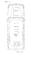
- FIG. 2 is a plan view of a vehicle in which a battery pack is mounted.
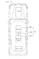
- FIG. 3 is a plan view of a hybrid vehicle to which a grounding structure of a high voltage secondary battery for a vehicle according to an exemplary embodiment of the present invention is applied.
- FIG. 4 is a front view showing the grounding structure of a high voltage secondary battery for a vehicle according to the exemplary embodiment of the present invention.
- FIG. 5 is an exploded perspective view showing a grounding structure of a high voltage secondary battery for a vehicle according to another exemplary embodiment of the present invention.
- FIG. 1 is an exploded perspective view showing a general high voltage battery
- FIG. 2 is a plan view of a vehicle in which a battery pack is mounted
- FIG. 3 is a plan view of a hybrid vehicle to which a grounding structure of a high voltage secondary battery for a vehicle according to an exemplary embodiment of the present invention is applied
- FIG. 4 is a front view showing the grounding structure of a high voltage secondary battery for a vehicle according to the exemplary embodiment of the present invention
- FIG. 5 is an exploded perspective view showing a grounding structure of a high voltage secondary battery for a vehicle according to another exemplary embodiment of the present invention.
- the grounding structure 10 of a high voltage secondary battery for a vehicle is designed in order to ground a secondary battery 110 included in the next generation vehicle such as a hybrid electric vehicle (HEV), an electric vehicle (EV), a plug-in hybrid electric vehicle (PHEV) to allow the entire vehicle to have equipotential.
- a hybrid electric vehicle HEV
- EV electric vehicle
- PHEV plug-in hybrid electric vehicle
- the grounding structure 10 of a high voltage secondary battery for a vehicle is configured to include: a battery pack 100 having a plurality of secondary batteries 110 combined in series or parallel with each other and received in a battery case 120; and an inverter 200 for a vehicle converting direct current (DC) voltage output from the battery pack 100 into alternate current (AC) voltage and then outputting the converted AC voltage.
- a battery pack 100 having a plurality of secondary batteries 110 combined in series or parallel with each other and received in a battery case 120
- DC direct current
- AC alternate current
- the battery pack 100 and the inverter 200 for a vehicle are connected to each other by a ground wire 300 formed of an electric wire to allow the battery pack 100 and the entire vehicle to have equipotential.
- the next generation vehicle such as the HEV, the EV, the PHEV starts
- electricity is supplied to all of the electric components, such that the battery pack 100 is activated and the inverter 200 for a vehicle supplies the electricity to a motor to start the motor.
- the inverter 200 for a vehicle is used to convert DV electricity for a vehicle into AC electricity for a home at the time of using a television, a laptop computer, an audio device, or the like, in the vehicle as well as to supply the electricity to the motor.
- the battery pack 100 and the inverter 200 for a vehicle are connected to each other by the ground wire 300.
- a bolt insertion groove 410 into which a bolt 400 may be inserted is formed at a predetermined region of the battery case 120 and a bolt insertion groove 410 into which a bolt 400 may be inserted is formed at a predetermined region of an outer portion of the inverter 200 for a vehicle, such that the ground wire 300 may be wound around the bolts 400 inserted into the bolt insertion grooves 410 at both ends thereof to thereby be fixed.
- the bolt insertion grooves 410 which are formed so that the bolts 400 for fixing ground wire 300 may be inserted thereinto, are depressed and formed at the predetermined regions of the battery case 120 and the outer portion of the inverter 200 for a vehicle, but do not penetrate through the battery case 120 and the inverter 200 for a vehicle.
- the ground wire 300 which is to allow the inverter 200 for a vehicle and the battery pack 100 to have equipotential, is wound around the bolts 400 to thereby be fixed in a state in which a cover of both ends thereof is removed.
- the predetermined region of the battery case 120 fixed so that the ground wire 300 is connected thereto is in a state in which it is not painted by paint.
- the grounding structure 10 of a high voltage secondary battery for a vehicle when an end of the ground wire 300 and the battery case 120 are connected to each other, they are connected to each other after the paint is removed at a portion to be connected.
- the predetermined region of the outer portion of the inverter 200 for a vehicle connected to the ground wire 300 is in a state in which it is not painted.
- the grounding structure 10 of a high voltage secondary battery for a vehicle may further include a washer 500 provided between the bolt insertion grooves 410 formed in the battery case 120 and the inverter 200 for a vehicle and the bolts 400 inserted into the bolt insertion grooves 410 in order to improve fixability.
- the washer 500 may be a toothed lock washer 500 of which an inner surface or an outer surface is formed in a sawtooth shape as shown in FIG. 5 .
- the washer 500 has a more excellent looseness prevention effect, such that the bolts 400 and both ends of the ground wire 300 may be stably fixed.
- the ground wire 300 a general electric wire may be used as it is.
- the ground wire 300 may also be used in a state in which a terminal 310 is compressed and fixed to the ground wire 300 of which the cover of both ends is removed, such that a core wire in which current may flow is exposed.
- the terminal 310 compressed and fixed to both ends of the ground wire 300 to thereby be connected thereto may have a 'C' shape so as to enclose the bolt 400.
- the terminal 310 has an 'O' shape as shown in FIG. 5 , such that the bolt 400 may be inserted into a hollow region in the terminal to thereby be fixed together with the washer 500.
- the ground wire 300 is connected at the shortest length.
- the ground wire 300 connected between the battery pack and the inverter 200 for a vehicle is grounded at the shortest distance so as not to cause electromagnetic interference (EMI) or a problem in electromagnetic compatibility (EMC). To this end, the ground wire 300 is connected to the inverter 200 for a vehicle.
- EMI electromagnetic interference
- EMC electromagnetic compatibility
- the ground wire 300 is connected to a portion at which a distance between the battery pack 100 and the inverter 200 for a vehicle is the shortest. Further, in the case in which the ground wire 300 is fixed using the bolts 400 as described above, it is preferable that the bolt insertion grooves 410 are formed in a predetermined region of the outermost portion of the battery case 120 and a predetermined region of the outermost portion the most adjacent to the battery case 120.
- the inverter 200 for a vehicle provided in the next generation vehicle such as the HEV, the EV, and the PHEV and the battery pack 100 including the secondary batteries 110 are connected to each other by the ground wire 300 formed of the electric wire in order to allow the vehicle body and the battery pack 100 to have equipotential, thereby making it possible to secure stable ground potential of various electric devices included in the vehicle and reduce a risk factor that may be generated due to a potential difference.
- the battery pack 100 and the inverter 200 for a vehicle are connected to each other to ground, such that a smaller potential difference is generated as compared to the case in which the secondary battery is grounded through the connection of the vehicle body, thereby making it possible to improve electrical stability of the vehicle.
- the battery pack 100 and the inverter 200 for a vehicle are connected to each other at a distance as short as possible, thereby making it possible to minimize the EMI/EMC problem.
Landscapes
- Engineering & Computer Science (AREA)
- Chemical & Material Sciences (AREA)
- Chemical Kinetics & Catalysis (AREA)
- Electrochemistry (AREA)
- General Chemical & Material Sciences (AREA)
- Power Engineering (AREA)
- Sustainable Energy (AREA)
- Life Sciences & Earth Sciences (AREA)
- Sustainable Development (AREA)
- Transportation (AREA)
- Mechanical Engineering (AREA)
- Aviation & Aerospace Engineering (AREA)
- Electric Propulsion And Braking For Vehicles (AREA)
- Battery Mounting, Suspending (AREA)
- Arrangement Or Mounting Of Propulsion Units For Vehicles (AREA)
Abstract
Description
- This application claims priority under 35 U.S.C. §119 to Korean Patent Application No.
10-2011-0073688, filed on 07, 25, 2011 - The following disclosure relates to a grounding structure of a high voltage secondary battery for a vehicle, and more particularly, to the grounding structure of a high voltage secondary battery for a vehicle capable of securing a stable ground potential of various electric devices of the vehicle and reducing a risk factor that may be generated due to a potential difference.
- Generally, research into a secondary battery capable of being charged and discharged unlike a primary battery has been actively conducted in accordance with the development of state-of-the-art fields such as a digital camera, a cellular phone, a laptop computer, a hybrid vehicle, and the like. An example of the secondary battery includes a nickel-cadmium battery, a nickel-metal hydride battery, a nickel-hydrogen battery, and a lithium secondary battery.
- Among them, the lithium secondary battery, which has an operating voltage of 3.6 V or more, is used as a power supply of a portable electronic device or a plurality of lithium secondary batteries are connected in series with each other to thereby be used for a high output hybrid vehicle. Since this lithium secondary battery has an operating voltage three times higher than that of the nickel-cadmium battery or the nickel-metal hydride battery and is more excellent in view of energy density characteristics per unit weight than the nickel-cadmium battery or the nickel-metal hydride battery, the use of the lithium secondary battery has rapidly increased.
- Generally, the hybrid vehicle means a vehicle driven by efficiently combining two kinds or more of power sources with each other in a wide sense. However, in most cases, the hybrid vehicle means a vehicle obtaining driving force by an engine using fuel and an electric motor driven by power of a battery. This hybrid vehicle is called a hybrid electric vehicle (HEV).
- In addition, the battery as described above may be applied to the next generation vehicle such as a plug-in hybrid electric vehicle (PHEV) and an electric vehicle (EV) as well as the HEV.
- The next generation vehicle is necessarily mounted with a high voltage battery configured of the lithium secondary battery as shown in
FIG. 1 in order to provide driving power of the electric motor. This battery supplies required power while being repeatedly charged/discharged during driving of the vehicle. - Generally, the high voltage battery provided in the next generation vehicle as described above has a very high voltage of about 680 V. Therefore, in the case in which the voltage of the battery is different from a potential of a vehicle body, it is difficult to maintain an electrically stable state, such that there is a risk that several problems may occur.
- According to the related art, as a method of managing a voltage of a battery pack, a battery managing system that may be used in a vehicle using electric energy has been disclosed in Korean Patent Registration No.
10-0696673 10-0696673 - Therefore, in the next generation vehicle, a technology of allowing a high voltage battery and a vehicle body to have equipotential is significantly required.
- Korean Patent No.
10-0696673 - The present invention provides a grounding structure of a high voltage secondary battery for a vehicle as defined in claim 1. The dependent claims define preferred embodiments of the invention. An embodiment of the present invention is directed to providing a grounding structure of a high voltage secondary battery for a vehicle capable of securing stable ground potential of various electric devices included in the vehicle and reducing a risk factor that may be generated due to a potential difference by connecting a battery pack including a secondary battery and an inverter for the vehicle provided in the next generation vehicle such as a hybrid electric vehicle (HEV), an electric vehicle (EV), a plug-in hybrid electric vehicle (PHEV) to each other by a ground wire formed of an electric wire in order to allow a vehicle body and a battery pack to have equipotential.
- In one general aspect, a grounding structure of a high voltage secondary battery for a vehicle for grounding a secondary battery provided in a vehicle to allow the entire vehicle to have equipotential, includes: a battery pack having a plurality of secondary batteries combined in series or parallel with each other and received in a battery case; and an inverter for a vehicle converting direct current (DC) voltage output from the battery pack into alternate current (AC) voltage and then outputting the converted AC voltage, wherein the battery pack and the inverter for a vehicle are connected to each other by a ground wire formed of an electric wire.
- The grounding structure may further include a bolt insertion groove formed both at a predetermined region of the battery case and at a predetermined region of an outer portion of the inverter for a vehicle, such that the ground wire is wound around the bolts inserted into the bolt insertion grooves at both ends thereof to thereby be fixed.
- The grounding structure may further include a washer provided between the bolt insertion grooves formed in the battery case and the inverter for a vehicle and the bolts inserted in the bolt insertion grooves.
- The washer may be a toothed lock washer formed in a sawtooth shape.
- The ground wire may be connected at the shortest length.
- A predetermined region of the battery case fixed so that the ground wire is connected thereto may be in a state in which it is not painted by paint.
-
FIG. 1 is an exploded perspective view showing a general high voltage battery. -
FIG. 2 is a plan view of a vehicle in which a battery pack is mounted. -
FIG. 3 is a plan view of a hybrid vehicle to which a grounding structure of a high voltage secondary battery for a vehicle according to an exemplary embodiment of the present invention is applied. -
FIG. 4 is a front view showing the grounding structure of a high voltage secondary battery for a vehicle according to the exemplary embodiment of the present invention. -
FIG. 5 is an exploded perspective view showing a grounding structure of a high voltage secondary battery for a vehicle according to another exemplary embodiment of the present invention. -
10: grounding structure of high voltage secondary battery 100: battery pack 110: secondary battery 120: battery case 200: inverter for vehicle 300: ground wire 310: terminal 400: bolt 410: bolt insertion groove 500: washer - Hereinafter, a grounding structure of a high voltage secondary battery for a vehicle according to an exemplary embodiment of the present invention having the above-mentioned characteristics will be described in more detail with reference to the accompanying drawings.
-
FIG. 1 is an exploded perspective view showing a general high voltage battery;FIG. 2 is a plan view of a vehicle in which a battery pack is mounted;FIG. 3 is a plan view of a hybrid vehicle to which a grounding structure of a high voltage secondary battery for a vehicle according to an exemplary embodiment of the present invention is applied;FIG. 4 is a front view showing the grounding structure of a high voltage secondary battery for a vehicle according to the exemplary embodiment of the present invention; andFIG. 5 is an exploded perspective view showing a grounding structure of a high voltage secondary battery for a vehicle according to another exemplary embodiment of the present invention. - The
grounding structure 10 of a high voltage secondary battery for a vehicle according to the exemplary embodiment of the present invention is designed in order to ground asecondary battery 110 included in the next generation vehicle such as a hybrid electric vehicle (HEV), an electric vehicle (EV), a plug-in hybrid electric vehicle (PHEV) to allow the entire vehicle to have equipotential. - The
grounding structure 10 of a high voltage secondary battery for a vehicle according to the exemplary embodiment of the present invention is configured to include: abattery pack 100 having a plurality ofsecondary batteries 110 combined in series or parallel with each other and received in abattery case 120; and aninverter 200 for a vehicle converting direct current (DC) voltage output from thebattery pack 100 into alternate current (AC) voltage and then outputting the converted AC voltage. - In the
grounding structure 10 of a high voltage secondary battery for a vehicle according to the exemplary embodiment of the present invention, thebattery pack 100 and theinverter 200 for a vehicle are connected to each other by aground wire 300 formed of an electric wire to allow thebattery pack 100 and the entire vehicle to have equipotential. - Generally, when the next generation vehicle such as the HEV, the EV, the PHEV starts, electricity is supplied to all of the electric components, such that the
battery pack 100 is activated and theinverter 200 for a vehicle supplies the electricity to a motor to start the motor. - The
inverter 200 for a vehicle is used to convert DV electricity for a vehicle into AC electricity for a home at the time of using a television, a laptop computer, an audio device, or the like, in the vehicle as well as to supply the electricity to the motor. - As shown in
FIGS. 3 and4 , in thegrounding structure 10 of a high voltage secondary battery for a vehicle according to the exemplary embodiment of the present invention, thebattery pack 100 and theinverter 200 for a vehicle are connected to each other by theground wire 300. In this configuration, abolt insertion groove 410 into which abolt 400 may be inserted is formed at a predetermined region of thebattery case 120 and abolt insertion groove 410 into which abolt 400 may be inserted is formed at a predetermined region of an outer portion of theinverter 200 for a vehicle, such that theground wire 300 may be wound around thebolts 400 inserted into thebolt insertion grooves 410 at both ends thereof to thereby be fixed. - The
bolt insertion grooves 410, which are formed so that thebolts 400 for fixingground wire 300 may be inserted thereinto, are depressed and formed at the predetermined regions of thebattery case 120 and the outer portion of theinverter 200 for a vehicle, but do not penetrate through thebattery case 120 and theinverter 200 for a vehicle. - The
ground wire 300, which is to allow theinverter 200 for a vehicle and thebattery pack 100 to have equipotential, is wound around thebolts 400 to thereby be fixed in a state in which a cover of both ends thereof is removed. - Further, in the
grounding structure 10 of a high voltage secondary battery for a vehicle according to the exemplary embodiment of the present invention, it is preferable that the predetermined region of thebattery case 120 fixed so that theground wire 300 is connected thereto is in a state in which it is not painted by paint. - Therefore, in the
grounding structure 10 of a high voltage secondary battery for a vehicle according to the exemplary embodiment of the present invention, when an end of theground wire 300 and thebattery case 120 are connected to each other, they are connected to each other after the paint is removed at a portion to be connected. Likewise, it is preferable that the predetermined region of the outer portion of theinverter 200 for a vehicle connected to theground wire 300 is in a state in which it is not painted. - As shown in
FIG. 4 , thegrounding structure 10 of a high voltage secondary battery for a vehicle according to the exemplary embodiment of the present invention may further include awasher 500 provided between thebolt insertion grooves 410 formed in thebattery case 120 and theinverter 200 for a vehicle and thebolts 400 inserted into thebolt insertion grooves 410 in order to improve fixability. - Particularly, the
washer 500 may be atoothed lock washer 500 of which an inner surface or an outer surface is formed in a sawtooth shape as shown inFIG. 5 . In this case, thewasher 500 has a more excellent looseness prevention effect, such that thebolts 400 and both ends of theground wire 300 may be stably fixed. - Meanwhile, as the
ground wire 300, a general electric wire may be used as it is. However, theground wire 300 may also be used in a state in which aterminal 310 is compressed and fixed to theground wire 300 of which the cover of both ends is removed, such that a core wire in which current may flow is exposed. - Here, the
terminal 310 compressed and fixed to both ends of theground wire 300 to thereby be connected thereto may have a 'C' shape so as to enclose thebolt 400. Alternatively, theterminal 310 has an 'O' shape as shown inFIG. 5 , such that thebolt 400 may be inserted into a hollow region in the terminal to thereby be fixed together with thewasher 500. - Meanwhile, in the
grounding structure 10 of a high voltage secondary battery for a vehicle according to the exemplary embodiment of the present invention, it is preferable that theground wire 300 is connected at the shortest length. - As shown in
FIG. 3 , it is preferable that theground wire 300 connected between the battery pack and theinverter 200 for a vehicle is grounded at the shortest distance so as not to cause electromagnetic interference (EMI) or a problem in electromagnetic compatibility (EMC). To this end, theground wire 300 is connected to theinverter 200 for a vehicle. - Therefore, in the
grounding structure 10 of a high voltage secondary battery for a vehicle according to the exemplary embodiment of the present invention, it is preferable that theground wire 300 is connected to a portion at which a distance between thebattery pack 100 and theinverter 200 for a vehicle is the shortest. Further, in the case in which theground wire 300 is fixed using thebolts 400 as described above, it is preferable that thebolt insertion grooves 410 are formed in a predetermined region of the outermost portion of thebattery case 120 and a predetermined region of the outermost portion the most adjacent to thebattery case 120. - As set forth above, with the
grounding structure 10 of a high voltage secondary battery for a vehicle according to the exemplary embodiment of the present invention, theinverter 200 for a vehicle provided in the next generation vehicle such as the HEV, the EV, and the PHEV and thebattery pack 100 including thesecondary batteries 110 are connected to each other by theground wire 300 formed of the electric wire in order to allow the vehicle body and thebattery pack 100 to have equipotential, thereby making it possible to secure stable ground potential of various electric devices included in the vehicle and reduce a risk factor that may be generated due to a potential difference. - In addition, with the
grounding structure 10 of a high voltage secondary battery for a vehicle according to the exemplary embodiment of the present invention, thebattery pack 100 and theinverter 200 for a vehicle are connected to each other to ground, such that a smaller potential difference is generated as compared to the case in which the secondary battery is grounded through the connection of the vehicle body, thereby making it possible to improve electrical stability of the vehicle. - Further, with the
grounding structure 10 of a high voltage secondary battery for a vehicle according to the exemplary embodiment of the present invention, thebattery pack 100 and theinverter 200 for a vehicle are connected to each other at a distance as short as possible, thereby making it possible to minimize the EMI/EMC problem. - The present invention is not limited to the above-mentioned exemplary embodiments but may be variously applied, and may be variously modified by those skilled in the art to which the present invention pertains without departing from the gist of the present invention claimed in the claims.
Claims (6)
- A grounding structure of a high voltage secondary battery (10) for a vehicle for grounding a secondary battery provided in a vehicle to allow the entire vehicle to have equipotential, the grounding structure comprising:a battery pack (100) having a plurality of secondary batteries (110) combined in series or parallel with each other and received in a battery case (120); andan inverter (200) for a vehicle converting direct current (DC) voltage output from the battery pack (100) into alternate current (AC) voltage and then outputting the converted AC voltage,wherein the battery pack (100) and the inverter (200) for a vehicle are connected to each other by a ground wire (300) formed of an electric wire.
- The grounding structure (10) of claim 1, further comprising a bolt insertion groove (410) formed both at a predetermined region of the battery case (120) and at a predetermined region of an outer portion of the inverter for a vehicle (200) and having a bolt (400) inserted thereinto, such that the ground wire (300) is wound around the bolts (400) inserted into the bolt insertion grooves (410) at both ends thereof to thereby be fixed.
- The grounding structure (10) of claim 2, further comprising a washer (500) provided between the bolt insertion grooves (410) formed in the battery case (120) and the inverter for a vehicle (200) and the bolts (400) inserted in the bolt insertion grooves (410).
- The grounding structure (10) of claim 3, wherein the washer (500) is a toothed lock washer formed in a sawtooth shape.
- The grounding structure (10) of any one of claims 1 to 4, wherein the ground wire (300) is connected at the shortest length.
- The grounding structure (10) of any one of claims 1 to 5, wherein a predetermined region of the battery case (120) fixed so that the ground wire (300) is connected thereto is in a state in which it is not painted by paint.
Applications Claiming Priority (1)
| Application Number | Priority Date | Filing Date | Title |
|---|---|---|---|
| KR1020110073688A KR20130012459A (en) | 2011-07-25 | 2011-07-25 | Earth apparatus for vehicle high voltage secondary battery |
Publications (2)
| Publication Number | Publication Date |
|---|---|
| EP2551142A2 true EP2551142A2 (en) | 2013-01-30 |
| EP2551142A3 EP2551142A3 (en) | 2016-03-09 |
Family
ID=46601672
Family Applications (1)
| Application Number | Title | Priority Date | Filing Date |
|---|---|---|---|
| EP12005394.7A Withdrawn EP2551142A3 (en) | 2011-07-25 | 2012-07-24 | Grounding structure of high voltage secondary battery for vehicle |
Country Status (4)
| Country | Link |
|---|---|
| US (1) | US8854832B2 (en) |
| EP (1) | EP2551142A3 (en) |
| JP (1) | JP2013023219A (en) |
| KR (1) | KR20130012459A (en) |
Cited By (2)
| Publication number | Priority date | Publication date | Assignee | Title |
|---|---|---|---|---|
| CN103723022A (en) * | 2014-01-08 | 2014-04-16 | 安徽江淮汽车股份有限公司 | High-voltage compartment structure for battery of electric vehicle |
| CN115179744A (en) * | 2022-07-13 | 2022-10-14 | 东风汽车集团股份有限公司 | Vehicle with a steering wheel |
Families Citing this family (6)
| Publication number | Priority date | Publication date | Assignee | Title |
|---|---|---|---|---|
| KR102159132B1 (en) * | 2015-05-28 | 2020-09-24 | 엘에스엠트론 주식회사 | Ultra Capacitor Module Having Voltage Balancing Apparatus |
| DE102016107038A1 (en) | 2016-04-15 | 2017-10-19 | Johnson Controls Autobatterie Gmbh & Co. Kgaa | A method and apparatus for estimating a condition of an energy storage system of a vehicle |
| CN115207533B (en) * | 2019-07-04 | 2023-07-14 | 东风汽车集团有限公司 | An equipotential carbon fiber composite battery case and automobile |
| CN110534763B (en) * | 2019-08-02 | 2022-10-14 | 上海空间电源研究所 | Thermal battery grounding device |
| CN115107492B (en) * | 2022-07-13 | 2026-02-27 | 东风汽车集团股份有限公司 | vehicle |
| CN120300676B (en) * | 2025-06-09 | 2025-08-26 | 成都恒羽科技有限公司 | A UAV equipotential system and safe operation method |
Citations (1)
| Publication number | Priority date | Publication date | Assignee | Title |
|---|---|---|---|---|
| KR100696673B1 (en) | 2005-09-27 | 2007-03-19 | 삼성에스디아이 주식회사 | Battery management system and its driving method |
Family Cites Families (21)
| Publication number | Priority date | Publication date | Assignee | Title |
|---|---|---|---|---|
| JPS59106198A (en) * | 1982-12-09 | 1984-06-19 | 松下電器産業株式会社 | Earth connection device |
| US4929185A (en) * | 1989-04-03 | 1990-05-29 | Nrc Corporation | Printed circuit board assembly |
| JPH05205868A (en) * | 1992-01-22 | 1993-08-13 | Sanyo Electric Co Ltd | High frequency heating apparatus |
| JPH07263043A (en) * | 1994-03-18 | 1995-10-13 | Sumitomo Wiring Syst Ltd | Co-fastening structure for earth terminal |
| JP3761966B2 (en) * | 1996-04-22 | 2006-03-29 | 富士重工業株式会社 | Electric vehicle power system |
| JP3388124B2 (en) * | 1996-12-27 | 2003-03-17 | 矢崎総業株式会社 | Connection terminal mounting structure |
| JPH11180163A (en) * | 1997-12-18 | 1999-07-06 | Honda Motor Co Ltd | Electric car |
| JP2000150012A (en) * | 1998-11-13 | 2000-05-30 | Yazaki Corp | Terminal rotation prevention structure |
| JP2001177285A (en) * | 1999-12-21 | 2001-06-29 | Pacific Ind Co Ltd | Electromagnetic shielded enclosure, and manufacturing method therefor |
| JP4608155B2 (en) * | 2001-09-28 | 2011-01-05 | 中洲電機株式会社 | Electrical connection screw |
| JP4004988B2 (en) * | 2003-04-16 | 2007-11-07 | 本田技研工業株式会社 | Waterproof shield device |
| JP4363900B2 (en) | 2003-06-02 | 2009-11-11 | 本田技研工業株式会社 | Inverter device for vehicle |
| JP4224005B2 (en) * | 2004-08-04 | 2009-02-12 | 矢崎総業株式会社 | Electrical junction box ground structure |
| JP2006203995A (en) * | 2005-01-19 | 2006-08-03 | Hitachi Ltd | MOS rectifier, MOS rectifier driving method, motor generator and electric vehicle using the same |
| JP2007198995A (en) * | 2006-01-30 | 2007-08-09 | Matsushita Electric Ind Co Ltd | Ground fault resistance measurement circuit and ground fault detection circuit |
| JP5030023B2 (en) | 2008-02-08 | 2012-09-19 | トヨタ自動車株式会社 | Grounding structure for vehicles |
| JP5332660B2 (en) * | 2009-01-30 | 2013-11-06 | いすゞ自動車株式会社 | Battery box unit grounding structure |
| US8384239B2 (en) * | 2009-07-16 | 2013-02-26 | GM Global Technology Operations LLC | DC source assemblies |
| JP2011077463A (en) * | 2009-10-02 | 2011-04-14 | Hitachi Automotive Systems Ltd | Power conversion apparatus, rotary electric machine using the same, and method of manufacturing semiconductor power module |
| JP5477304B2 (en) * | 2011-01-25 | 2014-04-23 | トヨタ自動車株式会社 | Power supply system, vehicle equipped with the same, and control method of power supply system |
| AU2012239991A1 (en) * | 2011-04-08 | 2013-10-31 | Polaris Industries Inc. | Electric vehicle with range extender |
-
2011
- 2011-07-25 KR KR1020110073688A patent/KR20130012459A/en not_active Ceased
-
2012
- 2012-07-24 EP EP12005394.7A patent/EP2551142A3/en not_active Withdrawn
- 2012-07-25 US US13/557,308 patent/US8854832B2/en active Active
- 2012-07-25 JP JP2012164387A patent/JP2013023219A/en active Pending
Patent Citations (1)
| Publication number | Priority date | Publication date | Assignee | Title |
|---|---|---|---|---|
| KR100696673B1 (en) | 2005-09-27 | 2007-03-19 | 삼성에스디아이 주식회사 | Battery management system and its driving method |
Cited By (2)
| Publication number | Priority date | Publication date | Assignee | Title |
|---|---|---|---|---|
| CN103723022A (en) * | 2014-01-08 | 2014-04-16 | 安徽江淮汽车股份有限公司 | High-voltage compartment structure for battery of electric vehicle |
| CN115179744A (en) * | 2022-07-13 | 2022-10-14 | 东风汽车集团股份有限公司 | Vehicle with a steering wheel |
Also Published As
| Publication number | Publication date |
|---|---|
| KR20130012459A (en) | 2013-02-04 |
| US20130026824A1 (en) | 2013-01-31 |
| JP2013023219A (en) | 2013-02-04 |
| EP2551142A3 (en) | 2016-03-09 |
| US8854832B2 (en) | 2014-10-07 |
Similar Documents
| Publication | Publication Date | Title |
|---|---|---|
| US8854832B2 (en) | Grounding structure of high voltage secondary battery for vehicle | |
| US9362040B2 (en) | Coldplate with integrated electrical components for cooling thereof | |
| US7733039B2 (en) | Electric vehicle system for charging and supplying electrical power | |
| CN104602946B (en) | Battery system, maintenance switching units and the method for manufacturing battery system | |
| CN104412417B (en) | Battery pack | |
| US9630513B2 (en) | Portable bi-directional multiport AC/DC charging cable system | |
| CN102231542B (en) | Battery charging device for electric vehicles | |
| US9948210B2 (en) | Electric power conversion device | |
| US7012822B2 (en) | Integrated traction inverter module and DC/DC converter | |
| US7982332B2 (en) | Power device for a vehicle | |
| JP6713052B2 (en) | Battery pack and automobile including the same | |
| CN103947053A (en) | Shielding construction with integral crimping piece and wiring harness comprising such shield construction | |
| US20160134141A1 (en) | Charger for group of devices | |
| US20120161564A1 (en) | Device and Method of Recycling Energy | |
| US9627909B2 (en) | Power supply device | |
| EP3379685A1 (en) | Jump starter apparatus for recharging discharged battery of transportation means | |
| CN111971817A (en) | Battery module including connector having bidirectional coupling structure | |
| US20190351772A1 (en) | Electrified vehicle power converter assembly and power conversion method | |
| EP2557611A1 (en) | High voltage secondary battery with earth member | |
| US20140252848A1 (en) | Universal power supply system with load isolating and voltage enhance device | |
| KR20200055336A (en) | Battery pack | |
| US10958204B1 (en) | Automotive electric drive systems with interleaved variable voltage converters | |
| Leuchter | Study on the hybrid power source concept of unmanned aircraft systems | |
| EP4693346A1 (en) | Resistor unit, resistor assembly, and battery pack | |
| US12587157B2 (en) | Noise removal filter |
Legal Events
| Date | Code | Title | Description |
|---|---|---|---|
| PUAI | Public reference made under article 153(3) epc to a published international application that has entered the european phase |
Free format text: ORIGINAL CODE: 0009012 |
|
| AK | Designated contracting states |
Kind code of ref document: A2 Designated state(s): AL AT BE BG CH CY CZ DE DK EE ES FI FR GB GR HR HU IE IS IT LI LT LU LV MC MK MT NL NO PL PT RO RS SE SI SK SM TR |
|
| AX | Request for extension of the european patent |
Extension state: BA ME |
|
| RAP1 | Party data changed (applicant data changed or rights of an application transferred) |
Owner name: SK INNOVATION CO., LTD. |
|
| PUAL | Search report despatched |
Free format text: ORIGINAL CODE: 0009013 |
|
| AK | Designated contracting states |
Kind code of ref document: A3 Designated state(s): AL AT BE BG CH CY CZ DE DK EE ES FI FR GB GR HR HU IE IS IT LI LT LU LV MC MK MT NL NO PL PT RO RS SE SI SK SM TR |
|
| AX | Request for extension of the european patent |
Extension state: BA ME |
|
| RIC1 | Information provided on ipc code assigned before grant |
Ipc: B60L 3/00 20060101AFI20160204BHEP Ipc: H02J 7/00 20060101ALI20160204BHEP |
|
| STAA | Information on the status of an ep patent application or granted ep patent |
Free format text: STATUS: THE APPLICATION IS DEEMED TO BE WITHDRAWN |
|
| 18D | Application deemed to be withdrawn |
Effective date: 20160910 |