EP2551138A1 - A weather strip seal for an automotive vehicle, and its manufacturing method - Google Patents
A weather strip seal for an automotive vehicle, and its manufacturing method Download PDFInfo
- Publication number
- EP2551138A1 EP2551138A1 EP12177494A EP12177494A EP2551138A1 EP 2551138 A1 EP2551138 A1 EP 2551138A1 EP 12177494 A EP12177494 A EP 12177494A EP 12177494 A EP12177494 A EP 12177494A EP 2551138 A1 EP2551138 A1 EP 2551138A1
- Authority
- EP
- European Patent Office
- Prior art keywords
- strip seal
- main leg
- branch
- weather strip
- tie layer
- Prior art date
- Legal status (The legal status is an assumption and is not a legal conclusion. Google has not performed a legal analysis and makes no representation as to the accuracy of the status listed.)
- Granted
Links
- 238000004519 manufacturing process Methods 0.000 title claims abstract description 13
- 239000002184 metal Substances 0.000 claims abstract description 69
- 229910052751 metal Inorganic materials 0.000 claims abstract description 69
- 238000007789 sealing Methods 0.000 claims abstract description 53
- 229920000554 ionomer Polymers 0.000 claims abstract description 40
- 239000000463 material Substances 0.000 claims abstract description 36
- 238000000034 method Methods 0.000 claims abstract description 6
- 239000011324 bead Substances 0.000 claims description 15
- 239000011248 coating agent Substances 0.000 claims description 15
- 238000000576 coating method Methods 0.000 claims description 15
- 239000013536 elastomeric material Substances 0.000 claims description 13
- 229920002725 thermoplastic elastomer Polymers 0.000 claims description 13
- 239000000853 adhesive Substances 0.000 claims description 11
- 230000001070 adhesive effect Effects 0.000 claims description 11
- 229920000098 polyolefin Polymers 0.000 claims description 9
- 239000012815 thermoplastic material Substances 0.000 claims description 7
- 229920002943 EPDM rubber Polymers 0.000 claims description 6
- 230000002687 intercalation Effects 0.000 claims description 6
- 238000009830 intercalation Methods 0.000 claims description 6
- 150000003839 salts Chemical class 0.000 claims description 6
- 229920006342 thermoplastic vulcanizate Polymers 0.000 claims description 6
- 239000004743 Polypropylene Substances 0.000 claims description 4
- PPBRXRYQALVLMV-UHFFFAOYSA-N Styrene Chemical compound C=CC1=CC=CC=C1 PPBRXRYQALVLMV-UHFFFAOYSA-N 0.000 claims description 4
- 238000001816 cooling Methods 0.000 claims description 4
- -1 polypropylene Polymers 0.000 claims description 4
- 229920001155 polypropylene Polymers 0.000 claims description 4
- 150000003751 zinc Chemical class 0.000 claims description 4
- PZWQOGNTADJZGH-SNAWJCMRSA-N (2e)-2-methylpenta-2,4-dienoic acid Chemical compound OC(=O)C(/C)=C/C=C PZWQOGNTADJZGH-SNAWJCMRSA-N 0.000 claims description 3
- 229920001971 elastomer Polymers 0.000 claims description 3
- 239000011256 inorganic filler Substances 0.000 claims description 3
- 229910003475 inorganic filler Inorganic materials 0.000 claims description 3
- 239000000454 talc Substances 0.000 claims description 3
- 229910052623 talc Inorganic materials 0.000 claims description 3
- 239000002253 acid Substances 0.000 claims description 2
- 239000000806 elastomer Substances 0.000 claims description 2
- 244000144992 flock Species 0.000 description 4
- 239000012855 volatile organic compound Substances 0.000 description 3
- 238000010586 diagram Methods 0.000 description 2
- 230000008030 elimination Effects 0.000 description 2
- 238000003379 elimination reaction Methods 0.000 description 2
- 238000012986 modification Methods 0.000 description 2
- 230000004048 modification Effects 0.000 description 2
- 229920003031 santoprene Polymers 0.000 description 2
- 229920001935 styrene-ethylene-butadiene-styrene Polymers 0.000 description 2
- 229920003182 Surlyn® Polymers 0.000 description 1
- 239000006229 carbon black Substances 0.000 description 1
- 230000007613 environmental effect Effects 0.000 description 1
- 238000001125 extrusion Methods 0.000 description 1
- 239000004615 ingredient Substances 0.000 description 1
- 239000000203 mixture Substances 0.000 description 1
- 229920000728 polyester Polymers 0.000 description 1
- 229920000642 polymer Polymers 0.000 description 1
- 230000002787 reinforcement Effects 0.000 description 1
- 239000005060 rubber Substances 0.000 description 1
- WVYADZUPLLSGPU-UHFFFAOYSA-N salsalate Chemical compound OC(=O)C1=CC=CC=C1OC(=O)C1=CC=CC=C1O WVYADZUPLLSGPU-UHFFFAOYSA-N 0.000 description 1
- 229910001220 stainless steel Inorganic materials 0.000 description 1
- 239000010935 stainless steel Substances 0.000 description 1
- 229920001897 terpolymer Polymers 0.000 description 1
Images


Classifications
-
- B—PERFORMING OPERATIONS; TRANSPORTING
- B60—VEHICLES IN GENERAL
- B60J—WINDOWS, WINDSCREENS, NON-FIXED ROOFS, DOORS, OR SIMILAR DEVICES FOR VEHICLES; REMOVABLE EXTERNAL PROTECTIVE COVERINGS SPECIALLY ADAPTED FOR VEHICLES
- B60J10/00—Sealing arrangements
- B60J10/15—Sealing arrangements characterised by the material
- B60J10/16—Sealing arrangements characterised by the material consisting of two or more plastic materials having different physical or chemical properties
-
- B—PERFORMING OPERATIONS; TRANSPORTING
- B60—VEHICLES IN GENERAL
- B60J—WINDOWS, WINDSCREENS, NON-FIXED ROOFS, DOORS, OR SIMILAR DEVICES FOR VEHICLES; REMOVABLE EXTERNAL PROTECTIVE COVERINGS SPECIALLY ADAPTED FOR VEHICLES
- B60J10/00—Sealing arrangements
- B60J10/15—Sealing arrangements characterised by the material
- B60J10/18—Sealing arrangements characterised by the material provided with reinforcements or inserts
-
- B—PERFORMING OPERATIONS; TRANSPORTING
- B60—VEHICLES IN GENERAL
- B60J—WINDOWS, WINDSCREENS, NON-FIXED ROOFS, DOORS, OR SIMILAR DEVICES FOR VEHICLES; REMOVABLE EXTERNAL PROTECTIVE COVERINGS SPECIALLY ADAPTED FOR VEHICLES
- B60J10/00—Sealing arrangements
- B60J10/20—Sealing arrangements characterised by the shape
-
- B—PERFORMING OPERATIONS; TRANSPORTING
- B60—VEHICLES IN GENERAL
- B60J—WINDOWS, WINDSCREENS, NON-FIXED ROOFS, DOORS, OR SIMILAR DEVICES FOR VEHICLES; REMOVABLE EXTERNAL PROTECTIVE COVERINGS SPECIALLY ADAPTED FOR VEHICLES
- B60J10/00—Sealing arrangements
- B60J10/30—Sealing arrangements characterised by the fastening means
- B60J10/32—Sealing arrangements characterised by the fastening means using integral U-shaped retainers
-
- B—PERFORMING OPERATIONS; TRANSPORTING
- B60—VEHICLES IN GENERAL
- B60J—WINDOWS, WINDSCREENS, NON-FIXED ROOFS, DOORS, OR SIMILAR DEVICES FOR VEHICLES; REMOVABLE EXTERNAL PROTECTIVE COVERINGS SPECIALLY ADAPTED FOR VEHICLES
- B60J10/00—Sealing arrangements
- B60J10/70—Sealing arrangements specially adapted for windows or windscreens
- B60J10/74—Sealing arrangements specially adapted for windows or windscreens for sliding window panes, e.g. sash guides
- B60J10/75—Sealing arrangements specially adapted for windows or windscreens for sliding window panes, e.g. sash guides for sealing the lower part of the panes
-
- Y—GENERAL TAGGING OF NEW TECHNOLOGICAL DEVELOPMENTS; GENERAL TAGGING OF CROSS-SECTIONAL TECHNOLOGIES SPANNING OVER SEVERAL SECTIONS OF THE IPC; TECHNICAL SUBJECTS COVERED BY FORMER USPC CROSS-REFERENCE ART COLLECTIONS [XRACs] AND DIGESTS
- Y10—TECHNICAL SUBJECTS COVERED BY FORMER USPC
- Y10T—TECHNICAL SUBJECTS COVERED BY FORMER US CLASSIFICATION
- Y10T29/00—Metal working
- Y10T29/49—Method of mechanical manufacture
- Y10T29/4998—Combined manufacture including applying or shaping of fluent material
Definitions
- the present invention relates to a weather strip seal for an automotive vehicle which is provided for sealing between a first structure and a second structure, and to a method for manufacturing such a strip seal.
- the field of the present invention is that of an extruded strip seal that combines the functions of a sealing strip and of a decorative trim and, even more particularly, the invention may advantageously concern an outer belt strip seal for an automobile vehicle with a bright bead decorative surface.
- Virtually all automotive vehicles have movable and/or fixed windows in their side doors, there being a requirement for various designs of weather strip seals to seal gaps between two body panel structures, such as a window pane and a door frame.
- outer belt strip seals 1 with bright bead surfaces comprise a main polymeric leg 2 which is reinforced over its whole vertical width by a metal carrier 3 having an asymmetrical substantially U-shaped cross-section.
- This metal carrier 3 has a first branch 3a embedded in this leg 2, which is provided on one side thereof with flocked inner sealing lips 5 and 6 for sealing to the window pane, and a second branch 3b ending with a lower outer lip 7 for sealing with the door frame.
- US Patent 6,422,571 discloses in its Figure 3 an outer belt strip seal obtained by coextrusion, onto and around a metal carrier, of an elastomeric material such as an EPDM for both the main part of the leg and the inner sealing lips and of an ionomer material for an upper section of the leg and forming the outer bright decorative surface of the strip seal. Contrary to instant above-referred Figure 1 , both branches of the metal carrier are embedded in the strip seal, with in particular the second branch being entirely embedded in this ionomer material.
- the metal carrier 3 which is typically wide enough to reinforce the sealing portion 2, 5, 6 of the belt strip 1, travels through extrusion tooling where the main leg . 2 and the outer sealing lip 7 are extruded onto areas 8a, 8b, 8c, 8d with the adhesive, leaving the bright decorative area exposed.
- FIG. 2 shows a known manufacturing method of this strip seal 1, with the following successive steps:
- An additional object of the present invention is to provide such a strip seal with a reduced weight due to a narrower metal carrier.
- Another object of the present invention is to provide for this manufacturing method both a reduced scrap and a higher product quality compared to these known strip seals having uneven overlapping lines of stripe coated adhesive.
- Still another object of the present invention is to provide for this manufacturing method the elimination of volatile organic compounds which are present in the known manufacturing methods using stripe coating.
- a weather strip seal for an automotive vehicle of the invention is provided for sealing between first and second structures and comprises:
- said metal carrier is provided on at least said first branch with at least one ionomer tie layer located between said metal surface and said at least one polymeric material, which makes the latter adhere to said metal surface.
- said at least one ionomer tie layer may consist of a single continuous layer coextruded with said at least one polymeric material onto said metal carrier, said ionomer tie layer preferably having a thickness of between 0.1 mm and 0.3mm.
- the metal surface is devoid of any stripe coating adhesive to make it adhere to said at least one polymeric material.
- said ionomer tie layer is based on at least one metal salt ionomer consisting of a metal salt of ethylene-methacrylic acid (E/MAA), even more preferably a zinc salt of said acid.
- E/MAA ethylene-methacrylic acid
- said at least one polymeric material comprises:
- said metal carrier may not be embedded in said main leg except in said end section of said first branch, so that said first branch defines said another side of said main leg between said end section and said second end of said main leg.
- said at least one flexible elastomeric material may also constitute said first sealing portion.
- said first sealing portion may comprise at least two primary sealing flocked lips which are designed to sealingly press against said first structure, one of which, or primary lower lip, extending adjacent said first end and the other one of which, or primary upper lip, extending between said first end and said second end and terminating in a secondary upper lip which is directed toward said one side facing said second end and which may be coated with a low friction coextruded coating.
- said intermediate sealing portion has a surface defining said one side of said main leg upwards from said at least one rigid thermoplastic material, and this intermediate sealing portion may terminate in an upper sealing lip being in contact with said secondary upper lip when said upper primary lip sealingly presses against said first structure.
- said at least one rigid thermoplastic material is based on at least one polyolefin which is preferably polypropylene, and further comprises an inorganic filler which is preferably talc.
- said at least one flexible elastomeric material is based on at least one elastomer selected from the group consisting of ethylene-propylene-diene rubbers (EPDM) and thermoplastic elastomers (TPE) and, even more preferably, is based on a thermoplastic elastomer (TPE) selected from the group consisting of thermoplastic vulcanizates (TPV) and styrene block thermoplastic elastomers (TPS).
- EPDM ethylene-propylene-diene rubbers
- TPE thermoplastic elastomers
- said at least one portion of the leg which is reinforced by said first branch of the metal carrier may have a width, viewed in a cross-section of the strip seal, which is less than the half-width of the leg.
- said end section of said first branch may be curved substantially at right angle toward said one side of said main leg, said end section being preferably provided inside a bead section of said main leg which is formed by said at least one rigid thermoplastic material.
- the weather strip seal forms an outer belt strip seal
- the first structure being a window pane of the vehicle
- the second structure being a door frame outside the window pane
- the first end and second end of the main leg respectively forming lower and upper ends of the strip seal.
- the first branch of the metal carrier extends in a substantially straight manner over said at least one portion of the main leg with a width, viewed in a cross-section of the strip seal, which is less than the third part of the main leg width, the second branch extending in a curved manner from the first branch and terminating in a lower sealing lip forming the second sealing portion.
- said second sealing portion may be made of an ionomer material which directly coats both faces of a curved end of said second branch and which is preferably the same as that of said tie layer.
- the method of the invention for manufacturing said weather strip seal comprises the following steps:
- this method further comprises, after steps a) and b):
- the strip seal 101 of instant Figure 3 is for an outer belt such as the outer belt identified in Figure 1 of US Patent 6,422,571 showing its well-known location for example on a front door of an automotive vehicle.
- the coextruded outer belt strip seal 101 of the invention is provided for sealing between a window pane of the vehicle and a door frame outside the window pane, and comprises:
- the metal carrier 104 is provided on its inner branch 104a with a coextruded continuous ionomer tie layer 106 located between its metal surface 104 and both the rigid polyolefin material M1 of leg 102 and the flexible elastomeric material M2 of the upper lip 103e, this tie layer 106 having a thickness of about 0.2mm and being coextruded with both materials M1 and M2 onto the metal carrier 104 and making them adhere to this metal surface without any application of a stripe coating adhesive.
- the inner branch 104a of metal carrier 104 extends in a straight vertical manner over the upper portion of leg 102 ending at the bead section 102e, which is defined by a protrusion provided on the inner face 102a of leg 102 and in which bead section 102e, made of a rigid polyolefin material, is embedded an end section 104c of the inner branch 104a.
- This end section 104c is curved at right angle toward the inner side 102a of leg 102 and the ionomer tie layer 106 covers the whole metal surface 104 of this curved end section 104c.
- the rigid polyolefin material M1 adhesively surrounds the end section 104c at the bead section 102e by intercalation of the ionomer tie layer 106.
- the inner branch 104a is not embedded in this flexible material M2 but is covered by it on its inner face so that this inner branch 104a defines the outer side 102b of leg 102 between the bead section 102e and the upper end 102d.
- inner face of inner branch 104a is continuously covered by the ionomer tie layer 106 from its end section 104c to the upper end 102d, which tie layer 106 is in turn covered by the flexible elastomeric material M2 in the shape of a flat coating ending in the intermediate upper lip 103e directed inwards.
- This intermediate upper lip 103e further coats, with the continuous intercalation of the same ionomer tie layer 106, a curved upper section or summit 104d of the U-shaped metal carrier 104 which connects its inner and outer branches 104a and 104b together.
- the inner branch 104a has a cross-sectional vertical width which is very small, compared to the total vertical width of leg 102, being preferably less than the third part of the total leg width. It is to be noted that the rigid polyolefin material M1 of the portion of leg 102 extending from its lower end 102c to its bead section 102e thus acts as the major reinforcement for the leg 102 to support the inner sealing lips 103a and 103b.
- the outer branch 104b of the metal carrier 104 extends in a curved manner from the summit 104d and terminates in an inward curved part 104e supporting the outer lower sealing lip 105, which lip 105 is made of an ionomer material - for example the same as that of the tie layer 106 - directly and continuously coating both faces of this curved part 104e (i.e. by means of no adhesive intermediate layer).
- This ionomer tie layer 106 and outer lower sealing lip 105 are based on a metal salt ionomer (i.e. by a polymer with covalent bonds between the elements of the chain and ionic bonds between the chains) which is preferably a zinc salt of ethylene-methacrylic acid (E/MAA), although other salts are usable.
- a metal salt ionomer i.e. by a polymer with covalent bonds between the elements of the chain and ionic bonds between the chains
- E/MAA ethylene-methacrylic acid
- ionomers having a Durometer Hardness Shore D ranging from 30 to 65, measured according to ASTM D2240 standard Mention may be made for instance of ionomers sold by A. Schulman under the trade name "Clarix" or by Dupont under the trade name "Surlyn”.
- the outer lower sealing lip 105 was made of the same ionomer material as that of this tie layer 106, i.e. such as said zinc salt (this ionomer possibly being pigmented to match, contrast or blend with the remainder of the vehicle body).
- the metal used for the carrier 104 was a "436 M2" stainless steel.
- the rigid polyolefin based material M1 used for the major part of leg 102 was a polypropylene sold under the trade name "Salflex 620TC", and this polypropylene was filled with 20%-30% of an inorganic filler, such as talc, and further comprised "Sequel E5000" and "Hostacom” as other ingredients.
- the flexible elastomeric material M2 used for the intermediate upper lip 103e adhering to the ionomer tie layer 106 - and also for example for both the lower and upper sealing lips 103a and 103b - was a TPV (such as "Vegaprene” sold by Hutchinson, "Sarlink” sold by Teknor Apex or "Santoprene” sold by Exxon Mobil), although a TPS (such as a SEBS, i.e. a block terpolymer styrene-ethylene-butadiene-styrene) or even an usual rubber such as an EPDM may be used to adhere to this tie layer 106.
- TPV such as "Vegaprene” sold by Hutchinson, "Sarlink” sold by Teknor Apex or "Santoprene” sold by Exxon Mobil
- a TPS such as a SEBS, i.e. a block terpolymer st
- the flock material 103f used for each lower and upper sealing lip 103a and 103b was a "SwissFlock" polyester flock.
- the low friction coextruded coating 103d (“LFCC") of the secondary lip 103c was a TPV sold by Exxon Mobil under the trade name "Santoprene 8123-45S100".
- Figure 4 shows the inventive manufacturing method of such a strip seal 101 according to the invention, with the following successive steps:
- this inventive method in particular allows to do without any stripe coating operation applied to the metal carrier 104, with all the recited advantages.
Landscapes
- Engineering & Computer Science (AREA)
- Mechanical Engineering (AREA)
- Seal Device For Vehicle (AREA)
- Gasket Seals (AREA)
Abstract
a main leg (102) made of at least one polymeric material, having one side (102a) and another side (102b) and terminating in a first end (102c) and second end (102d),
a first sealing portion (103) designed to press against said first structure and extending on said one side of said leg adjacent said first end, and
a metal carrier (104) for retaining the shape of said strip seal which has an asymmetrical substantially U-shaped cross-section having a first branch (104a) which reinforces at least one portion of said main leg and a second branch (104b) which extends from said second end on said another side and terminates in a second sealing portion (105) designed to sealingly press against said second structure, said metal carrier having a metal surface.
Description
- The present invention relates to a weather strip seal for an automotive vehicle which is provided for sealing between a first structure and a second structure, and to a method for manufacturing such a strip seal. In particular, the field of the present invention is that of an extruded strip seal that combines the functions of a sealing strip and of a decorative trim and, even more particularly, the invention may advantageously concern an outer belt strip seal for an automobile vehicle with a bright bead decorative surface.
- Virtually all automotive vehicles have movable and/or fixed windows in their side doors, there being a requirement for various designs of weather strip seals to seal gaps between two body panel structures, such as a window pane and a door frame.
- Many automotive vehicles also have decorative trims which are pigmented to blend, match or contrast with the color of the automotive vehicle body panels, and which are often used to conceal the strip seal since most seal strips are black due to the high amounts of carbon black used for the seal material. These decorative trim need a glossy or bright finish which can withstand the harsh environmental conditions which exist on the exterior of an automotive vehicle during extreme weather conditions or during high speed travel of the vehicle.
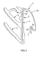
- In a known manner and as visible in
Figure 1 showing the prior art, outer belt strip seals 1 with bright bead surfaces comprise a mainpolymeric leg 2 which is reinforced over its whole vertical width by ametal carrier 3 having an asymmetrical substantially U-shaped cross-section. Thismetal carrier 3 has a first branch 3a embedded in thisleg 2, which is provided on one side thereof with flockedinner sealing lips second branch 3b ending with a lowerouter lip 7 for sealing with the door frame. -
US Patent 6,422,571 discloses in itsFigure 3 an outer belt strip seal obtained by coextrusion, onto and around a metal carrier, of an elastomeric material such as an EPDM for both the main part of the leg and the inner sealing lips and of an ionomer material for an upper section of the leg and forming the outer bright decorative surface of the strip seal. Contrary to instant above-referredFigure 1 , both branches of the metal carrier are embedded in the strip seal, with in particular the second branch being entirely embedded in this ionomer material. - Current designs of outer belt strip seals with a bright bead, such as the one illustrated in
Figure 1 , require: - as a first solution, a separate roll formed and finished decorative strip, with a bright bead that is attached to the sealing portion of the belt, or
- as a second solution illustrated in
Figure 1 , a single sealing and decorative strip 1, where the embeddedmetal carrier 3 has an adhesive applied only to specificdistinct areas metal carrier 3 being said in this case to be "stripe coated" onareas main leg 2 must adhere and further onareas second branch 3b to which the elastomeric material of thelower lip 7 must also adhere), and afterwards this stripe coatedmetal carrier 3 is roll formed. - The main drawbacks of this first solution implying a two-piece design are that it is costly, involves a high amount of scrap and additional assembly time, and also an additional weight.
- Concerning this second solution, the
metal carrier 3, which is typically wide enough to reinforce the sealingportion main leg . 2 and theouter sealing lip 7 are extruded ontoareas -
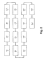
Figure 2 shows a known manufacturing method of this strip seal 1, with the following successive steps: - a
step 10 of stripe abrading the metal for thecarrier 3, - a
step 20 of stripe applying a primer to this abraded metal, - a
step 30 of curing this metal with an applied primer, - a
step 40 of stripe applying adhesive to the cured metal, - a
step 50 of curing the stripe adhesive coated metal, - a
step 60 of roll forming the cured stripe coated metal, - a
step 70 of co-extruding the rigid and flexible polymeric materials respectively forming themain leg 2 and thesealing lips - a
step 80 of calibrating the obtained coextruded blank, - a step 90 of cooling the calibrated blank,
- a
step 100 of applying adhesive to the cooled blank, - a
step 110 of applying a flock to bothinner lips - a
step 120 of curing the seal with flockedinner lips - a
step 130 of cutting off the cured seal to length, and - a
step 140 of curing the cut-off seal. - The main drawbacks of this second solution with the
stripe coating operations 10 to 50 for themetal carrier 3, apart from also being costly and involving a high amount of scrap, are that these operations produce volatile organic compounds (VOC's) and require a wider stock. - It is an object of the present invention to provide a strip seal for a motor vehicle, which may be advantageously coextruded and remedies the aforementioned drawbacks and in particular eliminates the requirement of stripe coating the metal carrier.
- It is also an object of the present invention to provide such a strip seal which functions as both a sealing strip and decorative trim.
- An additional object of the present invention is to provide such a strip seal with a reduced weight due to a narrower metal carrier.
- It is further an object of the present invention to provide a manufacturing method for such a strip seal which involves a lower product cost due to elimination of this stripe coating operations and also due to a reduction in the metal carrier width, compared to the product cost of the known strip seals with stripe coating operations applied to a wider carrier.
- Another object of the present invention is to provide for this manufacturing method both a reduced scrap and a higher product quality compared to these known strip seals having uneven overlapping lines of stripe coated adhesive.
- Still another object of the present invention is to provide for this manufacturing method the elimination of volatile organic compounds which are present in the known manufacturing methods using stripe coating.
- A weather strip seal for an automotive vehicle of the invention is provided for sealing between first and second structures and comprises:
- a main leg made of at least one polymeric material, said main leg having one side and another side and terminating in a first end and second end,
- a first sealing portion which is designed to sealingly press against said first structure and which extends on said one side of said main leg adjacent said first end, and
- a metal carrier for retaining the shape of said strip seal which has an asymmetrical substantially U-shaped cross-section having a first branch which reinforces at least one portion of said main leg and a second branch which extends from said second end on said another side and terminates in a second sealing portion designed to sealingly press against said second structure, said metal carrier having a metal surface.
- To achieve all the above-recited objects in this strip seal of the invention, said metal carrier is provided on at least said first branch with at least one ionomer tie layer located between said metal surface and said at least one polymeric material, which makes the latter adhere to said metal surface.
- Advantageously, said at least one ionomer tie layer may consist of a single continuous layer coextruded with said at least one polymeric material onto said metal carrier, said ionomer tie layer preferably having a thickness of between 0.1 mm and 0.3mm.
- Also advantageously, the metal surface is devoid of any stripe coating adhesive to make it adhere to said at least one polymeric material.
- Preferably, said ionomer tie layer is based on at least one metal salt ionomer consisting of a metal salt of ethylene-methacrylic acid (E/MAA), even more preferably a zinc salt of said acid.
- According to a preferred embodiment of the invention, said at least one polymeric material comprises:
- at least one rigid thermoplastic material which extends along said main leg from said first end to an end section of said first branch by adhesively surrounding said end section by intercalation of said ionomer tie layer, and
- at least one flexible elastomeric material which forms an intermediate sealing portion of said main leg adjacent said second end, said intermediate sealing portion adhering to said first branch by intercalation of said ionomer tie layer and extending on said one side of said main leg so as to be in contact with said first sealing portion when the latter sealingly presses against said first structure.
- Advantageously, said metal carrier may not be embedded in said main leg except in said end section of said first branch, so that said first branch defines said another side of said main leg between said end section and said second end of said main leg.
- Also advantageously, said at least one flexible elastomeric material may also constitute said first sealing portion.
- According to another feature of the invention, said first sealing portion may comprise at least two primary sealing flocked lips which are designed to sealingly press against said first structure, one of which, or primary lower lip, extending adjacent said first end and the other one of which, or primary upper lip, extending between said first end and said second end and terminating in a secondary upper lip which is directed toward said one side facing said second end and which may be coated with a low friction coextruded coating.
- According to still another feature of the invention, said intermediate sealing portion has a surface defining said one side of said main leg upwards from said at least one rigid thermoplastic material, and this intermediate sealing portion may terminate in an upper sealing lip being in contact with said secondary upper lip when said upper primary lip sealingly presses against said first structure.
- Preferably, said at least one rigid thermoplastic material is based on at least one polyolefin which is preferably polypropylene, and further comprises an inorganic filler which is preferably talc.
- Still preferably, said at least one flexible elastomeric material is based on at least one elastomer selected from the group consisting of ethylene-propylene-diene rubbers (EPDM) and thermoplastic elastomers (TPE) and, even more preferably, is based on a thermoplastic elastomer (TPE) selected from the group consisting of thermoplastic vulcanizates (TPV) and styrene block thermoplastic elastomers (TPS).
- Advantageously, said at least one portion of the leg which is reinforced by said first branch of the metal carrier may have a width, viewed in a cross-section of the strip seal, which is less than the half-width of the leg.
- Also advantageously, said end section of said first branch may be curved substantially at right angle toward said one side of said main leg, said end section being preferably provided inside a bead section of said main leg which is formed by said at least one rigid thermoplastic material.
- In a preferred embodiment of the invention, the weather strip seal forms an outer belt strip seal, the first structure being a window pane of the vehicle, the second structure being a door frame outside the window pane, and the first end and second end of the main leg respectively forming lower and upper ends of the strip seal. Even more preferably, the first branch of the metal carrier extends in a substantially straight manner over said at least one portion of the main leg with a width, viewed in a cross-section of the strip seal, which is less than the third part of the main leg width, the second branch extending in a curved manner from the first branch and terminating in a lower sealing lip forming the second sealing portion.
- Advantageously, said second sealing portion may be made of an ionomer material which directly coats both faces of a curved end of said second branch and which is preferably the same as that of said tie layer.
- The method of the invention for manufacturing said weather strip seal comprises the following steps:
- a) roll forming said metal carrier, and
- b) coextruding the ionomer tie layer onto the roll formed carrier over said at least one portion of the main leg, and said at least one polymeric material onto the ionomer tie layer and around said portion, so that the coextruded ionomer tie layer makes said at least one polymeric material adhere to the metal carrier, a seal blank being obtained by this coextrusion.
- According to a preferred embodiment of the invention, this method further comprises, after steps a) and b):
- c) calibrating this co-extruded strip seal blank,
- d) cooling the calibrated strip seal blank, so that it keeps its final configuration, and
- e) curing and cutting to length the strip seal thus obtained.
- Other advantages, characteristics, and details of the invention appear from the following additional description with reference to the accompanying drawings, given purely by way of example, and in which:
-
Figure 1 is a cross-sectional view of an outer belt strip seal for a side window of a motor vehicle, according to the prior art. -
Figure 2 is a block diagram of the prior art showing the main steps for manufacturing an outer belt strip seal such as that ofFigure 1 . -
Figure 3 is a cross-sectional view of an outer belt strip seal for a side window of a motor vehicle according to an embodiment of the invention. -
Figure 4 is a block diagram of the invention showing the main steps for manufacturing an outer belt strip seal such as that ofFigure 3 . - The
strip seal 101 of instantFigure 3 is for an outer belt such as the outer belt identified inFigure 1 ofUS Patent 6,422,571 showing its well-known location for example on a front door of an automotive vehicle. - Referring to instant
Figure 3 , the coextruded outerbelt strip seal 101 of the invention is provided for sealing between a window pane of the vehicle and a door frame outside the window pane, and comprises: - a vertical
main leg 102 having aninner side 102a directed toward the window pane and anouter side 102b directed toward the door frame and terminating in alower end 102c andupper end 102d, theleg 102 being made from itslower end 102c to abead section 102e adjacent itsupper end 102d of a rigid polyolefin material M1, - an inner
elastomeric sealing portion 103 which extends on theinner side 102a ofleg 102 to sealingly press against the window pane, thisportion 103 having a lower flockedlip 103a obliquely extending from thelower end 102c and an upper flockedlip 103b which obliquely extends adjacent and from below thebead section 102e and which terminates in a secondaryupper lip 103c formed on its upper non flocked surface, thissecondary lip 103c being directed toward theinner side 102a to face theupper end 102d and being coated on its upper surface with a lowfriction coextruded coating 103d to be in contact in operation with a flexible elastomeric intermediateupper lip 103e formed on theinner side 102a of theupper end 102d, and - a
metal carrier 104 having an asymmetrical U-shaped cross-section having an innerfirst branch 104a which reinforces only an upper portion ofleg 102 extending from itsbead section 102e to itsupper end 102d, and an outersecond branch 104b which extends from theupper end 102d toward the outside and terminates in an outerlower sealing lip 105 designed to press against the door frame. - According to the invention, the
metal carrier 104 is provided on itsinner branch 104a with a coextruded continuousionomer tie layer 106 located between itsmetal surface 104 and both the rigid polyolefin material M1 ofleg 102 and the flexible elastomeric material M2 of theupper lip 103e, thistie layer 106 having a thickness of about 0.2mm and being coextruded with both materials M1 and M2 onto themetal carrier 104 and making them adhere to this metal surface without any application of a stripe coating adhesive. - More precisely, the
inner branch 104a ofmetal carrier 104 extends in a straight vertical manner over the upper portion ofleg 102 ending at thebead section 102e, which is defined by a protrusion provided on theinner face 102a ofleg 102 and in whichbead section 102e, made of a rigid polyolefin material, is embedded anend section 104c of theinner branch 104a. Thisend section 104c is curved at right angle toward theinner side 102a ofleg 102 and theionomer tie layer 106 covers thewhole metal surface 104 of thiscurved end section 104c. As visible inFigure 3 , the rigid polyolefin material M1 adhesively surrounds theend section 104c at thebead section 102e by intercalation of theionomer tie layer 106. And upwards from thisbead section 102e (i.e. in the upper portion ofleg 102 made of the flexible elastomeric material M2), theinner branch 104a is not embedded in this flexible material M2 but is covered by it on its inner face so that thisinner branch 104a defines theouter side 102b ofleg 102 between thebead section 102e and theupper end 102d. - As also shown by
Figure 3 , the inner face ofinner branch 104a is continuously covered by theionomer tie layer 106 from itsend section 104c to theupper end 102d, whichtie layer 106 is in turn covered by the flexible elastomeric material M2 in the shape of a flat coating ending in the intermediateupper lip 103e directed inwards. This intermediateupper lip 103e further coats, with the continuous intercalation of the sameionomer tie layer 106, a curved upper section orsummit 104d of theU-shaped metal carrier 104 which connects its inner andouter branches - According to an advantageous aspect of the invention, the
inner branch 104a has a cross-sectional vertical width which is very small, compared to the total vertical width ofleg 102, being preferably less than the third part of the total leg width. It is to be noted that the rigid polyolefin material M1 of the portion ofleg 102 extending from itslower end 102c to itsbead section 102e thus acts as the major reinforcement for theleg 102 to support theinner sealing lips - As for the
outer branch 104b of themetal carrier 104, it extends in a curved manner from thesummit 104d and terminates in an inwardcurved part 104e supporting the outerlower sealing lip 105, whichlip 105 is made of an ionomer material - for example the same as that of the tie layer 106 - directly and continuously coating both faces of thiscurved part 104e (i.e. by means of no adhesive intermediate layer). - This
ionomer tie layer 106 and outerlower sealing lip 105 are based on a metal salt ionomer (i.e. by a polymer with covalent bonds between the elements of the chain and ionic bonds between the chains) which is preferably a zinc salt of ethylene-methacrylic acid (E/MAA), although other salts are usable. By way of non-limiting examples, may be used ionomers having a Durometer Hardness Shore D ranging from 30 to 65, measured according to ASTM D2240 standard. Mention may be made for instance of ionomers sold by A. Schulman under the trade name "Clarix" or by Dupont under the trade name "Surlyn". - The outer
lower sealing lip 105 was made of the same ionomer material as that of thistie layer 106, i.e. such as said zinc salt (this ionomer possibly being pigmented to match, contrast or blend with the remainder of the vehicle body). - The metal used for the
carrier 104 was a "436 M2" stainless steel. - The rigid polyolefin based material M1 used for the major part of
leg 102 was a polypropylene sold under the trade name "Salflex 620TC", and this polypropylene was filled with 20%-30% of an inorganic filler, such as talc, and further comprised "Sequel E5000" and "Hostacom" as other ingredients. - The flexible elastomeric material M2 used for the intermediate
upper lip 103e adhering to the ionomer tie layer 106 - and also for example for both the lower andupper sealing lips tie layer 106. - The
flock material 103f used for each lower andupper sealing lip - The low
friction coextruded coating 103d ("LFCC") of thesecondary lip 103c was a TPV sold by Exxon Mobil under the trade name "Santoprene 8123-45S100". -
Figure 4 shows the inventive manufacturing method of such astrip seal 101 according to the invention, with the following successive steps: - a
step 150 of roll forming the metal, - a
step 160 of coextruding theionomer material 106 /flexible elastomeric material M2 / rigid polyolefin material M1 onto the roll formedmetal 104, - a
step 170 of calibrating the obtained coextruded blank, - a
step 180 of cooling the calibrated blank, - a
step 190 of applying adhesive to the cooled blank, - a
step 200 of applying aflock 103f to bothinner lips - a
step 210 of curing the seal with flockedinner lips - a step .220 of cutting off the cured seal to length, and
- a
step 230 of curing the cut-off seal 101. - As explained above, this inventive method in particular allows to do without any stripe coating operation applied to the
metal carrier 104, with all the recited advantages. - While the invention has been described in connection with specific embodiments thereof, it is evident that many alternatives, modifications, and variations will be apparent to those skilled in the art in light of the foregoing description. Accordingly, it is intended to embrace all such alternatives, modifications and variations that fall within the spirit and broad scope of the appended claims.
Claims (15)
- A weather strip seal (101) for an automotive vehicle which is provided for sealing between a first structure and a second structure and which comprises:a main leg (102) made of at least one polymeric material, said main leg having one side (102a) and another side (102b) and terminating in a first end (102c) and second end (102d),a first sealing portion (103) which is designed to sealingly press against said first structure and which extends on said one side of said main leg adjacent said first end, anda metal carrier (104) for retaining the shape of said strip seal which has an asymmetrical substantially U-shaped cross-section having a first branch (104a) which reinforces at least one portion of said main leg and a second branch (104b) which extends from said second end on said another side and terminates in a second sealing portion (105) designed to sealingly press against said second structure, said metal carrier having a metal surface,characterized in that said metal carrier is provided on at least said first branch with at least one ionomer tie layer (106) located between said metal surface and said at least one polymeric material, which makes the latter adhere to said metal surface.
- A weather strip seal (101) according to claim 1, wherein said at least one ionomer tie layer (106) consists of a single continuous layer coextruded with said at least one polymeric material onto said metal carrier (104), said ionomer tie layer preferably having a thickness of between 0.1 mm and 0.3mm.
- A weather strip seal (101) according to claim 1 or 2, wherein said metal surface is devoid of any stripe coating adhesive to make it adhere to said at least one polymeric material.
- A weather strip seal (101) according to any of the preceding claims, wherein said at least one ionomer tie layer (106) is based on at least one metal salt ionomer consisting of a metal salt of ethylene-methacrylic acid (E/MAA), preferably a zinc salt of said acid.
- A weather strip seal (101) according to any of the preceding claims, wherein said at least one polymeric material comprises:at least one rigid thermoplastic material (M1) which extends along said main leg (102) from said first end (102c) to an end section (104c) of said first branch (104a) by adhesively surrounding said end section by intercalation of said at least one ionomer tie layer (106), and which is preferably based on at least one polyolefin which is preferably polypropylene, and further comprises an inorganic filler which is preferably talc, andat least one flexible elastomeric material (M2) which forms an intermediate sealing portion of said main leg adjacent said second end (102d), said intermediate sealing portion adhering to said first branch (104a) by intercalation of said at least one ionomer tie layer and extending on said one side (102a) of said main leg so as to be in contact with said first sealing portion (103) when the latter sealingly presses against said first structure, said at least one flexible elastomeric material being preferably based on at least one elastomer selected from the group consisting of ethylene-propylene-diene rubbers (EPDM) and thermoplastic elastomers (TPE), such as a thermoplastic elastomer (TPE) selected from the group consisting of thermoplastic vulcanizates (TPV) and styrene block thermoplastic elastomers (TPS).
- A weather strip seal (101) according to claim 5, wherein said metal carrier (104) is not embedded in said main leg (102) except in said end section (104c) of said first branch (104a), so that said first branch defines said another side (102b) of said main leg between said end section and said second end (102d) of said main leg.
- A weather strip seal (101) according to claim 5 or 6, wherein said at least one flexible elastomeric material (M2) also constitutes said first sealing portion (103).
- A weather strip seal (101) according to any of the preceding claims, wherein said first sealing portion (103) comprises at least two primary sealing flocked lips (103a and 103b) which are designed to sealingly press against said first structure, one of which, or primary lower lip (103a), extending adjacent said first end (102c) and the other one of which, or primary upper lip (103b), extending between said first end and said second end (102d) and terminating in a secondary upper lip (103c) which is directed toward said one side (102a) facing said second end and which is coated with a low friction coextruded coating (103d).
- A weather strip seal (101) according to claims 5 and 8, wherein said intermediate sealing portion (M2) has a surface defining said one side (102a) of said main leg (102) upwards from said at least one rigid thermoplastic material (M1), and terminates in an upper sealing lip (103e) being in contact with said secondary upper lip (103c) when said upper primary lip (103b) sealingly presses against said first structure.
- A weather strip seal (101) according to any of the preceding claims, wherein said at least one portion of said main leg (102) which is reinforced by said first branch (104a) of said metal carrier (104) has a width, viewed in a cross-section of said weather strip seal, which is less than the half-width of said main leg.
- A weather strip seal (101) according to claims 5 and 10, wherein said end section (104c) of said first branch (104a) is curved substantially at right angle toward said one side (102a) of said main leg (102), said end section being provided inside a bead section (102e) of said main leg which is formed by said at least one rigid thermoplastic material (M1).
- A weather strip seal (101) according to any of the preceding claims, wherein it forms an outer belt strip seal, said first structure being a window pane of said vehicle, said second structure being a door frame outside said window pane, and said first end (102c) and second end (102d) of said main leg (102) respectively forming lower and upper ends of said strip seal.
- A weather strip seal (101) according to claim 12, wherein said first branch (104a) of said metal carrier (104) extends in a substantially straight manner over said at least one portion of said main leg (102) with a width, viewed in a cross-section of said weather strip seal, which is less than the third part of the width of said main leg, said second branch (104b) extending in a curved manner from said first branch and terminating in a lower sealing lip (105) forming said second sealing portion.
- A weather strip seal (101) according to any of the preceding claims, wherein said second sealing portion (105) is made of an ionomer material which directly coats both faces of a curved end of said second branch (104b) and which is preferably the same as that of said at least one ionomer tie layer (106).
- Method for manufacturing a weather strip seal (101) for a motor vehicle according to any of the preceding claims, characterized in that it comprises the following steps:a) roll forming (150) said metal carrier, andb) coextruding (160) said at least one ionomer tie layer (106) onto the roll formed metal carrier (104) over said at least one portion of said main leg (102), and said at least one polymeric material onto said at least one ionomer tie layer and around said portion, so that this coextruded ionomer tie layer makes said at least one polymeric material adhere to said metal carrier, a strip seal blank being obtained by this coextrusion,
and preferably in that it further comprises, after steps a) and b):c) calibrating (170) this co-extruded strip seal blank,d) cooling (180) the calibrated strip seal blank, so that it keeps its final configuration, ande) curing (210,230) and cutting (220) the strip seal thus obtained to the required length.
Priority Applications (1)
| Application Number | Priority Date | Filing Date | Title |
|---|---|---|---|
| PL12177494T PL2551138T3 (en) | 2011-07-27 | 2012-07-23 | A weather strip seal for an automotive vehicle, and its manufacturing method |
Applications Claiming Priority (1)
| Application Number | Priority Date | Filing Date | Title |
|---|---|---|---|
| US201161512146P | 2011-07-27 | 2011-07-27 |
Publications (2)
| Publication Number | Publication Date |
|---|---|
| EP2551138A1 true EP2551138A1 (en) | 2013-01-30 |
| EP2551138B1 EP2551138B1 (en) | 2015-04-08 |
Family
ID=46551420
Family Applications (1)
| Application Number | Title | Priority Date | Filing Date |
|---|---|---|---|
| EP12177494.7A Revoked EP2551138B1 (en) | 2011-07-27 | 2012-07-23 | A weather strip seal for an automotive vehicle, and its manufacturing method |
Country Status (6)
| Country | Link |
|---|---|
| US (1) | US8881463B2 (en) |
| EP (1) | EP2551138B1 (en) |
| CA (1) | CA2783643A1 (en) |
| ES (1) | ES2544834T3 (en) |
| MX (1) | MX2012008771A (en) |
| PL (1) | PL2551138T3 (en) |
Cited By (3)
| Publication number | Priority date | Publication date | Assignee | Title |
|---|---|---|---|---|
| US11338659B2 (en) | 2019-04-04 | 2022-05-24 | Hutchinson Sealing Systems | Method of making a weather strip and bright strip assembly for a vehicle door |
| US11697333B2 (en) * | 2019-04-24 | 2023-07-11 | Hyundai Motor Company | Door outside belt for vehicle |
| US20240123802A1 (en) * | 2021-03-04 | 2024-04-18 | Audi Ag | Window pane assembly for a vehicle |
Families Citing this family (16)
| Publication number | Priority date | Publication date | Assignee | Title |
|---|---|---|---|---|
| DE102013009213A1 (en) * | 2013-05-31 | 2014-12-04 | Volkswagen Aktiengesellschaft | weatherstrip |
| CN106061779B (en) | 2014-02-07 | 2018-01-23 | 瀚德汽车密封系统北美有限公司 | Vehicle seal assembly and method of manufacturing the same |
| JP2017051404A (en) * | 2015-09-09 | 2017-03-16 | 株式会社ユニバーサルエンターテインメント | Gaming machine |
| KR102249760B1 (en) * | 2015-11-19 | 2021-05-07 | 현대자동차주식회사 | A weather strip for door of cars |
| JP6407899B2 (en) * | 2016-01-29 | 2018-10-17 | 株式会社ファルテック | Molding |
| WO2017200650A2 (en) * | 2016-04-04 | 2017-11-23 | Cooper-Standard Automotive Inc. | Weatherstrip assembly and method of isolating dissimilar metals in the weatherstrip assembly |
| DE102016218755B3 (en) * | 2016-09-28 | 2017-11-23 | Süddeutsche Aluminium Manufaktur GmbH | Window channel strip arrangement |
| WO2018161068A1 (en) * | 2017-03-03 | 2018-09-07 | Henniges Automotive Sealing Systems North America, Inc. | Seal assembly with a decorative trim member |
| DE102017126725A1 (en) * | 2017-11-14 | 2019-05-16 | Henniges Automotive Gmbh & Co. Kg | Sealing profile for the sealing of a surface element in a building, in particular for the sealing of a disc in a motor vehicle body |
| DE102019111877A1 (en) * | 2019-05-07 | 2020-11-12 | Volkswagen Aktiengesellschaft | Strip-shaped seal for a vehicle, vehicle |
| JP7190996B2 (en) * | 2019-10-30 | 2022-12-16 | 株式会社ファルテック | vehicle molding |
| JP7475197B2 (en) * | 2020-05-15 | 2024-04-26 | 東海興業株式会社 | Joining sheet material for weather strips, weather strips and manufacturing method thereof |
| CN112063058A (en) * | 2020-08-31 | 2020-12-11 | 兴宇汽车零部件股份有限公司 | Low-VOC rubber sealing strip and preparation method thereof |
| US12202321B2 (en) * | 2021-03-18 | 2025-01-21 | Tokai Kogyo Co., Ltd. | Belt molding |
| US12319130B2 (en) * | 2021-10-14 | 2025-06-03 | Jaguar Land Rover Limited | Vehicle door assembly |
| GB2611778B (en) * | 2021-10-14 | 2024-07-17 | Jaguar Land Rover Ltd | A waist seal |
Citations (4)
| Publication number | Priority date | Publication date | Assignee | Title |
|---|---|---|---|---|
| EP0437974A2 (en) * | 1990-01-18 | 1991-07-24 | The Standard Products Company | One-piece weatherstrip with smooth cross-section at corner bends |
| EP0721856A2 (en) * | 1995-01-12 | 1996-07-17 | Hutchinson | Sealing profile and method for making the same |
| US6370824B1 (en) * | 2000-05-10 | 2002-04-16 | Hutchinson Sealing Systems, Inc. | Automotive vehicle seal with decorative trim sealing surface |
| US6422571B1 (en) | 2000-04-26 | 2002-07-23 | Hutchinson Sealing Systems, Inc. | Automotive vehicle seal and decorative trim strip |
Family Cites Families (12)
| Publication number | Priority date | Publication date | Assignee | Title |
|---|---|---|---|---|
| US3904569A (en) | 1972-10-26 | 1975-09-09 | Continental Can Co | Metal coating compositions prepared from aqueous dispersions of carboxylic acid resin and an aliphatic polyamine |
| AU541318B2 (en) | 1981-04-23 | 1985-01-03 | Kinugawa Rubber Industrial Co., Ltd. | Window sealing strip |
| JPH01175918U (en) | 1988-05-26 | 1989-12-14 | ||
| JP2597299Y2 (en) * | 1992-06-11 | 1999-07-05 | 豊田合成株式会社 | Automotive weather strip |
| US6217807B1 (en) * | 1998-03-13 | 2001-04-17 | Tokiwa Chemical Industries, Co., Ltd | Molding for automobile and its manufacturing method |
| US6652952B2 (en) | 2001-07-23 | 2003-11-25 | Cooper Technology Services, Llc | Extrusion having thermoplastic elastomer co-extruded on core with additional ionomeric show surface |
| DE10259843B3 (en) | 2002-12-19 | 2004-08-26 | Metzeler Automotive Profile Systems Gmbh | Sealing arrangement, in particular for sealing window panes of a motor vehicle |
| US20050235569A1 (en) | 2004-04-27 | 2005-10-27 | Cooper Technology Services, Llc | Weatherseal with imroved show surface |
| US7484287B2 (en) * | 2004-09-10 | 2009-02-03 | Tokai Kogyo Company Limited | Apparatus for assembling flexible molding main body part and cover part as molding |
| DE102005022582B4 (en) | 2005-05-09 | 2008-04-03 | Decoma (Germany) Gmbh | Cover strip and sealing arrangement |
| DE202007003837U1 (en) | 2007-03-15 | 2007-05-24 | Meteor Gummiwerke K.H. Bädje GmbH & Co. KG | Sealing profile for vehicle door window has u-shaped fixing section and sealing section with multiple lips |
| EP2244877A4 (en) * | 2008-02-14 | 2013-01-23 | Cooper Standard Automotive Inc | Extrudable polymer for bonding metal to rubber and thermoplastic polymers |
-
2012
- 2012-07-19 CA CA2783643A patent/CA2783643A1/en not_active Abandoned
- 2012-07-23 PL PL12177494T patent/PL2551138T3/en unknown
- 2012-07-23 ES ES12177494.7T patent/ES2544834T3/en active Active
- 2012-07-23 US US13/555,627 patent/US8881463B2/en not_active Expired - Fee Related
- 2012-07-23 EP EP12177494.7A patent/EP2551138B1/en not_active Revoked
- 2012-07-27 MX MX2012008771A patent/MX2012008771A/en active IP Right Grant
Patent Citations (4)
| Publication number | Priority date | Publication date | Assignee | Title |
|---|---|---|---|---|
| EP0437974A2 (en) * | 1990-01-18 | 1991-07-24 | The Standard Products Company | One-piece weatherstrip with smooth cross-section at corner bends |
| EP0721856A2 (en) * | 1995-01-12 | 1996-07-17 | Hutchinson | Sealing profile and method for making the same |
| US6422571B1 (en) | 2000-04-26 | 2002-07-23 | Hutchinson Sealing Systems, Inc. | Automotive vehicle seal and decorative trim strip |
| US6370824B1 (en) * | 2000-05-10 | 2002-04-16 | Hutchinson Sealing Systems, Inc. | Automotive vehicle seal with decorative trim sealing surface |
Cited By (4)
| Publication number | Priority date | Publication date | Assignee | Title |
|---|---|---|---|---|
| US11338659B2 (en) | 2019-04-04 | 2022-05-24 | Hutchinson Sealing Systems | Method of making a weather strip and bright strip assembly for a vehicle door |
| US11697333B2 (en) * | 2019-04-24 | 2023-07-11 | Hyundai Motor Company | Door outside belt for vehicle |
| US20240123802A1 (en) * | 2021-03-04 | 2024-04-18 | Audi Ag | Window pane assembly for a vehicle |
| US12103367B2 (en) * | 2021-03-04 | 2024-10-01 | Audi Ag | Window pane assembly for a vehicle |
Also Published As
| Publication number | Publication date |
|---|---|
| EP2551138B1 (en) | 2015-04-08 |
| MX2012008771A (en) | 2013-03-27 |
| US8881463B2 (en) | 2014-11-11 |
| US20130026717A1 (en) | 2013-01-31 |
| ES2544834T3 (en) | 2015-09-04 |
| PL2551138T3 (en) | 2015-10-30 |
| CA2783643A1 (en) | 2013-01-27 |
Similar Documents
| Publication | Publication Date | Title |
|---|---|---|
| EP2551138B1 (en) | A weather strip seal for an automotive vehicle, and its manufacturing method | |
| KR100349822B1 (en) | Flush Glass Sealing System | |
| CA2791940C (en) | Co-extruded roll formed bright extrusion with integral end forms | |
| US20090121378A1 (en) | Heat fromad TPV co-extruded Header trim | |
| US20060103047A1 (en) | Vehicular division bar assembly free of structural metal | |
| WO2008157332A1 (en) | Integrated metal cosmetic strip to outerbelt, glass run, and upper reveal | |
| EP0684158B1 (en) | Flexible sealing unit for movable windows | |
| JP2010149838A (en) | Opening trim weatherstrip for automobile | |
| US7687133B2 (en) | Weather strip | |
| JP2008087495A (en) | Weatherstrip for automobile | |
| US20100263292A1 (en) | Multi-material layered extrusion | |
| JP2011111109A (en) | Weather strip with water stop sponge, and method for manufacturing the same | |
| JP2006205846A (en) | Weather strip for automobile | |
| JP4407469B2 (en) | Weather strip for automobile | |
| JP2010126066A (en) | Weather strip for automobile | |
| JP2010155515A (en) | Weather strip for automobile | |
| JP2006205847A (en) | Weather strip for automobile | |
| JP2007152978A (en) | Weather strip for automobile | |
| JP2004034915A (en) | Weather strip incorporating iron core |
Legal Events
| Date | Code | Title | Description |
|---|---|---|---|
| PUAI | Public reference made under article 153(3) epc to a published international application that has entered the european phase |
Free format text: ORIGINAL CODE: 0009012 |
|
| AK | Designated contracting states |
Kind code of ref document: A1 Designated state(s): AL AT BE BG CH CY CZ DE DK EE ES FI FR GB GR HR HU IE IS IT LI LT LU LV MC MK MT NL NO PL PT RO RS SE SI SK SM TR |
|
| AX | Request for extension of the european patent |
Extension state: BA ME |
|
| 17P | Request for examination filed |
Effective date: 20130610 |
|
| RBV | Designated contracting states (corrected) |
Designated state(s): AL AT BE BG CH CY CZ DE DK EE ES FI FR GB GR HR HU IE IS IT LI LT LU LV MC MK MT NL NO PL PT RO RS SE SI SK SM TR |
|
| RIC1 | Information provided on ipc code assigned before grant |
Ipc: B60J 10/00 20060101ALI20140912BHEP Ipc: B60J 10/04 20060101AFI20140912BHEP |
|
| GRAP | Despatch of communication of intention to grant a patent |
Free format text: ORIGINAL CODE: EPIDOSNIGR1 |
|
| INTG | Intention to grant announced |
Effective date: 20141028 |
|
| GRAS | Grant fee paid |
Free format text: ORIGINAL CODE: EPIDOSNIGR3 |
|
| GRAA | (expected) grant |
Free format text: ORIGINAL CODE: 0009210 |
|
| AK | Designated contracting states |
Kind code of ref document: B1 Designated state(s): AL AT BE BG CH CY CZ DE DK EE ES FI FR GB GR HR HU IE IS IT LI LT LU LV MC MK MT NL NO PL PT RO RS SE SI SK SM TR |
|
| REG | Reference to a national code |
Ref country code: GB Ref legal event code: FG4D |
|
| REG | Reference to a national code |
Ref country code: CH Ref legal event code: EP |
|
| REG | Reference to a national code |
Ref country code: IE Ref legal event code: FG4D |
|
| REG | Reference to a national code |
Ref country code: AT Ref legal event code: REF Ref document number: 720268 Country of ref document: AT Kind code of ref document: T Effective date: 20150515 |
|
| REG | Reference to a national code |
Ref country code: DE Ref legal event code: R096 Ref document number: 602012006429 Country of ref document: DE Effective date: 20150521 |
|
| REG | Reference to a national code |
Ref country code: FR Ref legal event code: PLFP Year of fee payment: 4 |
|
| REG | Reference to a national code |
Ref country code: AT Ref legal event code: MK05 Ref document number: 720268 Country of ref document: AT Kind code of ref document: T Effective date: 20150408 |
|
| REG | Reference to a national code |
Ref country code: NL Ref legal event code: VDEP Effective date: 20150408 |
|
| REG | Reference to a national code |
Ref country code: ES Ref legal event code: FG2A Ref document number: 2544834 Country of ref document: ES Kind code of ref document: T3 Effective date: 20150904 |
|
| REG | Reference to a national code |
Ref country code: LT Ref legal event code: MG4D |
|
| PG25 | Lapsed in a contracting state [announced via postgrant information from national office to epo] |
Ref country code: NL Free format text: LAPSE BECAUSE OF FAILURE TO SUBMIT A TRANSLATION OF THE DESCRIPTION OR TO PAY THE FEE WITHIN THE PRESCRIBED TIME-LIMIT Effective date: 20150408 |
|
| PG25 | Lapsed in a contracting state [announced via postgrant information from national office to epo] |
Ref country code: PT Free format text: LAPSE BECAUSE OF FAILURE TO SUBMIT A TRANSLATION OF THE DESCRIPTION OR TO PAY THE FEE WITHIN THE PRESCRIBED TIME-LIMIT Effective date: 20150810 Ref country code: LT Free format text: LAPSE BECAUSE OF FAILURE TO SUBMIT A TRANSLATION OF THE DESCRIPTION OR TO PAY THE FEE WITHIN THE PRESCRIBED TIME-LIMIT Effective date: 20150408 Ref country code: FI Free format text: LAPSE BECAUSE OF FAILURE TO SUBMIT A TRANSLATION OF THE DESCRIPTION OR TO PAY THE FEE WITHIN THE PRESCRIBED TIME-LIMIT Effective date: 20150408 Ref country code: HR Free format text: LAPSE BECAUSE OF FAILURE TO SUBMIT A TRANSLATION OF THE DESCRIPTION OR TO PAY THE FEE WITHIN THE PRESCRIBED TIME-LIMIT Effective date: 20150408 Ref country code: NO Free format text: LAPSE BECAUSE OF FAILURE TO SUBMIT A TRANSLATION OF THE DESCRIPTION OR TO PAY THE FEE WITHIN THE PRESCRIBED TIME-LIMIT Effective date: 20150708 |
|
| REG | Reference to a national code |
Ref country code: PL Ref legal event code: T3 |
|
| PG25 | Lapsed in a contracting state [announced via postgrant information from national office to epo] |
Ref country code: IS Free format text: LAPSE BECAUSE OF FAILURE TO SUBMIT A TRANSLATION OF THE DESCRIPTION OR TO PAY THE FEE WITHIN THE PRESCRIBED TIME-LIMIT Effective date: 20150808 Ref country code: RS Free format text: LAPSE BECAUSE OF FAILURE TO SUBMIT A TRANSLATION OF THE DESCRIPTION OR TO PAY THE FEE WITHIN THE PRESCRIBED TIME-LIMIT Effective date: 20150408 Ref country code: LV Free format text: LAPSE BECAUSE OF FAILURE TO SUBMIT A TRANSLATION OF THE DESCRIPTION OR TO PAY THE FEE WITHIN THE PRESCRIBED TIME-LIMIT Effective date: 20150408 Ref country code: AT Free format text: LAPSE BECAUSE OF FAILURE TO SUBMIT A TRANSLATION OF THE DESCRIPTION OR TO PAY THE FEE WITHIN THE PRESCRIBED TIME-LIMIT Effective date: 20150408 Ref country code: GR Free format text: LAPSE BECAUSE OF FAILURE TO SUBMIT A TRANSLATION OF THE DESCRIPTION OR TO PAY THE FEE WITHIN THE PRESCRIBED TIME-LIMIT Effective date: 20150709 |
|
| REG | Reference to a national code |
Ref country code: DE Ref legal event code: R026 Ref document number: 602012006429 Country of ref document: DE |
|
| PLBI | Opposition filed |
Free format text: ORIGINAL CODE: 0009260 |
|
| PG25 | Lapsed in a contracting state [announced via postgrant information from national office to epo] |
Ref country code: DK Free format text: LAPSE BECAUSE OF FAILURE TO SUBMIT A TRANSLATION OF THE DESCRIPTION OR TO PAY THE FEE WITHIN THE PRESCRIBED TIME-LIMIT Effective date: 20150408 Ref country code: EE Free format text: LAPSE BECAUSE OF FAILURE TO SUBMIT A TRANSLATION OF THE DESCRIPTION OR TO PAY THE FEE WITHIN THE PRESCRIBED TIME-LIMIT Effective date: 20150408 |
|
| PLAX | Notice of opposition and request to file observation + time limit sent |
Free format text: ORIGINAL CODE: EPIDOSNOBS2 |
|
| 26 | Opposition filed |
Opponent name: COOPER STANDARD GMBH Effective date: 20160108 |
|
| PG25 | Lapsed in a contracting state [announced via postgrant information from national office to epo] |
Ref country code: RO Free format text: LAPSE BECAUSE OF NON-PAYMENT OF DUE FEES Effective date: 20150408 Ref country code: CZ Free format text: LAPSE BECAUSE OF FAILURE TO SUBMIT A TRANSLATION OF THE DESCRIPTION OR TO PAY THE FEE WITHIN THE PRESCRIBED TIME-LIMIT Effective date: 20150408 Ref country code: SK Free format text: LAPSE BECAUSE OF FAILURE TO SUBMIT A TRANSLATION OF THE DESCRIPTION OR TO PAY THE FEE WITHIN THE PRESCRIBED TIME-LIMIT Effective date: 20150408 Ref country code: MC Free format text: LAPSE BECAUSE OF FAILURE TO SUBMIT A TRANSLATION OF THE DESCRIPTION OR TO PAY THE FEE WITHIN THE PRESCRIBED TIME-LIMIT Effective date: 20150408 |
|
| REG | Reference to a national code |
Ref country code: CH Ref legal event code: PL |
|
| PG25 | Lapsed in a contracting state [announced via postgrant information from national office to epo] |
Ref country code: LU Free format text: LAPSE BECAUSE OF FAILURE TO SUBMIT A TRANSLATION OF THE DESCRIPTION OR TO PAY THE FEE WITHIN THE PRESCRIBED TIME-LIMIT Effective date: 20150723 |
|
| REG | Reference to a national code |
Ref country code: IE Ref legal event code: MM4A |
|
| PG25 | Lapsed in a contracting state [announced via postgrant information from national office to epo] |
Ref country code: LI Free format text: LAPSE BECAUSE OF NON-PAYMENT OF DUE FEES Effective date: 20150731 Ref country code: IT Free format text: LAPSE BECAUSE OF FAILURE TO SUBMIT A TRANSLATION OF THE DESCRIPTION OR TO PAY THE FEE WITHIN THE PRESCRIBED TIME-LIMIT Effective date: 20150408 Ref country code: CH Free format text: LAPSE BECAUSE OF NON-PAYMENT OF DUE FEES Effective date: 20150731 |
|
| PG25 | Lapsed in a contracting state [announced via postgrant information from national office to epo] |
Ref country code: SI Free format text: LAPSE BECAUSE OF FAILURE TO SUBMIT A TRANSLATION OF THE DESCRIPTION OR TO PAY THE FEE WITHIN THE PRESCRIBED TIME-LIMIT Effective date: 20150408 |
|
| PLBB | Reply of patent proprietor to notice(s) of opposition received |
Free format text: ORIGINAL CODE: EPIDOSNOBS3 |
|
| REG | Reference to a national code |
Ref country code: FR Ref legal event code: PLFP Year of fee payment: 5 |
|
| PG25 | Lapsed in a contracting state [announced via postgrant information from national office to epo] |
Ref country code: IE Free format text: LAPSE BECAUSE OF NON-PAYMENT OF DUE FEES Effective date: 20150723 |
|
| PG25 | Lapsed in a contracting state [announced via postgrant information from national office to epo] |
Ref country code: BE Free format text: LAPSE BECAUSE OF FAILURE TO SUBMIT A TRANSLATION OF THE DESCRIPTION OR TO PAY THE FEE WITHIN THE PRESCRIBED TIME-LIMIT Effective date: 20150408 |
|
| PGFP | Annual fee paid to national office [announced via postgrant information from national office to epo] |
Ref country code: DE Payment date: 20160722 Year of fee payment: 5 |
|
| PGFP | Annual fee paid to national office [announced via postgrant information from national office to epo] |
Ref country code: FR Payment date: 20160713 Year of fee payment: 5 Ref country code: PL Payment date: 20160713 Year of fee payment: 5 |
|
| PGFP | Annual fee paid to national office [announced via postgrant information from national office to epo] |
Ref country code: TR Payment date: 20160714 Year of fee payment: 5 Ref country code: ES Payment date: 20160715 Year of fee payment: 5 |
|
| GBPC | Gb: european patent ceased through non-payment of renewal fee |
Effective date: 20160723 |
|
| PG25 | Lapsed in a contracting state [announced via postgrant information from national office to epo] |
Ref country code: MT Free format text: LAPSE BECAUSE OF FAILURE TO SUBMIT A TRANSLATION OF THE DESCRIPTION OR TO PAY THE FEE WITHIN THE PRESCRIBED TIME-LIMIT Effective date: 20150408 |
|
| PG25 | Lapsed in a contracting state [announced via postgrant information from national office to epo] |
Ref country code: SM Free format text: LAPSE BECAUSE OF FAILURE TO SUBMIT A TRANSLATION OF THE DESCRIPTION OR TO PAY THE FEE WITHIN THE PRESCRIBED TIME-LIMIT Effective date: 20150408 Ref country code: GB Free format text: LAPSE BECAUSE OF NON-PAYMENT OF DUE FEES Effective date: 20160723 Ref country code: BG Free format text: LAPSE BECAUSE OF FAILURE TO SUBMIT A TRANSLATION OF THE DESCRIPTION OR TO PAY THE FEE WITHIN THE PRESCRIBED TIME-LIMIT Effective date: 20150408 Ref country code: HU Free format text: LAPSE BECAUSE OF FAILURE TO SUBMIT A TRANSLATION OF THE DESCRIPTION OR TO PAY THE FEE WITHIN THE PRESCRIBED TIME-LIMIT; INVALID AB INITIO Effective date: 20120723 |
|
| PG25 | Lapsed in a contracting state [announced via postgrant information from national office to epo] |
Ref country code: SE Free format text: LAPSE BECAUSE OF FAILURE TO SUBMIT A TRANSLATION OF THE DESCRIPTION OR TO PAY THE FEE WITHIN THE PRESCRIBED TIME-LIMIT Effective date: 20150408 Ref country code: CY Free format text: LAPSE BECAUSE OF FAILURE TO SUBMIT A TRANSLATION OF THE DESCRIPTION OR TO PAY THE FEE WITHIN THE PRESCRIBED TIME-LIMIT Effective date: 20150408 |
|
| PLAY | Examination report in opposition despatched + time limit |
Free format text: ORIGINAL CODE: EPIDOSNORE2 |
|
| PLAT | Information related to reply to examination report in opposition deleted |
Free format text: ORIGINAL CODE: EPIDOSDORE3 |
|
| PLBC | Reply to examination report in opposition received |
Free format text: ORIGINAL CODE: EPIDOSNORE3 |
|
| PLAL | Information related to reply to examination report in opposition modified |
Free format text: ORIGINAL CODE: EPIDOSCORE3 |
|
| PLBC | Reply to examination report in opposition received |
Free format text: ORIGINAL CODE: EPIDOSNORE3 |
|
| RDAF | Communication despatched that patent is revoked |
Free format text: ORIGINAL CODE: EPIDOSNREV1 |
|
| REG | Reference to a national code |
Ref country code: DE Ref legal event code: R064 Ref document number: 602012006429 Country of ref document: DE Ref country code: DE Ref legal event code: R103 Ref document number: 602012006429 Country of ref document: DE |
|
| RDAG | Patent revoked |
Free format text: ORIGINAL CODE: 0009271 |
|
| STAA | Information on the status of an ep patent application or granted ep patent |
Free format text: STATUS: PATENT REVOKED |
|
| 27W | Patent revoked |
Effective date: 20171028 |
|
| PG25 | Lapsed in a contracting state [announced via postgrant information from national office to epo] |
Ref country code: AL Free format text: LAPSE BECAUSE OF FAILURE TO SUBMIT A TRANSLATION OF THE DESCRIPTION OR TO PAY THE FEE WITHIN THE PRESCRIBED TIME-LIMIT Effective date: 20150408 |
|
| PG25 | Lapsed in a contracting state [announced via postgrant information from national office to epo] |
Ref country code: ES Free format text: LAPSE BECAUSE OF NON-PAYMENT OF DUE FEES Effective date: 20170724 |