EP2551133A1 - Active suspension system - Google Patents
Active suspension system Download PDFInfo
- Publication number
- EP2551133A1 EP2551133A1 EP12173077A EP12173077A EP2551133A1 EP 2551133 A1 EP2551133 A1 EP 2551133A1 EP 12173077 A EP12173077 A EP 12173077A EP 12173077 A EP12173077 A EP 12173077A EP 2551133 A1 EP2551133 A1 EP 2551133A1
- Authority
- EP
- European Patent Office
- Prior art keywords
- vehicle
- gravity
- center
- controller
- actuators
- Prior art date
- Legal status (The legal status is an assumption and is not a legal conclusion. Google has not performed a legal analysis and makes no representation as to the accuracy of the status listed.)
- Granted
Links
Images
Classifications
-
- B—PERFORMING OPERATIONS; TRANSPORTING
- B60—VEHICLES IN GENERAL
- B60G—VEHICLE SUSPENSION ARRANGEMENTS
- B60G17/00—Resilient suspensions having means for adjusting the spring or vibration-damper characteristics, for regulating the distance between a supporting surface and a sprung part of vehicle or for locking suspension during use to meet varying vehicular or surface conditions, e.g. due to speed or load
- B60G17/015—Resilient suspensions having means for adjusting the spring or vibration-damper characteristics, for regulating the distance between a supporting surface and a sprung part of vehicle or for locking suspension during use to meet varying vehicular or surface conditions, e.g. due to speed or load the regulating means comprising electric or electronic elements
- B60G17/018—Resilient suspensions having means for adjusting the spring or vibration-damper characteristics, for regulating the distance between a supporting surface and a sprung part of vehicle or for locking suspension during use to meet varying vehicular or surface conditions, e.g. due to speed or load the regulating means comprising electric or electronic elements characterised by the use of a specific signal treatment or control method
- B60G17/0182—Resilient suspensions having means for adjusting the spring or vibration-damper characteristics, for regulating the distance between a supporting surface and a sprung part of vehicle or for locking suspension during use to meet varying vehicular or surface conditions, e.g. due to speed or load the regulating means comprising electric or electronic elements characterised by the use of a specific signal treatment or control method involving parameter estimation, e.g. observer, Kalman filter
-
- B—PERFORMING OPERATIONS; TRANSPORTING
- B60—VEHICLES IN GENERAL
- B60G—VEHICLE SUSPENSION ARRANGEMENTS
- B60G17/00—Resilient suspensions having means for adjusting the spring or vibration-damper characteristics, for regulating the distance between a supporting surface and a sprung part of vehicle or for locking suspension during use to meet varying vehicular or surface conditions, e.g. due to speed or load
- B60G17/015—Resilient suspensions having means for adjusting the spring or vibration-damper characteristics, for regulating the distance between a supporting surface and a sprung part of vehicle or for locking suspension during use to meet varying vehicular or surface conditions, e.g. due to speed or load the regulating means comprising electric or electronic elements
- B60G17/018—Resilient suspensions having means for adjusting the spring or vibration-damper characteristics, for regulating the distance between a supporting surface and a sprung part of vehicle or for locking suspension during use to meet varying vehicular or surface conditions, e.g. due to speed or load the regulating means comprising electric or electronic elements characterised by the use of a specific signal treatment or control method
-
- B—PERFORMING OPERATIONS; TRANSPORTING
- B60—VEHICLES IN GENERAL
- B60G—VEHICLE SUSPENSION ARRANGEMENTS
- B60G2400/00—Indexing codes relating to detected, measured or calculated conditions or factors
- B60G2400/60—Load
- B60G2400/63—Location of the center of gravity
-
- B—PERFORMING OPERATIONS; TRANSPORTING
- B60—VEHICLES IN GENERAL
- B60G—VEHICLE SUSPENSION ARRANGEMENTS
- B60G2600/00—Indexing codes relating to particular elements, systems or processes used on suspension systems or suspension control systems
- B60G2600/18—Automatic control means
- B60G2600/187—Digital Controller Details and Signal Treatment
- B60G2600/1879—Fuzzy Logic Control
-
- B—PERFORMING OPERATIONS; TRANSPORTING
- B60—VEHICLES IN GENERAL
- B60G—VEHICLE SUSPENSION ARRANGEMENTS
- B60G2800/00—Indexing codes relating to the type of movement or to the condition of the vehicle and to the end result to be achieved by the control action
- B60G2800/90—System Controller type
- B60G2800/91—Suspension Control
- B60G2800/915—Suspension load distribution
Definitions
- the present invention relates to an active suspension system, and, more particularly, to an active suspension system that optimizes the location of the center of gravity of a vehicle.
- Active center of gravity management techniques involve the tilting of the vehicle chassis relative to the surface on which it rests in order to position the center of gravity with respect to the support points on the terrain.
- the prior art focus has been on the effect that regular and irregular surfaces of the ground have on the vehicle as well as the positioning of the vehicle system alignment relative to the ground and to reduced abrupt changes in the position of the vehicle relative to passengers.
- Some prior art systems include control systems that measure movement and timing of the suspension devices and after contact with an irregular surface the system calculates the reaction to take.
- center of gravity is often interchangeably used with the term “center of mass.” Although they can be different concepts, they do coincide when the object under consideration is in a uniform gravitational field.
- the center of mass of a system of particles is defined as the average of their physically weighted masses. For a continuous distribution of mass the CG is the same as the centroid of the shape.
- a vehicle suspension system is operable to perform the steps of detecting, computing and altering the location of the center of gravity of the vehicle with respect to the support points on the terrain.
- the detecting step includes the detecting of a center of gravity of the vehicle thereby defining a detected center of gravity.
- the computing step includes computing what alteration of a plurality of actuators is needed to substantially reduce a value of a difference between the detected center of gravity and a preferred center of gravity using a fuzzy relations control strategy.
- the computing step is carried out in a controller.
- the altering step includes altering the center of gravity of the vehicle by way of the controller actuating at least one of the actuators connected to suspension elements of the vehicle dependent upon the alteration arrived at in the computing step.
- Chassis 12 has ground engaging traction devices 18, suspension elements 20 and actuators 22.
- Sensors 24 are fixed about chassis 12 as well as on suspension elements 20 to determine the position, attitude and orientation of vehicle 10.
- Controller 26 is connected to sensors 24 as well as actuators 22 and based upon the input received from sensors 24, controller 26 processes the information and actuates actuators 22 to thereby carry out the method of the present invention.
- An actuating element 28 may be connected to chassis 12 with an acquired load 30 being coupled thereto. This may be in the form of articulated arm or other device that is configured to engage load 30 and move load 30 relative to chassis 12 and/or the ground.
- actuating element: 28 may be the arm of a backhoe loader or a forestry vehicle.
- Fig. 1 illustrates a top view of vehicle 10, it is also to be understood that center of gravity 14 and 16 is a three-dimensional calculated position relative to the support points of vehicle 10 on the terrain.
- the desired center of gravity 16 is illustrated as being in a different position than center of gravity 14 to illustrate the method carried out in controller 26.
- the desired center of gravity 16 may be a predetermined center of gravity, or it may be a dynamically determined desired center of gravity 16.
- center of gravity 16 may shift away from load 30 to compensate for an additional potential load.
- center of gravity 14 is calculated and the method of the present invention is carried out on controller 26 by the actuation of actuators 22 which affect suspension 20 so as to alter the calculated center of gravity 14 such that it substantially corresponds with the desired center of gravity 16.
- method 100 determines the desired center of gravity 16, which may be predetermined or a dynamically determine position.
- method 100 detects the current center of gravity of vehicle 10. Again this is a three-dimensional determination and the results are compared to the desired center of gravity 16 in the actions to be undertaken in step 106.
- controller 26 computes what the needed movements of actuators 22 are in order to minimize the difference between desired center of gravity 16 and the calculated center of gravity 14.
- method 100 directs actuators 22 to activate and interact with elements of suspension 20 in order to shift the center of gravity 14 toward the desired serum gravity 16.
- Method 100 illustrates an advanced suspension system with an active CG management component.
- Active CG management involves tilting the chassis relative to the surface on which it is rested to optimally position the CG with respect to the support points, which in this case are ground engaging traction devices 18, which may be in the form of wheels, on the terrain.
- the support points which in this case are ground engaging traction devices 18, which may be in the form of wheels, on the terrain.
- this is essentially a self-leveling scheme.
- the vehicle is able to use its own weight to counterbalance the terrain changes and to offset loads that may be placed upon chassis 12.
- the suspension 20 is either semi-active or fully active with passive elements to support the base load.
- the linkages of suspension 20 and actuators 22 have sufficient travel to permit moderate degrees of CG management while still isolating vehicle 10 from terrain roughness.
- the present invention may shift between fully active suspension and semi-active suspension based on a trade-off between performance and energy requirements.
- a regenerative fully active system is contemplated with the regeneration occurring so that energy can be recaptured. Energy may be drawn from the power system, omitted for the sake of clarity, of vehicle 10 to provide power and to enhance mobility of vehicle 10.
- Vehicle 10 may be an unmanned guided vehicle (UGV) that actively controls the center of gravity.
- UGV unmanned guided vehicle
- Active center of gravity management entails lateral and longitudinal leveling of chassis 12 by retracting high side suspension units 20 while simultaneously extending low side suspension units 20.
- Controller 26 interacts with the plurality of ground engaging traction devices 18 so as to conform with terrain curvature in both directions while simultaneously equalizing wheel loads to the extent allowed by the actual loading of vehicle 10. Since total suspension travel is finite, the maximum leveling results in a relatively rigid suspension while operating on level train allows all of the suspension travel to be used to isolate the movements of chassis 12 and the payload thereon from terrain-induced vibration.
- the passive devices of the present invention allow for both static position adjustment and continuously variable spring rate.
- the advantages of these features are provided by the positioning of actuators 22 and may include passive damping in a semi-active system using a minimum frequency response to allow for active CG management and a fully active version.
- the frequency response of the fully active suspension is adequate for center of gravity management and allows the static suspension adjustments to be made with a low-frequency system thereby reduce total energy requirements.
- the present invention particularly for an unmanned vehicle, allows for the removal of human operator considerations with a corresponding loosening of limitations in the control the center of gravity.
- the use of semi-autonomous and autonomous vehicles allow many of the vehicle states to be measured and implemented, to also be used to perform vehicle guidance control as well. Exploiting the autonomous nature of the present invention and the subsequent knowledge of the vehicle states, the operational envelope of the vehicle's capability are enhanced by using the nonlinear suspension controller of the present invention.
- Controller 26 has access to a memory device that contains constraints that are based on the material stress limits of vehicle 10 and the electronics reliability factors such as those that are related to vibration.
- the inputs to controller 26 include feedback from sensors 24 which include load sensors on each axle, wheel slip sensors, a vehicle speed sensor, a roll sensor, a pitch sensor and a yaw sensor.
- the sensors provide angle, angular rates and acceleration information to controller 26, with the information coming from an onboard inertial measurement unit (IMU). Additional inputs include vehicle vibration amplitude and frequency that is reported to controller 26 by way of sensors 24.
- an optimal CG location 16 is determined at step 102, with kinematic and dynamic constraints, and the errors between the current center of gravity 14 and the desired center of gravity 16 provide inputs to the nonlinear suspension control system of the present invention.
- positional detecting lasers such as scanning 3D SICK lasers, provide terrain mapping and perform predictive control of the center of gravity position. This allows for predictive control of the center of gravity based upon anticipated changes in the terrain.
- the nonlinear suspension system used by controller 26 may be in the form of an optimal Mamdani type fuzzy system with some modifications to the rule base and the defuzzification method.
- the present invention controls the fluid flow to actuators 22 and act as a rate controller to remove saturation nonlinearity. As a rate controller, method 100 does not require rate of error changes as inputs. As there is no previous memory required by the present invention each controlled actuation will be a discrete event based upon the current state of the vehicle, thereby precluding a prior state input.
- FRCS fuzzy relations control strategy
- the FRCS method is a hierarchical method employed by the multi-objective nonlinear controller method implemented in controller 26.
- Method 100 applies the control strategy in the following way:
- the linguistic variables for each membership function are termed the fuzzy relations control variables (FRCV).
- FRCV fuzzy relations control variables
- a multistage control strategy is defined using the fuzzy membership functions and their linguistic variables and is based on reducing the system error state or states to zero or as close to zero as possible.
- the related fuzzy relations control variables are used as classifiers within the rule-based structure, defining the relative importance of the other membership functions and maintaining the control strategy.
- Each fuzzy relations control variable has a corresponding degree of importance assigned thereto, based on the error state.
- An issue avoided by the present invention is one that is reoccurring in prior art systems, relative to fuzzy controllers known as a "bang-bang" control effect.
- the definition of an acceptable region linguistic variables in all of the membership functions alleviates the bang-bang control effects as there is a specified state region on the system manifold where the vehicle state is acceptable (having reasonable error), with a corresponding crisp output of zero from controller 26.
- Advantageously system response granularity is also reduced.
- a center of maximum defuzzification method is utilized to provide crisp values to the valves associated with actuators 22, to control the fluid flow to the suspension actuators 22.
- the manipulating of the center of gravity placement allows for an operational envelope of the vehicle to be enhanced as well as extending the ability of the vehicle to operate in the most complex terrain. Movement of actuators 22 can also be utilized to regenerate energy for storage in either pressurized hydraulic system or the charging of batteries.
Landscapes
- Engineering & Computer Science (AREA)
- Mechanical Engineering (AREA)
- Vehicle Body Suspensions (AREA)
Abstract
Description
- The present invention relates to an active suspension system, and, more particularly, to an active suspension system that optimizes the location of the center of gravity of a vehicle.
- Active center of gravity management techniques involve the tilting of the vehicle chassis relative to the surface on which it rests in order to position the center of gravity with respect to the support points on the terrain. The prior art focus has been on the effect that regular and irregular surfaces of the ground have on the vehicle as well as the positioning of the vehicle system alignment relative to the ground and to reduced abrupt changes in the position of the vehicle relative to passengers. Some prior art systems include control systems that measure movement and timing of the suspension devices and after contact with an irregular surface the system calculates the reaction to take.
- The term "center of gravity" (CG) is often interchangeably used with the term "center of mass." Although they can be different concepts, they do coincide when the object under consideration is in a uniform gravitational field. The center of mass of a system of particles is defined as the average of their physically weighted masses. For a continuous distribution of mass the CG is the same as the centroid of the shape.
- The concept of center of mass or CG was first introduced by the ancient Greek physicist, mathematician and engineer Archimedes of Syracuse. Archimedes showed that the torque exerted on the lever by weights resting at various points along the lever is the same as what it would be if all the weights were moved to a single point, or their center of mass. Working with floating bodies Archimedes demonstrated that the orientation of a floating object is the one that makes its center of mass as low as possible. He even developed mathematical techniques for finding the center of gravity of objects of uniform density of various well-defined shapes such as the triangle, hemisphere and a frustum.
- What is needed in the art is an active suspension that changes the center of gravity in an efficient economical manner.
- This object is achieved with the subject matter of claim 1. The dependent claims recite advantageous features of embodiments of the invention.
- A vehicle suspension system is operable to perform the steps of detecting, computing and altering the location of the center of gravity of the vehicle with respect to the support points on the terrain. The detecting step includes the detecting of a center of gravity of the vehicle thereby defining a detected center of gravity. The computing step includes computing what alteration of a plurality of actuators is needed to substantially reduce a value of a difference between the detected center of gravity and a preferred center of gravity using a fuzzy relations control strategy. The computing step is carried out in a controller. The altering step includes altering the center of gravity of the vehicle by way of the controller actuating at least one of the actuators connected to suspension elements of the vehicle dependent upon the alteration arrived at in the computing step.
- The above-mentioned and other features and advantages of this invention, and the manner of attaining them, will become more apparent and the invention will be better understood by reference to the following description of an embodiment of the invention taken in conjunction with the accompanying drawings, wherein:
-
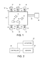
Fig. 1 is a schematical top view of a vehicle utilizing an embodiment of a center of gravity altering suspension system of the present invention; -
Fig. 2 is a block diagram of a control system utilized by the center of gravity altering suspension system ofFig. 1 ; and -
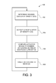
Fig. 3 is a flowchart of a method utilized by the control system ofFigs. 1 and 2 . - Corresponding reference characters indicate corresponding parts throughout the several views. The exemplification set out herein illustrates one embodiment of the invention and such exemplifications are not to be construed as limiting the scope of the invention in any manner.
- Referring now to the drawings, and more particularly to
Figs. 1 and 2 , there is illustrated avehicle 10 having achassis 12 with a center ofgravity 14 and a desired center ofgravity 16.Chassis 12 has groundengaging traction devices 18,suspension elements 20 andactuators 22.Sensors 24 are fixed aboutchassis 12 as well as onsuspension elements 20 to determine the position, attitude and orientation ofvehicle 10.Controller 26 is connected tosensors 24 as well asactuators 22 and based upon the input received fromsensors 24,controller 26 processes the information and actuatesactuators 22 to thereby carry out the method of the present invention. - An actuating
element 28 may be connected tochassis 12 with an acquiredload 30 being coupled thereto. This may be in the form of articulated arm or other device that is configured to engageload 30 and moveload 30 relative tochassis 12 and/or the ground. For example, actuating element: 28 may be the arm of a backhoe loader or a forestry vehicle. AlthoughFig. 1 illustrates a top view ofvehicle 10, it is also to be understood that center ofgravity vehicle 10 on the terrain. The desired center ofgravity 16 is illustrated as being in a different position than center ofgravity 14 to illustrate the method carried out incontroller 26. The desired center ofgravity 16 may be a predetermined center of gravity, or it may be a dynamically determined desired center ofgravity 16. For example, asload 30 is acquired the desired center ofgravity 16 may shift away fromload 30 to compensate for an additional potential load. In reaction to changes in the orientation ofvehicle 10 and loads applied thereto, center ofgravity 14 is calculated and the method of the present invention is carried out oncontroller 26 by the actuation ofactuators 22 which affectsuspension 20 so as to alter the calculated center ofgravity 14 such that it substantially corresponds with the desired center ofgravity 16. - Now, additionally referring to
Fig. 3 , there is illustrated an embodiment of the present invention in the form of amethod 100, which includessteps 102 through 108. Atstep 102method 100 determines the desired center ofgravity 16, which may be predetermined or a dynamically determine position. Atstep 104,method 100 detects the current center of gravity ofvehicle 10. Again this is a three-dimensional determination and the results are compared to the desired center ofgravity 16 in the actions to be undertaken instep 106. Instep 106,controller 26 computes what the needed movements ofactuators 22 are in order to minimize the difference between desired center ofgravity 16 and the calculated center ofgravity 14. Atstep 108,method 100 directsactuators 22 to activate and interact with elements ofsuspension 20 in order to shift the center ofgravity 14 toward the desiredserum gravity 16. -
Method 100 illustrates an advanced suspension system with an active CG management component. Active CG management involves tilting the chassis relative to the surface on which it is rested to optimally position the CG with respect to the support points, which in this case are ground engagingtraction devices 18, which may be in the form of wheels, on the terrain. In simple cases, with a properly balanced vehicle, this is essentially a self-leveling scheme. In more complex cases, the vehicle is able to use its own weight to counterbalance the terrain changes and to offset loads that may be placed uponchassis 12. - The
suspension 20 is either semi-active or fully active with passive elements to support the base load. The linkages ofsuspension 20 andactuators 22 have sufficient travel to permit moderate degrees of CG management while still isolatingvehicle 10 from terrain roughness. The present invention may shift between fully active suspension and semi-active suspension based on a trade-off between performance and energy requirements. A regenerative fully active system is contemplated with the regeneration occurring so that energy can be recaptured. Energy may be drawn from the power system, omitted for the sake of clarity, ofvehicle 10 to provide power and to enhance mobility ofvehicle 10.Vehicle 10 may be an unmanned guided vehicle (UGV) that actively controls the center of gravity. - Active center of gravity management entails lateral and longitudinal leveling of
chassis 12 by retracting highside suspension units 20 while simultaneously extending lowside suspension units 20.Controller 26 interacts with the plurality of ground engagingtraction devices 18 so as to conform with terrain curvature in both directions while simultaneously equalizing wheel loads to the extent allowed by the actual loading ofvehicle 10. Since total suspension travel is finite, the maximum leveling results in a relatively rigid suspension while operating on level train allows all of the suspension travel to be used to isolate the movements ofchassis 12 and the payload thereon from terrain-induced vibration. - When in fully active mode the suspension is most efficient when the dead load is supported by passive devices. The passive devices of the present invention allow for both static position adjustment and continuously variable spring rate. The advantages of these features are provided by the positioning of
actuators 22 and may include passive damping in a semi-active system using a minimum frequency response to allow for active CG management and a fully active version. The frequency response of the fully active suspension is adequate for center of gravity management and allows the static suspension adjustments to be made with a low-frequency system thereby reduce total energy requirements. - In contrast to prior art systems, the present invention, particularly for an unmanned vehicle, allows for the removal of human operator considerations with a corresponding loosening of limitations in the control the center of gravity. The use of semi-autonomous and autonomous vehicles allow many of the vehicle states to be measured and implemented, to also be used to perform vehicle guidance control as well. Exploiting the autonomous nature of the present invention and the subsequent knowledge of the vehicle states, the operational envelope of the vehicle's capability are enhanced by using the nonlinear suspension controller of the present invention.
Controller 26 has access to a memory device that contains constraints that are based on the material stress limits ofvehicle 10 and the electronics reliability factors such as those that are related to vibration. - The inputs to
controller 26 include feedback fromsensors 24 which include load sensors on each axle, wheel slip sensors, a vehicle speed sensor, a roll sensor, a pitch sensor and a yaw sensor. The sensors provide angle, angular rates and acceleration information tocontroller 26, with the information coming from an onboard inertial measurement unit (IMU). Additional inputs include vehicle vibration amplitude and frequency that is reported tocontroller 26 by way ofsensors 24. Based on the input information received bycontroller 26 anoptimal CG location 16 is determined atstep 102, with kinematic and dynamic constraints, and the errors between the current center ofgravity 14 and the desired center ofgravity 16 provide inputs to the nonlinear suspension control system of the present invention. - Further, positional detecting lasers such as scanning 3D SICK lasers, provide terrain mapping and perform predictive control of the center of gravity position. This allows for predictive control of the center of gravity based upon anticipated changes in the terrain.
- The nonlinear suspension system used by
controller 26 may be in the form of an optimal Mamdani type fuzzy system with some modifications to the rule base and the defuzzification method. The present invention controls the fluid flow to actuators 22 and act as a rate controller to remove saturation nonlinearity. As a rate controller,method 100 does not require rate of error changes as inputs. As there is no previous memory required by the present invention each controlled actuation will be a discrete event based upon the current state of the vehicle, thereby precluding a prior state input. - Due to the large number of inputs to
controller 26 and the need for a solution with a high degree of fidelity, an approach known as a fuzzy relations control strategy (FRCS) is employed to reduce the size of the rule base, while maintaining fidelity when beneficial. The FRCS method is a hierarchical method employed by the multi-objective nonlinear controller method implemented incontroller 26.Method 100 applies the control strategy in the following way: The linguistic variables for each membership function are termed the fuzzy relations control variables (FRCV). A multistage control strategy is defined using the fuzzy membership functions and their linguistic variables and is based on reducing the system error state or states to zero or as close to zero as possible. The related fuzzy relations control variables are used as classifiers within the rule-based structure, defining the relative importance of the other membership functions and maintaining the control strategy. Each fuzzy relations control variable has a corresponding degree of importance assigned thereto, based on the error state. - An issue avoided by the present invention is one that is reoccurring in prior art systems, relative to fuzzy controllers known as a "bang-bang" control effect. The definition of an acceptable region linguistic variables in all of the membership functions alleviates the bang-bang control effects as there is a specified state region on the system manifold where the vehicle state is acceptable (having reasonable error), with a corresponding crisp output of zero from
controller 26. Advantageously system response granularity is also reduced. - Whereas the system operates in real-time a center of maximum defuzzification method is utilized to provide crisp values to the valves associated with
actuators 22, to control the fluid flow to thesuspension actuators 22. Advantageously, the manipulating of the center of gravity placement allows for an operational envelope of the vehicle to be enhanced as well as extending the ability of the vehicle to operate in the most complex terrain. Movement ofactuators 22 can also be utilized to regenerate energy for storage in either pressurized hydraulic system or the charging of batteries.
Claims (10)
- A vehicle suspension control system, comprising:a plurality of ground engaging traction devices;a plurality of actuators, with at least one of said plurality of actuators correspondingly associated with each of said plurality of ground engaging traction devices;a plurality of sensors positioned about the vehicle; anda controller controllingly connected to each of said plurality of actuators, said controller receiving information from said plurality of sensors, said information relating to at least one of mass distributions of the vehicle and mass distributions of loads carried by the vehicle thereby defining distributed masses, said controller activating said plurality of actuators dependent upon said information and dependent upon a desired center of gravity of the vehicle to thereby alter a center of gravity of the vehicle, said controller computing what alteration of said actuators is needed to substantially reduce a value of a difference between said center of gravity of the vehicle and said desired center of gravity using a fuzzy relations control strategy.
- The vehicle of claim 1, wherein said fuzzy relations control strategy is a hierarchical method carried out on said controller.
- The vehicle of claim 2, wherein said controller is a multi-objective nonlinear controller.
- The vehicle of claim 1, wherein said fuzzy relations control strategy uses a reduced size rule base.
- The vehicle of claim 4, wherein said fuzzy relations control strategy includes minimizing system error states using fuzzy membership functions and linguistic variables.
- The vehicle of claim 5, wherein the linguistic variables are used as classifiers within a rule based structure to define a relative importance of the fuzzy membership functions.
- The vehicle of claim 6, wherein the linguistic variables each have a corresponding degree of importance assigned thereto, said degree of importance being dependent upon said error states.
- The vehicle of claim 1, wherein the vehicle is one of an agricultural vehicle, a construction vehicle, and a forestry vehicle.
- The vehicle of claim 1, wherein said fuzzy relations control strategy includes said activation of said actuators dependent on a current state of the vehicle.
- The vehicle of claim 9, wherein said fuzzy relations control strategy also includes said activation of said actuators being dependent on said current state of the vehicle without any prior state input.
Applications Claiming Priority (1)
| Application Number | Priority Date | Filing Date | Title |
|---|---|---|---|
| US13/192,900 US8825294B2 (en) | 2011-07-28 | 2011-07-28 | Vehicle center of gravity active suspension control system |
Publications (2)
| Publication Number | Publication Date |
|---|---|
| EP2551133A1 true EP2551133A1 (en) | 2013-01-30 |
| EP2551133B1 EP2551133B1 (en) | 2014-12-03 |
Family
ID=46395486
Family Applications (1)
| Application Number | Title | Priority Date | Filing Date |
|---|---|---|---|
| EP12173077.4A Not-in-force EP2551133B1 (en) | 2011-07-28 | 2012-06-22 | Active suspension system |
Country Status (2)
| Country | Link |
|---|---|
| US (1) | US8825294B2 (en) |
| EP (1) | EP2551133B1 (en) |
Cited By (1)
| Publication number | Priority date | Publication date | Assignee | Title |
|---|---|---|---|---|
| WO2020156816A1 (en) * | 2019-01-29 | 2020-08-06 | Volkswagen Aktiengesellschaft | Method and mobile transport device for transporting at least one item for transportation |
Families Citing this family (28)
| Publication number | Priority date | Publication date | Assignee | Title |
|---|---|---|---|---|
| EP2577027A2 (en) | 2010-06-03 | 2013-04-10 | Polaris Industries Inc. | Electronic throttle control |
| WO2013052540A2 (en) * | 2011-10-04 | 2013-04-11 | Parker-Hannifin Corporation | Method and system for controlling electric actuators |
| US9205717B2 (en) | 2012-11-07 | 2015-12-08 | Polaris Industries Inc. | Vehicle having suspension with continuous damping control |
| CA2890996C (en) | 2012-11-07 | 2023-03-21 | Polaris Industries Inc. | Vehicle having suspension with continuous damping control |
| JP5972941B2 (en) * | 2014-08-06 | 2016-08-17 | ファナック株式会社 | Machine tool with numerical controller |
| WO2016069405A2 (en) | 2014-10-31 | 2016-05-06 | Polaris Industries Inc. | System and method for controlling a vehicle |
| CN118849684A (en) | 2015-05-15 | 2024-10-29 | 北极星工业有限公司 | Multi-purpose vehicles |
| EP3303025B1 (en) * | 2015-06-03 | 2021-04-21 | Clearmotion, Inc. | Methods and systems for controlling vehicle body motion and occupant experience |
| US9963068B2 (en) | 2016-01-18 | 2018-05-08 | Toyota Motor Engineering & Manufacturing North America, Inc. | Vehicle proximity condition detection and haptic notification system |
| CA3043481C (en) | 2016-11-18 | 2022-07-26 | Polaris Industries Inc. | Vehicle having adjustable suspension |
| CN106909743B (en) * | 2017-03-02 | 2020-03-17 | 合肥工业大学 | Macpherson suspension hard point coordinate optimization method based on multi-target particle swarm optimization |
| US10406884B2 (en) | 2017-06-09 | 2019-09-10 | Polaris Industries Inc. | Adjustable vehicle suspension system |
| KR101859980B1 (en) * | 2017-12-13 | 2018-05-21 | 주식회사 뉴코애드윈드 | Device for controlling angle of truck load board using navigation system |
| US10946736B2 (en) | 2018-06-05 | 2021-03-16 | Polaris Industries Inc. | All-terrain vehicle |
| US10848090B2 (en) | 2018-06-28 | 2020-11-24 | Toyota Motor Engineering & Manufacturing North America, Inc. | Control methodology to reduce motor drive loss |
| US10987987B2 (en) | 2018-11-21 | 2021-04-27 | Polaris Industries Inc. | Vehicle having adjustable compression and rebound damping |
| CA3299418A1 (en) | 2019-04-30 | 2026-03-02 | Polaris Industries Inc. | Vehicle with removable final drive |
| US12016257B2 (en) | 2020-02-19 | 2024-06-25 | Sabanto, Inc. | Methods for detecting and clearing debris from planter gauge wheels, closing wheels and seed tubes |
| US11691674B2 (en) | 2020-05-15 | 2023-07-04 | Polaris Industries Inc. | Off-road vehicle |
| US12187127B2 (en) | 2020-05-15 | 2025-01-07 | Polaris Industries Inc. | Off-road vehicle |
| CN120735865A (en) | 2020-05-20 | 2025-10-03 | 北极星工业有限公司 | System and method for adjustable suspension for off-road recreational vehicle |
| MX2022015902A (en) | 2020-07-17 | 2023-01-24 | Polaris Inc | Adjustable suspensions and vehicle operation for off-road recreational vehicles. |
| US12461083B2 (en) | 2020-08-03 | 2025-11-04 | Sabanto, Inc. | Methods for improved agricultural procedures |
| MX2023006716A (en) | 2022-06-13 | 2023-12-14 | Polaris Inc | POWER TRAIN FOR UTILITY VEHICLE. |
| US11752882B1 (en) * | 2022-11-03 | 2023-09-12 | Ayro, Inc. | Systems and methods for controlling vehicle acceleration to regulate environmental impact |
| USD1067123S1 (en) | 2023-01-20 | 2025-03-18 | Polaris Industries Inc. | Off-road vehicle |
| USD1120805S1 (en) | 2023-06-29 | 2026-03-31 | Polaris Industries Inc. | Body assembly for an off-road vehicle |
| DE102023132647A1 (en) * | 2023-11-23 | 2025-05-28 | Zf Cv Systems Global Gmbh | Vehicle and method for controlling a vehicle |
Citations (6)
| Publication number | Priority date | Publication date | Assignee | Title |
|---|---|---|---|---|
| FR839855A (en) * | 1938-06-25 | 1939-04-13 | Motor car dynamic stabilization system | |
| US6424907B1 (en) * | 1998-07-17 | 2002-07-23 | Continental Teves Ag & Co., Ohg | Method and device for determining and detecting the overturning hazard of a vehicle |
| DE10306448A1 (en) * | 2003-02-17 | 2004-08-26 | Robert Bosch Gmbh | Anti-rollover device for countering the effect of a motor vehicle's rollover uses a centrifugal mass/balance weight sliding on a rail to alter the vehicle's point of gravity |
| US20060076741A1 (en) * | 2000-11-22 | 2006-04-13 | Lim Howard T S | Vehicle stability system: using active tilting mechanism as a counter measure to natural tilt |
| US20060265108A1 (en) * | 2003-07-11 | 2006-11-23 | Martin Kieren | Vehicle dynamics regulation system adapted to the rolling behaviour of a vehicle |
| US20080195282A1 (en) * | 2007-02-12 | 2008-08-14 | William Robert Norris | Perception model for trajectory following autonomous and human augmented steering control |
Family Cites Families (23)
| Publication number | Priority date | Publication date | Assignee | Title |
|---|---|---|---|---|
| JPH0741783B2 (en) * | 1986-05-23 | 1995-05-10 | 日産自動車株式会社 | Suspension controller |
| US5136513A (en) * | 1990-06-11 | 1992-08-04 | Ford Motor Company | Vehicle inertia and center of gravity estimator |
| US6463371B1 (en) * | 1998-10-22 | 2002-10-08 | Yamaha Hatsudoki Kabushiki Kaisha | System for intelligent control of a vehicle suspension based on soft computing |
| US7350787B2 (en) * | 2001-04-03 | 2008-04-01 | Voss Darrell W | Vehicles and methods using center of gravity and mass shift control system |
| US6701236B2 (en) * | 2001-10-19 | 2004-03-02 | Yamaha Hatsudoki Kabushiki Kaisha | Intelligent mechatronic control suspension system based on soft computing |
| US7219087B2 (en) * | 2003-07-25 | 2007-05-15 | Yamaha Hatsudoki Kabushiki Kaisha | Soft computing optimizer of intelligent control system structures |
| US7529609B2 (en) * | 2004-10-05 | 2009-05-05 | Vision Works Ip Corporation | Absolute acceleration sensor for use within moving vehicles |
| US7561951B2 (en) * | 2005-05-06 | 2009-07-14 | Ford Global Technologies Llc | Occupant control system integrated with vehicle dynamics controls |
| US20060293817A1 (en) * | 2005-06-23 | 2006-12-28 | Takahide Hagiwara | Intelligent electronically-controlled suspension system based on soft computing optimizer |
| US7694946B2 (en) | 2006-06-06 | 2010-04-13 | Deere & Company | Suspension system having active compensation for vibration |
| US7887033B2 (en) | 2006-06-06 | 2011-02-15 | Deere & Company | Suspension system having active compensation for vibration |
| JP2008024235A (en) * | 2006-07-24 | 2008-02-07 | Equos Research Co Ltd | vehicle |
| US7784570B2 (en) * | 2006-10-06 | 2010-08-31 | Irobot Corporation | Robotic vehicle |
| US7769512B2 (en) * | 2007-02-12 | 2010-08-03 | Deere & Company | Vehicle steering control method and performance |
| US8498796B2 (en) * | 2007-02-12 | 2013-07-30 | Deere & Company | Perception model for trajectory following autonomous and human augmented speed control |
| JP5013256B2 (en) * | 2007-08-07 | 2012-08-29 | 株式会社エクォス・リサーチ | vehicle |
| DE102007051262A1 (en) * | 2007-10-26 | 2009-07-16 | Wabco Gmbh | Device and method for automatic adjustment of the horizontal level of a commercial vehicle |
| SE532590C2 (en) * | 2007-11-09 | 2010-03-02 | Bae Systems Haegglunds Ab | Suspension device and method of suspension and / or damping of vehicles |
| JP4697254B2 (en) * | 2008-04-02 | 2011-06-08 | トヨタ自動車株式会社 | Vehicle behavior control device |
| JP5432688B2 (en) * | 2009-12-03 | 2014-03-05 | 株式会社日立製作所 | Mobile robot and its running stabilization method |
| US20110301785A1 (en) * | 2010-03-05 | 2011-12-08 | Sword Lee F | Biologically inspired compliant locomotion for remote vehicles |
| US20120158247A1 (en) * | 2010-12-15 | 2012-06-21 | William Robert Norris | Perception Model For Trajectory Following Autonomous And Human Augmented Steering Control |
| US8694207B2 (en) * | 2011-04-12 | 2014-04-08 | Robert Bosch Gmbh | Vehicle dynamic control systems with center of gravity compensation based on cargo information |
-
2011
- 2011-07-28 US US13/192,900 patent/US8825294B2/en active Active
-
2012
- 2012-06-22 EP EP12173077.4A patent/EP2551133B1/en not_active Not-in-force
Patent Citations (6)
| Publication number | Priority date | Publication date | Assignee | Title |
|---|---|---|---|---|
| FR839855A (en) * | 1938-06-25 | 1939-04-13 | Motor car dynamic stabilization system | |
| US6424907B1 (en) * | 1998-07-17 | 2002-07-23 | Continental Teves Ag & Co., Ohg | Method and device for determining and detecting the overturning hazard of a vehicle |
| US20060076741A1 (en) * | 2000-11-22 | 2006-04-13 | Lim Howard T S | Vehicle stability system: using active tilting mechanism as a counter measure to natural tilt |
| DE10306448A1 (en) * | 2003-02-17 | 2004-08-26 | Robert Bosch Gmbh | Anti-rollover device for countering the effect of a motor vehicle's rollover uses a centrifugal mass/balance weight sliding on a rail to alter the vehicle's point of gravity |
| US20060265108A1 (en) * | 2003-07-11 | 2006-11-23 | Martin Kieren | Vehicle dynamics regulation system adapted to the rolling behaviour of a vehicle |
| US20080195282A1 (en) * | 2007-02-12 | 2008-08-14 | William Robert Norris | Perception model for trajectory following autonomous and human augmented steering control |
Cited By (1)
| Publication number | Priority date | Publication date | Assignee | Title |
|---|---|---|---|---|
| WO2020156816A1 (en) * | 2019-01-29 | 2020-08-06 | Volkswagen Aktiengesellschaft | Method and mobile transport device for transporting at least one item for transportation |
Also Published As
| Publication number | Publication date |
|---|---|
| US8825294B2 (en) | 2014-09-02 |
| EP2551133B1 (en) | 2014-12-03 |
| US20130030650A1 (en) | 2013-01-31 |
Similar Documents
| Publication | Publication Date | Title |
|---|---|---|
| EP2551133B1 (en) | Active suspension system | |
| US12583440B2 (en) | Active safety suspension system | |
| CN110370877B (en) | Vehicle-mounted motion simulation platform based on active suspension and control method | |
| EP0114757B1 (en) | Vehicle suspension system | |
| US6684140B2 (en) | System for sensing vehicle global and relative attitudes using suspension height sensors | |
| CN101005981B (en) | Vehicle control device | |
| US10919520B1 (en) | Integrated chassis control | |
| EP1247665A1 (en) | Method and apparatus for controlling a vehicle suspension system based on sky hook approach | |
| CN108698464A (en) | System and method for the damper for controlling active suspension system | |
| CN115729098A (en) | Dynamically configured sideslip limit based vehicle control | |
| US20030205867A1 (en) | Suspension coordinator subsystem and method | |
| JP2007508185A (en) | Vehicle suspension control device | |
| EP1369288A2 (en) | A Method and System for Controlling a Motor Vehicle | |
| CN108357405B (en) | Semi-fixed surface | |
| EP1369284A2 (en) | A method and control system for a motor vehicle | |
| CN118119538A (en) | System and method for controlling the motion of a vehicle | |
| EP3995372A1 (en) | A method for controlling an actuator of a vehicle | |
| KR20240054985A (en) | Vehicle control for simplified autonomous driving | |
| CN114945809B (en) | Method for estimating tire normal force | |
| CN118850042A (en) | Vehicle control method and device and vehicle | |
| CN118323258A (en) | On-the-spot steering control method, device and vehicle based on driving intention | |
| CN105339196B (en) | For reducing the method for overturning risk for the motor vehicles for being provided with controllable suspension system | |
| CN121062694B (en) | Vehicle control method, device, computer device and storage medium | |
| US20180154731A1 (en) | Method and control device for adjusting the damping force of a shock absorber | |
| KR102643495B1 (en) | Active suspension control method of vehicle |
Legal Events
| Date | Code | Title | Description |
|---|---|---|---|
| PUAI | Public reference made under article 153(3) epc to a published international application that has entered the european phase |
Free format text: ORIGINAL CODE: 0009012 |
|
| AK | Designated contracting states |
Kind code of ref document: A1 Designated state(s): AL AT BE BG CH CY CZ DE DK EE ES FI FR GB GR HR HU IE IS IT LI LT LU LV MC MK MT NL NO PL PT RO RS SE SI SK SM TR |
|
| AX | Request for extension of the european patent |
Extension state: BA ME |
|
| 17P | Request for examination filed |
Effective date: 20130730 |
|
| RBV | Designated contracting states (corrected) |
Designated state(s): AL AT BE BG CH CY CZ DE DK EE ES FI FR GB GR HR HU IE IS IT LI LT LU LV MC MK MT NL NO PL PT RO RS SE SI SK SM TR |
|
| GRAP | Despatch of communication of intention to grant a patent |
Free format text: ORIGINAL CODE: EPIDOSNIGR1 |
|
| INTG | Intention to grant announced |
Effective date: 20140728 |
|
| GRAS | Grant fee paid |
Free format text: ORIGINAL CODE: EPIDOSNIGR3 |
|
| GRAA | (expected) grant |
Free format text: ORIGINAL CODE: 0009210 |
|
| AK | Designated contracting states |
Kind code of ref document: B1 Designated state(s): AL AT BE BG CH CY CZ DE DK EE ES FI FR GB GR HR HU IE IS IT LI LT LU LV MC MK MT NL NO PL PT RO RS SE SI SK SM TR |
|
| REG | Reference to a national code |
Ref country code: GB Ref legal event code: FG4D |
|
| REG | Reference to a national code |
Ref country code: AT Ref legal event code: REF Ref document number: 699146 Country of ref document: AT Kind code of ref document: T Effective date: 20141215 Ref country code: CH Ref legal event code: EP |
|
| REG | Reference to a national code |
Ref country code: IE Ref legal event code: FG4D |
|
| REG | Reference to a national code |
Ref country code: DE Ref legal event code: R096 Ref document number: 602012004064 Country of ref document: DE Effective date: 20150115 |
|
| REG | Reference to a national code |
Ref country code: NL Ref legal event code: VDEP Effective date: 20141203 |
|
| REG | Reference to a national code |
Ref country code: AT Ref legal event code: MK05 Ref document number: 699146 Country of ref document: AT Kind code of ref document: T Effective date: 20141203 |
|
| PG25 | Lapsed in a contracting state [announced via postgrant information from national office to epo] |
Ref country code: NL Free format text: LAPSE BECAUSE OF FAILURE TO SUBMIT A TRANSLATION OF THE DESCRIPTION OR TO PAY THE FEE WITHIN THE PRESCRIBED TIME-LIMIT Effective date: 20141203 Ref country code: ES Free format text: LAPSE BECAUSE OF FAILURE TO SUBMIT A TRANSLATION OF THE DESCRIPTION OR TO PAY THE FEE WITHIN THE PRESCRIBED TIME-LIMIT Effective date: 20141203 Ref country code: FI Free format text: LAPSE BECAUSE OF FAILURE TO SUBMIT A TRANSLATION OF THE DESCRIPTION OR TO PAY THE FEE WITHIN THE PRESCRIBED TIME-LIMIT Effective date: 20141203 Ref country code: LT Free format text: LAPSE BECAUSE OF FAILURE TO SUBMIT A TRANSLATION OF THE DESCRIPTION OR TO PAY THE FEE WITHIN THE PRESCRIBED TIME-LIMIT Effective date: 20141203 Ref country code: NO Free format text: LAPSE BECAUSE OF FAILURE TO SUBMIT A TRANSLATION OF THE DESCRIPTION OR TO PAY THE FEE WITHIN THE PRESCRIBED TIME-LIMIT Effective date: 20150303 |
|
| REG | Reference to a national code |
Ref country code: LT Ref legal event code: MG4D |
|
| PG25 | Lapsed in a contracting state [announced via postgrant information from national office to epo] |
Ref country code: RS Free format text: LAPSE BECAUSE OF FAILURE TO SUBMIT A TRANSLATION OF THE DESCRIPTION OR TO PAY THE FEE WITHIN THE PRESCRIBED TIME-LIMIT Effective date: 20141203 Ref country code: LV Free format text: LAPSE BECAUSE OF FAILURE TO SUBMIT A TRANSLATION OF THE DESCRIPTION OR TO PAY THE FEE WITHIN THE PRESCRIBED TIME-LIMIT Effective date: 20141203 Ref country code: SE Free format text: LAPSE BECAUSE OF FAILURE TO SUBMIT A TRANSLATION OF THE DESCRIPTION OR TO PAY THE FEE WITHIN THE PRESCRIBED TIME-LIMIT Effective date: 20141203 Ref country code: GR Free format text: LAPSE BECAUSE OF FAILURE TO SUBMIT A TRANSLATION OF THE DESCRIPTION OR TO PAY THE FEE WITHIN THE PRESCRIBED TIME-LIMIT Effective date: 20150304 Ref country code: HR Free format text: LAPSE BECAUSE OF FAILURE TO SUBMIT A TRANSLATION OF THE DESCRIPTION OR TO PAY THE FEE WITHIN THE PRESCRIBED TIME-LIMIT Effective date: 20141203 Ref country code: CY Free format text: LAPSE BECAUSE OF FAILURE TO SUBMIT A TRANSLATION OF THE DESCRIPTION OR TO PAY THE FEE WITHIN THE PRESCRIBED TIME-LIMIT Effective date: 20141203 Ref country code: AT Free format text: LAPSE BECAUSE OF FAILURE TO SUBMIT A TRANSLATION OF THE DESCRIPTION OR TO PAY THE FEE WITHIN THE PRESCRIBED TIME-LIMIT Effective date: 20141203 |
|
| PG25 | Lapsed in a contracting state [announced via postgrant information from national office to epo] |
Ref country code: SK Free format text: LAPSE BECAUSE OF FAILURE TO SUBMIT A TRANSLATION OF THE DESCRIPTION OR TO PAY THE FEE WITHIN THE PRESCRIBED TIME-LIMIT Effective date: 20141203 Ref country code: PT Free format text: LAPSE BECAUSE OF FAILURE TO SUBMIT A TRANSLATION OF THE DESCRIPTION OR TO PAY THE FEE WITHIN THE PRESCRIBED TIME-LIMIT Effective date: 20150403 Ref country code: EE Free format text: LAPSE BECAUSE OF FAILURE TO SUBMIT A TRANSLATION OF THE DESCRIPTION OR TO PAY THE FEE WITHIN THE PRESCRIBED TIME-LIMIT Effective date: 20141203 Ref country code: RO Free format text: LAPSE BECAUSE OF FAILURE TO SUBMIT A TRANSLATION OF THE DESCRIPTION OR TO PAY THE FEE WITHIN THE PRESCRIBED TIME-LIMIT Effective date: 20141203 Ref country code: CZ Free format text: LAPSE BECAUSE OF FAILURE TO SUBMIT A TRANSLATION OF THE DESCRIPTION OR TO PAY THE FEE WITHIN THE PRESCRIBED TIME-LIMIT Effective date: 20141203 |
|
| PG25 | Lapsed in a contracting state [announced via postgrant information from national office to epo] |
Ref country code: PL Free format text: LAPSE BECAUSE OF FAILURE TO SUBMIT A TRANSLATION OF THE DESCRIPTION OR TO PAY THE FEE WITHIN THE PRESCRIBED TIME-LIMIT Effective date: 20141203 Ref country code: IS Free format text: LAPSE BECAUSE OF FAILURE TO SUBMIT A TRANSLATION OF THE DESCRIPTION OR TO PAY THE FEE WITHIN THE PRESCRIBED TIME-LIMIT Effective date: 20150403 |
|
| REG | Reference to a national code |
Ref country code: DE Ref legal event code: R097 Ref document number: 602012004064 Country of ref document: DE |
|
| PLBE | No opposition filed within time limit |
Free format text: ORIGINAL CODE: 0009261 |
|
| STAA | Information on the status of an ep patent application or granted ep patent |
Free format text: STATUS: NO OPPOSITION FILED WITHIN TIME LIMIT |
|
| PG25 | Lapsed in a contracting state [announced via postgrant information from national office to epo] |
Ref country code: DK Free format text: LAPSE BECAUSE OF FAILURE TO SUBMIT A TRANSLATION OF THE DESCRIPTION OR TO PAY THE FEE WITHIN THE PRESCRIBED TIME-LIMIT Effective date: 20141203 |
|
| 26N | No opposition filed |
Effective date: 20150904 |
|
| PG25 | Lapsed in a contracting state [announced via postgrant information from national office to epo] |
Ref country code: IT Free format text: LAPSE BECAUSE OF FAILURE TO SUBMIT A TRANSLATION OF THE DESCRIPTION OR TO PAY THE FEE WITHIN THE PRESCRIBED TIME-LIMIT Effective date: 20141203 |
|
| PG25 | Lapsed in a contracting state [announced via postgrant information from national office to epo] |
Ref country code: MC Free format text: LAPSE BECAUSE OF FAILURE TO SUBMIT A TRANSLATION OF THE DESCRIPTION OR TO PAY THE FEE WITHIN THE PRESCRIBED TIME-LIMIT Effective date: 20141203 |
|
| REG | Reference to a national code |
Ref country code: CH Ref legal event code: PL |
|
| PG25 | Lapsed in a contracting state [announced via postgrant information from national office to epo] |
Ref country code: SI Free format text: LAPSE BECAUSE OF FAILURE TO SUBMIT A TRANSLATION OF THE DESCRIPTION OR TO PAY THE FEE WITHIN THE PRESCRIBED TIME-LIMIT Effective date: 20141203 Ref country code: LU Free format text: LAPSE BECAUSE OF FAILURE TO SUBMIT A TRANSLATION OF THE DESCRIPTION OR TO PAY THE FEE WITHIN THE PRESCRIBED TIME-LIMIT Effective date: 20150622 |
|
| REG | Reference to a national code |
Ref country code: IE Ref legal event code: MM4A |
|
| REG | Reference to a national code |
Ref country code: FR Ref legal event code: ST Effective date: 20160229 |
|
| PG25 | Lapsed in a contracting state [announced via postgrant information from national office to epo] |
Ref country code: LI Free format text: LAPSE BECAUSE OF NON-PAYMENT OF DUE FEES Effective date: 20150630 Ref country code: IE Free format text: LAPSE BECAUSE OF NON-PAYMENT OF DUE FEES Effective date: 20150622 Ref country code: CH Free format text: LAPSE BECAUSE OF NON-PAYMENT OF DUE FEES Effective date: 20150630 |
|
| PG25 | Lapsed in a contracting state [announced via postgrant information from national office to epo] |
Ref country code: BE Free format text: LAPSE BECAUSE OF FAILURE TO SUBMIT A TRANSLATION OF THE DESCRIPTION OR TO PAY THE FEE WITHIN THE PRESCRIBED TIME-LIMIT Effective date: 20141203 Ref country code: FR Free format text: LAPSE BECAUSE OF NON-PAYMENT OF DUE FEES Effective date: 20150630 |
|
| PG25 | Lapsed in a contracting state [announced via postgrant information from national office to epo] |
Ref country code: MT Free format text: LAPSE BECAUSE OF FAILURE TO SUBMIT A TRANSLATION OF THE DESCRIPTION OR TO PAY THE FEE WITHIN THE PRESCRIBED TIME-LIMIT Effective date: 20141203 |
|
| GBPC | Gb: european patent ceased through non-payment of renewal fee |
Effective date: 20160622 |
|
| PG25 | Lapsed in a contracting state [announced via postgrant information from national office to epo] |
Ref country code: GB Free format text: LAPSE BECAUSE OF NON-PAYMENT OF DUE FEES Effective date: 20160622 Ref country code: HU Free format text: LAPSE BECAUSE OF FAILURE TO SUBMIT A TRANSLATION OF THE DESCRIPTION OR TO PAY THE FEE WITHIN THE PRESCRIBED TIME-LIMIT; INVALID AB INITIO Effective date: 20120622 Ref country code: BG Free format text: LAPSE BECAUSE OF FAILURE TO SUBMIT A TRANSLATION OF THE DESCRIPTION OR TO PAY THE FEE WITHIN THE PRESCRIBED TIME-LIMIT Effective date: 20141203 Ref country code: SM Free format text: LAPSE BECAUSE OF FAILURE TO SUBMIT A TRANSLATION OF THE DESCRIPTION OR TO PAY THE FEE WITHIN THE PRESCRIBED TIME-LIMIT Effective date: 20141203 |
|
| PG25 | Lapsed in a contracting state [announced via postgrant information from national office to epo] |
Ref country code: TR Free format text: LAPSE BECAUSE OF FAILURE TO SUBMIT A TRANSLATION OF THE DESCRIPTION OR TO PAY THE FEE WITHIN THE PRESCRIBED TIME-LIMIT Effective date: 20141203 |
|
| PG25 | Lapsed in a contracting state [announced via postgrant information from national office to epo] |
Ref country code: MK Free format text: LAPSE BECAUSE OF FAILURE TO SUBMIT A TRANSLATION OF THE DESCRIPTION OR TO PAY THE FEE WITHIN THE PRESCRIBED TIME-LIMIT Effective date: 20141203 |
|
| PG25 | Lapsed in a contracting state [announced via postgrant information from national office to epo] |
Ref country code: AL Free format text: LAPSE BECAUSE OF FAILURE TO SUBMIT A TRANSLATION OF THE DESCRIPTION OR TO PAY THE FEE WITHIN THE PRESCRIBED TIME-LIMIT Effective date: 20141203 |
|
| PGFP | Annual fee paid to national office [announced via postgrant information from national office to epo] |
Ref country code: DE Payment date: 20240521 Year of fee payment: 13 |
|
| REG | Reference to a national code |
Ref country code: DE Ref legal event code: R119 Ref document number: 602012004064 Country of ref document: DE |
|
| PG25 | Lapsed in a contracting state [announced via postgrant information from national office to epo] |
Ref country code: DE Free format text: LAPSE BECAUSE OF NON-PAYMENT OF DUE FEES Effective date: 20260101 |