EP2551023A2 - Multi-nozzle spray gun - Google Patents
Multi-nozzle spray gun Download PDFInfo
- Publication number
- EP2551023A2 EP2551023A2 EP12177720A EP12177720A EP2551023A2 EP 2551023 A2 EP2551023 A2 EP 2551023A2 EP 12177720 A EP12177720 A EP 12177720A EP 12177720 A EP12177720 A EP 12177720A EP 2551023 A2 EP2551023 A2 EP 2551023A2
- Authority
- EP
- European Patent Office
- Prior art keywords
- nozzle
- region
- powder
- outlet
- axis
- Prior art date
- Legal status (The legal status is an assumption and is not a legal conclusion. Google has not performed a legal analysis and makes no representation as to the accuracy of the status listed.)
- Withdrawn
Links
- 0 CC1C(CCC2*3*C4C2CCCC(CC[Cn])CCCC(C)CC4C3)(CN*)C1 Chemical compound CC1C(CCC2*3*C4C2CCCC(CC[Cn])CCCC(C)CC4C3)(CN*)C1 0.000 description 1
Images





Classifications
-
- B—PERFORMING OPERATIONS; TRANSPORTING
- B05—SPRAYING OR ATOMISING IN GENERAL; APPLYING FLUENT MATERIALS TO SURFACES, IN GENERAL
- B05B—SPRAYING APPARATUS; ATOMISING APPARATUS; NOZZLES
- B05B7/00—Spraying apparatus for discharge of liquids or other fluent materials from two or more sources, e.g. of liquid and air, of powder and gas
- B05B7/14—Spraying apparatus for discharge of liquids or other fluent materials from two or more sources, e.g. of liquid and air, of powder and gas designed for spraying particulate materials
- B05B7/1481—Spray pistols or apparatus for discharging particulate material
- B05B7/1486—Spray pistols or apparatus for discharging particulate material for spraying particulate material in dry state
-
- B—PERFORMING OPERATIONS; TRANSPORTING
- B05—SPRAYING OR ATOMISING IN GENERAL; APPLYING FLUENT MATERIALS TO SURFACES, IN GENERAL
- B05B—SPRAYING APPARATUS; ATOMISING APPARATUS; NOZZLES
- B05B1/00—Nozzles, spray heads or other outlets, with or without auxiliary devices such as valves, heating means
- B05B1/14—Nozzles, spray heads or other outlets, with or without auxiliary devices such as valves, heating means with multiple outlet openings; with strainers in or outside the outlet opening
-
- B—PERFORMING OPERATIONS; TRANSPORTING
- B05—SPRAYING OR ATOMISING IN GENERAL; APPLYING FLUENT MATERIALS TO SURFACES, IN GENERAL
- B05B—SPRAYING APPARATUS; ATOMISING APPARATUS; NOZZLES
- B05B7/00—Spraying apparatus for discharge of liquids or other fluent materials from two or more sources, e.g. of liquid and air, of powder and gas
- B05B7/02—Spray pistols; Apparatus for discharge
- B05B7/08—Spray pistols; Apparatus for discharge with separate outlet orifices, e.g. to form parallel jets, i.e. the axis of the jets being parallel, to form intersecting jets, i.e. the axis of the jets converging but not necessarily intersecting at a point
- B05B7/0807—Spray pistols; Apparatus for discharge with separate outlet orifices, e.g. to form parallel jets, i.e. the axis of the jets being parallel, to form intersecting jets, i.e. the axis of the jets converging but not necessarily intersecting at a point to form intersecting jets
-
- C—CHEMISTRY; METALLURGY
- C23—COATING METALLIC MATERIAL; COATING MATERIAL WITH METALLIC MATERIAL; CHEMICAL SURFACE TREATMENT; DIFFUSION TREATMENT OF METALLIC MATERIAL; COATING BY VACUUM EVAPORATION, BY SPUTTERING, BY ION IMPLANTATION OR BY CHEMICAL VAPOUR DEPOSITION, IN GENERAL; INHIBITING CORROSION OF METALLIC MATERIAL OR INCRUSTATION IN GENERAL
- C23C—COATING METALLIC MATERIAL; COATING MATERIAL WITH METALLIC MATERIAL; SURFACE TREATMENT OF METALLIC MATERIAL BY DIFFUSION INTO THE SURFACE, BY CHEMICAL CONVERSION OR SUBSTITUTION; COATING BY VACUUM EVAPORATION, BY SPUTTERING, BY ION IMPLANTATION OR BY CHEMICAL VAPOUR DEPOSITION, IN GENERAL
- C23C24/00—Coating starting from inorganic powder
- C23C24/02—Coating starting from inorganic powder by application of pressure only
- C23C24/04—Impact or kinetic deposition of particles
-
- B—PERFORMING OPERATIONS; TRANSPORTING
- B05—SPRAYING OR ATOMISING IN GENERAL; APPLYING FLUENT MATERIALS TO SURFACES, IN GENERAL
- B05B—SPRAYING APPARATUS; ATOMISING APPARATUS; NOZZLES
- B05B13/00—Machines or plants for applying liquids or other fluent materials to surfaces of objects or other work by spraying, not covered by groups B05B1/00 - B05B11/00
- B05B13/02—Means for supporting work; Arrangement or mounting of spray heads; Adaptation or arrangement of means for feeding work
- B05B13/04—Means for supporting work; Arrangement or mounting of spray heads; Adaptation or arrangement of means for feeding work the spray heads being moved during spraying operation
- B05B13/0431—Means for supporting work; Arrangement or mounting of spray heads; Adaptation or arrangement of means for feeding work the spray heads being moved during spraying operation with spray heads moved by robots or articulated arms, e.g. for applying liquid or other fluent material to three-dimensional [3D] surfaces
Definitions
- the subject matter disclosed herein relates to the art of spraying and, more particularly, to a spray gun having multiple independently controllable nozzles.
- spray techniques are generally used to provide a surface treatment to a component.
- Cold spray techniques for example, are employed when it is desired to apply a coating without adding heat or the like to affect a bond between the component to be coated and a coating material.
- Other applications for cold spraying include constructing free-form structures.
- Cold spray techniques utilize a cold spray gun that delivers particles onto a surface at high velocity.
- the particular velocity used is generally dependent upon the particles being sprayed.
- Harder particles require spraying at higher velocities to ensure adhesion while lower velocities may be acceptable to facilitate adhesion of softer particles.
- soft and hard particles required different velocities, cold spraying composite materials presents various challenges.
- a first layer is formed by applying either hard or soft particles. After applying the first layer, a second layer including the other of the hard and soft particles is applied.
- hard and soft particles are mixed to form a composite mixture that is delivered into a surface.
- An application velocity for the composite material is chosen that facilitates adhesion of the harder particles without causing damage to the softer particles. Often times, establishing a velocity that achieves both goals is not possible.
- a spray apparatus includes a body having an outer surface and an interior portion, and a first nozzle arranged in the interior portion of the body.
- the first nozzle includes a first material inlet member and a first convergent region, a first throat region, a first divergent region, and a first outlet.
- the first throat region and first outlet establish a first expansion ratio.
- a second nozzle is arranged in the interior portion of the body adjacent the first nozzle.
- the second nozzle includes a second material inlet member and a second convergent region, a second throat region, a second divergent region, and a second outlet.
- the second throat region and the second outlet establish a second expansion ratio that is distinct from the first expansion ratio.
- a method of spraying a composite layer onto a substrate includes discharging a first material from a first nozzle in a spray gun at a first velocity, and discharging a second material from a second nozzle in the spray gun at a second velocity distinct from the first velocity.
- spray apparatus comprises a cold spray apparatus for spraying cold spray powders.
- spray apparatus 2 could be employed to discharge a variety of materials.
- Spray apparatus 2 includes a multi-nozzle cold spray gun 8 mounted to a robot arm 9.
- multi-nozzle cold spray gun 8 could also be hand held or manipulated by various other devices.
- Multi-nozzle cold spray gun 8 includes a head portion 10 having an outlet 11 and is operatively connected to a gas heater 12 including a powder hopper 13.
- powder hopper 13 could be a separate unit from gas heater 12.
- Gas heater 12 receives a supply of gas from a gas control module 14 via a hose 15.
- a portion of the supply of gas from gas control module 14 is diverted to powder hopper 13 to serve as a carrier for the powder.
- the gas and powder is then directed to multi-nozzle cold spray gun 8 via a process gas supply hose 16 and a powder supply hose 17.
- Process gas supply hose 16 delivers gas to multi-nozzle cold spray gun 8 while powder supply hose 17 delivers powder from powder hopper 13.
- the gas and powder pass from multi-nozzle cold spray gun 8 onto a component (not shown) to form a coating.
- powder hopper 13 may supply a number of different powder types to multi-nozzle cold spray gun 8 to be delivered onto the component.
- powder supply hose 17 may comprise multiple internal passages (not shown), may comprise multiple powder supply hoses (also not shown), or multiple powder hoppers coupled to multiple distinct hoses (not shown).
- head portion 10 includes a body 23 having an interior portion 25 within which are arranged multiple, independently fed nozzles 30-34 that are arranged along respective parallel axes 36-40.
- Nozzles 30-34 accelerate the gas and powder for delivery onto a substrate (not shown).
- the gas forces the powder onto the substrate at speeds, typically in a range of between 800 m/s to 1500 m/s.
- the high speed delivery causes the powder to adhere to the component and form a coating.
- delivery speeds can vary to levels below 800 m/s and above 1500 m/s depending on desired adhesion characteristics and powder type.
- powder discharge velocity for each nozzle 30-34 could vary.
- each nozzle 30-34 is substantially similar, a detailed description will follow to FIGS. 3 and 4 in describing nozzles 30 and 31 with an understanding that nozzles 32 and 33 include corresponding structure. It should however be understood that each nozzle 30-34 can have a different geometry depending upon various parameters such as process gas type, powder type, and the like.
- nozzle 30 includes a nozzle body 47 having an inlet region 51, a convergent region 53, a throat region 55, and a divergent region 57 having an outlet 58.
- Inlet region 51 includes a process gas inlet 62, a sensor receiver 64, and a powder inlet 67.
- Process gas inlet 62 is configured to receive process gas from process gas supply hose 16.
- Sensor receiver 64 supports temperature and/or pressure sensors configured to monitor parameters of the process gas.
- Powder inlet 67 includes an inlet member 69 that is configured to receive powder through powder supply hose 17, and an outlet member 71 that delivers gas and powder toward outlet 58.
- outlet member 71 is arranged upstream from convergent region 53 and includes a powder outlet 74 and a plurality of gas outlets, one of which is indicated at 77.
- the process gas serves as a carrier that delivers the powder onto a substrate with the particular geometry of nozzle 30 creating a desired acceleration of the process gas and powder.
- the throat region 55 and outlet 58 establish a particular expansion ratio for nozzle 30 that can be tailored to establish an application velocity associated with particular material properties and based on a desired gas or powder discharge velocity for a desired application.
- the expansion ratio is defined as a ratio between a cross-sectional area of outlet 58 and throat region 55 as described by the equation below:
- a A * 1 M ⁇ 2 ⁇ + 1 ⁇ 1 + ⁇ - 1 2 ⁇ M 2 ⁇ + 1 2 ⁇ ⁇ - 1
- A is the area of outlet 58 and A * is the area of throat region 55.
- Gamma is the ratio C p /C v of the process gas being used.
- M is the Mach number predicted by the equation.
- nozzle 31 includes a nozzle body 86 having an inlet region 88, a convergent region 90, a throat region 92, and a divergent region 94 having an outlet 95.
- Inlet region 88 includes a process gas inlet 97, a sensor receiver 99, and a powder inlet 101.
- process gas inlet 97 is configured to receive process gas from process gas supply hose 16.
- Sensor receiver 99 supports temperature and/or pressure sensors configured to monitor parameters of the process gas.
- Powder inlet 101 includes an inlet member 104 that is configured to receive powder through powder supply hose 17, and an outlet member 106 that delivers gas and powder toward outlet 58.
- Powder inlet 101 can receive a powder similar to that supplied to nozzle 30 or an entirely different powder depending upon desired coating characteristics. That is, one of nozzles 30-34 can direct a hard powder onto a substrate and another of nozzles 30-34 can direct a softer powder onto a substrate.
- outlet member 106 is arranged upstream from convergent region 90 and includes a powder outlet 108 and a plurality of gas outlets, one of which is indicated at 110.
- throat region 55 and outlet 58 establish a particular expansion ratio for nozzle 31 that can be tailored to particular parameters based on a desired powder output speed for a desired application.
- the expansion ration for each nozzle 30-34 can be the same or different depending upon desired powder application parameters.
- cold spray gun 8 can create a multi-component powder mix that is delivered onto a substrate without the need for multiple distinct applications or tailoring application parameters to accommodate two different powders.
- each nozzle 30-34 can be independently tailored for a particular gas/powder combination. That is, powder/gas streams from each nozzle 30-34 may be at similar or different/distinct velocities depending upon application parameters associated with powder being employed and/or the substrate being coated.
- Nozzle 120 can replace one or more of, and/or augment, nozzles 30-34 depending upon desired application parameters.
- Nozzle 120 includes a nozzle body 124 having an inlet region 126, a convergent region 128, a throat region 130, a substantially straight region 132, and a divergent region 134 having an outlet 135.
- substantially straight region 132 is positioned between throat region 130 and divergent region 134.
- Inlet region 126 includes a process gas inlet 137, a sensor receiver 139, and a powder inlet 141.
- process gas inlet 137 is configured to receive process gas from process gas supply hose 16.
- Sensor receiver 139 supports temperature and/or pressure sensors configured to monitor parameters of the process gas.
- Powder inlet 141 includes an inlet member 143 that is configured to receive powder through powder supply hose 17, and an outlet member 145 that delivers gas and powder toward outlet 135.
- Outlet member 145 includes a powder outlet 147 and a plurality of gas outlets, one of which is indicated at 149.
- Nozzle 160 can replace one or more of, and/or augment, nozzles 30-34 depending upon desired application parameters.
- Nozzle 160 includes a nozzle body 162 having an inlet region 165, a convergent region 167, a throat region 169, a divergent region 171, and a substantially straight region 173 having an outlet 175.
- substantially straight region 173 is positioned downstream from divergent region 171.
- Inlet region 165 includes a process gas inlet 177, a sensor receiver 179, and a powder inlet 181.
- process gas inlet 177 is configured to receive process gas from process gas supply hose 16.
- Sensor receiver 179 supports temperature and/or pressure sensors configured to monitor parameters of the process gas.
- Powder inlet 181 includes an inlet member 183 that is configured to receive powder through powder supply hose 17, and an outlet member 185 that delivers gas and powder toward outlet 175.
- Outlet member 185 includes a powder outlet 187 and a plurality of gas outlets, one of which is indicated at 189.
- Nozzle 200 can replace one or more of, and/or augment, nozzles 30-34 depending upon desired application parameters.
- Nozzle 200 includes a nozzle body 202 having an inlet region 205, a convergent region 207, a throat region 210, and a divergent region 213 having an outlet 214.
- Inlet region 205 includes a process gas inlet 216, a sensor receiver 219, and a powder inlet 221.
- process gas inlet 216 is configured to receive process gas from process gas supply hose 16.
- Sensor receiver 219 supports temperature and/or pressure sensors configured to monitor parameters of the process gas.
- Powder inlet 221 includes an inlet member 223 that is configured to receive powder through powder supply hose 17, and an outlet member 225 that delivers gas and powder toward outlet 214.
- outlet member 225 is arranged within convergent region 207 and includes a powder outlet 226 and a gas outlet 228. The particular location of outlet member 225 within convergent region 207 can vary and provides a particular acceleration of the gas and powder to establish a desired application parameter.
- Nozzle 232 can replace one or more of, and/or augment, nozzles 30-34 depending upon desired application parameters.
- Nozzle 232 includes a nozzle body 234 having an inlet region 236, a convergent region 238, a throat region 240, and a divergent region 242 having an outlet 243.
- Inlet region 236 includes a process gas inlet 245, a sensor receiver 246, and a powder inlet 248.
- process gas inlet 245 is configured to receive process gas from process gas supply hose 16.
- Sensor receiver 246 supports temperature and/or pressure sensors configured to monitor parameters of the process gas.
- Powder inlet 248 includes an inlet member 249 that is configured to receive powder through powder supply hose 17, and an outlet member 250 that delivers gas and powder toward outlet 243.
- outlet member 250 is arranged within throat region 240 and includes a powder outlet 252 and a gas outlet 254. The particular location of outlet member 250 within throat region 240 provides a particular acceleration of the gas and powder to establish a desired application parameter.
- Head portion 260 includes a body 264 having an outlet 267.
- Body 264 includes an interior portion 265 within which are arranged a plurality of nozzles 270-274.
- Nozzles 270-274 extend along axes 280-284 that are angled relative to head portion 260. More specifically, axes 280-284 are angled such that powder/gas steams from each nozzle 270-274 converge at a focal point (not shown) downstream from outlet 267. With this arrangement, multiple streams of gas/powder are directed toward a single point on a substrate.
- Head portion 300 includes a body 304 having an outlet 307.
- Body 304 includes an interior portion 306 within which are arranged a plurality of independent micro-nozzles 310-322.
- Micro-nozzles 310-322 can be arranged along parallel axes or converging axes depending upon a desired application.
- Micro-nozzles 310-322 deliver multiple gas/powder streams onto a substrate.
- Each micro-nozzle can be configured to pass a similar powder or different powders having similar or different properties such as hardness, composition, morphology, and particle size depending upon the coating desired.
- Spray parameters like powder feed rate, gas flow, pressure and temperature, type of gas (i.e. helium, nitrogen, air or mixes thereof) can be independently controlled for each nozzle through the controller. More specifically, the present invention describes multiple spray guns that may have distinct designs and which are selectively independently controlled.
- the exemplary embodiments describe a spray gun having multiple independently controllable nozzles that can be configured to deliver similar or distinct materials onto a substrate.
- Each nozzle may be configured to have a particular expansion ratio to create a desired material application velocity.
- a material introduction point for each nozzle can be tailored to further establish a particular material application velocity. That is, the material may be introduced at a point that is upstream of the convergent region to a point that is within the divergent region to discharge velocity to a desired parameter.
- the number, type, and angle of the nozzles can vary.
- the cold spray gun could also be configured to include both parallel and converging nozzles.
- other materials including both solids and liquids may be passed through the spray apparatus in accordance with the exemplary embodiment.
Landscapes
- Chemical & Material Sciences (AREA)
- Chemical Kinetics & Catalysis (AREA)
- Engineering & Computer Science (AREA)
- Materials Engineering (AREA)
- Mechanical Engineering (AREA)
- Metallurgy (AREA)
- Organic Chemistry (AREA)
- Nozzles (AREA)
Abstract
A spray apparatus includes a body having an outer surface and an interior portion, and a first nozzle (30) arranged in the interior portion of the body. The first nozzle (30) includes a first material inlet, a first convergent region (53), a first throat region (55), a first divergent region (57), and a first outlet (10). The first throat region (55) and first outlet (10) establish a first expansion ratio. A second nozzle is arranged in the interior portion of the body adjacent the first nozzle (30). The second nozzle (31) includes a second material inlet, a second convergent region, a second throat region (92), a second divergent region, and a second outlet. The second throat region (92) and the second outlet establish a second expansion ratio that is distinct from the first expansion ratio.
Description
- The subject matter disclosed herein relates to the art of spraying and, more particularly, to a spray gun having multiple independently controllable nozzles.
- Conventionally, spray techniques are generally used to provide a surface treatment to a component. Cold spray techniques, for example, are employed when it is desired to apply a coating without adding heat or the like to affect a bond between the component to be coated and a coating material. Other applications for cold spraying include constructing free-form structures.
- Cold spray techniques utilize a cold spray gun that delivers particles onto a surface at high velocity. The particular velocity used is generally dependent upon the particles being sprayed. Harder particles require spraying at higher velocities to ensure adhesion while lower velocities may be acceptable to facilitate adhesion of softer particles. As soft and hard particles required different velocities, cold spraying composite materials presents various challenges. Currently, there are two techniques for achieving a cold sprayed coating formed from hard and soft particles. In one technique, a first layer is formed by applying either hard or soft particles. After applying the first layer, a second layer including the other of the hard and soft particles is applied. In another technique, hard and soft particles are mixed to form a composite mixture that is delivered into a surface. An application velocity for the composite material is chosen that facilitates adhesion of the harder particles without causing damage to the softer particles. Often times, establishing a velocity that achieves both goals is not possible.
- According to one aspect of the invention, a spray apparatus includes a body having an outer surface and an interior portion, and a first nozzle arranged in the interior portion of the body. The first nozzle includes a first material inlet member and a first convergent region, a first throat region, a first divergent region, and a first outlet. The first throat region and first outlet establish a first expansion ratio. A second nozzle is arranged in the interior portion of the body adjacent the first nozzle. The second nozzle includes a second material inlet member and a second convergent region, a second throat region, a second divergent region, and a second outlet. The second throat region and the second outlet establish a second expansion ratio that is distinct from the first expansion ratio.
- According to another aspect of the invention, a method of spraying a composite layer onto a substrate includes discharging a first material from a first nozzle in a spray gun at a first velocity, and discharging a second material from a second nozzle in the spray gun at a second velocity distinct from the first velocity.
- These and other advantages and features will become more apparent from the following description taken in conjunction with the drawings.
- Embodiments of the present invention will now be described, by way of example only, with reference to the accompanying drawings in which:
-
FIG. 1 is a perspective view of a spray apparatus including a multi-nozzle cold spray gun in accordance with an exemplary embodiment; -
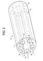
FIG. 2 is a partial perspective view of a head portion of the multi-nozzle cold spray gun ofFIG. 1 in accordance with one aspect of the exemplary embodiment; -
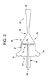
FIG. 3 is a cross-sectional view of one nozzle of the multi-nozzle cold spray gun ofFIG. 1 ; -
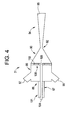
FIG. 4 is a cross-sectional view of another nozzle of the multi-nozzle cold spray gun ofFIG. 1 ; -
FIG. 5 is a cross-sectional view of a nozzle of the multi-nozzle cold spray gun ofFIG. 1 in accordance with another aspect of the exemplary embodiment; -
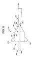
FIG. 6 is a cross-sectional view of a nozzle of the multi-nozzle cold spray gun ofFIG. 1 in accordance with yet another aspect of the exemplary embodiment; -
FIG. 7 is a cross-sectional view of a nozzle of the multi-nozzle cold spray gun ofFIG. 1 in accordance with still another aspect of the exemplary embodiment; -
FIG. 8 is a cross-sectional view of a nozzle of the multi-nozzle cold spray gun ofFIG. 1 in accordance with still yet another aspect of the exemplary embodiment; -
FIG. 9 is a partial perspective view of a head portion of the multi-nozzle cold spray gun ofFIG. 1 in accordance with another aspect of the exemplary embodiment; and -
FIG. 10 is a partial perspective view of a head portion of the multi-nozzle cold spray gun ofFIG. 1 in accordance with yet another aspect of the exemplary embodiment. - The detailed description explains embodiments of the invention, together with advantages and features, by way of example with reference to the drawings.
- With initial reference to
FIG. 1 , a spray apparatus is indicated generally at 2. In the exemplary embodiment shown, spray apparatus comprises a cold spray apparatus for spraying cold spray powders. However, it should be understood that spray apparatus 2 could be employed to discharge a variety of materials. Spray apparatus 2 includes a multi-nozzle cold spray gun 8 mounted to arobot arm 9. Of course, multi-nozzle cold spray gun 8 could also be hand held or manipulated by various other devices. Multi-nozzle cold spray gun 8 includes ahead portion 10 having anoutlet 11 and is operatively connected to agas heater 12 including apowder hopper 13. Of course it should be understood thatpowder hopper 13 could be a separate unit fromgas heater 12.Gas heater 12 receives a supply of gas from agas control module 14 via ahose 15. A portion of the supply of gas fromgas control module 14 is diverted topowder hopper 13 to serve as a carrier for the powder. The gas and powder is then directed to multi-nozzle cold spray gun 8 via a processgas supply hose 16 and apowder supply hose 17. Processgas supply hose 16 delivers gas to multi-nozzle cold spray gun 8 whilepowder supply hose 17 delivers powder frompowder hopper 13. The gas and powder pass from multi-nozzle cold spray gun 8 onto a component (not shown) to form a coating. As will become more fully evident below,powder hopper 13 may supply a number of different powder types to multi-nozzle cold spray gun 8 to be delivered onto the component. Thus,powder supply hose 17 may comprise multiple internal passages (not shown), may comprise multiple powder supply hoses (also not shown), or multiple powder hoppers coupled to multiple distinct hoses (not shown). - As best shown in
FIG. 2 ,head portion 10 includes abody 23 having aninterior portion 25 within which are arranged multiple, independently fed nozzles 30-34 that are arranged along respective parallel axes 36-40. Nozzles 30-34 accelerate the gas and powder for delivery onto a substrate (not shown). The gas forces the powder onto the substrate at speeds, typically in a range of between 800 m/s to 1500 m/s. The high speed delivery causes the powder to adhere to the component and form a coating. Of course it should be understood that delivery speeds can vary to levels below 800 m/s and above 1500 m/s depending on desired adhesion characteristics and powder type. It should also be understood that powder discharge velocity for each nozzle 30-34 could vary. As each nozzle 30-34 is substantially similar, a detailed description will follow toFIGS. 3 and4 in describingnozzles nozzles - In accordance with an exemplary embodiment,
nozzle 30 includes anozzle body 47 having aninlet region 51, aconvergent region 53, athroat region 55, and adivergent region 57 having anoutlet 58.Inlet region 51 includes aprocess gas inlet 62, asensor receiver 64, and apowder inlet 67.Process gas inlet 62 is configured to receive process gas from processgas supply hose 16.Sensor receiver 64 supports temperature and/or pressure sensors configured to monitor parameters of the process gas.Powder inlet 67 includes aninlet member 69 that is configured to receive powder throughpowder supply hose 17, and anoutlet member 71 that delivers gas and powder towardoutlet 58. - In the exemplary embodiment shown,
outlet member 71 is arranged upstream fromconvergent region 53 and includes apowder outlet 74 and a plurality of gas outlets, one of which is indicated at 77. Of course, a single outlet may also be employed. The process gas serves as a carrier that delivers the powder onto a substrate with the particular geometry ofnozzle 30 creating a desired acceleration of the process gas and powder. More specifically, thethroat region 55 andoutlet 58 establish a particular expansion ratio fornozzle 30 that can be tailored to establish an application velocity associated with particular material properties and based on a desired gas or powder discharge velocity for a desired application. The expansion ratio is defined as a ratio between a cross-sectional area ofoutlet 58 andthroat region 55 as described by the equation below:
- Where A is the area of
outlet 58 and A* is the area ofthroat region 55. Gamma is the ratio Cp/Cv of the process gas being used. M is the Mach number predicted by the equation. - Similarly,
nozzle 31 includes anozzle body 86 having an inlet region 88, aconvergent region 90, athroat region 92, and adivergent region 94 having anoutlet 95. Inlet region 88 includes aprocess gas inlet 97, asensor receiver 99, and apowder inlet 101. In a manner similar to that described above,process gas inlet 97 is configured to receive process gas from processgas supply hose 16.Sensor receiver 99 supports temperature and/or pressure sensors configured to monitor parameters of the process gas.Powder inlet 101 includes aninlet member 104 that is configured to receive powder throughpowder supply hose 17, and anoutlet member 106 that delivers gas and powder towardoutlet 58. -
Powder inlet 101 can receive a powder similar to that supplied tonozzle 30 or an entirely different powder depending upon desired coating characteristics. That is, one of nozzles 30-34 can direct a hard powder onto a substrate and another of nozzles 30-34 can direct a softer powder onto a substrate. In the exemplary embodiment shown,outlet member 106 is arranged upstream fromconvergent region 90 and includes apowder outlet 108 and a plurality of gas outlets, one of which is indicated at 110. In a manner similar to that described above,throat region 55 andoutlet 58 establish a particular expansion ratio fornozzle 31 that can be tailored to particular parameters based on a desired powder output speed for a desired application. Thus, the expansion ration for each nozzle 30-34 can be the same or different depending upon desired powder application parameters. - With this arrangement, cold spray gun 8 can create a multi-component powder mix that is delivered onto a substrate without the need for multiple distinct applications or tailoring application parameters to accommodate two different powders. In accordance with the exemplary embodiment, each nozzle 30-34 can be independently tailored for a particular gas/powder combination. That is, powder/gas streams from each nozzle 30-34 may be at similar or different/distinct velocities depending upon application parameters associated with powder being employed and/or the substrate being coated.
- Reference will now be made to
FIG. 5 in describing anozzle 120 in accordance with another aspect of the exemplary embodiment.Nozzle 120 can replace one or more of, and/or augment, nozzles 30-34 depending upon desired application parameters.Nozzle 120 includes anozzle body 124 having aninlet region 126, aconvergent region 128, athroat region 130, a substantiallystraight region 132, and adivergent region 134 having anoutlet 135. In the exemplary embodiment shown, substantiallystraight region 132 is positioned betweenthroat region 130 anddivergent region 134.Inlet region 126 includes aprocess gas inlet 137, asensor receiver 139, and apowder inlet 141. As discussed above,process gas inlet 137 is configured to receive process gas from processgas supply hose 16.Sensor receiver 139 supports temperature and/or pressure sensors configured to monitor parameters of the process gas.Powder inlet 141 includes aninlet member 143 that is configured to receive powder throughpowder supply hose 17, and anoutlet member 145 that delivers gas and powder towardoutlet 135.Outlet member 145 includes apowder outlet 147 and a plurality of gas outlets, one of which is indicated at 149. - Reference will now be made to
FIG. 6 in describing anozzle 160 in accordance with another aspect of the exemplary embodiment. In a manner similar to that discussed above,nozzle 160 can replace one or more of, and/or augment, nozzles 30-34 depending upon desired application parameters.Nozzle 160 includes anozzle body 162 having aninlet region 165, aconvergent region 167, athroat region 169, adivergent region 171, and a substantiallystraight region 173 having anoutlet 175. In the exemplary embodiment shown, substantiallystraight region 173 is positioned downstream fromdivergent region 171.Inlet region 165 includes aprocess gas inlet 177, asensor receiver 179, and apowder inlet 181. As discussed above,process gas inlet 177 is configured to receive process gas from processgas supply hose 16.Sensor receiver 179 supports temperature and/or pressure sensors configured to monitor parameters of the process gas.Powder inlet 181 includes aninlet member 183 that is configured to receive powder throughpowder supply hose 17, and anoutlet member 185 that delivers gas and powder towardoutlet 175.Outlet member 185 includes apowder outlet 187 and a plurality of gas outlets, one of which is indicated at 189. - Reference will now be made to
FIG. 7 in describing anozzle 200 in accordance with another aspect of the exemplary embodiment. In a manner also similar to that discussed above,nozzle 200 can replace one or more of, and/or augment, nozzles 30-34 depending upon desired application parameters.Nozzle 200 includes anozzle body 202 having aninlet region 205, aconvergent region 207, athroat region 210, and adivergent region 213 having anoutlet 214.Inlet region 205 includes aprocess gas inlet 216, asensor receiver 219, and apowder inlet 221. As discussed above,process gas inlet 216 is configured to receive process gas from processgas supply hose 16.Sensor receiver 219 supports temperature and/or pressure sensors configured to monitor parameters of the process gas.Powder inlet 221 includes aninlet member 223 that is configured to receive powder throughpowder supply hose 17, and anoutlet member 225 that delivers gas and powder towardoutlet 214. In accordance with the exemplary embodiment,outlet member 225 is arranged withinconvergent region 207 and includes apowder outlet 226 and agas outlet 228. The particular location ofoutlet member 225 withinconvergent region 207 can vary and provides a particular acceleration of the gas and powder to establish a desired application parameter. - Reference will now be made to
FIG. 8 in describing anozzle 232 in accordance with another aspect of the exemplary embodiment. In a manner similar to that discussed above,nozzle 232 can replace one or more of, and/or augment, nozzles 30-34 depending upon desired application parameters.Nozzle 232 includes anozzle body 234 having aninlet region 236, aconvergent region 238, athroat region 240, and adivergent region 242 having anoutlet 243.Inlet region 236 includes aprocess gas inlet 245, asensor receiver 246, and apowder inlet 248. As discussed above,process gas inlet 245 is configured to receive process gas from processgas supply hose 16.Sensor receiver 246 supports temperature and/or pressure sensors configured to monitor parameters of the process gas.Powder inlet 248 includes aninlet member 249 that is configured to receive powder throughpowder supply hose 17, and anoutlet member 250 that delivers gas and powder towardoutlet 243. In accordance with the exemplary embodiment,outlet member 250 is arranged withinthroat region 240 and includes apowder outlet 252 and agas outlet 254. The particular location ofoutlet member 250 withinthroat region 240 provides a particular acceleration of the gas and powder to establish a desired application parameter. - Reference will now be made to
FIG. 9 in describing ahead portion 260 of a multi-nozzle cold spray gun (not separately labeled) in accordance with another aspect of the exemplary embodiment.Head portion 260 includes abody 264 having anoutlet 267.Body 264 includes aninterior portion 265 within which are arranged a plurality of nozzles 270-274. Nozzles 270-274 extend along axes 280-284 that are angled relative tohead portion 260. More specifically, axes 280-284 are angled such that powder/gas steams from each nozzle 270-274 converge at a focal point (not shown) downstream fromoutlet 267. With this arrangement, multiple streams of gas/powder are directed toward a single point on a substrate. - Reference will now be made to
FIG. 10 in describing ahead portion 300 of a multi-nozzle cold spray gun (not separately labeled) in accordance with yet another exemplary embodiment.Head portion 300 includes abody 304 having anoutlet 307.Body 304 includes an interior portion 306 within which are arranged a plurality of independent micro-nozzles 310-322. Micro-nozzles 310-322 can be arranged along parallel axes or converging axes depending upon a desired application. Micro-nozzles 310-322 deliver multiple gas/powder streams onto a substrate. Each micro-nozzle can be configured to pass a similar powder or different powders having similar or different properties such as hardness, composition, morphology, and particle size depending upon the coating desired. Spray parameters like powder feed rate, gas flow, pressure and temperature, type of gas (i.e. helium, nitrogen, air or mixes thereof) can be independently controlled for each nozzle through the controller. More specifically, the present invention describes multiple spray guns that may have distinct designs and which are selectively independently controlled. - At this point it should be appreciated that the exemplary embodiments describe a spray gun having multiple independently controllable nozzles that can be configured to deliver similar or distinct materials onto a substrate. Each nozzle may be configured to have a particular expansion ratio to create a desired material application velocity. In addition, a material introduction point for each nozzle can be tailored to further establish a particular material application velocity. That is, the material may be introduced at a point that is upstream of the convergent region to a point that is within the divergent region to discharge velocity to a desired parameter. It should also be understood, that the number, type, and angle of the nozzles can vary. Also, while shown being configured to establish multiple either parallel or converging powder streams, the cold spray gun could also be configured to include both parallel and converging nozzles. Finally it should be understood that while described in terms of cold spraying powders, other materials including both solids and liquids may be passed through the spray apparatus in accordance with the exemplary embodiment.
- While the invention has been described in detail in connection with only a limited number of embodiments, it should be readily understood that the invention is not limited to such disclosed embodiments. Rather, the invention can be modified to incorporate any number of variations, alterations, substitutions or equivalent arrangements not heretofore described, but which are commensurate with the spirit and scope of the invention. Additionally, while various embodiments of the invention have been described, it is to be understood that aspects of the invention may include only some of the described embodiments. Accordingly, the invention is not to be seen as limited by the foregoing description, but is only limited by the scope of the appended claims.
Claims (15)
- A spray apparatus (2) comprising:a body (23) having an outer surface and an interior portion (25);a first nozzle (30) arranged in the interior portion (25) of the body (23), the first nozzle (30) including a first material inlet, a first convergent region (53), a first throat region (55), a first divergent region (57), and a first outlet (11), the first throat region (55) and first outlet (11) establishing a first expansion ratio; anda second nozzle (31) arranged in the interior portion (25) of the body (23) adjacent the first nozzle (30), the second nozzle (31) including a second material inlet, a second convergent region (90), a second throat region (92), a second divergent region (94), and a second outlet (95), the second throat region (92) and the second outlet (95) establishing a second expansion ratio that is distinct from the first expansion ratio.
- The spray apparatus (2) according to claim 1, wherein the first nozzle (30) includes a substantially straight region extending from the throat region (55) to the divergent region (57).
- The spray nozzle according to claim 1, wherein the first nozzle (30) includes a substantially straight region extending downstream from the divergent region (57).
- The spray apparatus (2) according to any of claims 1 to 3, wherein the first nozzle (30) extends along a first axis in the interior portion (25) of the body (23) and the second nozzle (31) extends along a second axis in the interior portion (265) of the body (264), the first axis (36) being substantially parallel to the second axis (37).
- The spray apparatus (2) according to claim 1, wherein the first nozzle (30) extends along a first axis in the interior portion (25) of the body (23) and the second nozzle (31) extends along a second axis in the interior portion (265) of the body (264), the first axis being angled relative to the second axis such that the first and second nozzle (31) are configured and disposed to deliver powder to a single focal point downstream from the first and second outlets (95).
- The spray apparatus (2) according to any of claims 1 to 5, wherein the first material inlet includes a first material outlet member (71) wherein the first material outlet member (71) is arranged upstream of the first convergent region (53), upstream of the first throat region in the first convergent region or at the first throat region.
- The spray apparatus (2) according to any preceding claim, wherein the first nozzle (30) is configured and disposed to receive a first cold spray powder having a first property at the first material inlet, and the second nozzle (31) is configured and disposed to receive a second cold spray powder having a second property at the second material inlet.
- The spray apparatus (2) according to claim 7, wherein the first expansion ratio is configured and disposed to establish a first application velocity associated with the first property and the second expansion ratio is configured and disposed to establish a second cold spray powder application velocity associated with the second property.
- The spray apparatus (2) according to claim 7 or 8, wherein the spray apparatus (2) comprises a cold spray gun.
- A method of spraying a composite layer onto a substrate, the method comprising:discharging a first material from a first nozzle (30) in a spray gun (12) at a first velocity; anddischarging a second material from a second nozzle (31) in the spray gun (12) at a second velocity.
- The method of claim 10, wherein the first material has a first property and the second material has a second property that is distinct from the first property.
- The method of claim 10 or 11, wherein discharging the first material from the first nozzle (30) includes passing the first material through a first convergent region (53), into a first throat region (55), followed by a first substantially straight region and into a first divergent region (57) and from an outlet of the first nozzle (30).
- The method of any of claims 10 to 12, wherein discharging the first material from the first nozzle (30) includes passing the first material through a first convergent region, into a first throat region, followed by a first divergent region and into a first substantially straight region and from an outlet of the first nozzle.
- The method of any of claims 10 to 13, wherein discharging the first material from the first nozzle (30) includes passing the first material upstream from a first convergent region (53) of the first nozzle, passing the first material directly into a convergent region of the first nozzle, a first throat region of the first nozzle or a divergent region of the first nozzle.
- The method of any of claims 10 to 14, wherein the first material is discharged from the first nozzle (30) along a first axis, and the second material is discharged from the second nozzle (31) along a second axis, wherein the second axis is substantially parallel to the first axis or is angled relative to the first axis such that the first and second materials are discharged toward a common focal point.
Applications Claiming Priority (1)
| Application Number | Priority Date | Filing Date | Title |
|---|---|---|---|
| US13/190,762 US8544769B2 (en) | 2011-07-26 | 2011-07-26 | Multi-nozzle spray gun |
Publications (1)
| Publication Number | Publication Date |
|---|---|
| EP2551023A2 true EP2551023A2 (en) | 2013-01-30 |
Family
ID=46581828
Family Applications (1)
| Application Number | Title | Priority Date | Filing Date |
|---|---|---|---|
| EP12177720A Withdrawn EP2551023A2 (en) | 2011-07-26 | 2012-07-24 | Multi-nozzle spray gun |
Country Status (3)
| Country | Link |
|---|---|
| US (1) | US8544769B2 (en) |
| EP (1) | EP2551023A2 (en) |
| CN (1) | CN102896054A (en) |
Cited By (6)
| Publication number | Priority date | Publication date | Assignee | Title |
|---|---|---|---|---|
| WO2016050693A1 (en) * | 2014-10-03 | 2016-04-07 | Zephyros Inc. | De laval nozzle to apply an adhesive to the surface of a work piece |
| EP3181237A1 (en) * | 2015-12-18 | 2017-06-21 | Rolls-Royce plc | A cold spray nozzle assembly and a method of depositing a powder material onto a surface of a component using the assembly |
| CN108080628A (en) * | 2016-11-23 | 2018-05-29 | 中国科学院金属研究所 | The high-throughput preparation method of particles reiforced metal-base composition under a kind of low temperature solid-state |
| US11662300B2 (en) | 2019-09-19 | 2023-05-30 | Westinghouse Electric Company Llc | Apparatus for performing in-situ adhesion test of cold spray deposits and method of employing |
| US11898986B2 (en) | 2012-10-10 | 2024-02-13 | Westinghouse Electric Company Llc | Systems and methods for steam generator tube analysis for detection of tube degradation |
| US11935662B2 (en) | 2019-07-02 | 2024-03-19 | Westinghouse Electric Company Llc | Elongate SiC fuel elements |
Families Citing this family (11)
| Publication number | Priority date | Publication date | Assignee | Title |
|---|---|---|---|---|
| ES2402367T3 (en) * | 2006-12-20 | 2013-05-03 | Homag Holzbearbeitungssysteme Ag | Device and procedure for coating parts |
| US10119195B2 (en) | 2009-12-04 | 2018-11-06 | The Regents Of The University Of Michigan | Multichannel cold spray apparatus |
| WO2014178937A1 (en) * | 2013-05-03 | 2014-11-06 | United Technologies Corporation | High temperature and high pressure portable gas heater |
| DE102013216113A1 (en) | 2013-08-14 | 2015-03-05 | Homag Holzbearbeitungssysteme Gmbh | coating unit |
| US10711636B2 (en) | 2015-12-22 | 2020-07-14 | General Electric Company | Feedstocks for use in coating components |
| EP3526369B1 (en) * | 2016-10-17 | 2024-09-18 | The Regents of The University of Michigan | Cold spray apparatus with large area conformal deposition ability |
| EP3607911B1 (en) * | 2018-08-09 | 2021-04-07 | Ferton Holding S.A. | Nozzle system and powder blasting device |
| WO2020202306A1 (en) * | 2019-03-29 | 2020-10-08 | 日産自動車株式会社 | Cold spray device |
| GB2593722A (en) * | 2020-03-31 | 2021-10-06 | Edwards Ltd | Apparatus |
| CN111804453B (en) * | 2020-07-21 | 2021-10-12 | 宁波诺歌休闲用品有限公司 | Spraying mechanism in surface spraying machine for aluminum alloy section |
| CN114471987A (en) * | 2022-03-02 | 2022-05-13 | 季华实验室 | Cold spraying spray gun |
Family Cites Families (39)
| Publication number | Priority date | Publication date | Assignee | Title |
|---|---|---|---|---|
| US2724583A (en) * | 1953-06-19 | 1955-11-22 | Targosh Ted | Hose apparatus with liquid mixing nozzle |
| US3692501A (en) | 1971-03-26 | 1972-09-19 | Gen Electric | Diffusion bonded superalloy article |
| US3769689A (en) | 1972-01-12 | 1973-11-06 | Nasa | Method of making pressure-tight seal for super alloy |
| US3864093A (en) | 1972-11-17 | 1975-02-04 | Union Carbide Corp | High-temperature, wear-resistant coating |
| US4124737A (en) | 1976-12-30 | 1978-11-07 | Union Carbide Corporation | High temperature wear resistant coating composition |
| US4528247A (en) | 1983-06-01 | 1985-07-09 | Gte Products Corporation | Strip of nickel-iron brazing alloys containing carbon and process |
| US4630692A (en) | 1984-07-23 | 1986-12-23 | Cdp, Ltd. | Consolidation of a drilling element from separate metallic components |
| GB2227190B (en) | 1989-01-24 | 1992-12-16 | Refurbished Turbine Components | Turbine blade repair |
| DE3918380A1 (en) | 1989-06-06 | 1990-12-20 | Starck Hermann C Fa | HIGH-TEMPERATURE COMPOSITE MATERIAL, METHOD FOR THE PRODUCTION AND USE THEREOF |
| WO1991019016A1 (en) | 1990-05-19 | 1991-12-12 | Institut Teoreticheskoi I Prikladnoi Mekhaniki Sibirskogo Otdelenia Akademii Nauk Sssr | Method and device for coating |
| US5316866A (en) | 1991-09-09 | 1994-05-31 | General Electric Company | Strengthened protective coatings for superalloys |
| US5181728A (en) | 1991-09-23 | 1993-01-26 | General Electric Company | Trenched brush seal |
| US6186508B1 (en) | 1996-11-27 | 2001-02-13 | United Technologies Corporation | Wear resistant coating for brush seal applications |
| CA2307471A1 (en) | 1997-10-27 | 1999-05-06 | Siemens Westinghouse Power Corporation | Method of bonding cast superalloys |
| US6244599B1 (en) | 1999-04-28 | 2001-06-12 | Flowserve Management Company | Floating brush seal |
| US6491208B2 (en) | 2000-12-05 | 2002-12-10 | Siemens Westinghouse Power Corporation | Cold spray repair process |
| EP1215301B1 (en) | 2000-12-18 | 2008-09-17 | ALSTOM Technology Ltd | Method for treating the bond coating of a component |
| US6908288B2 (en) | 2001-10-31 | 2005-06-21 | General Electric Company | Repair of advanced gas turbine blades |
| GB0201666D0 (en) | 2002-01-25 | 2002-03-13 | Cross Mfg 1938 Company Ltd | A brush seal element |
| US6968990B2 (en) | 2003-01-23 | 2005-11-29 | General Electric Company | Fabrication and utilization of metallic powder prepared without melting |
| US7344675B2 (en) | 2003-03-12 | 2008-03-18 | The Boeing Company | Method for preparing nanostructured metal alloys having increased nitride content |
| US7543764B2 (en) | 2003-03-28 | 2009-06-09 | United Technologies Corporation | Cold spray nozzle design |
| US7165712B2 (en) | 2003-10-23 | 2007-01-23 | Siemens Power Generation, Inc. | Transient liquid phase bonding to cold-worked surfaces |
| GB0327552D0 (en) | 2003-11-27 | 2003-12-31 | Rolls Royce Plc | A method of fabricating or repairing an assembly |
| US6827969B1 (en) | 2003-12-12 | 2004-12-07 | General Electric Company | Field repairable high temperature smooth wear coating |
| US20100327535A1 (en) | 2004-03-16 | 2010-12-30 | General Electric Company | Fiber seal for ceramic matrix composite components |
| US6905728B1 (en) | 2004-03-22 | 2005-06-14 | Honeywell International, Inc. | Cold gas-dynamic spray repair on gas turbine engine components |
| EP1645538A1 (en) | 2004-10-05 | 2006-04-12 | Siemens Aktiengesellschaft | Material composition for the production of a coating of a metallic component and coated metallic component |
| US7316057B2 (en) | 2004-10-08 | 2008-01-08 | Siemens Power Generation, Inc. | Method of manufacturing a rotating apparatus disk |
| US7150091B2 (en) | 2004-11-09 | 2006-12-19 | General Electric Company | Powder coating for generator stator bar end fitting and method for applying the powder coating |
| JP3784404B1 (en) | 2004-11-24 | 2006-06-14 | 株式会社神戸製鋼所 | Thermal spray nozzle device and thermal spray device using the same |
| US7378132B2 (en) | 2004-12-14 | 2008-05-27 | Honeywell International, Inc. | Method for applying environmental-resistant MCrAlY coatings on gas turbine components |
| US7393559B2 (en) | 2005-02-01 | 2008-07-01 | The Regents Of The University Of California | Methods for production of FGM net shaped body for various applications |
| US20070116890A1 (en) | 2005-11-21 | 2007-05-24 | Honeywell International, Inc. | Method for coating turbine engine components with rhenium alloys using high velocity-low temperature spray process |
| DE502006001063D1 (en) | 2006-01-10 | 2008-08-21 | Siemens Ag | Cold spraying and cold spraying with modulated gas flow |
| US20080099538A1 (en) | 2006-10-27 | 2008-05-01 | United Technologies Corporation & Pratt & Whitney Canada Corp. | Braze pre-placement using cold spray deposition |
| US8618440B2 (en) | 2007-01-04 | 2013-12-31 | Siemens Energy, Inc. | Sprayed weld strip for improved weldability |
| US8147982B2 (en) | 2007-12-19 | 2012-04-03 | United Technologies Corporation | Porous protective coating for turbine engine components |
| US20090256010A1 (en) | 2008-04-14 | 2009-10-15 | Honeywell International Inc. | Cold gas-dynamic spray nozzle |
-
2011
- 2011-07-26 US US13/190,762 patent/US8544769B2/en not_active Expired - Fee Related
-
2012
- 2012-07-24 EP EP12177720A patent/EP2551023A2/en not_active Withdrawn
- 2012-07-25 CN CN201210259061.0A patent/CN102896054A/en active Pending
Non-Patent Citations (1)
| Title |
|---|
| None |
Cited By (7)
| Publication number | Priority date | Publication date | Assignee | Title |
|---|---|---|---|---|
| US11898986B2 (en) | 2012-10-10 | 2024-02-13 | Westinghouse Electric Company Llc | Systems and methods for steam generator tube analysis for detection of tube degradation |
| WO2016050693A1 (en) * | 2014-10-03 | 2016-04-07 | Zephyros Inc. | De laval nozzle to apply an adhesive to the surface of a work piece |
| EP3181237A1 (en) * | 2015-12-18 | 2017-06-21 | Rolls-Royce plc | A cold spray nozzle assembly and a method of depositing a powder material onto a surface of a component using the assembly |
| US10155236B2 (en) | 2015-12-18 | 2018-12-18 | Rolls-Royce Plc | Cold spray nozzle assembly and a method of depositing a powder material onto a surface of a component using the assembly |
| CN108080628A (en) * | 2016-11-23 | 2018-05-29 | 中国科学院金属研究所 | The high-throughput preparation method of particles reiforced metal-base composition under a kind of low temperature solid-state |
| US11935662B2 (en) | 2019-07-02 | 2024-03-19 | Westinghouse Electric Company Llc | Elongate SiC fuel elements |
| US11662300B2 (en) | 2019-09-19 | 2023-05-30 | Westinghouse Electric Company Llc | Apparatus for performing in-situ adhesion test of cold spray deposits and method of employing |
Also Published As
| Publication number | Publication date |
|---|---|
| CN102896054A (en) | 2013-01-30 |
| US8544769B2 (en) | 2013-10-01 |
| US20130026247A1 (en) | 2013-01-31 |
Similar Documents
| Publication | Publication Date | Title |
|---|---|---|
| US8544769B2 (en) | Multi-nozzle spray gun | |
| CN102421532B (en) | Projector and member for spraying a coating material, and spraying method using such a sprayer | |
| US10464095B2 (en) | Coating device comprising a jet of coating medium which is broken down into drops | |
| JP4989859B2 (en) | Cold spray nozzle and cold spray apparatus and method using the same | |
| EP0922497B1 (en) | Apparatus and method for applying coating | |
| RU2443479C2 (en) | Method of sprayer operation and appropriate coat application device | |
| RU2213805C2 (en) | Method of application of coats made from powder materials and device for realization of this method | |
| US8973850B2 (en) | Rotary spray device and method of spraying coating product using such a rotary spray device | |
| JP2992760B2 (en) | Method for deflecting and distributing liquid or melt flowing out of a nozzle hole by gas jet from surrounding area | |
| EP2195055B1 (en) | Ultrasonic atomizing nozzle with variable fan-spray feature | |
| US20190217538A1 (en) | Nozzle technology for ultra-variable manufacturing systems | |
| KR20080011220A (en) | Atomization of fluids due to mutual collisions of fluid flows | |
| JPH0421550B2 (en) | ||
| JP2004074155A (en) | Improved spray gun for spraying | |
| US20160375451A1 (en) | Directional cold spray nozzle | |
| JP2014133232A (en) | Rotary sprayer for spraying coating material and device having the same | |
| US20100019058A1 (en) | Nozzle assembly for cold gas dynamic spray system | |
| US10589299B2 (en) | Method and nozzle for mixing and spraying fluids | |
| US10744524B2 (en) | Variable volume strand coating apparatus and method | |
| JP2010137341A (en) | Blasting device | |
| JP6754000B2 (en) | Painting equipment and method | |
| US9145255B2 (en) | Dispenser for dispensing a fluent material | |
| JPH07299389A (en) | Control of deflection of fluid or granule stream upon distribution | |
| EP0239395A2 (en) | Ultrasonic atomizing apparatus | |
| KR20240143896A (en) | Instrument, system and method for spraying liquids |
Legal Events
| Date | Code | Title | Description |
|---|---|---|---|
| PUAI | Public reference made under article 153(3) epc to a published international application that has entered the european phase |
Free format text: ORIGINAL CODE: 0009012 |
|
| AK | Designated contracting states |
Kind code of ref document: A2 Designated state(s): AL AT BE BG CH CY CZ DE DK EE ES FI FR GB GR HR HU IE IS IT LI LT LU LV MC MK MT NL NO PL PT RO RS SE SI SK SM TR |
|
| AX | Request for extension of the european patent |
Extension state: BA ME |
|
| STAA | Information on the status of an ep patent application or granted ep patent |
Free format text: STATUS: THE APPLICATION IS DEEMED TO BE WITHDRAWN |
|
| 18D | Application deemed to be withdrawn |
Effective date: 20150203 |