EP2550904A1 - Getränkeauslauf, Verfahren und Getränkespender - Google Patents
Getränkeauslauf, Verfahren und Getränkespender Download PDFInfo
- Publication number
- EP2550904A1 EP2550904A1 EP12176054A EP12176054A EP2550904A1 EP 2550904 A1 EP2550904 A1 EP 2550904A1 EP 12176054 A EP12176054 A EP 12176054A EP 12176054 A EP12176054 A EP 12176054A EP 2550904 A1 EP2550904 A1 EP 2550904A1
- Authority
- EP
- European Patent Office
- Prior art keywords
- outlet
- beverage
- edge
- inlet
- pipe
- Prior art date
- Legal status (The legal status is an assumption and is not a legal conclusion. Google has not performed a legal analysis and makes no representation as to the accuracy of the status listed.)
- Granted
Links
Images





Classifications
-
- A—HUMAN NECESSITIES
- A47—FURNITURE; DOMESTIC ARTICLES OR APPLIANCES; COFFEE MILLS; SPICE MILLS; SUCTION CLEANERS IN GENERAL
- A47J—KITCHEN EQUIPMENT; COFFEE MILLS; SPICE MILLS; APPARATUS FOR MAKING BEVERAGES
- A47J31/00—Apparatus for making beverages
- A47J31/44—Parts or details or accessories of beverage-making apparatus
- A47J31/46—Dispensing spouts, pumps, drain valves or like liquid transporting devices
Definitions
- the invention relates to a beverage outlet for a beverage dispenser for dispensing a beverage, wherein this an inlet pipe for connection to a device-internal beverage supply, an angled outlet pipe for removal of the beverage, which are in fluid communication with each other via a deflection region, and a guide element for conducting a beverage flow within the Outlet pipe has, a method for producing such a beverage outlet and a beverage dispenser with such a beverage outlet.
- a beverage outlet for a beverage dispenser with a supply pipe for connection to a device-internal beverage supply and with an angled outlet pipe for removal of the beverage, which are in fluid communication with each other via a deflection region, for example, in the DE 2 732 054 A1 shown.
- a guide pin is arranged centrally in the outlet pipe, by means of which a beverage stream can be passed.
- the guide pin is arranged downstream of the deflection region and is connected via connecting webs to inner wall sections of the outlet pipe.
- a device for providing hot water in the outlet pipe, a guide plate is arranged, which divides a the guide plate receiving outlet pipe section into two tube halves.
- a guide plate is arranged, which divides a the guide plate receiving outlet pipe section into two tube halves.
- the object of the invention is to provide a beverage outlet for a beverage dispenser, which eliminates the aforementioned disadvantages and allows a balanced spray pattern regardless of a flow rate.
- An inventive beverage outlet for a drink dispenser for dispensing a beverage has an inlet pipe for connection to a device-internal beverage supply, an angled outlet pipe for removing the beverage, which are in fluid communication with each other via a deflection region, and a guide element for conducting a beverage flow within the outlet pipe.
- the guide element extends in a wall-like manner from an inner wall section of the outlet pipe and has a front edge, which is arranged in the deflection region, and an outlet edge, which is oriented obliquely in the direction of a drip nose.
- the guide element projects into the inlet tube with a body portion, as a result of which the flow of beverage flowing through the inlet tube already flows around the guide element.
- the flow causes the flow of drink is absorbed by the guide element at low flow rates as at the end of a tapping process and then flows from this at the drip nose.
- the drip nose forms the most downstream region of the guide element and thus, as it were, a depression to which the beverage stream or its individual streams taken up is / are deliberately guided by the obliquely attached outlet edge. Due to the surface tension of the liquid forming the individual streams, a previous outflow at the outlet edge is reliably prevented.
- the guide element may have a rear edge extending in the outlet direction or a rear side edge viewed in the inlet direction, which is thickened in comparison with a guide element section viewed in the inlet direction.
- the trailing edge merges into the drip nose.
- the drip nose can also be spaced transversely to the outlet direction of the trailing edge and be positioned for example in a central portion of the outlet edge.
- the outlet edge can then have two funnel-shaped edge sections for guiding the liquid to the drip nose, which is arranged in the downstream transition region of the two edge sections.
- the guide element In order to prevent the beverage stream from being guided past the guide element in the deflection region at low flow rates, the guide element can completely penetrate the deflection region.
- the front edge is arranged centrally in the inlet cross section of the inlet pipe. This ensures that the flow of air is divided into two equal individual streams during flow of the guide element, whereby turbulence is avoided when merging the individual streams behind the guide element, which could adversely affect a balanced jet pattern.
- the guide element is oriented with its transverse axis in the inlet direction, whereby the formation of two equal partial streams is supported.
- the guide element is wound around its longitudinal axis.
- the fluid flowing along the guide element is subjected to a twist by means of which, for example, a twisted jet pattern can be set.
- the uptake of the liquid by the guide element can be improved if the front edge has a concave inflow surface and two side surfaces oriented in the feed direction, which are arranged parallel to one another or oriented obliquely diverging in the feed direction or oriented towards one another in the feed direction.
- a parallel alignment of the side surfaces is a minimum influence of the individual streams in the inlet direction.
- a divergence of the side surfaces of the beverage stream is fanned out fan-shaped and the individual streams energy is withdrawn compared to the parallel orientation in the inlet direction, whereby already larger flow rates are selectively absorbed by the guide.
- the side surfaces are each provided with at least one oriented in the direction of the drip nose Leit Vietnamese as a channel or a survey or designed as such. As a result, the liquid running along the side surface is led to the drip nose already upstream of the outlet edge.
- the drop formation at the outlet edge of the outlet pipe is suppressed when the outlet edge extends from the outlet edge to the drip nose. This ensures that on the inner wall of the outlet pipe along flowing liquid is guided at the outlet edge in the direction of the drip nose and can not drip uncontrolled over the entire outlet edge.
- the discharge of the liquid at the outlet edge can be further improved if the outlet edge is made oblique to the longitudinal axis of the outlet pipe and the outlet edge is disposed in a peripheral portion, which represents a downstream portion of the outlet edge and thus a sink of the outlet edge.
- the inlet cross-section is conically tapered in the inlet direction.
- the outlet pipe has a tapered in the outlet direction outlet cross-section.
- the conical expansion also prevents the formation of a liquid film between the outlet edge and the outlet edge, which can tear uncontrollably, which could result in beverage splashes.
- the beverage outlet is produced by injection molding, wherein in the inlet pipe and the outlet pipe tool cores are used, which are removed by a rearward movement of these.
- the method allows a simple, fast and cost-effective production of a beverage outlet in a consistent and repeatable high quality.
- An inventive beverage dispenser is provided with a beverage outlet according to the invention and is characterized by a balanced jet pattern at different flow rates and by a simple and quick assembly and disassembly.
- the invention is particularly suitable for providing a beverage outlet for a beverage dispenser, which allows a uniform spray pattern at different flow rates and a non-spiked spigot of a beverage, as well as manufacturing technology is easy to manufacture.
- FIG. 1 The beverage outlet 1 has an elongated guide element 2 for receiving in a sliding guide of the beverage dispenser and a discharge element 4 for removing the beverage or the treated liquid.
- beverage or liquid is understood below to mean both a hot beverage of taste and coffee, as well as a taste-neutral hot beverage such as hot water.
- the guide element 2 has a base plate 6, from which extends two in the longitudinal direction x of the beverage outlet 1 extending side walls 8a, 8b and an arcuate end wall 10 which connects the side walls 8a, 8b head side together.
- the side walls 8a, 8b are wedge-shaped in the direction of the end wall 10 is formed.
- Rear side of the beverage outlet 1 is open.
- an external and continuous guide groove 12 is formed in the walls 8a, 8b, 10. This is integrated into the walls 8a, 8b, 10 in such a way that the beverage outlet 1 forms a flush visible surface with an outer surface of the beverage dispenser.
- the rear side in lateral groove portions of the guide groove 12 each have a latching lug 16 for latching with a respective slide-block-side latching recess or arranged with a slide-block-side latching projection.
- the locking lugs 16 can be used to secure the beverage outlet 1 by means of frictional engagement on the slide link.
- the outlet element 4 is arranged in the end region or head region of the base plate 6. It has an L-shaped form with an inlet pipe 18 and with an angled outlet pipe 20.
- the inlet pipe 18 has a longitudinal axis x of the beverage outlet 1 extending longitudinal axis xz. It serves for connection to a device-internal beverage supply such as a tubing and has a cylindrical Au- ⁇ enprofit 22, on which at least one wedge projection 24 is formed to secure the beverage supply.
- the inlet pipe 18 an inner wall 26 which defines a conically tapered in the inlet direction inlet cross-section. The inlet direction is by the as shown in FIG FIG. 2 horizontal arrow indicated.
- the outlet pipe 20 has a longitudinal axis xa extending in the vertical direction z of the beverage outlet 1. It passes through a bottom wall 28 of a cup-shaped body 30, which has a conically widened peripheral wall 31 in the outlet direction, which extends through the base plate 6 of the guide element 2.
- the outlet pipe 20 has an inner wall 32 which defines an outlet cross-section widened in the outlet direction.
- the outlet direction is by the as shown in FIG FIG. 2 indicated by vertical arrow.
- it has an annular outlet edge 34, which is arranged upstream of a mouth edge 36 of the cup-shaped body 30.
- a deflection region 38 formed integrally with the inlet pipe 18 and the outlet pipe 20 is provided downstream of the inlet pipe 18 and upstream of the outlet pipe 20.
- the deflection region 38 is in FIG. 2 by the dashed lines drawing indicated and establishes a fluidic connection between the two tubes 18, 20 ago. It causes a deflection of the beverage flow 39 ( FIGS. 4 to 7 ) from the inlet direction in the outlet direction.
- the beverage stream 39 is deflected by 90 °.
- the deflection region 38 has a boundary wall 40, which extends in the inlet direction and is stepped back to the inner wall 26 of the inlet tube 18.
- the deflection region 38 has a deflection wall 42, which extends in the outlet direction and merges steplessly into the inner wall 32 of the outlet pipe 18.
- a guide element 44 For guiding the beverage stream and thus optimizing a spray pattern, a guide element 44 is provided.
- the guide element 44 has a plate-like shape with a front edge 46, a trailing edge 48, an outlet edge 50 and a drip nose 52.
- the guide element 44 is oriented with its longitudinal axis xl in the outlet direction and with its transverse axis yl in the inlet direction. It extends like a wall from an inner wall section 54 of the outlet pipe 20 and is connected on the head side to the boundary wall 40 of the deflection region 38.
- the leading edge 46 ( FIG. 2 ) is viewed in the inlet direction front side edge of the guide element 44. It passes through the deflection region 38 and thus extends in the vertical direction z of the beverage outlet 1 over the entire inlet cross-section. It crosses the longitudinal axis xz of the inlet pipe 18 and is thus at the center of the feed pipe 18 flowing through the beverage stream 39 (FIG. FIGS. 4 to 7 ) arranged. It has a concave inflow surface 56 and two mutually remote side surfaces 58a, 58b, which are oriented parallel to each other.
- the trailing edge 48 ( Figures 2 and 3 ) is a viewed in the inlet direction rear side edge of the guide element 44. It extends in the longitudinal direction xl of the guide element 44 and thus in the outlet direction. It is spherically enlarged in relation to a upstream guide element section viewed in the inlet direction.
- the guide element section is formed by the side faces 58a, 58b facing away from each other and thus by the front edge 46. She has one Side surfaces 58a, 58b interconnecting concave edge surface 60, which merges downstream into the drip nose 52.
- the outlet edge 50 ( FIG. 2 ) is oriented approximately transversely to the leading edge 46 and the trailing edge 48. It extends from the outlet edge 34 and goes obliquely to the outlet direction in the drip nose 52 over. For improved guidance of the liquid wetting the guide element 44, it has a concave guide surface 62. For improved guidance of the liquid from the inner wall 32 of the outlet tube 20 to the outlet edge 50, the outlet edge 34 can be inclined in the outlet direction and be provided with a downstream region which is quasi as a sink acts and to which the outlet edge 50 is connected or from which the outlet edge 50 extends in the direction of the drip nose 52.
- the drip nose 52 ( FIG. 2 ) is located downstream of the exit edge 34. It is designed as a radially inner bump-like elevation of the outlet edge 50. It forms a downstream region of the guide element 44 and thus virtually a depression, to which any liquid which wets the guide element 44 is guided and from which it then flows in a controlled manner from the guide element 44.
- the liquid or the beverage is supplied via the beverage supply to the outlet element 4.
- the beverage stream 39 is formed, which flows through the inlet pipe 18 in the inlet direction and thus in the longitudinal direction x of the beverage outlet 1.
- the beverage stream 39 impinges on the front edge 46 of the guide element 44 and is guided around the guide element 44 as two individual streams 39a, 39b.
- the beverage stream 39 flows down the outlet pipe 20 and exits downstream of this.
- the individual streams 39a, 39b strike the trailing edge 48, non-sketched partial flows are formed.
- the partial flows are deflected by the trailing edge 48 in the outlet direction, then guided along the outlet edge 50 to the drip nose 52, from this flow away from the guide element 44 and then pass into the recombined beverage stream 39.
- the thickened trailing edge 48 prevents a merging of the individual streams 39, 39b in the feed direction behind the trailing edge 48.
- the trailing edge 48 represents a kind of barrier that can not be overcome by the individual streams 39a, 39b.
- the individual streams 39a, 39b are, as in the FIG. 6 and 7 shown, deflected at the trailing edge 48 in the outlet direction by 90 ° in the region of the deflection region 38 and flow as individual streams 39a, 39b along the side surfaces 58a, 58b in the direction of the outlet edge 50.
- the individual streams 39a, 39b flow around the outlet edge 50 and become the beverage flow again 39 merged. This flows due to the inclination of the outlet edge 50 in the direction of the drip nose 52 and flows controlled from this without dripping.
- the liquid that wets the inner wall 32 of the outlet tube 20 flows in the direction of the outlet edge 34 and is guided by this to the outlet edge 50, where it is merged with the drip nose 52 oriented beverage flow 39.
- the beverage outlet 1 is designed as a production technology easy to manufacture plastic-based injection molded part. Since the inlet pipe 18 and the outlet pipe 20 are conically widened by the conical taper in the inlet direction and the conical extension in the outlet direction in the demolding ez, ea, they can be removed from the mold by a rearward movement of the tool cores 64a, 64b arranged in their interior. As a result of the boundary wall 40 recessed with respect to the inner wall 26 of the feed pipe 18, the tool core 64b has an undated first integral end section for forming the deflection region 38.
- the outlet element 4 allows a simultaneous formation of the cup-shaped body 30.
- the tool core 64b of the outlet tube 20 has a second integral end portion 66 which is provided with a corresponding rear axial collar 68 for forming an annular space 70 between the outlet tube 20 and the peripheral wall 31 of the body 30 is provided.
- the outlet tube 20 is provided on the outer peripheral side in the region of its outlet edge 34 with a chamfer 72 for radial expansion of the annular space 70 in Entformungscardi ea, which can further simplify the demolding of the outlet tube 20.
- a beverage dispenser for a beverage dispenser for dispensing a beverage with a feed pipe for connection to an in-device beverage supply, with an angled outlet pipe for removing the beverage, which are in fluid communication with each other via a deflection region, and with a guide element for conducting a beverage flow within the Outlet pipe, wherein the guide element extends wall-like from an inner wall portion of the outlet pipe and has a front edge, which is arranged on the deflection region, and has an outlet edge, which is oriented obliquely in the direction of a drip nose, a method for producing such a beverage outlet and a beverage dispenser such a beverage outlet.
Landscapes
- Engineering & Computer Science (AREA)
- Food Science & Technology (AREA)
- Devices For Dispensing Beverages (AREA)
- Apparatus For Making Beverages (AREA)
Abstract
Description
- Die Erfindung betrifft einen Getränkeauslauf für einen Getränkespender zum Zapfen eines Getränks, wobei dieser ein Zulaufrohr zum Anschluss an eine geräteinterne Getränkezuführung, ein abgewinkeltes Auslaufrohr zur Entnahme des Getränkes, die über einen Umlenkbereich miteinander in Fluidverbindung stehen, und ein Leitelement zum Leiten eines Getränkestroms innerhalb des Auslaufrohrs hat, ein Verfahren zur Herstellung eines derartigen Getränkeauslaufs sowie einen Getränkespender mit einem derartigen Getränkeauslauf.
- Ein Getränkeauslauf für einen Getränkespender mit einem Zulaufrohr zum Anschluss an eine geräteinterne Getränkezuführung und mit einem abgewinkelten Auslaufrohr zur Entnahme des Getränkes, die über einen Umlenkbereich miteinander in Fluidverbindung stehen, ist beispielsweise in der
DE 2 732 054 A1 gezeigt. Zur Vermeidung einer Tropfenbildung am Ende eines Zapfvorganges ist mittig in dem Auslaufrohr ein Leitzapfen angeordnet, mittels dem ein Getränkestrom geleitet werden kann. Der Leitzapfen ist stromabwärts des Umlenkbereiches angeordnet und über Verbindungsstege an Innenwandungsabschnitten des Auslaufrohres angebunden ist. Zwar kann durch den Leitzapfen die Tropfenbildung beeinflusst werden, jedoch ermöglicht dieser kein ausgeglichenes Strahlbild bei unterschiedlichen Durchflussmengen. - Aus der
DE 3 503 556 C2 ist ein Gerät zur Bereitstellung von Heißwasser bekannt, in dessen Auslaufrohr eine Leitplatte angeordnet ist, die einen die Leitplatte aufnehmenden Auslaufrohrabschnitt in zwei Rohrhälften unterteilt. Jedoch ist auch mit dieser Leitplatte kein ausgeglichenes Strahlbild bei unterschiedlichen Durchflussmengen zu erzielen. - Aufgabe der Erfindung ist es, einen Getränkeauslauf für einen Getränkespender zu schaffen, der die vorgenannten Nachteile beseitigt und ein ausgeglichenes Strahlbild unabhängig von einer Durchflussmenge ermöglicht. Zudem ist es Aufgabe der Erfindung ein Verfahren zur einfachen Herstellung des Getränkeauslaufs sowie einen Getränkespender zu schaffen.
- Diese Aufgabe wird gelöst durch einen Getränkeauslauf mit den Merkmalen des Patentanspruchs 1, durch ein Verfahren mit den Merkmalen des Patentanspruch 14 und durch einen Getränkespender mit den Merkmalen des Patentanspruchs 15. Vorteilhafte Aus- und Weiterbildungen, welche einzeln oder in Kombination miteinander einsetzbar sind, sind Gegenstand der jeweils abhängigen Ansprüche.
- Ein erfindungsgemäßer Getränkeauslauf für einen Getränkespender zum Zapfen eines Getränkes hat ein Zulaufrohr zum Anschluss an eine geräteinterne Getränkezuführung, ein abgewinkeltes Auslaufrohr zur Entnahme des Getränkes, die über einen Umlenkbereich miteinander in Fluidverbindung stehen, und ein Leitelement zum Leiten eines Getränkestroms innerhalb des Auslaufrohrs. Erfindungsgemäß erstreckt sich das Leitelement wandartig von einem Innenwandungsabschnitt des Auslaufrohres und hat eine Vorderkante, die in dem Umlenkbereich angeordnet ist, sowie eine Auslaufkante, die schräg in Richtung einer Tropfnase orientiert ist.
- Durch die Anordnung der Vorderkante in dem Umlenkbereich ragt das Leitelement mit einem Körperabschnitt quasi in das Zulaufrohr hinein, wodurch bereits der das Zulaufrohr durchströmende Getränkestrom das Leitelement umströmt. Die Umströmung bewirkt, dass bei geringen Durchflussmengen wie am Ende eines Zapfvorgangs der Getränkestrom von dem Leitelement aufgenommen wird und dann von diesem an der Tropfnase abströmt. Die Tropfnase bildet den stromabwärtigsten Bereich des Leitelements und somit quasi eine Senke, zur der durch die schräg angestellte Auslaufkante der aufgenommen Getränkestrom bzw. dessen Einzelströme gezielt geführt wird bzw. werden. Aufgrund der Oberflächenspannung der die Einzelströme bildenden Flüssigkeit wird ein vorheriges Abströmen an der Auslaufkante verlässlich verhindert.
- Um zu verhindern, dass die Getränkeströmung an dem Leitelement in Zulaufrichtung abströmt, kann das Leitelement eine sich in Auslaufrichtung erstreckende Hinterkante bzw. eine in Zulaufrichtung betrachtet hintere Seitenkante aufweisen, die im Vergleich zu einem in Zulaufrichtung betrachtet stromaufwärtigen Leitelementenabschnitt verdickt ausgebildet ist.
- Aus strömungstechnischer Sicht ist es vorteilhaft, wenn die Hinterkante in die Tropfnase übergeht. Selbstverständlich kann die Tropfnase jedoch auch quer zur Auslaufrichtung von der Hinterkante beabstandet sein und zum Beispiel in einem mittleren Abschnitt der Auslaufkante positioniert sein. Um die Einzelströme verlässlich zu einer derartig in Längsrichtung der Auslaufkante versetzten Tropfnase zu führen, kann die Auslaufkante dann zwei trichterförmig zueinander orientierte Kantenabschnitte zur Führung der Flüssigkeit zur Tropfnase aufweisen, die im stromabwärtigen Übergangsbereich der beiden Kantenabschnitte angeordnet ist.
- Um zu verhindern, dass der Getränkestrom bei geringen Durchflussmengen an dem Leitelement im Umlenkbereich vorbeigeführt wird, kann das Leitelement den Umlenkbereich vollständig durchsetzen.
- Vorteilhafterweise ist die Vorderkante mittig im Zulaufquerschnitt des Zulaufrohrs angeordnet. Hierdurch wird gewährleistet, dass beim Anströmen des Leitelements der Getränkestrom in zwei gleichgroße Einzelströme unterteilt wird, wodurch beim Zusammenführen der Einzelströme hinter dem Leitelement Turbulenzen vermieden werden, die ein ausgeglichenes Strahlbild negativ beeinflussen könnten.
- Bei einem Ausführungsbeispiel ist das Leitelement mit seiner Querachse in Zulaufrichtung orientiert, wodurch die Bildung von zwei gleichgroßen Teilströmen unterstützt wird.
- Bei einem anderen Ausführungsbeispiel ist das Leitelement um seine Längsachse verwunden. Hierdurch wird die an dem Leitelement entlang strömende Flüssigkeit mit einem Drall beaufschlagt, mittels dem bspw. ein verdrehtes Strahlbild eingestellt werden kann.
- Die Aufnahme der Flüssigkeit durch das Leitelement lässt sich verbessern, wenn die Vorderkante eine konkave Anströmfläche und zwei sich in Zulaufrichtung orientierte Seitenflächen hat, die parallel zueinander angeordnet oder in Zulaufrichtung schräg auseinanderlaufend oder in Zulaufrichtung aufeinanderzulaufend orientiert sind. Durch eine Parallelausrichtung der Seitenflächen erfolgt eine minimale Beeinflussung der Einzelströme in Zulaufrichtung. Durch eine Auseinanderrichtung der Seitenflächen wird der Getränkestrom quasi fächerförmig aufgefächert und den Einzelströmen wird im Vergleich zur Parallelausrichtung in Zulaufrichtung Energie entzogen, wodurch bereits größere Durchflussmengen von dem Leitelement gezielt aufgenommen werden. Durch eine Aufeinanderrichtung der Seitenflächen in Zulaufrichtung wird die Hinterkante relativ zur Vorderkante verdickt, wodurch den Einzelströmen ebenfalls im Vergleich zur Parallelausrichtung mehr Energie entzogen wird und größere Durchflussmengen von dem Leitelement aufgenommen werden. Die Aufeinanderrichtung der Seitenflächen ermöglicht jedoch auch eine Dickenreduzierung der Hinterkante, wodurch das Leitelement kleiner ausführbar ist.
- Bei einem Ausführungsbeispiel sind die Seitenflächen jeweils zumindest mit einer in Richtung der Tropfnase orientierte Leithilfe wie eine Rinne oder eine Erhebung versehen bzw. als eine solche ausgebildet. Hierdurch wird die die Seitenfläche entlanglaufende Flüssigkeit bereits stromaufwärts der Auslaufkante zu Tropfnase geführt.
- Die Tropfenbildung am Austrittsrand des Auslaufrohrs wird unterdrückt, wenn sich die Auslaufkante vom Austrittsrand zur Tropfnase erstreckt. Hierdurch wird erreicht, dass an der Innenwandung des Auslaufrohrs entlang strömende Flüssigkeit am Austrittsrand in Richtung der Tropfnase geführt wird und nicht unkontrolliert über den gesamten Austrittsrand abtropfen kann.
- Das Abführen der Flüssigkeit am Auslaufrand lässt sich zusätzlich verbessern, wenn der Austrittsrand schräg zur Längsachse des Auslaufrohrs angestellt ist und die Auslaufkante in einem Randabschnitt angeordnet ist, der einen stromabwärtigsten Bereich des Auslaufrandes und somit eine Senke des Auslaufrandes darstellt.
- Insbesondere zur Erleichterung einer Entformbarkeit des Zulaufrohrs ist es vorteilhaft, wenn der Zulaufquerschnitt in Zulaufrichtung konisch verjüngten ist.
- Zur Erleichterung einer Entformbarkeit des Auslaufrohrs kann es vorteilhaft sein, wenn das Auslaufrohr einen in Auslaufrichtung konisch erweiterten Auslaufquerschnitt hat. Durch die konische Erweiterung wird zudem verhindert, dass sich zwischen der Austrittskante und dem Austrittsrand ein Flüssigkeitsfilm bildet, der unkontrolliert reißen kann, was in Getränkespritzern resultieren könnte,
- Bei einem erfindungsgemäßen Verfahren zur Herstellung eines Getränkeauslaufs mit einem Zulaufrohr und mit einem abgewinkelten Auslaufrohr, wird der Getränkeauslauf im Spritzgießen hergestellt, wobei in das Zulaufrohr und das Auslaufrohr Werkzeugkerne eingesetzt werden, die durch eine rückwärtige Bewegung aus diesen entnommen werden. Das Verfahren ermöglicht eine einfache, schnelle und kostengünstige Herstellung eines Getränkeauslaufs in gleichbleibender und wiederholbarer hoher Qualität.
- Ein erfindungsgemäßer Getränkespender ist mit einem erfindungsgemäßen Getränkeauslauf versehen und zeichnet sich hierdurch durch ein ausgeglichenes Strahlbild bei unterschiedlichen Durchflussmengen sowie durch eine einfache und schnelle Montage und Demontage aus.
- Sonstige vorteilhafte Ausführungsbeispiele der Erfindung sind Gegenstand weiterer Unteransprüche.
- Die Erfindung eignet sich insbesondere zur Bereitstellung eines Getränkeauslaufs für einen Getränkespender, der ein gleichmäßiges Strahlbild bei unterschiedlichen Durchflussmengen und ein spritzlosen Zapfen eines Getränkes ermöglicht, sowie fertigungstechnisch einfach herzustellen ist.
- Im Folgenden wird ein bevorzugtes Ausführungsbeispiel anhand schematischer Darstellungen näher erläutert. Es zeigen:
- Figur 1
- eine perspektivische Darstellung eines erfindungsgemäßen Getränkeauslaufs,
- Figur 2
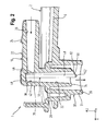
- einen Vertikalschnitt durch den Getränkeauslauf,
- Figur 3
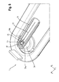
- einen Horizontalschnitt durch den Getränkeauslauf,
- Figur 4
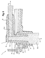
- den Vertikalschnitt durch den Getränkeauslauf mit einer ersten Getränkestromführung,
- Figur 5
- den Horizontalschnitt durch den Getränkeauslauf mit der ersten Getränkestromführung,
- Figur 6
- den Vertikalschnitt durch den Getränkeauslauf mit einer zweiten Getränkestromführung,
- Figur 7
- den Horizontalschnitt durch den Getränkeauslauf mit der zweiten Getränkestromführung, und
- Figur 8
- einen Fertigungsschritt zur Herstellung des Getränkeauslaufs.
-
Figur 1 zeigt ein Ausführungsbeispiel eines erfindungsgemäßen Getränkeauslaufs 1 für einen Getränkespender zum Zapfen einer zu einem Getränk aufbereiteten Flüssigkeit, Der Getränkeauslauf 1 hat ein längliches Führungselement 2 zur Aufnahme in einer Schiebekulisse des Getränkespenders und ein Auslaufelement 4 zur Entnahme des Getränkes bzw. der aufbereiteten Flüssigkeit. Unter dem Begriff Getränk bzw. Flüssigkeit wird im Folgenden sowohl ein geschmackliches Heißgetränk wie Kaffee als auch ein geschmacksneutrales Heißgetränk wie Heißwasser verstanden. - Das Führungselement 2 hat eine Grundplatte 6, von der sich zwei in Längsrichtung x des Getränkeauslaufs 1 erstreckende Seitenwandungen 8a, 8b und eine bogenförmige Stirnwandung 10 erstreckt, die die Seitenwandungen 8a, 8b kopfseitig miteinander verbindet. Die Seitenwandungen 8a, 8b sind keilartig in Richtung der Stirnwandung 10 verjüngt ausgebildet. Heckseitig ist der Getränkeauslauf 1 geöffnet. Zum Zusammenwirken mit der Schiebekulisse des Getränkespenders ist in den Wandungen 8a, 8b, 10 eine außenliegende und durchgehende Führungsnut 12 ausgebildet. Diese ist derart in die Wandungen 8a, 8b, 10 integriert, dass der Getränkeauslauf 1 mit einer Außenfläche des Getränkespenders eine bündige Sichtfläche bildet. Zur Verrastung des Getränkeauslaufs 1 mit der Schiebekulisse ist heckseitig in seitlichen Nutabschnitten der Führungsnut 12 jeweils eine Rastnase 16 zur Verrastung mit jeweils einer schiebekulissenseitigen Rastvertiefung bzw. mit einem schiebekulissenseitigen Rastvorsprung angeordnet. Alternativ können die Rastnasen 16 zur Sicherung des Getränkeauslaufs 1 mittels Reibschluss an der Schiebekulisse verwenden werden. Durch die Führungsnut 12 im Zusammenwirken mit der getränkespenderseitigen Schiebekulisse und der Verrastung wird eine schnelle und einfache Montage sowie Demontage des Getränkeauslaufs 1 und somit des Getränkespenders geschaffen. Zur Bildung eines stufenlosen Überganges mit einer Seitenwand des Getränkespenders ist die Grundplatte 6 heckseitig bogenförmig abgewinkelt, wodurch die Führungsnut 12 endseitig quasi keilförmig erweitert ist. Zudem ist heckseitig eine Schulter 14 ausgebildet, mit der sich der Getränkeauslauf 1 an der Seitenwand abstützt.
- Das Auslaufelement 4 ist im Stirnbereich bzw. Kopfbereich der Grundplatte 6 angeordnet. Es hat eine L-förmige Form mit einem Zulaufrohr 18 und mit einem abgewinkelten Auslaufrohr 20.
- Wie in
Figur 2 gezeigt, hat das Zulaufrohr 18 eine sich in Längsrichtung x des Getränkeauslaufs 1 erstreckende Längsachse xz. Es dient zur Anbindung an eine geräteinterne Getränkezuführung wie eine Verschlauchung und hat einen zylindrischen Au-βenumfang 22, an dem zumindest ein Keilvorsprung 24 zur Sicherung der Getränkezuführung ausgebildet ist. Das Zulaufrohr 18 eine Innenwandung 26, die einen in Zulaufrichtung konisch verjüngten Zulaufquerschnitt definiert. Die Zulaufrichtung ist durch den gemäß der Darstellung inFigur 2 waagerechten Pfeil angedeutet. - Das Auslaufrohr 20 hat eine sich in Hochrichtung z des Getränkeauslaufs 1 erstreckende Längsachse xa. Es durchsetzt eine Bodenwandung 28 eines becherartigen Körpers 30, der eine in Auslaufrichtung konisch erweiterte Umfangswandung 31 hat, die sich durch die Grundplatte 6 des Führungselementes 2 erstreckt. Das Auslaufrohr 20 hat eine Innenwandung 32, die einen in Auslaufrichtung konisch erweiterten Auslaufquerschnitt definiert. Die Auslaufrichtung ist durch den gemäß der Darstellung in
Figur 2 vertikalen Pfeil angedeutet. Zudem weist es einen ringförmigen Austrittsrand 34 auf, der stromaufwärts eines Mündungsrandes 36 des becherartigen Körpers 30 angeordnet ist. - Zur Zuführung des Getränkestroms aus dem Zulaufrohr 18 in das Auslaufrohr 20 ist stromabwärts des Zulaufrohrs 18 und stromaufwärts des Auslaufrohrs 20 ein integral mit dem Zulaufrohr 18 und dem Auslaufrohr 20 ausgebildeter Umlenkbereich 38 vorgesehen. Der Umlenkbereich 38 ist in
Figur 2 durch die gestrichelten Linien zeichnerisch angedeutet und stellt eine fluidtechnische Verbindung zwischen den beiden Rohren 18, 20 her. Er bewirkt eine Umlenkung des Getränkestroms 39 (Figuren 4 bis 7 ) aus der Zulaufrichtung in die Auslaufrichtung. Im gezeigten Ausführungsbeispiel wird der Getränkestrom 39 um 90° umgelenkt. Der Umlenkbereich 38 hat eine Begrenzungswandung 40, die sich in Zulaufrichtung erstreckt und stufenförmig zur Innenwandung 26 des Zulaufrohrs 18 zurückgesetzt ist. Zudem hat der Umlenkbereich 38 eine Umlenkwandung 42, die sich in Auslaufrichtung erstreckt und stufenlos in die Innenwandung 32 des Auslaufrohrs 18 übergeht. - Zum Leiten des Getränkestroms und somit zur Optimierung eines Strahlbildes ist ein Leitelement 44 vorgesehen. Das Leitelement 44 hat eine plattenartige Gestalt mit einer Vorderkante 46, einer Hinterkante 48, einer Auslaufkante 50 und mit einer Tropfnase 52.
- Wie in den
Figuren 2 und3 dargestellt, ist das Leitelement 44 mit seiner Längsachse xl in Auslaufrichtung und mit seiner Querachse yl in Zulaufrichtung orientiert. Es erstreckt sich wandartig von einem Innenwandungsabschnitt 54 des Auslaufrohrs 20 und ist kopfseitig an der Begrenzungswandung 40 des Umlenkbereiches 38 angebunden. - Die Vorderkante 46 (
Figur 2 ) ist eine in Zulaufrichtung betrachtet vordere Seitenkante des Leitelementes 44. Sie durchsetzt den Umlenkbereich 38 und erstreckt sich somit in Hochrichtung z des Getränkeauslaufs 1 über den gesamten Zulaufquerschnitt. Sie kreuzt die Längsachse xz des Zulaufrohrs 18 und ist somit mittig des das Zulaufrohr 18 durchströmenden Getränkestroms 39 (Figuren 4 bis 7 ) angeordnet. Sie hat eine konkave Anströmfläche 56 und zwei voneinander abgewandte Seitenflächen 58a, 58b, die parallel zueinander orientiert sind. - Die Hinterkante 48 (
Figuren 2 und3 ) ist eine in Zulaufrichtung betrachtet hintere Seitenkante des Leitelementes 44. Sie verläuft in Längsrichtung xl des Leitelements 44 und somit in Auslaufrichtung. Sie ist gegenüber einem in Zulaufrichtung betrachtet stromaufwärtigen Leitelementenabschnitt kugelartig erweitert. In dem gezeigten Ausführungsbeispiel ist der Leitelementenabschnitt von den voneinander abgewandten Seitenflächen 58a, 58b und somit von der Vorderkante 46 gebildet. Sie hat eine die Seitenflächen 58a, 58b miteinander verbindende konkave Kantenfläche 60, die stromabwärts in die Tropfnase 52 übergeht. - Die Auslaufkante 50 (
Figur 2 ) ist in etwa quer zur Vorderkante 46 und zur Hinterkante 48 orientiert. Sie erstreckt sich vom Austrittsrand 34 und geht schräg zur Auslaufrichtung in die Tropfnase 52 über. Zur verbesserten Führung der das Leitelement 44 benetzenden Flüssigkeit hat sie eine konkave Führungsfläche 62. Zur verbesserten Führung der Flüssigkeit von der Innenwandung 32 des Auslaufrohrs 20 zur Auslaufkante 50 kann der Auslaufrand 34 schräg in Auslaufrichtung angestellt sein und mit einem stromabwärtigsten Bereich versehen sein der quasi als eine Senke wirkt und an dem die Austrittskante 50 angebunden ist bzw. von der sich die Auslaufkante 50 in Richtung der Tropfnase 52 erstreckt. - Die Tropfnase 52 (
Figur 2 ) ist stromabwärts des Austrittsrands 34 angeordnet. Sie ist als eine radial innere beulenartige Erhebung der Auslaufkante 50 ausgebildet. Sie bildet einen stromabwärtigsten Bereich des Leitelements 44 und somit quasi eine Senke, zu der jegliche das Leitelement 44 benetzende Flüssigkeit geführt wird und von der diese dann kontrolliert von dem Leitelement 44 abströmt. - Im Folgenden werden anhand der
Figuren 4 ,5 ,6 und7 Funktionsweisen des Leitelements 44 beispielhaft erläutert. - Die Flüssigkeit bzw. das Getränk wird über die Getränkezuführung dem Auslaufelement 4 zugeführt. In dem Zulaufrohr 18 bildet sich der Getränkestrom 39 aus, der das Zulaufrohr 18 in Zulaufrichtung und somit in Längsrichtung x des Getränkeauslaufs 1 durchströmt. Im Mündungsbereich zum Umlenkbereich 38 trifft der Getränkestrom 39 auf die Vorderkante 46 des Leitelements 44 auf und wird als zwei Einzelströme 39a, 39b um das Leitelement 44 geführt.
- Bei großen Durchflussmengen werden, wie in den
Figuren 4 und5 gezeigt, die Einzelströme 39a, 39b in Zulaufrichtung betrachtet im Wesentlichen hinter der Hinterkante 48 wieder zum Getränkestrom 39 zusammengeführt und im Umlenkbereich 38 beim Auftreffen auf den Wandungsabschnitt 42 in Auslaufrichtung und somit in Hochrichtung z des Getränkeauslaufs 1 um 90° umgelenkt. Der Getränkestrom 39 strömt das Auslaufrohr 20 hinab und tritt stromabwärts aus diesem aus. Selbstverständlich werden beim Auftreffen der Einzelströme 39a, 39b auf die Hinterkante 48 nicht skizzierte Teilströme gebildet. Die Teilströme werden durch die Hinterkante 48 in Auslaufrichtung umgelenkt, dann entlang der Auslaufkante 50 zur Tropfnase 52 geführt, von dieser von dem Leitelement 44 abströmen und dann in den wieder zusammengeführten Getränkestrom 39 übergehen. - Bei geringen Durchflussmengen wie am Ende eines Zapfvorgangs verhindert die verdickte Hinterkante 48 eine Zusammenführung der Einzelströme 39, 39b in Zulaufrichtung hinter der Hinterkante 48. Die Hinterkante 48 stellt quasi eine Barriere dar, die von den Einzelströmen 39a, 39b nicht überwunden werden kann. Die Einzelströme 39a, 39b werden, wie in den
Figur 6 und7 gezeigt, an der Hinterkante 48 im Bereich des Umlenkbereichs 38 in Auslaufrichtung um 90° umgelenkt und strömen als Einzelströme 39a, 39b entlang der Seitenflächen 58a, 58b in Richtung der Auslaufkante 50. Die Einzelströme 39a, 39b umströmen die Auslaufkante 50 und werden wieder zum Getränkestrom 39 zusammengeführt. Dieser fließt aufgrund der Schrägstellung der Auslaufkante 50 in Richtung der Tropfnase 52 und strömt von dieser kontrolliert ohne Tropfenbildung ab. - Die Flüssigkeit, die die Innenwandung 32 des Auslaufrohrs 20 benetzt, fließt in Richtung des Austrittsrandes 34 und wird von diesem zur Auslaufkante 50 geführt, wo sie mit dem zur Tropfnase 52 orientierten Getränkestrom 39 zusammengeführt wird.
- Wie in
Figur 8 gezeigt, ist der Getränkeauslauf 1 als ein fertigungstechnisch einfach herzustellendes kunststoffbasiertes Spritzgussteil ausgeführt. Da das Zulaufrohr 18 und das Auslaufrohr 20 durch die konische Verjüngung in Zulaufrichtung bzw. die konische Erweiterung in Auslaufrichtung jeweils in Entformungsrichtung ez, ea konisch erweitert sind, können diese bequem durch eine rückwärtige Bewegung der in ihrem Inneren angeordneten Werkzeugkernen 64a, 64b entformt werden. Aufgrund der gegenüber der Innenwandung 26 des Zulaufrohrs 18 zurückgesetzten Begrenzungswand 40 weist der Werkzeugkern 64b zur Ausbildung des Umlenkbereichs 38 einen nicht bezifferten ersten integralen Endabschnitt auf. - Zudem erlaubt das Auslaufelement 4 eine gleichzeitige Ausbildung des becherartigen Körpers 30. Hierzu weist der Werkzeugkern 64b des Auslaufrohrs 20 einen zweiten integralen Endabschnitt 66 auf, der mit einem entsprechenden rückwärtigen Axialkragen 68 zur Ausbildung eines Ringraums 70 zwischen dem Auslaufrohr 20 und der Umfangswandung 31 des Körpers 30 versehen ist. Zusätzlich zur Verjüngung der Umfangswandung 31 in Richtung der Bodenwandung 28 ist zur radialen Erweiterung des Ringraums 70 in Entformungsrichtung ea das Auslaufrohr 20 außenumfangsseitig im Bereich seines Austrittsrandes 34 mit einer Anfasung 72 versehen, wodurch sich die Entformung des Auslaufrohrs 20 weiter vereinfachen lässt.
- Offenbart ist ein Getränkeauslauf für einen Getränkespender zum Zapfen eines Getränkes, mit einem Zulaufrohr zum Anschluss an eine geräteinterne Getränkezuführung, mit einem abgewinkelten Auslaufrohr zur Entnahme des Getränkes, die über einen Umlenkbereich miteinander in Fluidverbindung stehen, und mit einem Leitelement zum Leiten eines Getränkestroms innerhalb des Auslaufrohrs, wobei sich das Leitelement wandartig von einem Innenwandungsabschnitt des Auslaufrohres erstreckt und eine Vorderkante hat, die an dem Umlenkbereich angeordnet ist, sowie eine Auslaufkante aufweist, die schräg in Richtung einer Tropfnase orientiert ist, ein Verfahren zur Herstellung eines derartigen Getränkeauslaufs sowie ein Getränkespender mit einem derartigen Getränkeauslauf.
-
- 1
- Getränkeauslauf
- 2
- Führungselement
- 4
- Auslaufelement
- 6
- Grundplatte
- 8a, b
- Seitenwandung
- 10
- Stirnwandung
- 12
- Führungsnut
- 14
- Schulter
- 16
- Rastnase
- 18
- Zulaufrohr
- 20
- Auslaufrohr
- 22
- Außenumfang
- 24
- Keilvorsprung
- 26
- Innenwandung
- 28
- Bodenwandung
- 30
- Körper
- 31
- Umfangswandung
- 32
- Innenwandung
- 34
- Austrittsrand
- 36
- Mündungsrand
- 38
- Umlenkbereich
- 39
- Getränkestrom
- 39a,b
- Einzelstrom
- 40
- Begrenzungswandung
- 42
- Umlenkwandung
- 44
- Leitelement
- 46
- Vorderkante
- 48
- Hinterkante
- 50
- Auslaufkante
- 52
- Tropfnase
- 54
- Innenwandungsabschnitt
- 56
- Anströmfläche
- 58a, b
- Seitenfläche
- 60
- Kantenfläche
- 62
- Führungsfläche
- 64a, b
- Werkzeugkern
- 66
- Endabschnitt
- 68
- Axialkragen
- 70
- Ringraum
- 72
- Anfasung
- x
- Längsrichtung Getränkeauslauf
- xz
- Längsachse Zulaufrohr
- xa
- Längsachse Auslaufrohr
- xl
- Längsachse Leitelement
- yl
- Querachse Leitelement
- z
- Hochrichtung Getränkeauslauf
- ez
- Entformungsrichtung Zulaufrohr
- ea
- Entformungsrichtung Auslaufrohr
Claims (15)
- Getränkeauslauf (1) für einen Getränkespender zum Zapfen eines Getränkes, mit einem Zulaufrohr (18) zum Anschluss an eine geräteinterne Getränkezuführung, mit einem abgewinkelten Auslaufrohr (20) zur Entnahme des Getränkes, die über einen Umlenkbereich (38) miteinander in Fluidverbindung stehen, und mit einem Leitelement (44) zum Leiten eines Getränkestroms innerhalb des Auslaufrohrs, dadurch gekennzeichnet, dass sich das Leitelement (44) wandartig von einem Innenwandungsabschnitt (54) des Auslaufrohrs (20) erstreckt, und eine Vorderkante (46) hat, die in dem Umlenkbereich (38) angeordnet ist, sowie eine Auslaufkante (50) aufweist, die schräg in Richtung einer Tropfnase (52) orientiert ist.
- Getränkeauslauf nach Anspruch 1, wobei das Leitelement (44) eine im Vergleich zu einem in Zulaufrichtung betrachtet stromaufwärtigen Leitelementenabschnitt eine verdickte Hinterkante (48) hat, die sich in Auslaufrichtung erstreckt.
- Getränkeauslauf nach Anspruch 2, wobei die Hinterkante (48) in die Tropfnase (52) übergeht.
- Getränkeauslauf nach Anspruch 1, 2 oder 3, wobei das Leitelement (44) den Umlenkbereich (38) vollständig durchsetzt.
- Getränkeauslauf nach einem der vorhergehenden Ansprüche, wobei die Vorderkante (44) mittig im Zulaufquerschnitt des Zulaufrohrs (18) angeordnet ist.
- Getränkeauslauf nach Anspruch 5, wobei das Leitelement (44) mit seiner Querachse (yl) in Zulaufrichtung orientiert ist.
- Getränkeauslauf nach einem der vorhergehenden Ansprüche, wobei das Leitelement (44) um seine Längsachse (xl) verwunden ist.
- Getränkeauslauf nach einem der vorhergehenden Ansprüche, wobei die Vorderkante (46) eine konkave Anströmfläche (56) und zwei sich in Zulaufrichtung orientierte Seitenflächen (58a, 58b) hat, die parallel oder in Zulaufrichtung schräg auseinanderlaufend oder in Zulaufrichtung aufeinander zulaufend orientiert sind.
- Getränkeauslauf nach einem der vorhergehenden Ansprüche, wobei die Seitenflächen (58a, 58b) jeweils zumindest eine in Richtung der Tropfnase (52) orientierte Leithilfe aufweisen.
- Getränkeauslauf nach einem der vorhergehenden Ansprüche, wobei sich die Auslaufkante (50) von einem Austrittsrand (34) des Auslaufrohrs (20) erstreckt und die Tropfnase (52) stromabwärts des Austrittsrands (34) angeordnet ist.
- Getränkeauslauf nach Anspruch 10, wobei der Austrittsrand (34) schräg zur Längsachse (xl) des Auslaufrohrs (20) angestellt ist und die Auslaufkante (50) in einem Randabschnitt angeordnet ist, der eine Senke des Auslaufrandes (34) darstellt.
- Getränkeauslauf nach einem der vorhergehenden Ansprüche, wobei der Zulaufquerschnitt des Zulaufrohrs (18) in Zulaufrichtung konisch verjüngt ist.
- Getränkeauslauf nach einem der vorhergehenden Ansprüche, wobei das Auslaufrohr (20) einen in Auslaufrichtung konisch erweiterten Auslaufquerschnitt hat.
- Verfahren zur Herstellung eines Getränkeauslaufs (1) nach einem der vorhergehenden Ansprüche, mit einem Zulaufrohr (18) und einem abgewinkelten Auslaufrohr (20), wobei der Getränkeauslauf (1) durch Spritzgießen hergestellt wird und in das Zulaufrohr (18) und das Auslaufrohr (20) Werkzeugkerne (64a, 64b) eingesetzt werden, die durch eine rückwärtige Bewegung aus diesen entnommen werden.
- Getränkespender mit einem Getränkeauslauf (1) nach einem der Ansprüche 1 bis 13.
Applications Claiming Priority (1)
| Application Number | Priority Date | Filing Date | Title |
|---|---|---|---|
| DE102011080094A DE102011080094A1 (de) | 2011-07-29 | 2011-07-29 | Getränkeauslauf, Verfahren und Getränkespender |
Publications (2)
| Publication Number | Publication Date |
|---|---|
| EP2550904A1 true EP2550904A1 (de) | 2013-01-30 |
| EP2550904B1 EP2550904B1 (de) | 2014-07-02 |
Family
ID=46506264
Family Applications (1)
| Application Number | Title | Priority Date | Filing Date |
|---|---|---|---|
| EP12176054.0A Active EP2550904B1 (de) | 2011-07-29 | 2012-07-12 | Getränkeauslauf, Verfahren und Getränkespender |
Country Status (2)
| Country | Link |
|---|---|
| EP (1) | EP2550904B1 (de) |
| DE (1) | DE102011080094A1 (de) |
Citations (4)
| Publication number | Priority date | Publication date | Assignee | Title |
|---|---|---|---|---|
| DE6913213U (de) * | 1968-04-03 | 1969-11-27 | Imi Dev Ltd | Zapfhahnkoerper und verfahren zu seiner herstellung |
| DE2732054A1 (de) | 1977-07-15 | 1979-02-01 | Krups Fa Robert | Auslaufrohr fuer fluessigkeitsbehaelter |
| DE3503556A1 (de) * | 1985-02-02 | 1986-08-07 | Licentia Patent-Verwaltungs-Gmbh, 6000 Frankfurt | Heisswasserbereiter, der als saeulenartiges tischgeraet ausgebildet ist |
| CN101703361B (zh) * | 2009-11-19 | 2011-06-08 | 宁波意中咖啡机有限公司 | 咖啡机精沫装置 |
-
2011
- 2011-07-29 DE DE102011080094A patent/DE102011080094A1/de not_active Ceased
-
2012
- 2012-07-12 EP EP12176054.0A patent/EP2550904B1/de active Active
Patent Citations (5)
| Publication number | Priority date | Publication date | Assignee | Title |
|---|---|---|---|---|
| DE6913213U (de) * | 1968-04-03 | 1969-11-27 | Imi Dev Ltd | Zapfhahnkoerper und verfahren zu seiner herstellung |
| DE2732054A1 (de) | 1977-07-15 | 1979-02-01 | Krups Fa Robert | Auslaufrohr fuer fluessigkeitsbehaelter |
| DE3503556A1 (de) * | 1985-02-02 | 1986-08-07 | Licentia Patent-Verwaltungs-Gmbh, 6000 Frankfurt | Heisswasserbereiter, der als saeulenartiges tischgeraet ausgebildet ist |
| DE3503556C2 (de) | 1985-02-02 | 1990-08-23 | Licentia Patent-Verwaltungs-Gmbh, 6000 Frankfurt, De | |
| CN101703361B (zh) * | 2009-11-19 | 2011-06-08 | 宁波意中咖啡机有限公司 | 咖啡机精沫装置 |
Also Published As
| Publication number | Publication date |
|---|---|
| EP2550904B1 (de) | 2014-07-02 |
| DE102011080094A1 (de) | 2013-01-31 |
Similar Documents
| Publication | Publication Date | Title |
|---|---|---|
| EP2969234B1 (de) | Zerstäuberdüse für einen sanitären wasserauslauf sowie sanitäre auslaufarmatur mit einem wasserauslauf | |
| EP1870003B1 (de) | Milchaufschäumvorrichtung | |
| EP2620223B1 (de) | Düseneinheit und Spender mit einer solchen | |
| DE112012005017B4 (de) | Vorrichtung zum Steuern einer Fluid-Strömung in einem Notfall-Waschsystem, Vorrichtung zum Steuern einer Fluid-Strömung und Waschsystem zum Liefern einer Fluid-Strömung | |
| EP2850253B1 (de) | Länglicher durchflussmengenregler mit steg- oder schnurförmigen drosselkörper | |
| EP2189226B1 (de) | Luftkappe mit separat ausgeformtem Luftrichter und deren Herstellungsverfahren mittels Spritzgießen | |
| DE102008054898A1 (de) | Stoffauflauf für eine Maschine zur Herstellung einer Faserstoffbahn | |
| DE102012104771B4 (de) | Spritzpistole | |
| DE102012013815B4 (de) | Kaltgasspritzpistole mit Pulverinjektor | |
| WO2017102139A1 (de) | Spritzlochscheibe und ventil | |
| DE19645961A1 (de) | Kraftstoffeinspritzvorrichtung für eine Gasturbinen-Brennkammer mit einer flüssigkeitsgekühlten Einspritzdüse | |
| EP3453805A1 (de) | Spülwasserverteiler | |
| DE19931890A1 (de) | Düsenkörper für eine Kraftstoffeinspritzdüse mit optimierter Spritzlochkanalgeometrie | |
| DE10392296B4 (de) | Vorrichtung zum Ausrichten eines Stromes eines Fluids und Kraftstoff-Zapfpistole mit einer solchen Vorrichtung | |
| EP2550904B1 (de) | Getränkeauslauf, Verfahren und Getränkespender | |
| EP3088087B1 (de) | Sprühdüse und verfahren zum erzeugen von nicht runden sprühkegeln | |
| WO2009003555A1 (de) | Vorrichtung zum aufteilen einer mittels einer gasströmung transportieren flüssigkeit | |
| DE102012014665A1 (de) | Brenner zum Lichtbogendrahtspritzen | |
| EP4269062B1 (de) | Düsenspitze für eine heisskanaldüse | |
| EP3546421A1 (de) | Zapfvorrichtung aufweisend einen düseneinsatz mit einer prallwand | |
| DE4312994C2 (de) | Vorrichtung zur Verspritzung von Suspensionen, insbesondere Mörteln | |
| WO2011095250A1 (de) | Ventil zum regulieren eines fluidstroms | |
| DE102013002235B4 (de) | Luftansaugvorrichtung für eine Sanitärbrause | |
| AT516150A4 (de) | Zylinderkopf einer brennkraftmaschine | |
| EP4129489B1 (de) | Flachstrahldüse |
Legal Events
| Date | Code | Title | Description |
|---|---|---|---|
| PUAI | Public reference made under article 153(3) epc to a published international application that has entered the european phase |
Free format text: ORIGINAL CODE: 0009012 |
|
| AK | Designated contracting states |
Kind code of ref document: A1 Designated state(s): AL AT BE BG CH CY CZ DE DK EE ES FI FR GB GR HR HU IE IS IT LI LT LU LV MC MK MT NL NO PL PT RO RS SE SI SK SM TR |
|
| AX | Request for extension of the european patent |
Extension state: BA ME |
|
| 17P | Request for examination filed |
Effective date: 20130730 |
|
| RBV | Designated contracting states (corrected) |
Designated state(s): AL AT BE BG CH CY CZ DE DK EE ES FI FR GB GR HR HU IE IS IT LI LT LU LV MC MK MT NL NO PL PT RO RS SE SI SK SM TR |
|
| RIC1 | Information provided on ipc code assigned before grant |
Ipc: A47J 31/46 20060101AFI20130814BHEP |
|
| GRAP | Despatch of communication of intention to grant a patent |
Free format text: ORIGINAL CODE: EPIDOSNIGR1 |
|
| INTG | Intention to grant announced |
Effective date: 20140218 |
|
| GRAS | Grant fee paid |
Free format text: ORIGINAL CODE: EPIDOSNIGR3 |
|
| GRAA | (expected) grant |
Free format text: ORIGINAL CODE: 0009210 |
|
| AK | Designated contracting states |
Kind code of ref document: B1 Designated state(s): AL AT BE BG CH CY CZ DE DK EE ES FI FR GB GR HR HU IE IS IT LI LT LU LV MC MK MT NL NO PL PT RO RS SE SI SK SM TR |
|
| REG | Reference to a national code |
Ref country code: GB Ref legal event code: FG4D Free format text: NOT ENGLISH |
|
| REG | Reference to a national code |
Ref country code: CH Ref legal event code: EP Ref country code: AT Ref legal event code: REF Ref document number: 675432 Country of ref document: AT Kind code of ref document: T Effective date: 20140715 |
|
| REG | Reference to a national code |
Ref country code: IE Ref legal event code: FG4D Free format text: LANGUAGE OF EP DOCUMENT: GERMAN |
|
| REG | Reference to a national code |
Ref country code: DE Ref legal event code: R096 Ref document number: 502012000956 Country of ref document: DE Effective date: 20140814 |
|
| REG | Reference to a national code |
Ref country code: NL Ref legal event code: VDEP Effective date: 20140702 |
|
| REG | Reference to a national code |
Ref country code: LT Ref legal event code: MG4D |
|
| PG25 | Lapsed in a contracting state [announced via postgrant information from national office to epo] |
Ref country code: GR Free format text: LAPSE BECAUSE OF FAILURE TO SUBMIT A TRANSLATION OF THE DESCRIPTION OR TO PAY THE FEE WITHIN THE PRESCRIBED TIME-LIMIT Effective date: 20141003 Ref country code: ES Free format text: LAPSE BECAUSE OF FAILURE TO SUBMIT A TRANSLATION OF THE DESCRIPTION OR TO PAY THE FEE WITHIN THE PRESCRIBED TIME-LIMIT Effective date: 20140702 Ref country code: SE Free format text: LAPSE BECAUSE OF FAILURE TO SUBMIT A TRANSLATION OF THE DESCRIPTION OR TO PAY THE FEE WITHIN THE PRESCRIBED TIME-LIMIT Effective date: 20140702 Ref country code: CZ Free format text: LAPSE BECAUSE OF FAILURE TO SUBMIT A TRANSLATION OF THE DESCRIPTION OR TO PAY THE FEE WITHIN THE PRESCRIBED TIME-LIMIT Effective date: 20140702 Ref country code: BG Free format text: LAPSE BECAUSE OF FAILURE TO SUBMIT A TRANSLATION OF THE DESCRIPTION OR TO PAY THE FEE WITHIN THE PRESCRIBED TIME-LIMIT Effective date: 20141002 Ref country code: PT Free format text: LAPSE BECAUSE OF FAILURE TO SUBMIT A TRANSLATION OF THE DESCRIPTION OR TO PAY THE FEE WITHIN THE PRESCRIBED TIME-LIMIT Effective date: 20141103 Ref country code: NO Free format text: LAPSE BECAUSE OF FAILURE TO SUBMIT A TRANSLATION OF THE DESCRIPTION OR TO PAY THE FEE WITHIN THE PRESCRIBED TIME-LIMIT Effective date: 20141002 Ref country code: LT Free format text: LAPSE BECAUSE OF FAILURE TO SUBMIT A TRANSLATION OF THE DESCRIPTION OR TO PAY THE FEE WITHIN THE PRESCRIBED TIME-LIMIT Effective date: 20140702 Ref country code: FI Free format text: LAPSE BECAUSE OF FAILURE TO SUBMIT A TRANSLATION OF THE DESCRIPTION OR TO PAY THE FEE WITHIN THE PRESCRIBED TIME-LIMIT Effective date: 20140702 |
|
| PG25 | Lapsed in a contracting state [announced via postgrant information from national office to epo] |
Ref country code: LV Free format text: LAPSE BECAUSE OF FAILURE TO SUBMIT A TRANSLATION OF THE DESCRIPTION OR TO PAY THE FEE WITHIN THE PRESCRIBED TIME-LIMIT Effective date: 20140702 Ref country code: NL Free format text: LAPSE BECAUSE OF FAILURE TO SUBMIT A TRANSLATION OF THE DESCRIPTION OR TO PAY THE FEE WITHIN THE PRESCRIBED TIME-LIMIT Effective date: 20140702 Ref country code: HR Free format text: LAPSE BECAUSE OF FAILURE TO SUBMIT A TRANSLATION OF THE DESCRIPTION OR TO PAY THE FEE WITHIN THE PRESCRIBED TIME-LIMIT Effective date: 20140702 Ref country code: PL Free format text: LAPSE BECAUSE OF FAILURE TO SUBMIT A TRANSLATION OF THE DESCRIPTION OR TO PAY THE FEE WITHIN THE PRESCRIBED TIME-LIMIT Effective date: 20140702 Ref country code: CY Free format text: LAPSE BECAUSE OF FAILURE TO SUBMIT A TRANSLATION OF THE DESCRIPTION OR TO PAY THE FEE WITHIN THE PRESCRIBED TIME-LIMIT Effective date: 20140702 Ref country code: RS Free format text: LAPSE BECAUSE OF FAILURE TO SUBMIT A TRANSLATION OF THE DESCRIPTION OR TO PAY THE FEE WITHIN THE PRESCRIBED TIME-LIMIT Effective date: 20140702 Ref country code: IS Free format text: LAPSE BECAUSE OF FAILURE TO SUBMIT A TRANSLATION OF THE DESCRIPTION OR TO PAY THE FEE WITHIN THE PRESCRIBED TIME-LIMIT Effective date: 20141102 |
|
| REG | Reference to a national code |
Ref country code: CH Ref legal event code: PFA Owner name: BSH HAUSGERAETE GMBH, DE Free format text: FORMER OWNER: BSH BOSCH UND SIEMENS HAUSGERAETE GMBH, DE |
|
| RAP2 | Party data changed (patent owner data changed or rights of a patent transferred) |
Owner name: BSH HAUSGERAETE GMBH |
|
| REG | Reference to a national code |
Ref country code: DE Ref legal event code: R097 Ref document number: 502012000956 Country of ref document: DE |
|
| REG | Reference to a national code |
Ref country code: IE Ref legal event code: MM4A |
|
| PG25 | Lapsed in a contracting state [announced via postgrant information from national office to epo] |
Ref country code: SK Free format text: LAPSE BECAUSE OF FAILURE TO SUBMIT A TRANSLATION OF THE DESCRIPTION OR TO PAY THE FEE WITHIN THE PRESCRIBED TIME-LIMIT Effective date: 20140702 Ref country code: DK Free format text: LAPSE BECAUSE OF FAILURE TO SUBMIT A TRANSLATION OF THE DESCRIPTION OR TO PAY THE FEE WITHIN THE PRESCRIBED TIME-LIMIT Effective date: 20140702 Ref country code: MC Free format text: LAPSE BECAUSE OF FAILURE TO SUBMIT A TRANSLATION OF THE DESCRIPTION OR TO PAY THE FEE WITHIN THE PRESCRIBED TIME-LIMIT Effective date: 20140702 Ref country code: EE Free format text: LAPSE BECAUSE OF FAILURE TO SUBMIT A TRANSLATION OF THE DESCRIPTION OR TO PAY THE FEE WITHIN THE PRESCRIBED TIME-LIMIT Effective date: 20140702 Ref country code: IT Free format text: LAPSE BECAUSE OF FAILURE TO SUBMIT A TRANSLATION OF THE DESCRIPTION OR TO PAY THE FEE WITHIN THE PRESCRIBED TIME-LIMIT Effective date: 20140702 Ref country code: RO Free format text: LAPSE BECAUSE OF FAILURE TO SUBMIT A TRANSLATION OF THE DESCRIPTION OR TO PAY THE FEE WITHIN THE PRESCRIBED TIME-LIMIT Effective date: 20140702 |
|
| PLBE | No opposition filed within time limit |
Free format text: ORIGINAL CODE: 0009261 |
|
| STAA | Information on the status of an ep patent application or granted ep patent |
Free format text: STATUS: NO OPPOSITION FILED WITHIN TIME LIMIT |
|
| REG | Reference to a national code |
Ref country code: DE Ref legal event code: R081 Ref document number: 502012000956 Country of ref document: DE Owner name: BSH HAUSGERAETE GMBH, DE Free format text: FORMER OWNER: BSH BOSCH UND SIEMENS HAUSGERAETE GMBH, 81739 MUENCHEN, DE Effective date: 20150409 |
|
| 26N | No opposition filed |
Effective date: 20150407 |
|
| REG | Reference to a national code |
Ref country code: FR Ref legal event code: PLFP Year of fee payment: 4 |
|
| PG25 | Lapsed in a contracting state [announced via postgrant information from national office to epo] |
Ref country code: IE Free format text: LAPSE BECAUSE OF NON-PAYMENT OF DUE FEES Effective date: 20140712 |
|
| REG | Reference to a national code |
Ref country code: FR Ref legal event code: CD Owner name: BSH HAUSGERATE GMBH, DE Effective date: 20151022 |
|
| PG25 | Lapsed in a contracting state [announced via postgrant information from national office to epo] |
Ref country code: SI Free format text: LAPSE BECAUSE OF FAILURE TO SUBMIT A TRANSLATION OF THE DESCRIPTION OR TO PAY THE FEE WITHIN THE PRESCRIBED TIME-LIMIT Effective date: 20140702 |
|
| REG | Reference to a national code |
Ref country code: CH Ref legal event code: PL |
|
| PG25 | Lapsed in a contracting state [announced via postgrant information from national office to epo] |
Ref country code: CH Free format text: LAPSE BECAUSE OF NON-PAYMENT OF DUE FEES Effective date: 20150731 Ref country code: LI Free format text: LAPSE BECAUSE OF NON-PAYMENT OF DUE FEES Effective date: 20150731 Ref country code: SM Free format text: LAPSE BECAUSE OF FAILURE TO SUBMIT A TRANSLATION OF THE DESCRIPTION OR TO PAY THE FEE WITHIN THE PRESCRIBED TIME-LIMIT Effective date: 20140702 |
|
| PG25 | Lapsed in a contracting state [announced via postgrant information from national office to epo] |
Ref country code: MT Free format text: LAPSE BECAUSE OF FAILURE TO SUBMIT A TRANSLATION OF THE DESCRIPTION OR TO PAY THE FEE WITHIN THE PRESCRIBED TIME-LIMIT Effective date: 20140702 |
|
| REG | Reference to a national code |
Ref country code: FR Ref legal event code: PLFP Year of fee payment: 5 |
|
| PG25 | Lapsed in a contracting state [announced via postgrant information from national office to epo] |
Ref country code: BE Free format text: LAPSE BECAUSE OF FAILURE TO SUBMIT A TRANSLATION OF THE DESCRIPTION OR TO PAY THE FEE WITHIN THE PRESCRIBED TIME-LIMIT Effective date: 20140731 Ref country code: LU Free format text: LAPSE BECAUSE OF NON-PAYMENT OF DUE FEES Effective date: 20140712 Ref country code: HU Free format text: LAPSE BECAUSE OF FAILURE TO SUBMIT A TRANSLATION OF THE DESCRIPTION OR TO PAY THE FEE WITHIN THE PRESCRIBED TIME-LIMIT; INVALID AB INITIO Effective date: 20120712 Ref country code: TR Free format text: LAPSE BECAUSE OF FAILURE TO SUBMIT A TRANSLATION OF THE DESCRIPTION OR TO PAY THE FEE WITHIN THE PRESCRIBED TIME-LIMIT Effective date: 20140702 |
|
| REG | Reference to a national code |
Ref country code: FR Ref legal event code: PLFP Year of fee payment: 6 |
|
| PG25 | Lapsed in a contracting state [announced via postgrant information from national office to epo] |
Ref country code: MK Free format text: LAPSE BECAUSE OF FAILURE TO SUBMIT A TRANSLATION OF THE DESCRIPTION OR TO PAY THE FEE WITHIN THE PRESCRIBED TIME-LIMIT Effective date: 20140702 |
|
| REG | Reference to a national code |
Ref country code: FR Ref legal event code: PLFP Year of fee payment: 7 |
|
| REG | Reference to a national code |
Ref country code: AT Ref legal event code: MM01 Ref document number: 675432 Country of ref document: AT Kind code of ref document: T Effective date: 20170712 |
|
| PG25 | Lapsed in a contracting state [announced via postgrant information from national office to epo] |
Ref country code: AL Free format text: LAPSE BECAUSE OF FAILURE TO SUBMIT A TRANSLATION OF THE DESCRIPTION OR TO PAY THE FEE WITHIN THE PRESCRIBED TIME-LIMIT Effective date: 20140702 |
|
| PG25 | Lapsed in a contracting state [announced via postgrant information from national office to epo] |
Ref country code: AT Free format text: LAPSE BECAUSE OF NON-PAYMENT OF DUE FEES Effective date: 20170712 |
|
| PGFP | Annual fee paid to national office [announced via postgrant information from national office to epo] |
Ref country code: DE Payment date: 20250731 Year of fee payment: 14 |
|
| PGFP | Annual fee paid to national office [announced via postgrant information from national office to epo] |
Ref country code: GB Payment date: 20250724 Year of fee payment: 14 |
|
| PGFP | Annual fee paid to national office [announced via postgrant information from national office to epo] |
Ref country code: FR Payment date: 20250723 Year of fee payment: 14 |