EP2549946B1 - Dynamischer virtueller artikulator - Google Patents
Dynamischer virtueller artikulator Download PDFInfo
- Publication number
- EP2549946B1 EP2549946B1 EP11746885.0A EP11746885A EP2549946B1 EP 2549946 B1 EP2549946 B1 EP 2549946B1 EP 11746885 A EP11746885 A EP 11746885A EP 2549946 B1 EP2549946 B1 EP 2549946B1
- Authority
- EP
- European Patent Office
- Prior art keywords
- virtual
- teeth
- jaw
- articulator
- lower jaw
- Prior art date
- Legal status (The legal status is an assumption and is not a legal conclusion. Google has not performed a legal analysis and makes no representation as to the accuracy of the status listed.)
- Active
Links
- 230000033001 locomotion Effects 0.000 claims description 174
- 238000000034 method Methods 0.000 claims description 96
- 238000004088 simulation Methods 0.000 claims description 26
- 238000005259 measurement Methods 0.000 claims description 20
- 238000012360 testing method Methods 0.000 claims description 18
- 239000000463 material Substances 0.000 claims description 12
- 238000002591 computed tomography Methods 0.000 claims description 9
- 230000000149 penetrating effect Effects 0.000 claims description 9
- 239000003086 colorant Substances 0.000 claims description 4
- 238000005520 cutting process Methods 0.000 claims description 2
- 210000000515 tooth Anatomy 0.000 description 387
- 210000001847 jaw Anatomy 0.000 description 100
- 230000008901 benefit Effects 0.000 description 44
- 230000003068 static effect Effects 0.000 description 13
- 210000002455 dental arch Anatomy 0.000 description 9
- 230000001055 chewing effect Effects 0.000 description 6
- 238000002360 preparation method Methods 0.000 description 6
- 210000003625 skull Anatomy 0.000 description 6
- 238000013461 design Methods 0.000 description 5
- 230000001815 facial effect Effects 0.000 description 5
- 230000006870 function Effects 0.000 description 5
- 230000014509 gene expression Effects 0.000 description 5
- 238000012545 processing Methods 0.000 description 5
- 230000004044 response Effects 0.000 description 5
- 210000003484 anatomy Anatomy 0.000 description 4
- 238000006073 displacement reaction Methods 0.000 description 4
- 239000007943 implant Substances 0.000 description 4
- 238000004519 manufacturing process Methods 0.000 description 4
- 230000035515 penetration Effects 0.000 description 4
- 241000282465 Canis Species 0.000 description 3
- 239000005557 antagonist Substances 0.000 description 3
- 238000004364 calculation method Methods 0.000 description 3
- 230000008859 change Effects 0.000 description 3
- 238000004590 computer program Methods 0.000 description 3
- 238000007373 indentation Methods 0.000 description 3
- 210000004373 mandible Anatomy 0.000 description 3
- 238000012986 modification Methods 0.000 description 3
- 230000004048 modification Effects 0.000 description 3
- 210000003205 muscle Anatomy 0.000 description 3
- 210000001738 temporomandibular joint Anatomy 0.000 description 3
- 238000002604 ultrasonography Methods 0.000 description 3
- 241001653121 Glenoides Species 0.000 description 2
- 206010061274 Malocclusion Diseases 0.000 description 2
- ZPUCINDJVBIVPJ-LJISPDSOSA-N cocaine Chemical compound O([C@H]1C[C@@H]2CC[C@@H](N2C)[C@H]1C(=O)OC)C(=O)C1=CC=CC=C1 ZPUCINDJVBIVPJ-LJISPDSOSA-N 0.000 description 2
- 210000003464 cuspid Anatomy 0.000 description 2
- 238000012938 design process Methods 0.000 description 2
- 210000005069 ears Anatomy 0.000 description 2
- 238000005516 engineering process Methods 0.000 description 2
- 238000000227 grinding Methods 0.000 description 2
- 238000013507 mapping Methods 0.000 description 2
- 210000002050 maxilla Anatomy 0.000 description 2
- 239000007787 solid Substances 0.000 description 2
- 230000000007 visual effect Effects 0.000 description 2
- OKTJSMMVPCPJKN-UHFFFAOYSA-N Carbon Chemical compound [C] OKTJSMMVPCPJKN-UHFFFAOYSA-N 0.000 description 1
- 125000000174 L-prolyl group Chemical group [H]N1C([H])([H])C([H])([H])C([H])([H])[C@@]1([H])C(*)=O 0.000 description 1
- 208000006650 Overbite Diseases 0.000 description 1
- 206010041235 Snoring Diseases 0.000 description 1
- 238000013459 approach Methods 0.000 description 1
- 230000004888 barrier function Effects 0.000 description 1
- 229910052799 carbon Inorganic materials 0.000 description 1
- 238000004040 coloring Methods 0.000 description 1
- 238000011960 computer-aided design Methods 0.000 description 1
- 238000010276 construction Methods 0.000 description 1
- 239000002537 cosmetic Substances 0.000 description 1
- 230000001419 dependent effect Effects 0.000 description 1
- 201000010099 disease Diseases 0.000 description 1
- 208000037265 diseases, disorders, signs and symptoms Diseases 0.000 description 1
- 230000004064 dysfunction Effects 0.000 description 1
- 238000010230 functional analysis Methods 0.000 description 1
- 210000003128 head Anatomy 0.000 description 1
- 238000003384 imaging method Methods 0.000 description 1
- 210000004283 incisor Anatomy 0.000 description 1
- 238000010348 incorporation Methods 0.000 description 1
- 230000001788 irregular Effects 0.000 description 1
- 238000007726 management method Methods 0.000 description 1
- 239000002184 metal Substances 0.000 description 1
- 210000000537 nasal bone Anatomy 0.000 description 1
- 230000007935 neutral effect Effects 0.000 description 1
- 230000008569 process Effects 0.000 description 1
- 230000000284 resting effect Effects 0.000 description 1
- 230000011218 segmentation Effects 0.000 description 1
- 238000004513 sizing Methods 0.000 description 1
- 238000000638 solvent extraction Methods 0.000 description 1
- 238000003860 storage Methods 0.000 description 1
- 230000002123 temporal effect Effects 0.000 description 1
- 238000012546 transfer Methods 0.000 description 1
- 230000009466 transformation Effects 0.000 description 1
Images


Classifications
-
- A—HUMAN NECESSITIES
- A61—MEDICAL OR VETERINARY SCIENCE; HYGIENE
- A61C—DENTISTRY; APPARATUS OR METHODS FOR ORAL OR DENTAL HYGIENE
- A61C11/00—Dental articulators, i.e. for simulating movement of the temporo-mandibular joints; Articulation forms or mouldings
-
- A—HUMAN NECESSITIES
- A61—MEDICAL OR VETERINARY SCIENCE; HYGIENE
- A61C—DENTISTRY; APPARATUS OR METHODS FOR ORAL OR DENTAL HYGIENE
- A61C13/00—Dental prostheses; Making same
- A61C13/0003—Making bridge-work, inlays, implants or the like
- A61C13/0004—Computer-assisted sizing or machining of dental prostheses
-
- A—HUMAN NECESSITIES
- A61—MEDICAL OR VETERINARY SCIENCE; HYGIENE
- A61C—DENTISTRY; APPARATUS OR METHODS FOR ORAL OR DENTAL HYGIENE
- A61C19/00—Dental auxiliary appliances
- A61C19/04—Measuring instruments specially adapted for dentistry
- A61C19/05—Measuring instruments specially adapted for dentistry for determining occlusion
-
- A—HUMAN NECESSITIES
- A61—MEDICAL OR VETERINARY SCIENCE; HYGIENE
- A61C—DENTISTRY; APPARATUS OR METHODS FOR ORAL OR DENTAL HYGIENE
- A61C5/00—Filling or capping teeth
- A61C5/70—Tooth crowns; Making thereof
- A61C5/77—Methods or devices for making crowns
-
- A—HUMAN NECESSITIES
- A61—MEDICAL OR VETERINARY SCIENCE; HYGIENE
- A61C—DENTISTRY; APPARATUS OR METHODS FOR ORAL OR DENTAL HYGIENE
- A61C9/00—Impression cups, i.e. impression trays; Impression methods
- A61C9/004—Means or methods for taking digitized impressions
- A61C9/0046—Data acquisition means or methods
- A61C9/0053—Optical means or methods, e.g. scanning the teeth by a laser or light beam
-
- A—HUMAN NECESSITIES
- A61—MEDICAL OR VETERINARY SCIENCE; HYGIENE
- A61C—DENTISTRY; APPARATUS OR METHODS FOR ORAL OR DENTAL HYGIENE
- A61C19/00—Dental auxiliary appliances
- A61C19/04—Measuring instruments specially adapted for dentistry
- A61C19/045—Measuring instruments specially adapted for dentistry for recording mandibular movement, e.g. face bows
-
- A—HUMAN NECESSITIES
- A61—MEDICAL OR VETERINARY SCIENCE; HYGIENE
- A61C—DENTISTRY; APPARATUS OR METHODS FOR ORAL OR DENTAL HYGIENE
- A61C9/00—Impression cups, i.e. impression trays; Impression methods
- A61C9/004—Means or methods for taking digitized impressions
- A61C9/0046—Data acquisition means or methods
- A61C9/0086—Acoustic means or methods
-
- G—PHYSICS
- G16—INFORMATION AND COMMUNICATION TECHNOLOGY [ICT] SPECIALLY ADAPTED FOR SPECIFIC APPLICATION FIELDS
- G16H—HEALTHCARE INFORMATICS, i.e. INFORMATION AND COMMUNICATION TECHNOLOGY [ICT] SPECIALLY ADAPTED FOR THE HANDLING OR PROCESSING OF MEDICAL OR HEALTHCARE DATA
- G16H20/00—ICT specially adapted for therapies or health-improving plans, e.g. for handling prescriptions, for steering therapy or for monitoring patient compliance
- G16H20/40—ICT specially adapted for therapies or health-improving plans, e.g. for handling prescriptions, for steering therapy or for monitoring patient compliance relating to mechanical, radiation or invasive therapies, e.g. surgery, laser therapy, dialysis or acupuncture
Definitions
- This invention generally relates to a virtual articulator and to a method of performing virtual articulation. More particularly, the invention relates to a computer-implemented method of using a dynamic virtual articulator for simulating occlusion of teeth, when performing computer-aided designing of one or more dental restorations.
- An articulator is a mechanical device which provides a simplified geometrical model of the cranium for simulating the relative movements of the human jaws for testing occlusion of teeth.
- An articulator is used by a dental technician when modelling dental restorations for a patient, and the dental technician may alternate between modelling the restorations and evaluating the function of the bite or occlusion using the articulator.
- the dental technician can use carbon copy paper placed between the teeth of the two jaws in the articulator, and the colliding teeth will be thus colored, when the jaws are moved.
- WO08113313A discloses a method for the production of a denture comprising the following steps: collection of the biometric data of a patient, namely, the toothed or untoothed mandible and maxilla, the sizing of the jaws, the spatial position thereof relative to the skull, the condyle inclination and the movement of the mandible, and the recording of the mandible movement; implementation of the data in a virtual articulator which is made available in the main memory of the data processing equipment; CAD construction of the individual articulator preformed parts and dental molded bodies based on the collected patient data; production of the individual articulator molded bodies and dental molded bodies by means of a generative manufacturing process based on the recorded biometric data; incorporation of the individual articulator preformed parts and/or dental molded bodies into a standardized articulator housing, or complete generative manufacture of the articulator with individualized molded bodies.
- US2002048741 discloses a computer implemented method of creating a dental model for use in dental articulation, the method comprising the steps of: providing a first set of digital data corresponding to an upper arch image of at least a portion of an upper dental arch of a patient; providing a second set of digital data corresponding to a lower arch image of at least a portion of a lower dental arch of the patient; providing hinge axis data representative of the spatial orientation of at least one of the upper and lower dental arches relative to a hinge axis of the patient; providing bite alignment data representative of the spatial relationship between the upper dental arch and the lower dental arch of the patient; aligning the upper arch image and the lower arch image based on the bite alignment data; and creating a reference hinge axis relative to the aligned upper and lower arch images based on the hinge axis data.
- US2004172150A discloses a system for designing a virtual dental model comprising: a virtual articulator representing a three dimensional model of a patient's upper and lower dental arches including data defining a constraint of motion having a plurality of degrees of freedom between said upper and lower dental arches; a simulation analyzer to simulate said motion using said three dimensional model and analyze resulting contacts on portions of said upper and lower arches during said movement to provide contact data, said resulting contacts being characterized by a sequence in time of occurrence; and a designing module to design one of a virtual prosthesis for one of said upper and lower arches and a virtual desired dental modification using said contact data acquired from said simulation analyzer and said virtual articulator.
- US2007207441 relates to four dimensional modeling of jaw and tooth dynamics where methods and systems are described to digitally model the 4-dimensional dynamics of jaw and tooth motion using time-based 3-dimensional data. Complete upper and lower digital models are registered to time-based 3-dimensional intra-oral data to produce a true 4-dimensional model. Diagnostic and clinical applications include balancing the occlusion and characterizing the geometry of the temporomandibular joint.
- the 4-dimensional model is readily combined with conventional imaging methods such as CT to create a more complete virtual patient model.
- a standard centric axis coordinate system and a bite position is defined by: a) determining a lower occlusal plane using the complete lower model; b) setting the lower occlusal plane at a predetermined angle, approximately 15 degrees, to a reference horizontal; c) orienting the model of the lower dental arch with the jaw midline perpendicular to the centric axis; d) using a predetermined axis-incisal distance to complete the location of the lower model and the centric axis; and e) positioning the upper model with respect to the lower using a scan taken at a closed or bite position.
- WO09133131A discloses a method of using a computer based virtual articulator, the method comprising: loading a digital dental model of a patient into a computer running a virtual articulator simulation program, and simulating one or more virtual functional movements, evaluate at least one parameter related to the movement of the jaw when a dental modification is applied, the at least one parameter related to the movement of the jaw being selected from at least the amount of jaw movement in a certain direction, the speed at which a certain jaw movement is carried out and an angle around which a rotational jaw movement is carried out.
- US 6 152 731 A , US 2004/172150 A1 , and WO 03/092536 A1 disclose computer-implemented methods for simulating virtual articulators but they do not disclose any collision management system wherein the teeth of the upper and lower jaws are blocked from penetrating each other virtual surfaces, and wherein the virtual surfaces of the virtual restorations are penetrable.
- Disclosed is a computer-implemented method of using a dynamic virtual articulator for simulating occlusion of teeth, when performing computer-aided designing of one or more dental restorations for a patient, where the method comprises the steps of:
- Disclosed is a computer-implemented method of using a dynamic virtual articulator for simulating occlusion of teeth, when performing computer-aided designing of one or more dental restorations for a patient, where the method comprises the steps of:
- the virtual articulator is allowed to only perform movements which resembles and imitates the real-life situation in the mouth of a patient or the situation when using a physical articulator, thus the relative movement of the jaws are physiological realistic.
- the teeth in the upper and lower jaws in the virtual articulator resemble physical, solid teeth which can collide and touch each other but not penetrate each other.
- the expression teeth may mean the original teeth in the patient's mouth with and without restorations and restorations which completely replace one or more teeth.
- Teeth may mean the virtual teeth in the virtual upper and lower jaw model to which no restoration(s) is/are designed.
- the teeth in opposing jaw are thus not allowed to penetrate each other's virtual surfaces, when they collide as part as the occlusion simulation or test for which the virtual articulator is used.
- the teeth in the virtual articulator are configured to appear, act or behave as solid objects with an impenetrable surface and with a physical extent corresponding to teeth in a physical articulator.
- the articulated movements of the jaws are restricted by disallowing jaws, and thus the teeth in the jaws, to penetrate.
- the teeth in the jaws may be said to be impenetrable or to exhibit impenetrability, which is a quality of matter whereby two bodies cannot occupy the same space at the same time.
- opposing teeth in the upper and lower virtual jaw cannot occupy the same virtual space at the same time.
- the virtual articulator is configured to be a virtual geometric model, for example of and thereby equivalent to a mechanical system comprising a physical articulator.
- the virtual articulator automatically moves or allows the user to move the two jaws relative to each other. This movement is confined to the movement allowed by the articulator geometry.
- the jaws may consist of both preparation scans and designed models.
- the virtual articulation may be based on a generic model, a physiologic model, free-movement without constraints etc.
- the virtual articulator can be utilized at any point in the design process of designing dental restorations, such a crowns or bridges, whereby the size and shape of the designed restorations can be tested to check if it is correct, i.e. test whether there is space enough for the designed restorations in the mouth, when the jaws are moving relative to each other.
- a restoration may be a part of one or more teeth, and therefore the expression "collisions between teeth” is used in the present application, and this expression therefore also comprises or means collision between a tooth and a restoration, collision between restorations, collisions between unmodified teeth etc.
- a tooth can be both a tooth without a restoration or with a restoration.
- the term tooth and the term restoration may be used interchangeably about a tooth with a restoration or of a restoration completely replacing a tooth.
- the method comprises optionally providing that the designed restoration(s) is penetrable, when colliding with the opposite virtual jaw.
- the method comprises providing that the designed restoration(s) is blocked from being penetrable when colliding with the opposite virtual jaw.
- the method comprises providing that the designed restoration(s) is penetrable, when colliding with the opposite virtual jaw.
- the restorations can be penetrable or not when designing the restorations, depending on the preference of the operator or user of the software.
- the virtual three-dimensional model of the upper jaw and lower jaw may comprise the entire jaw or arch or a part of the entire jaw, corresponding to e.g. a number of teeth, such as half of the teeth in the jaw.
- jaw and arch may in some cases in this application be used to denote the same physiologic region.
- the present computer-implemented method may be implemented and executed in a software program which performs the virtual articulator simulation.
- the virtual articulator simulates the movements of a physical articulator or the movements of the real jaws in the mouth of a patient, and besides not allowing penetration of opposing teeth, the movement of the virtual articulator will also ensure that after teeth collide, the next movement of the virtual jaws will correspond to the movement of the teeth in the mouth or the jaws in a physical articulator will perform after collisions, which is continuing the direction of the motion taken the collisions into account, i.e. direction, velocity, angle of impact etc.
- Prior art discloses collisions between jaws, and the jaws penetrate each other during collisions.
- the models are shown to be penetrable, because they are virtual models, whereby there are no physical barriers between the models.
- the collisions are made to resemble a real life collision in the mouth or in a physical articulator.
- the present method comprises reproducing collisions between upper and lower jaw as real, physical collisions, where the colliding teeth cannot penetrate each other but glide past each other, which is the natural physical case.
- the colliding teeth can thus only contact each other, not penetrate, as they are virtually solidified physically instead of being represented as penetrable objects.
- the method further comprises simultaneous modeling of the one or more dental restorations and collision testing of the virtual upper jaw and virtual lower jaw.
- the method may alternatively and/additionally comprise designing one or more orthodontic procedures for the patient, and/or designing one or more prosthetic procedures for the patient, and/or performing a functional analysis of the patient's teeth.
- the method further comprises automatic modelling of dental restorations in opposite positions in the virtual upper jaw and virtual lower jaw, when dental restorations in opposite positions are requested.
- the virtual upper jaw and virtual lower jaw are configured to move relative to each other.
- the movement or motion may be a free motion, a restricted or constrained motion, a motion based on an articulator model, such as a physical, mechanical articulator model etc.
- the virtual upper jaw is fixed such that the virtual lower jaw is configured to move relative to the virtual upper jaw.
- the virtual upper jaw may be fixed in the virtual space comprising the virtual articulator and the upper and lower teeth models.
- the method comprises performing the collision testing of the virtual upper jaw and virtual lower jaw exclusively along the occlusal axis of the virtual articulator.
- the method further comprises fixing the virtual upper jaw to the occlusial axis such that the virtual lower jaw is configured to move relative to the virtual upper jaw.
- a common property of most physical articulators is that the lower part holding the lower jaw is fixed to the occlusial axis, because the lower part is resting on a table. The upper part can then be moved relative to the lower part. It is an advantage that according to the present method the upper jaw is fixed relative to the occlusial axis, which resembles the anatomy of the human cranium, where the upper jaw is fixed to the rest of the cranium and the lower jaw can move relative to the upper jaw. However, alternatively the lower jaw could be fixed to the occlusial axes.
- the method further comprises defining a search structure on the virtual upper jaw configured for searching on predefined circular paths around the occlusial axis for detecting collisions with the surface of the lower jaw model.
- the method further comprises that the virtual lower jaw is configured to automatically move through at least one predefined path of movement relative to the virtual upper jaw.
- the method further comprises detecting the first position on the occlusial axis at which the virtual upper jaw and the virtual lower jaw are in contact.
- each motion step along one of the other axes i.e. for each degrees of freedom, it may be calculated when and at which points the teeth in the jaws will collide along the occlusial axis. So for each movement of the jaws along any of the axes, the jaws may in principle or calculation-wise be closed and then opened along the occlusial axis for testing collision between teeth.
- predefined paths of movement along the occlusial axis may be configured, where it may be calculated how, when, where the jaws collide for different situations.
- a search structure on the upper jaw model specialized at searching on circular paths around the occlusial axis.
- a search structure may be used to perform collision test and response along the occlusial axis by searching from the surface of the lower jaw model. This makes real-time collision test and response possible. If the upper jaw and the search structure were not fixed, the search structure would otherwise need to be updated or recalculated, whenever the relative location of the jaw model and the occlusial axis changed, which would make real-time simulation infeasible.
- the collisions are configured to be registered and visually marked.
- An advantage of this embodiment is that when the collision points are registered and detected, entire surfaces of collision points are obtained, and the dental restorations can be designed, modeled or modified based on this.
- a surface of collision points may be denoted the trace or the trace of motion.
- collision points in a collision provides a surface of collision points.
- the surface of collision points may provide a trace of motion.
- the surface of collision points may be visualized and used to design the restoration(s) with.
- a collision depth map may be provided and updates with the surface of collision points.
- unmodified teeth When unmodified teeth are simulated relative to each other, their motion traces or their surfaces cannot penetrate each other. The same may be the case for a restoration relative to an unmodified tooth. However, it may alternatively be the case that when a restoration and an unmodified tooth are simulated relative to each other, the motion surface of the restoration may penetrate the unmodified tooth.
- collision surface or trace of collisions points or collision points surface is used for both describing when unmodified teeth are simulated to move relative to each where the teeth collide and do not penetrate each other and for describing when a restoration is simulated relative to unmodified teeth where the restoration may penetrate the unmodified teeth, i.e. the restoration and the unmodified may penetrate each other.
- the simulated collisions or collision surfaces between unmodified teeth may determine the motion which can be performed between the upper and lower teeth models.
- This determined motion may then be used and studied when designing the restoration.
- the virtually designed appliance or restoration can be cut or designed relative to the collision trace motion.
- the part of the one or more dental restorations which causes a collision is configured to be automatically removed from the respective virtual jaw.
- the user can remove the part, e.g. a part of material by selecting it manually in the software program performing the virtual articulator simulation.
- restorations were only made on one jaw at the time, not on both jaws simultaneously or concurrently.
- a crown on a tooth in the upper jaw and a bridge on teeth in the lower jaw, which are opposite to the tooth in upper jaw can now be designed simultaneously.
- teeth, including opposing teeth in the upper and lower jaw can be designed, and evaluated with regard to collisions and viewed simultaneously.
- the method further comprises that the movement of the virtual upper jaw and the virtual lower jaw relative to each other is configured to be digitally recorded.
- a predefined motion of the virtual upper jaw and the virtual lower jaw relative to each other is configured to be played.
- the predefined motion is configured to be automatically terminated based on one or more constraints.
- the constraints may be determined by the boundaries of the teeth.
- the constraints may be determined by the canines in the upper and lower touching each other.
- the method further comprises that during the movement of the virtual upper jaw and the virtual lower jaw relative to each other all the collisions occurring between teeth are registered, and after the movement is finished, modeling of the collision points of the restorations is performed.
- a movement of the jaws in a continuous motion is performed, i.e. such that one jaw performs a motion completely covering a plane of the other jaw, whereby all collisions between the two jaws, which are possible when taking physiological constraints into account, are registered.
- the collisions are accumulated, and after the movement is completed and all collisions are registered, then modeling of the collisions points on the restorations is performed.
- automatic modeling of all collision points of restorations are performed concurrently.
- modeling of restorations at each collision point can be performed concurrently, simultaneously, at one go etc..
- Each individual collision point does not need be modeled separately, but some or all collisions points of restorations can be modeled collectively.
- the modeling may comprise that the parts of the restorations which were detected as contact points are removed, which corresponds to manually removing material from a restoration.
- each collision point of a restoration is modeled separately.
- restorations are penetrable.
- teeth without restorations are impenetrable but the restorations, e.g. the part of a tooth which is a restoration, may be penetrable. This is an advantage when modeling the restorations.
- the virtual upper jaw and the virtual lower jaw are configured to bounce back off each other after a collision.
- the trace of movement may be recorded, so it can be used in the designing of the restoration(s).
- the movement of the virtual upper jaw and the virtual lower jaw relative to each other is configured to be performed in real-time corresponding to natural articulator movements.
- the method further comprises selecting a predefined geometrical model for the virtual articulator from among a number of predefined geometrical models. It is an advantage that the user can select a virtual geometrical model from a number of predefined geometrical models, since the models can represent physical, mechanical articulators of specific brands; geometrical models which the user has defined, standard geometrical models etc..
- the geometrical model can be a physiologic or biologic model etc., such as a model of the skull geometry. Thus the user can select a geometrical model which suits him or the specific patient case.
- the selected geometrical model may impose constraints on the movements, or the geometrical model may provide free movement.
- the selected geometrical model provides the basis for the articulation and/or occlusion which can be tested or simulated.
- the virtual dynamic articulator is configured to be selected from among a number of virtual articulators resembling physical articulators.
- the method further comprises selecting a number of degrees of freedom for the geometrical model.
- the method further comprises aligning the virtual upper jaw and virtual lower jaw to correspond to the anatomical alignment of the jaws in the mouth of the patient.
- This alignment may be defined as a standard alignment.
- the anatomical alignment of the jaws is determined by performing a measurement of the patient's facial geometry.
- the patient's facial geometry is determined by performing a face scanning of the patient.
- the face scanning may result in a three-dimensional (3D) representation of the patient's face.
- the face scanning may comprise single, still images or may comprise video comprising sequences of still images representing the face in motion.
- the patient's specific facial geometry can be determined by means of traditional face bow or face arches using electronics and optics, where the face bows are attached to e.g. the ears or on the outside of the jaw.
- the face bows measure the movements, and the mechanical articulator is adjusted according to this. Movements may comprise swinging of the jaws, opening of the mouth, dragging of the jaw forward, backwards etc.
- the method further comprises that the virtual lower jaw is configured to be moved by a user.
- both the virtual jaws may be moved relative to each other.
- the movement may comprise:
- the method further comprises positioning a virtual alignment plane relative to the virtual upper jaw and the virtual lower jaw, where the virtual upper jaw and virtual lower jaw defines a virtual model of the set of teeth, wherein the method comprises the steps of:
- the virtual upper model and/or the virtual lower model may be arranged in the virtual articulator first, and then the alignment plane is positioned afterwards or vice versa.
- the virtual alignment plane may also not be visualised, and may thus be invisible or faded.
- the virtual models can be aligned relative to a virtual alignment plane.
- the virtual alignment plane may be determined e.g. based a plane in a mechanical articulator.
- a marking e.g indentations in the vertical rods, for manually arranging a red rubber-band.
- the rubber band is used to arrange, such as align, the two physical models of the upper and lower teeth.
- the automatic positioning is based on one or more parameters.
- the method further comprises positioning a virtual alignment plane relative to the virtual upper jaw and the virtual lower jaw, where the virtual upper jaw and virtual lower jaw defines a virtual model of the set of teeth, wherein the method comprises the steps of:
- the virtual alignment plane and the virtual model of the teeth are positioned relative to each other based on some parameters, because depending on which parameters that are available for the specific patient and case, the relevant available parameters can be used to perform the positioning. If no specific parameters are available for the specific patient, standard or default parameters may be used. But if specific parameters are available for the patient, these parameters may be used such that the result can be achieved faster and with a better result.
- the patient-specific parameters may be obtained with a facebow providing information about static occlusion, with an electronic facebow providing information about static and dynamic occlusion, with a face scanner also providing information about static and dynamic occlusion etc..
- the virtual alignment plane may be defined or determined in different ways.
- the alignment plane may be flat, level or even, or curved, irregular, uneven or non-uniform etc.
- the alignment plane may follow or comply with the shape of the incisal or biting edges and/or cusps of the teeth.
- the alignment plane may for example be the curve of Spee.
- the curve of Spee is defined by that the cusp tips and incisal edges of the teeth align so that there is a smooth, linear curve when viewed from the lateral aspect.
- the lower curve of Spee is concave whereas the upper curve is convex.
- Curve of Spee may be called a compensating curve of the dental arch.
- the set of teeth may be an entire set of teeth covering all teeth in a patients mouth, or the set of teeth may be a part of an entire set of teeth, thus the set of teeth may also be denoted at least a part of a set of teeth.
- Positioning relative to means that either the virtual alignment plane is fixed in position when seen on e.g. a graphical user interface, such as a computer screen, and then the virtual model is moved, or it means that the virtual model is fixed in position when seen on e.g. the computer screen, and then the virtual alignment plane is moved. In either way the virtual model and the virtual alignment plane are seen to virtually move relative to each other.
- Positioning may be defined as placing, arranging etc. Occlusion may be defined as the contacts between the upper and lower teeth, or as the relationship between the maxillary (upper) and mandibular (lower) teeth when they approach each other, as occurs during chewing or at rest.
- the one or more parameters are derived from a face scan of the patient. It is an advantage that the one or more parameters can be derived from a face scan of the patient, where the movements of the jaws are scanned when the patient performs e.g. dynamic occlusion, because this allows for recording of dynamic movements of the jaw such that dynamic occlusion performed when chewing and open/close movements can be recorded.
- the face scan can alternatively and/or additionally be used to measure the static occlusion of the patient. These static occlusion and the dynamic occlusion for the specific patient can then be used when simulating occlusion on the virtual articulator, and the alignment plane can be positioned relative to the virtual model of the teeth such that it is a physiologically correct alignment for that specific patient.
- a face scanner As an alternative to using a face scanner, other "live" recording means, such as a CT scan etc. may be used.
- the face scanner is used to measure features of the face of the patient, such as the facial midline, the arch midline, the incisal plane, and/or the interpupillary line.
- the method further comprises the step of simulating and estimating dynamic occlusal interferences, wherein said interferences are deduced at least partly from a plurality of scans that record said patient's jaw articulation by tracking at least one reference object fixed to the patient's teeth.
- a further embodiment comprises the step of calculating the articulation of the jaw and thereby simulating and/or estimating dynamic occlusal interferences.
- the face scanner is used to measure 3D movements of the jaws and face of the patient in real time.
- the face scanner is used to measure the position of the upper jaw and/or lower jaw with respect to the skull.
- the face scanner may then replace a face-bow, which is traditionally used for this static measurement.
- the face scanner can be used to measure planes of the face, such as centric determination or the midline, it can be used to measure jaw movement, and/or it can be used to measure the attachment and/or movement of the jaws relative to the rest of the skull.
- the measured jaw motions which are the physically true motions or movements, are used to simulate the movement in a dynamic virtual articulator, such that dental restorations can be designed, where the dental restorations have improved functionality and aesthetics.
- the face scanner can perform the relevant measurements for providing a dental restoration, and thereby replacing the use of e.g. face-bows, electronic facebow, use of standard values or setting etc..
- calculation and/or estimation of the articulation of the jaw and/or the dynamic occlusal interferences is at least partly based on a plurality of face scans and at least one 3D model of the pre-prepared and/or prepared teeth, a 3D model that comprises the antagonist. For optimal accuracy and precision, it is advantageous to fix one or more reference spheres or objects to the teeth.
- the movements of the patient's jaws are scanned in 3D and in real-time using the face scanner.
- the face scanner scan in real-time, since real time means that the scanner records movements in real time, i.e. the scanner records the entire movement as it happens, such that every step along the movement is recorded. If the face scanner is not recording in real time the movement itself cannot be recorded but only some separate points, e.g. extremum points of the jaws. If a face scanner only takes a scan every minute or the scan takes a minute to make, that face scanner will not be a real-time scanner, since the jaw and the face muscles move much faster than that in true chewing movements. Thus a real-time face scanner will record gradual movements taking several full 3D frames per second, as known from a video camera.
- a virtual plane is defined and arranged relative the virtual articulator.
- the virtual plane is fixed relative to the virtual articulator.
- the virtual plane is visualised relative to the upper and lower model.
- the virtual plane is a virtual alignment plane.
- the virtual alignment plane is fixed relative to the virtual articulator.
- the virtual alignment plane is a default occlusal plane. It is an advantage because a default occlusal plane may be defined as a plane passing through the occlusal or biting surfaces of the teeth. It represents the mean of the curvature of the occlusal surface. It may be defined at the plane stretched between three specific teeth as explained above. Furthermore, the occlusal plane may be defined as an imaginary surface that is related anatomically to the cranium and that theoretically touches the incisal edges of the incisors and tips of the occluding surfaces of the posterior teeth. It represents the mean of the curvature of the surface.
- the occlusal plane may be defined as a line drawn between points representing one half of the incisal overbite, vertical overlap, in front and one half of the cusp height of the last molars in back.
- the occlusal plane may on a physical, mechanical articulator be marked with a rubber band placed at specific points relative to the teeth on the model of the teeth, such that the rubber band indicates a plane.
- the one or more parameters are derived from a face scanning of the patient, where the movements of the jaws are scanned when the patient performs dynamic occlusion.
- the movements of the patient's jaws are scanned in 3D and in real-time using the face scanner.
- one or more of the parameters are derived from a facebow measurement of the patient. It is an advantage to use a facebow to measure the one or more parameters on a patient.
- a conventionel facebow is a device used in dentistry to record static occlusion, e.g. a device to record the positional relations of the upper arch to the temporomandibular joints and to orient dental casts in this same relationship to the opening axis of the articulator.
- a facebow may enable gathering of information such that a restoration can be made to the exact cranium/axis relationship of the patient and his/her anatomy.
- an electronic facebow is a facebow which enables a precise measurement by means of a number of sensors, such as sound transmitters and microphones.
- An electronic facebow can measure the lower jaw movements in relation to the patient's cranium.
- the electronic facebow can be a facebow using magnetic measurement technology, or the facebow can be a facebow which uses ultrasound measurement technology, or the facebow can be any other electronic system transferring the recorded facebow data to a computer.
- a facebow may be attached to the head of the patient, e.g. at, above or in the ears, and to the nasal bone between the eyes.
- a bite fork with impression material on it may then be placed in the patient's mouth touching the teeth in the upper arch, and by means of e.g. ultrasound measurements, the distance between the bite fork and certain points on the facebow may be determined and/or movements of the jaws can be measured. The distance can be used to derive specific anatomical dimensions of the patients face and/or cranium.
- another metal fork may then be arranged on the front surface of the teeth in the lower arch, and the patient may move his/her lower jaw into different extreme positions, and by means of e.g.
- ultrasound measurements these movements and extreme positions of the lower jaw relative to the facebow may be measured, and by these measurements dynamic occlusion and/or specific anatomical dimensions of the patients face and/or cranium may be determined.
- All the measurements of static and/or dynamic occlusion with the facebow as described above may be made and stored electronically, and the measurements may thus be transferred to a computer on which the computer-implemented method of placing the virtual alignment plane relative to the virtual model of the teeth is performed, and thus the dynamic occlusion measured on the patient may be used to perform the placement of the virtual alignment plane relative to the virtual model of the teeth.
- the dynamic occlusion can be recorded electronically and played or replayed, while modelling e.g. a restoration.
- information about the lower jaw movements in relation to the upper jaw is transferred from a facebow and used to define the virtual alignment plane.
- information about the positional relations of the upper arch to the temporomandibular joints is transferred from a facebow and used to define the virtual alignment plane.
- the method further comprises determining the position and orientation of the facebow relative to the patient's upper arch.
- the method further comprises determining the position and orientation of the facebow relative to the physical articulator.
- the method further comprises determining the position and orientation of the facebow relative to the virtual articulator.
- the facebow comprises a bite fork with impression material for providing an impression of the upper arch of the teeth, and the method further comprises determining the position and orientation of the bite fork relative to facebow.
- the method further comprises scanning the bite fork with the impression of the upper arch teeth to provide a scan of the impression and a scan of the bite fork.
- a scan of the impression, a scan of the bite fork, and a scan of both the impression and bite fork can thus be provided. It is an advantage to scan the impression on the bite fork material, since hereby the impression can be used in aligning the virtual upper and lower jaw and/or aligning plane etc.
- the virtual model of the set of teeth can be aligned with the bite fork and/or the impression in the bite fork by aligning the depressions/indentations and peaks/top in the model and in the impression.
- the scan of the impression is aligned with the virtual model of the set of teeth.
- the method further comprises determining the position and the orientation of the bite fork relative to the virtual articulator.
- the facebow has a coordinate system, CF.
- This coordinate system CF is directly transferred to the mechanical articulator coordinate system CMA when the facebow part with the bite fork is inserted in the mechanical articulator.
- the physical cast models are then attached to the articulator by means of the facebow information. If one wishes to get the position and orientation information from the facebow coordinate system CF and the bite fork coordinate system CBF into the virtual articulator coordinate system CVA, this information should be transformed so that it becomes digital or can be turned into values to be read off and typed into the virtual articulator software program.
- the distance between the position of the bite fork relative to something on the facebow must be determined and made digital to be transferred into the virtual articulator coordinate system (CVA).
- CVA virtual articulator coordinate system
- a distance between the bite fork and a point on the facebow is measured electronically, and this electronic measurement can be transferred to the computer and virtual articulator coordinate system CVA.
- the different coordinate systems used may be calibrated with regard to each other.
- determining the position and the orientation of the bite fork relative to the virtual articulator comprises adjusting/fitting the scan of the impression into the virtual articulator.
- the CAD model or file from scanning of the bite fork can be used to align the bite fork and the impression on the bite fork into the virtual articulator.
- determining the position and the orientation of the bite fork relative to the virtual articulator comprises reading off values on the facebow and/or bite fork and typing the values into a user interface for the virtual articulator.
- determining the position and the orientation of the bite fork relative to the virtual articulator comprises electronically transferring data from the facebow and/or bite fork to the virtual articulator. This is possible for example when the facebow is an electronic facebow.
- determining the position and the orientation of the bite fork relative to the virtual articulator comprises aligning the scan of the bite fork with a CAD model of the bite fork.
- the bite fork has a fixed or determined position relative to the facebow, e.g. when the facebow is an electronic facebow, such that the distance between specific points on the facebow and on the bite fork are measured electronically.
- the iterative closets point (ICP) method may be used for aligning, and thus the difference or distance between two point clouds from scans or models is minimized.
- a transformation between a scan of the impression and/or a scan of the bite fork and/or a virtual model of teeth and/or a CAD model in order for arranging them in the same virtual coordinate system on a user interface is determined through calibration of the different coordinate systems for the scan(s), the CAD model(s) and/or the virtual model(s).
- a scan of a physical model of the upper jaw, a scan of a physical model of the lower jaw and a scan of the physical models of the two jaws in occlusion are aligned for deriving occlusion data.
- the positioning of the virtual alignment plane relative to the virtual model of the set of teeth is configured to be fine-tuned manually by an operator.
- the positioning of the virtual alignment plane relative to the virtual model of the set of teeth is configured to be performed by the operator by selecting one or more virtual points relative to the virtual model of the set of teeth within which point(s) the virtual alignment plane should be moved to.
- it may be a one point alignment, a two point alignment, a three point alignment etc.
- One or more of the points may for example be arranged on posterior molar teeth, such as a first point arranged on the rearmost tooth in the left side of the mouth and a second point arranged on the rearmost tooth in the right side of the mouth.
- a third point may be arranged in the median line on the central teeth or on one of the central teeth. Points may be arranged on the lower and/or upper jaw.
- the one or more parameters are default, standard parameters.
- the one or more parameters are patient-specific parameters derived from the specific patient.
- the virtual alignment plane is a default alignment plane.
- the default alignment plane is pre-defined and determined based on standard values.
- the virtual alignment plane is a patient-specific alignment plane, which is determined based on one or more parameters from the patient.
- the one or more parameters are derived from the virtual model of the set of teeth.
- dimensions of the arches, jaws, of height differences between teeth etc may be derived from the model.
- one or more of the parameters are based on one or more prepared teeth which should be restored.
- one or more of the parameters are the position of one or more prepared teeth, the labial or buccal surface direction of the prepared teeth, and/or the upwards or downwards direction of the prepared teeth.
- one or more of the parameters are based on the horizontal and/or vertical placement of the one or more teeth.
- one or more of the parameters are the position of a number of specific teeth.
- one or more of the parameters are based on the highest point(s) of the teeth in the lower arch and/or in the upper arch.
- the one or more parameters is a point on a molar tooth in the left side of the lower arch, a point on a molar tooth in the right side of lower arch and a point between the central teeth in the lower arch. It is an advantage to use these points as the parameters since they define a plane.
- the points may for example be: the distal-buccal cusp of the second molar in both the left and the right side of the lower arch or jaw, and the point 1 mm below the incisal edge in the space between the two central teeth in the lower arch or jaw. These points define a plane, which may be defined the occlusal plane.
- the one or more parameters comprise measurements of and/or values for the:
- a standard set of teeth is indicated on the alignment plane for assisting the operator to place the alignment plane and the virtual model of the teeth correctly relative to each other.
- means for rotating and translating the alignment plane and/or the virtual model of the teeth are provided.
- the means for rotating and translating are provided as virtual handles.
- the virtual alignment plane and/or the virtual set of teeth is/are semi-transparent or translucent such that both the virtual alignment plane and the virtual set of teeth are visible simultaneously.
- a physical cast model of the upper or lower teeth may be attached to a certain male plate which fits both in a corresponding female plate in a 3D scanner and in a corresponding female plate in a mechanical articulator.
- a physical cast model of the upper or lower teeth may be attached to a certain male plate which fits both in a corresponding female plate in a 3D scanner and in a corresponding female plate in a mechanical articulator.
- the positions determined from this may then be transferred to the computer software where the virtual articulation and modelling of restorations are performed.
- the virtual model of the set of teeth is performed by means of intraoral scanning of the teeth or by scanning an impression of the teeth or by scanning a physical model of the teeth.
- the method comprises registering the trace of the collision surface, and automatically cutting away tooth material based on the collision surface. It is an advantage that a virtual cutting away of material from the modelled teeth can be performed based on the virtual trace of the simulated collision points surface. Hereby the material need not be removed virtually afterwards, but is removed on the fly during the simulation.
- the present invention relates to different aspects including the method described above and in the following, and corresponding methods, devices, system, uses and/or product means, each yielding one or more of the benefits and advantages described in connection with the first mentioned aspect, and each having one or more embodiments corresponding to the embodiments described in connection with the first mentioned aspect and/or disclosed in the appended claims.
- a dynamic virtual articulator system for simulating occlusion of teeth, when performing computer-aided designing of one or more dental restorations for a patient, where the system comprises:
- Disclosed is furthermore a computer program product comprising program code means for causing a data processing system to perform the method when said program code means are executed on the data processing system; and a computer program product comprising a computer-readable medium having stored there on the program code means.
- Disclosed is a computer-implemented method of using a dynamic virtual articulator for simulating occlusion of teeth, when performing computer-aided orthodontic treatment planning for a patient, where the method comprises the steps of:
- treatment planning in orthodontics comprises segmenting teeth, moving teeth, and/or simulating motion of jaws and teeths.
- teeth segmentation may be performed virtually, teeth movement may be performed virtually, motion simulation may be performed virtually etc.
- Treatment planning may comprise providing the existing dental situation for a patient, and providing a desired final dental situation after orthodontic treatment, and then using the method of dynamic virtual articulation for testing and simulating whether the final dental situation is suitable.
- a part of a modelled tooth which collides with another tooth can automatically be cut away for avoiding collisions in the real mouth of the patient during real articulation, biting, chewing etc.
- the method comprises registering the trace of collisions, and based on this the orthodontic treatment, e.g. movement of the different teeth, is planned.
- the method comprises assigning a weight to one or more teeth.
- the weight assigned to a tooth determines how susceptible the tooth is to movement.
- a high weight signifies that the tooth must not be moved
- a low weight signifies that it is under all circumstances allowed to move the tooth
- a medium weight signifies that it is allowed to move the tooth if suitable for the treatment. It is an advantage to assign different weights to the teeth to control and guide the treatment, e.g. movement, since some teeth may have a function or a position already which is important for e.g. the functionality of the bite, and these teeth should maybe by no means be moved. Whereas other teeth have no important function or position, and it may therefore be insignificant for the functionality or visual aesthetics if those teeth are moved.
- the middle group may comprise a number of different weights over a range, and if two teeth are colliding undesirably during simulating, then for example the tooth with the lowest weight is the one which should be moved.
- two or more teeth are locked together, whereby the two or more teeth are configured to move as an entity. It is an advantage that teeth can be locked together, since it may be desired that for example the front teeth are not moved relative to each other.
- the treatment planning and the occlusion simulation are performed in an iterative manner, whereby each time a change is made in the treatment plan, the occlusion is simulated.
- constraints of movement of one or more teeth are implemented.
- modelling of orthodontic appliances is configured to be performed.
- the patient's occlusion with the modelled appliances is configured to be simulated.
- the modelling of the appliances are performed in an iterative manner, whereby for each change in the appliances, the occlusion is simulated.
- appliances for the upper jaw and appliances for the lower jaw are modelled in parallel.
- appliances are configured to be braces, brackets, splints, retainers, archwires, aligners, and/or shells.
- the appliances are configured to retain teeth in their position.
- the appliances are configured to hinder the patient from grinding his teeth.
- the appliances are configured to hinder the patient from snoring in his sleep.
- the appliances are configured to be comfortable to wear for the patient.
- occlusion of the present set of teeth is simulated, and the one or more designed appliances is/are optionally included in the simulation.
- the one or more designed appliances are modified based on the occlusion simulation.
- the one or more appliances are modified with respect to position and/or anatomy.
- the virtual articulator is configured to maintain the upper and lower models in an open position. It is an advantage that the teeth models in the virtual articulator can be held in an open position because for some orthodontic cases appliances should be designed which keeps the upper and lower jaw in an open position with a distance to each other such that the bite can be remodelled. When keeping the models in an open position in the virtual articulator these appliances for providing a distance between the teeth can be designed. Thus appliance which raised and opens the bite can be designed using the virtual articulator.
- a restoration can also be designed when the virtual articulator is configured with the upper and lower model in an open position.
- the teeth in the virtual articulator are color coded for indicating contact between teeth.
- the timewise sequence of events in the occlusion simulation is registered.
- an occlusal compass is generated based on the occlusion simulation.
- an occlusal compass generated by real dynamic occlusion in the patient's mouth is transferred to the dynamic virtual articulator.
- the occlusal compass indicates the different movement directions with different colors on the teeth.
- An occlusal compass for a cusp is a three-dimensional pattern, which is a summation of a cusp's movement in all three planes of motion.
- the occlusal compass has elevations and depressions, and for any given cusp it may vary from that of any other cusp as a function of its relationship to the mandibular rotation centers. It is thus an advantage to use occlusal compasses, since there is not one type of occlusal morphology suitable for every patient. Thus using occlusal compasses, morphology and functional restorations may be designed to fit the specific patient.
- the occlusal contact forces in one or more parts on the teeth is registered.
- the occlusal contact forces over time in one or more parts of the teeth are registered.
- the occlusal contact forces are registered by means of an electronic sensor for measuring the occlusal contact forces.
- the registered occlusal contact forces are transferred to the dynamic virtual articulator.
- the force of occlusion is simulated.
- the simulation is performed in the software, using e.g. the virtual articulator.
- the registered and/or simulated force of occlusion is visualized.
- a biophysical model of the functionality of the jaws and the force of the occlusion is generated.
- data from a force measurement is recorded by means of an electronic component in the patient's mouth.
- the date from the force measurement is transferred into and overlaid in the dynamic virtual articulator.
- a CT scan of the patient's mouth is generated, and a virtual 3D model of the patient's mouth is automatically generated based on the scan, and occlusion is configured to be simulated based on the 3D CT model.
- the positions and/or sizes of the jaw muscles are derived from the CT scan, and based on the muscles the strength of the occlusion is configured to be simulated.
- a CT scan of at least part of the patient's skull is transferred into the virtual articulator.
- constraints to the simulation of the occlusion are derived from the CT scan.
- one or more tooth roots are visual on the CT scan, and the position of the tooth roots are used to simulate movement of teeth.
- a 2D image of the patient is transferred into the virtual articulator.
- a weight assigned to a tooth determines its functionality importance in guiding the occlusion of the patient.
- a high weight signifies that the tooth is important for guiding the occlusion.
- a low weight signifies that the tooth is not important for guiding the occlusion.
- a medium weight signifies that tooth's importance for guiding the occlusion is medium.
- the central teeth and/or the canines is/are assigned a high weight. It is an advantage to assign a high weight to the centrals and/or to the canines in the upper and/or lower jaw, since these teeth often are the most important teeth for guiding the occlusion, since they are the longest teeth. Thus if these teeth are important for guiding the occlusion, they should preferably not be moved, shortened, removed, restored etc, since this could influence the occlusion negatively.
- occlusion of the present set of teeth is simulated, and the one or more designed restorations is/are optionally included in the simulation.
- the one or more designed restorations are modified based on the occlusion simulation.
- the one or more restorations are modified with respect to position and/or anatomy.
- the virtual articulator is used for simulating occlusion when designing a partial removable prosthesis for a patient.
- a restoration becomes too high, such as extending a little above the neighbour teeth, because then it may interrupt the patient's bite and/or easily become broken.
- the restoration on the prepared tooth in the patient's mouth is lower or shorter than the neighbour teeth.
- the dental technician would manually push the prepared tooth a little bit up in the cast model and then make the restoration.
- the virtual lower model and the virtual upper model will be virtually moved such that they have an overlap, and the restoration is then designed. This is done because the models are virtual models and therefore can penetrate each other in the virtual 3D space in traditional software modeling.
- a prepared tooth in the virtual 3D model is displaced to be arranged with a distance from its actual position relative to its neighbour teeth and/or its position in the gingival before designing the restoration for the prepared tooth. It is an advantage because when a restoration is designed on the displaced prepared tooth, the restoration can be designed to be level with the neighbour teeth, and when the prepared tooth with restoration is again arranged in its actual position in the virtual 3D model, the restoration will be lower or shorter than the neighbour teeth, and the real restoration on the real prepared tooth in the patient's mouth will therefore also be lower or shorter than the real neighbour teeth and hereby the restoration, which may be more fragile than the real teeth, may be better protected against collisions in the mouth with other teeth or food stuff etc.
- the distance the prepared tooth is displaced may be in the range of millimetres, micrometers etc.
- the distance may be a vertical distance.
- the virtual modelling is performed in a way similar to the traditional manual work, since the prepared tooth is displaced instead of moving models to be overlapping.
- the restoration can be designed to have an interocclusal distance, such as an extended interocclusal distance instead of being designed to be in contact.
- the interocclusal distance is defined as the distance between the occlusal surfaces of the teeth in the lower and upper mouth, and thus in this connection the interocclusal distance may be defined as the distance between the restoration and the antagonist teeth.
- a gingival part in a position of a missing tooth in the virtual 3D model is displaced to be arranged with a distance from its actual position before designing an implant restoration or a pontic in a bridge for the position of the missing tooth. It is an advantage that the implant, implant crown, pontic etc. is lower than the neighbour teeth for protecting the implant restoration, the pontic restoration etc against collisions etc.
- one or more contact criteria for occlusion is defined and used in simulation of occlusion.
- the contact criteria may be used to estimate, correct, and/or improve the virtual articulator model, e.g. the geometrical and/or physiological model of the virtual articulator.
- Parameters of the virtual articulator model may be automatically optimised, adjusted, corrected, defined, determined etc. by simulating the movement of the jaws in the articulator, and the simulation may be based on the virtual articulator model.
- the quality of the occlusion will be improved in relation to the patient's real, physiologic occlusion.
- the occlusion can be corrected using parameters and contact criteria.
- Disclosed is also a dental restoration designed according to the present method.
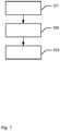
- Fig. 1 shows an example of a flow chart showing the steps of the computer-implemented method of using a dynamic virtual articulator for simulating occlusion of teeth, when performing computer-aided design of one or more dental restorations for a patient.
- step 101 the virtual articulator comprising a virtual three-dimensional model of the upper jaw and a virtual three-dimensional model of the lower jaw resembling the upper jaw and lower jaw, respectively, of the patient's mouth is provided.
- step 102 movement of the virtual upper jaw and the virtual lower jaw relative to each other is provided for simulating dynamic occlusion, whereby collisions between teeth in the virtual upper and virtual lower jaw occur;
- step 103 the teeth in the virtual upper jaw and virtual lower jaw are provided to be blocked from penetrating each other's virtual surfaces in the collisions.
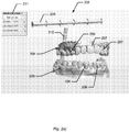
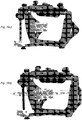
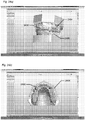
- Fig. 2 shows examples virtual articulators.
- Fig. 2a shows a virtual upper jaw 204 with teeth 206 and a virtual lower jaw 205 with teeth 206.
- Six teeth 207 in the upper jaw 204 have been restored, and the virtual articulator 208 are used to simulate the movements of the jaws 204, 205 to test if the restored teeth 207 fit into the mouth of a patient.
- the virtual articulator 208 is indicated by two axes, an occlusial axis 209 and a laterotrusial-mediotrusial axis 210.
- the jaws 204, 205 moves up and down along the occlusial axis 209, and the jaws 204, 205 performs forward-sidewards movements to both left and right along the laterotrusial-mediotrusial axis 210.
- the jaws 204, 205 can also perform protrusion, which is direct forward movement, and retrusion, which is direct backward movement.
- the axes for these movements are not shown in the figure. In the figure only movement along the occlusial axis 209 is shown, while there is no movement along the laterotrusial-mediotrusial axis 210 or along the protrusial-retrusial axes (not shown).
- Fig. 2b shows another virtual articulator 208 with setting opportunities 209, 210 for controlling the movement of the jaws 204, 205 along an occlusial axis, a laterotrusial-mediotrusial axis, a protrusial-retrusial axis etc.
- the indentations 240 indicate where the dental technician will arrange a default occlusal plane in the form of a rubber band.
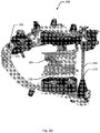
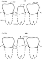
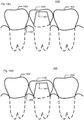
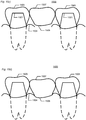
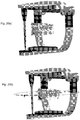
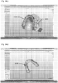
- Fig. 3 shows an example of movements of the jaws for simulating occlusion.
- Both jaws 204, 205 comprise non-modified teeth 206, and the upper jaw 204 also comprises restored teeth 207. The movements are made to simulate, if the restored teeth 207 fit into the mouth.
- Fig. 3a shows the jaws 204, 205 in a first position, where no teeth 206 in the jaws 204, 205 have collided with the restored teeth 207.
- Fig. 3b shows the jaw 204, 205 in a second position, where the jaw 204, 205 have moved closer to each other, but there is still no collision between any of the teeth 206 or the restored teeth 207.
- Fig. 3a shows the jaws 204, 205 in a first position, where no teeth 206 in the jaws 204, 205 have collided with the restored teeth 207.
- Fig. 3b shows the jaw 204, 205 in a second position, where the jaw 204, 205 have moved
- FIG. 3c shows the jaws 204, 205 in a third position, where the jaw 204, 205 have moved even closer to each other.
- Fig. 3d shows the jaws 204, 205 in the third position with a circle 212 at a point 213, where the teeth of the jaws 204, 205 have collided. The collision is between a restored tooth 207a in the upper jaw 204 and a tooth 206a in the lower jaw 205.
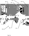
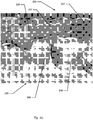
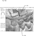
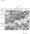
- Fig. 4 shows an example of modelling of a restored tooth.
- Fig. 4a shows the upper jaw 204, turned around relative to the preceding figures, with the restored tooth 207a, another restored tooth 207 and an unmodified tooth 206.
- the restored tooth 207a has collided with a tooth in the lower jaw, as shown in fig. 3d ), and the collision points 214 are indicated on the tooth 207a.
- the shades of the collision points may indicate the penetration depth or the pressure with which the tooth 207a and the tooth in the lower jaw collided.
- the shades from light to dark indicate a depth mapping or pressure mapping, where light shade indicates low depth or light pressure and dark shade indicates large depth or hard pressure.
- the teeth are not completely rigid, but are a little bit soft, and the teeth may therefore give or deform a little when colliding with each other.
- the virtual teeth are not defined to be completely rigid, but are a little bit soft or resilient, and the virtual teeth may therefore give or deform a little when virtually colliding with each other.
- Fig. 4b shows the same as fig. 4a ) and also tools for modelling the restored tooth 207a. Since the tooth 207a collided with a tooth in the lower jaw, see fig. 3d ), the restored 207a) can be modelled such that it will not collide with the tooth in the lower jaw.
- the tooth 207a can be modelled by dragging or morphing it to the left or right side indicated by the tools 215, and by dragging the tooth 207a up and down indicated by the tool 216.
- the tooth 207a can also be modelled by dragging or morphing points on it to the left side or right side indicated by tools 217, and by dragging or morphing it to the neighbour teeth indicated by tools 218.
- the collision points 214 will change corresponding to these shape changes of the tooth, and the tooth 207a can then be modelled such that there will no longer be any collision with the teeth in the lower jaw, and the collisions points 214 will then disappear from the tooth 207a indicating that the tooth 207a has been modelled to avoid collisions with opposing teeth.
- Fig. 5 shows a schematic example of movement along the occlusial axis.
- the figure shows the upper jaw 204 with teeth 206 and the lower jaw 205 with teeth 206. Some of these teeth may be restored teeth, and therefore the occlusion may be tested.
- the occlusial axis 209 is indicated, and the upper jaw 204 is shown to be fixed to the occlusial axis.
- the lower jaw 205 can move relative to the upper jaw 204 and therefore the lower jaw can rotate around the occlusial axis 209.
- the virtual articulator performs collision test and evaluate the response along the occlusial axis 209, i.e. for any given configuration of the other degrees of freedom, i.e. the other axes, see fig.
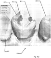
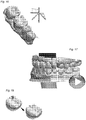
- Fig. 6 shows an example of a virtual model of a set of teeth.
- the virtual model 601 of the set of teeth from a patient comprises a virtual lower arch 602 and a virtual upper arch/jaw 603.
- Six front teeth 604 in the upper arch 603 are marked in a different color than the rest of the teeth 605 of the set of teeth. These six teeth 604 may be teeth which should be or have been restored.
- the virtual model 601 may be shown in a graphical user interface, in which an operator, such as a dental technician or dentist, can design, simulate and/or model for example restorations for a patient.
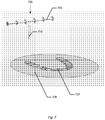
- Fig. 7 shows an example of a virtual occlusal plane.
- the occlusal plane 706 is visualized as a flat, circular plane, but it is understood that the occlusal plane can have any shape etc.
- the occlusal plane is a plane passing through the occlusal or biting surfaces of the teeth, and it represents the mean of the curvature of the occlusal surface. Thus the the occlusal plane can be flat or undulating following the different heights of the different teeth.
- a contour of a standard set of teeth 707 is shown on the occlusal plane 706 for assisting the operator to better match the 3D position of the occlusal surface 706 with a virtual model.
- a virtual articulator 708 is indicated by two axes, an occlusial axis 709 and a laterotrusial-mediotrusial axis 710.
- the upper and lower arches of the virtual model can move up and down along the occlusial axis 709, and the arches can perform forward-sidewards movements to both left and right along the laterotrusial-mediotrusial axis 710.
- the arches can also perform protrusion, which is direct forward movement, and retrusion, which is direct backward movement.
- the axes for these movements are not shown in the figure. The different movement directions possible may be:
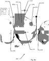
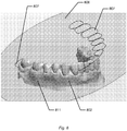
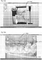
- Fig. 8 shows a first example of a virtual occlusal plane and a virtual model before they are adjusted relative to each other's positions.
- the occlusal plane 806 with the standard set of teeth 807 and the virtual model of the lower arch 802 are shown together.
- the occlusal plane 806 is shown to be inclined relative to the virtual model of the lower arch 802, and the occlusal plane 806 and the virtual model of the lower arch 802 are intersecting each other as seen by the intersection line 811.
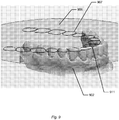
- Fig. 9 shows a second example of a virtual occlusal plane and a virtual model while they are adjusted relative to each other's positions.
- the occlusal plane 906 with the standard set of teeth 907 and the virtual model of the lower arch 902 are shown together.
- the occlusal plane 906 and the virtual model of the lower arch 902 are nearly aligned as their inclinations are the same or almost the same, but the occlusal plane 906 and the virtual model of the lower arch 902 are still intersecting each other a little bit as seen by the intersection line 911 because some of the teeth of the lower arch 902 are a little bit higher than the vertical position of the occlusal plane 906.
- the occlusal plane 906 and the lower arch 902 are not aligned horizontally yet, because the standard set of teeth 907 on the occlusal plane 906 are not overlapping with the teeth of the lower arch 902.
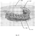
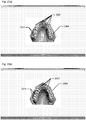
- Fig. 10 shows an example of a virtual occlusal plane and a virtual model after they are adjusted relative to each other's positions.
- the occlusal plane 1006 with the standard set of teeth 1007 and the virtual model of the lower arch 1002 are shown together.
- the occlusal plane 1006 and the virtual model of the lower arch 1002 are aligned as their inclinations are the same, and the occlusal plane 1006 and the virtual model of the lower arch 1002 are still intersecting each other a little bit as seen by the intersection line 1011 because some of the teeth of the lower arch 1002 are a little bit higher than the vertical position of the occlusal plane 1006.
- the occlusal plane 1006 and the lower arch 1002 are aligned horizontally, because the standard set of teeth 1007 on the occlusal plane 1006 are overlapping with the teeth of the lower arch 1002.
- the alignment may be a 3-point alignment, i.e. using three points for performed the alignment.
- Fig. 11 shows an example of a virtual articulator.
- the virtual articulator 1108 is a virtual version of a physical, mechanical device used in dentistry to which casts of the upper and lower teeth are fixed and reproduces recorded positions of the lower teeth in relation to the upper teeth.
- An articulator can be adjustable in one or more of the following areas: condylar angle, Bennett side-shift, incisal and cuspid guidance, and shape of the glenoid fossae and eminintiae.
- An articulator may reproduce normal lower movements during chewing.
- An articulator may be adjusted to accommodate the many movements and positions of the lower teeth in relation to the upper teeth as recorded in the mouth. Thus the virtual articulator may perform all the movements etc. as the mechanical articulator.
- the virtual articulator 1108 comprises a bottom base 1109 onto which the virtual model of the lower teeth or lower jaw is adapted to be arranged, a top base 1110 onto which the virtual model of the upper teeth or upper jaw is adapted to be arranged.
- the different virtual joints, slides or setting means 1111 indicates the joints, slides and other settings of a mechanical articulator where the different areas mentioned above can be adjusted to the features of a specific patient.
- Fig. 12 shows an example of a flow chart of an embodiment of the invention.
- step 1201 the movement of the virtual upper jaw and the virtual lower jaw relative to each other is started.
- step 1202 all collisions during the movement of the virtual upper jaw and the virtual lower jaw relative to each other are registered.
- step 1203 the movement of the virtual upper jaw and the virtual lower jaw relative to each other is finished.
- step 1204 each area of the restorations where a collision point was registered is modelled.
- Fig. 13 shows an example of a movement of the virtual upper jaw and the virtual lower jaw relative to each other.
- Fig. 13a shows the first position of a movement between the upper jaw 1304 and the lower jaw 1305.
- Both the lower jaw and the upper jaw comprise teeth 1306, and the upper jaw comprises a number of restorations 1307.
- Fig. 13b shows a position during the movement of the jaws.
- the upper jaw 1304 is moved relative to the lower jaw 1305, and the restoration 1307 is colliding with a tooth 1306 as seen by the collision point 1314 comprising a contact area.
- Fig. 13c shows the end position of the movement of the jaws, and all the collision points are marked on the teeth and restorations.
- the restoration 1307 can now be modelled by virtually removing or remodelling material from the restoration, whereby the collision in point 1314 will not happen again when the jaws are moved relative to each other, both virtually and in the patient's mouth.
- Fig. 14 shows an example of displacing the position of a prepared tooth for designing the restoration.
- Fig. 14a shows an example of a 3D representation of a set of teeth 1400, where a tooth 1401 has been prepared for a restoration, such as a crown. Two neighbour teeth 1402 are also shown. The toot roots 1403 are indicated.
- the tooth roots 1403 may be derived from a CT scan or may be extrapolated based in a normal 3D scan. Showing the tooth roots 1403 in the 3D representation is optional, since designing a restoration does not require seeing the tooth root, but it may a help for the operator designing the restoration.
- the gingival 1404 is also seen.
- Fig. 14b shows that the preparation 1401 is vertically displaced from its position at the gingival 1404 and from the neighbour teeth to reduce the distance to the antagonist when designing the restoration.
- Fig. 14c shows that a restoration 1405, here in the form of a crown, is designed on the preparation, when the preparation is displaced from the gingival 1404 and the neighbour teeth.
- the restoration is designed in a different occlusion than the normal occlusion of the teeth.
- the upper edge of the restoration 1405 is shown to be substantially flush or level with the two neighbour teeth 1402 when being designed.
- Fig. 14d shows the situation when the preparation 1401 with the restoration 1405 is positioned in its actual position again after designing the restoration 1405. Because the restoration 1405 was designed to be level with the neighbour teeth 1402 when it was displaced, the restoration 1405 is shorter than the neighbour teeth 1402, when it is positioned in its original position again. Thus in the mouth of the patient, the restoration will be shorter than the neighbour teeth, and the restoration, which may be more fragile than the real teeth, is therefore protected better.
- Fig. 15 shows an example of displacing the position of a gingival part for designing the restoration.
- Fig. 15a shows an example of a 3D representation of a set of teeth 1500 with a missing tooth in a region of the gingival 1506.
- the missing tooth may have been broken, died, pulled out due to disease etc.
- a restoration should be made to replace the missing tooth in the region 1506.
- Two neighbour teeth 1502 are also shown.
- the toot roots 1503 are indicated.
- the tooth roots 1503 may be derived from a CT scan or may be extrapolated based in a normal 3D scan. Showing the tooth roots 1503 in the 3D representation is optional, since designing a restoration does not require seeing the tooth root, but it may a help for the operator designing the restoration.
- the gingival 1504 is also seen.
- the restoration to made to replace the missing tooth may be a bridge.
- the bridge may comprise a pontic in the place of the missing tooth and two crowns on the neighbour teeth 1502.
- Fig. 15b shows that the two neighbour teeth have been prepared and are now prepared teeth 1501.
- the region of the gingival 1506 of the missing tooth is displaced from its original position at the gingival.
- Fig. 15c shows that a restoration, here in the form of a bridge, is designed.
- a pontic 1507 is arranged in the place of the missing tooth, and crowns 1505 have been designed on the two preparations 1501.
- the pontic is attached to the crowns.
- the pontic 1507 is designed, when the region of the gingival 1506 is displaced from its original position.
- the upper edge of the pontic 1507 is substantially flush or level with the designed crowns 1505 on the two prepared neighbour teeth 1501.
- Fig. 15d shows the situation when the pontic 1507 and the region of the gingival 1506 is positioned in its actual position again after designing the pontic 1507. Because the pontic 1507 was designed to be level with the crowns 1505 of the neighbour teeth, when it was displaced, the pontic 1507 is shorter than the crowns 1505 neighbour teeth, when the pontic 1507 is positioned in its original position again. Thus in the mouth of the patient, the pontic will be shorter than the crowns of the neighbour teeth, and the pontic, which may be more fragile than the crowns of the neighbour teeth, is therefore protected better.
- Fig. 16 shows an example of an occlusal compass.
- the occlusal compass indicates movements during dynamic occlusion in the following directions:
- Fig. 17 shows an example of playing a recording of the jaw movements.
- the movement of the virtual upper jaw and the virtual lower jaw relative to each other has been recorded, and before and/or after modeling a restoration, the recording can be played to test the modeling.
- a predefined motion sequence may also be played.
- Fig. 18 shows an example of modeling a restoration to compensate for collisions with the opposite teeth.
- Fig. 19 shows examples of virtual articulators resembling physical articulators form different manufacturers.
- Fig. 19a shows an articulator from KaVo.
- Fig. 19b shows an articulator from SAM.
- Fig. 19c shows an articulator from Denar.
- Fig. 19d shows the articulator from Denar with the occlusal plane arranged relative to the virtual teeth model.
- Fig. 20 shows an example of a virtual articulator, which only exists as a virtual articulator.
- Fig. 20a shows a 3Shape virtual articulator. The articulator does not exist as a physical articulator.
- Fig. 20b shows the 3Shape virtual articulator with the occlusal plane arranged relative to the virtual teeth model.
- Fig. 21 shows examples of the traces of movement.
- Fig. 21a shows an example of a first collision point 2114 between an unmodified tooth 2106 and another unmodified tooth or restoration 2107 at time t1.
- Fig. 21b shows an example of a subsequent collision point 2114 between the unmodified tooth 2106 and the other unmodified tooth or restoration 2107 at time t2.
- Fig. 21c shows an example of another subsequent collision point 2114 between the unmodified tooth 2106 and the other unmodified tooth or restoration 2107 at time t3.
- Fig. 21d shows the trace of the motion for the other unmodified tooth or restoration 2107 and the tooth 2106 at the three time instances, t1, t2, t3.
- the trace of the motion between the tooth 2106 and the other unmodified tooth or restoration 2107 is indicated by the arrows 2120.
- the surface of collision points 2114 may be denoted the trace motion, the motion trace surface etc.
- collision surface or trace of collisions points or collision points surface is used for both describing when unmodified teeth are simulated to move relative to each where the teeth collide and do not penetrate each other and for describing when a restoration is simulated relative to unmodified teeth where the restoration may penetrate the unmodified teeth, i.e. the restoration and the unmodified may penetrate each other.
- the simulated collisions or collision surfaces between unmodified teeth may determine the motion which can be performed between the upper and lower teeth models. This determined motion may then be used and studied when designing the restoration.
- Fig. 21e shows the trace 2120 of a motion for a restoration 2107 and a tooth 2106 at the four time instances, t1, t2, t3, t4.
- the motion is shown at the three time instances t1, t2, t3, t4 and time instance lying in between and before and after.
- the restoration 2107 and the tooth 2106 are shown to penetrate each other in the motion.
- the surface of collision or penetration points may be denoted the trace motion 2120.
- the tooth 2106 is shown to move relative to the restoration 2107, however it may be vice versa, i.e. that the restoration 2107 moves relative to the tooth 2107.
- Fig. 22 shows an example of virtual simulation of orthodontic treatment planning.
- Fig. 22a shows a virtual orthodontic model of teeth with an upper model 2204 and a lower model 2205 in a virtual articulator 2208 for simulating the occlusion.
- the simulation of occlusion in the virtual articulator can detect and study malocclusion, and assist and/or determine an orthodontic treatment planning.
- An orthodontic treatment can also be performed for pure cosmetic reasons, if the patient's teeth are arranged aesthetically.
- Fig. 22b shows a zoom-in on the teeth in the virtual models 2204, 2205, where contact areas or collision points 2214 are registered during simulation of the occlusion. The detected contact areas or collision points 2214 can be used in determining the treatment planning to be performed.
- Fig. 23 shows an example of virtual simulation of dental displacement.
- Fig. 23a shows a virtual upper teeth model 2304 of a patient's teeth before orthodontic treatment, where the teeth 2307 are not arranged aesthetically.
- the contact areas or collision point 2314 detected or registered in a virtual articulator simulation are shown on the teeth.
- Fig. 23b shows an example of the virtual upper teeth model 2304 with a suggested final result which can be obtained after displacement of the teeth 2307.
- a patient can decide whether he wish to have the dental displacement performed for obtaining the aesthetic set of front teeth.
- Fig. 24 shows an example of an orthodontic appliance for displacing teeth.
- Fig. 24a shows a virtual upper model 2404 and a virtual lower model 2405, where a virtual orthodontic appliance 2430 in the form of a splint is shown to be arranged in the teeth in the upper model 2404.
- the physical appliance may be worn by a patient on his teeth for treating temporal mandibular dysfunction.
- the appliance 2430 may be virtually designed using a virtual articulator, e.g. as shown in fig. 22a ).
- Fig. 24b shows a top view of the appliance 2430 on the virtual teeth model 2404.
- Fig. 24c shows a perspective side view of the appliance 2430 on the virtual teeth model 2404.
- Fig. 24d shows a bottom view of the appliance 2430.
- the appliance design in figures 24 are the courtesy of and kindly provided by Tridentestense Ortodonzia S.r.l, Italy.
- the features of the method described above and in the following may be implemented in software and carried out on a data processing system or other processing means caused by the execution of computer-executable instructions.
- the instructions may be program code means loaded in a memory, such as a RAM, from a storage medium or from another computer via a computer network.
- the described features may be implemented by hardwired circuitry instead of software or in combination with software.
Claims (13)
- Computer-implementiertes Verfahren zur Verwendung eines dynamischen virtuellen Artikulators (208, 708, 1108, 2208) zum Simulieren der Okklusion von Zähnen (206, 707), beim Ausführen einer Computer-gestützten Planung eines oder mehrerer Zahnrestaurationen (1307) für einen Patienten, wobei das Verfahren die Schritte umfasst von:- Bereitstellen des virtuellen Artikulators (208, 708, 1108, 2208), der ein virtuelles dreidimensionales Modell des Oberkiefers (204, 1304) und ein virtuelles dreidimensionales Modell des Unterkiefers, das dem Oberkiefer (204, 1304) bzw. dem Unterkiefer (205, 1305) des Mundes des Patienten ähnelt, umfasst;- Bereitstellen einer Bewegung des virtuellen Oberkiefers (204, 1304) und des virtuellen Unterkiefers (205, 1305) relativ zueinander zur Simulation einer dynamischen Okklusion, wodurch Kollisionen zwischen Zähnen im virtuellen Ober- und virtuellen Unterkiefer (204, 205, 1304, 1305) auftreten;wobei das Verfahren weiter umfasst:- Vorsehen, dass die Zähne (206, 707) im virtuellen Oberkiefer (204, 1304) und im virtuellen Unterkiefer (205, 1305) bei Kollisionen vor dem Eindringen in die virtuellen Oberflächen des anderen blockiert sind, und wobei die virtuellen Oberflächen der einen oder mehreren Restaurationen (1307) durchdringbar sind.
- Computer-implementiertes Verfahren nach dem vorstehenden Anspruch, wobei das Verfahren weiter die gleichzeitige Modellierung der einen oder mehreren Zahnrestaurationen und die Kollisionsprüfung des virtuellen Oberkiefers und des virtuellen Unterkiefers umfasst.
- Computer-implementiertes Verfahren nach einem der vorstehenden Ansprüche, wobei das Verfahren weiter das Befestigen des virtuellen Oberkiefers an der Okklusalachse umfasst, so dass der virtuelle Unterkiefer konfiguriert ist, sich relativ zum virtuellen Oberkiefer zu bewegen.
- Computer-implementiertes Verfahren nach einem der vorstehenden Ansprüche, wobei das Verfahren weiter umfasst, dass der virtuelle Unterkiefer konfiguriert ist, um sich automatisch durch mindestens einen vordefinierten Bewegungspfad relativ zum virtuellen Oberkiefer zu bewegen.
- Computer-implementiertes Verfahren nach einem der vorstehenden Ansprüche, wobei der Teil der einen oder der mehreren Zahnrestaurationen, der eine Kollision verursacht, konfiguriert ist, automatisch aus dem jeweiligen virtuellen Kiefer entfernt zu werden.
- Computer-implementiertes Verfahren nach einem der vorstehenden Ansprüche, wobei das Verfahren weiter das Positionieren einer virtuellen Ausrichtungsebene in Bezug auf den virtuellen Oberkiefer und den virtuellen Unterkiefer umfasst, wobei der virtuelle Oberkiefer und der virtuelle Unterkiefer ein virtuelles Modell des Zahnsatzes definieren, wobei das Verfahren die Schritte umfasst von:- Visualisieren der virtuellen Ausrichtungsebene und des virtuellen Oberkiefers und des virtuellen Unterkiefers; und- automatisches Positionieren der virtuellen Ausrichtungsebene und des virtuellen Unterkiefers und des virtuellen Oberkiefers relativ zueinander basierend auf einem oder mehreren Parametern.
- Computer-implementiertes Verfahren nach einem der vorstehenden Ansprüche, wobei einer oder mehrere der Parameter von einer Gesichtsbogenmessung des Patienten abgeleitet sind, wobei der Gesichtsbogen eine Bissgabel mit Abdruckmaterial zum Bereitstellen eines Abdrucks des oberen Zahnbogens umfasst, und das Verfahren weiter das Bestimmen der Position und Ausrichtung der Bissgabel in Bezug auf den Gesichtsbogen umfasst, und wobei das Verfahren weiter das Scannen der Bissgabel mit dem Abdruck des oberen Zahnbogens umfasst, um einen Scan des Abdrucks und einen Scan der Bissgabel bereitzustellen.
- Computer-implementiertes Verfahren nach einem der vorstehenden Ansprüche, wobei das Verfahren weiter umfasst, dass während der Bewegung des virtuellen Oberkiefers und des virtuellen Unterkiefers relativ zueinander alle Kollisionen zwischen Zähnen registriert werden und nach Beendigung der Bewegung die Modellierung der Kollisionspunkte der Restaurationen durchgeführt wird.
- Computer-implementiertes Verfahren nach einem oder mehreren der vorstehenden Ansprüche, wobei das Verfahren das Registrieren der Spur der Kollisionsoberfläche und das automatische Schleifen von Zahnmaterial basierend auf der Kollisionsoberfläche umfasst.
- Computer-implementiertes Verfahren nach einem oder mehreren der vorstehenden Ansprüche, wobei ein okklusaler Kompass basierend auf der Okklusionssimulation erzeugt wird.
- Computer-implementiertes Verfahren nach Anspruch 10, wobei der okklusale Kompass Bewegungen mit unterschiedlichen Farben auf den Zähnen in den folgenden Richtungen anzeigt:- Überstand;- Retrusion;- Laterotrusion nach rechts;- Laterotrusion nach links;- Mediotrusion nach rechts;- Mediotrusion nach links;- latero-re Surtrusion nach rechts;- latero-re Surtrusion nach links.
- Computer-implementiertes Verfahren nach einem oder mehreren der vorstehenden Ansprüche, wobei ein CT-Scan des Mundes des Patienten erzeugt wird und ein virtuelles 3D-Modell des Mundes des Patienten automatisch basierend auf dem Scan erzeugt wird und eine Okklusion konfiguriert ist, um basierend auf dem 3D-CT-Modell, simuliert zu werden.
- Computer-implementiertes Verfahren nach einem oder mehreren der vorstehenden Ansprüche, wobei die Bewegung des virtuellen Oberkiefers und des virtuellen Unterkiefers relativ zueinander aufgezeichnet wurde, und vor und/oder nach der Modellierung einer Restauration die Aufzeichnung abgespielt werden kann, um die Modellierung zu testen.
Priority Applications (3)
| Application Number | Priority Date | Filing Date | Title |
|---|---|---|---|
| DK19166764.1T DK3583910T3 (da) | 2010-02-25 | 2011-02-17 | Dynamisk virtuel artikulator |
| EP22172598.9A EP4059471A1 (de) | 2010-02-25 | 2011-02-17 | Dynamischer virtueller artikulator |
| EP19166764.1A EP3583910B1 (de) | 2010-02-25 | 2011-02-17 | Dynamischer virtueller artikulator |
Applications Claiming Priority (7)
| Application Number | Priority Date | Filing Date | Title |
|---|---|---|---|
| US30793410P | 2010-02-25 | 2010-02-25 | |
| DKPA201000156 | 2010-02-25 | ||
| US33468110P | 2010-05-14 | 2010-05-14 | |
| DKPA201000425 | 2010-05-14 | ||
| US38384010P | 2010-09-17 | 2010-09-17 | |
| DKPA201000835 | 2010-09-17 | ||
| PCT/DK2011/050047 WO2011103876A1 (en) | 2010-02-25 | 2011-02-17 | Dynamic virtual articulator |
Related Child Applications (2)
| Application Number | Title | Priority Date | Filing Date |
|---|---|---|---|
| EP19166764.1A Division EP3583910B1 (de) | 2010-02-25 | 2011-02-17 | Dynamischer virtueller artikulator |
| EP22172598.9A Division EP4059471A1 (de) | 2010-02-25 | 2011-02-17 | Dynamischer virtueller artikulator |
Publications (3)
| Publication Number | Publication Date |
|---|---|
| EP2549946A1 EP2549946A1 (de) | 2013-01-30 |
| EP2549946A4 EP2549946A4 (de) | 2013-10-23 |
| EP2549946B1 true EP2549946B1 (de) | 2019-04-03 |
Family
ID=44506138
Family Applications (3)
| Application Number | Title | Priority Date | Filing Date |
|---|---|---|---|
| EP19166764.1A Active EP3583910B1 (de) | 2010-02-25 | 2011-02-17 | Dynamischer virtueller artikulator |
| EP22172598.9A Pending EP4059471A1 (de) | 2010-02-25 | 2011-02-17 | Dynamischer virtueller artikulator |
| EP11746885.0A Active EP2549946B1 (de) | 2010-02-25 | 2011-02-17 | Dynamischer virtueller artikulator |
Family Applications Before (2)
| Application Number | Title | Priority Date | Filing Date |
|---|---|---|---|
| EP19166764.1A Active EP3583910B1 (de) | 2010-02-25 | 2011-02-17 | Dynamischer virtueller artikulator |
| EP22172598.9A Pending EP4059471A1 (de) | 2010-02-25 | 2011-02-17 | Dynamischer virtueller artikulator |
Country Status (12)
| Country | Link |
|---|---|
| US (2) | US20130066598A1 (de) |
| EP (3) | EP3583910B1 (de) |
| JP (1) | JP5859986B2 (de) |
| KR (1) | KR101785586B1 (de) |
| CN (1) | CN102933171B (de) |
| AU (1) | AU2011220162B2 (de) |
| CA (1) | CA2790243C (de) |
| DK (2) | DK2549946T3 (de) |
| ES (1) | ES2925662T3 (de) |
| MX (1) | MX2012009824A (de) |
| RU (1) | RU2567604C2 (de) |
| WO (1) | WO2011103876A1 (de) |
Families Citing this family (101)
| Publication number | Priority date | Publication date | Assignee | Title |
|---|---|---|---|---|
| BR112012021294B1 (pt) | 2010-02-25 | 2021-07-20 | 3Shape A/S | Método implementado por computador de usar um articulador virtual dinâmico para simular oclusão de dentes |
| US9152767B2 (en) * | 2010-03-17 | 2015-10-06 | ClearCorrect Holdings, Inc. | Methods and systems for employing artificial intelligence in automated orthodontic diagnosis and treatment planning |
| US10568716B2 (en) * | 2010-03-17 | 2020-02-25 | ClearCorrect Holdings, Inc. | Methods and systems for employing artificial intelligence in automated orthodontic diagnosis and treatment planning |
| US9788917B2 (en) * | 2010-03-17 | 2017-10-17 | ClearCorrect Holdings, Inc. | Methods and systems for employing artificial intelligence in automated orthodontic diagnosis and treatment planning |
| US9226806B2 (en) * | 2010-09-17 | 2016-01-05 | Biocad Medical, Inc. | Occlusion estimation in dental prosthesis design |
| WO2013002374A1 (ja) * | 2011-06-30 | 2013-01-03 | 株式会社明治 | 嚥下シミュレーション装置及び方法 |
| US10552549B2 (en) * | 2011-10-06 | 2020-02-04 | 3Shape A/S | Virtual design of attachment of dental model in articulator |
| KR101975626B1 (ko) * | 2011-11-15 | 2019-05-07 | 트리스페라 덴탈 아이엔씨. | 3d 모델을 준비하기 위해 개인으로부터 데이터를 획득하기 위한 방법 및 시스템 |
| EP2814421B1 (de) | 2012-02-14 | 2018-04-04 | 3Shape A/S | Modellierung eines digitalen entwurfs einer zahnprothese |
| US10380271B2 (en) * | 2012-02-14 | 2019-08-13 | Ronald G. Presswood | Method and apparatus for dental articulation |
| JP2013169239A (ja) * | 2012-02-17 | 2013-09-02 | Gikou:Kk | 歯科補綴物製造支援装置、歯科補綴物製造支援プログラムおよび歯形データ |
| ES2426019B1 (es) * | 2012-03-16 | 2014-08-22 | Universidad Del Pais Vasco - Euskal Herriko Unibertsitatea | Procedimiento de captación de información para el despliegue virtual y dispositivo asociado al mismo |
| US20130249893A1 (en) * | 2012-03-20 | 2013-09-26 | Tarun Mehra | Virtual aligner |
| JP6022789B2 (ja) * | 2012-03-27 | 2016-11-09 | 株式会社明治 | 嚥下シミュレーション装置及び方法 |
| US8594408B2 (en) * | 2012-04-17 | 2013-11-26 | Poly Virtual Occlusion, LLC | Systems and methods for analyzing dynamic dental occlusions and making dental appliances |
| DE102012104373B4 (de) * | 2012-05-21 | 2019-02-21 | Albert Mehl | Verfahren zur Bewegungssimulation von Kiefern und Rekonstruktion mit virtuellem funktionellem Bissregistrat |
| JP5975731B2 (ja) * | 2012-05-22 | 2016-08-23 | 和田精密歯研株式会社 | 歯冠設計方法、歯冠設計用プログラム、歯冠設計装置、歯冠作製方法、および歯冠作製装置 |
| AU2013276501B2 (en) | 2012-06-15 | 2017-01-19 | Vita Zahnfabrik H. Rauter Gmbh & Co. Kg | Method for preparing a partial or full dental prosthesis |
| DK3473207T3 (da) * | 2012-10-18 | 2022-06-20 | 3Shape As | System og fremgangsmåde til udformning af en dental komponent |
| ES2713550T3 (es) * | 2012-10-18 | 2019-05-22 | 3Shape As | Sistema y procedimiento para diseñar un componente dental |
| US9730768B2 (en) * | 2013-02-22 | 2017-08-15 | Kelly Lucas | CAD-CAM AGP splint—a method of automatically producing or reproducing a customized AGP (anterior guidance package) equipped splint for a patient with/without a severe malocclusion via one time dentist visit |
| DE102013203588A1 (de) * | 2013-03-01 | 2014-09-04 | Sirona Dental Systems Gmbh | Verfahren zur Konstruktion von Zahnoberflächen eines Zahnersatzteils sowie zur Herstellung dentaler Restaurationen |
| EP2964131B1 (de) | 2013-03-08 | 2018-05-16 | Trophy | Okklusionsabbildung mit modellierung eines elastischen schaumstoffs |
| DE102013211154B4 (de) * | 2013-06-14 | 2021-06-10 | Kulzer Gmbh | Verfahren zur Herstellung eines Gebisses |
| DK3024413T3 (da) * | 2013-07-24 | 2021-07-26 | Sirona Dental Systems Gmbh | Bestemmelse af positionen af den kondylære ledakse til oprettelse af en virtuel artikulator |
| DE102013109484B4 (de) * | 2013-08-30 | 2016-09-01 | Roland Althoff | Verfahren zum Einpassen eines Zahnersatzes in eine Reparaturstelle |
| US9655692B2 (en) * | 2013-11-19 | 2017-05-23 | Kelly Wade Lucas | Pre-fabricated anterior guidance package kit for patients having bruxism/clenching habit with or without various malocclusions-II |
| US20160324605A1 (en) * | 2013-12-30 | 2016-11-10 | 3Shape A/S | Method and system for scanning teeth models |
| US9827138B2 (en) | 2014-01-27 | 2017-11-28 | Bruce W. Hultgren | Fabrication of maxillofacial splints |
| CA2940238C (en) | 2014-02-21 | 2023-01-03 | Trispera Dental Inc. | Augmented reality dental design method and system |
| JP2016022228A (ja) * | 2014-07-22 | 2016-02-08 | 高橋 淳 | コンピュータ、コンピュータで実行される方法、及びコンピュータプログラム、並びにフェイスボウ |
| WO2016034672A1 (en) | 2014-09-04 | 2016-03-10 | 3Shape A/S | Facebow and method of using a facebow |
| EP3193773B1 (de) * | 2014-09-19 | 2020-12-02 | Align Technology, Inc. | Dentalvorrichtung mit repositionierenden klemmbackenelementen |
| KR101506476B1 (ko) * | 2014-11-03 | 2015-03-27 | 이진균 | 교정기 제조용 치아 데이터 생성 장치 및 이를 이용하여 투명 교정기를 제작하는 방법 |
| KR101590140B1 (ko) * | 2014-12-11 | 2016-01-29 | 주식회사 디오코 | 다중 방향에서의 치아 교합을 확인하기 위한 3차원 치아 영상 표시 방법, 장치 및 3차원 치아 영상 표시 방법용 컴퓨터 프로그램을 저장한 컴퓨터 판독 가능 저장 매체 |
| US20170360535A1 (en) * | 2014-12-22 | 2017-12-21 | Dental Wings Inc. | Pre-forms and methods for using same in the manufacture of dental prostheses |
| KR101666982B1 (ko) * | 2014-12-31 | 2016-10-19 | 오스템임플란트 주식회사 | 치과용 임플란트 플래닝 방법, 이를 위한 장치 및 이를 기록한 기록매체 |
| KR101883345B1 (ko) * | 2015-05-27 | 2018-08-30 | 주식회사 디오코 | 치아 교정 시뮬레이션 장치에서의 치아 자동 교정 방법, 그 방법이 적용된 치아 교정 시뮬레이션 장치, 및 이를 저장하는 컴퓨터로 판독 가능한 기록 매체 |
| US10610404B2 (en) * | 2015-06-24 | 2020-04-07 | Kelly Lucas | Systems and methods for producing anterior guidance package (AGP) equipped splint |
| FR3038510B1 (fr) * | 2015-07-07 | 2022-03-04 | Panthera Dental Inc | Methode de conception d'une orthese d'avancee mandibulaire, orthese d'avancee mandibulaire et orthese intra-orale |
| CN107427344B (zh) * | 2015-10-21 | 2020-04-10 | 北京大学口腔医学院 | 口腔上下颌关系重建辅助装置、重建方法和装置 |
| CN108601640B (zh) * | 2016-02-02 | 2020-11-06 | 山口荣二 | 肌位3d调节器具和肌位3d调节咬合器 |
| EP3216419B1 (de) * | 2016-03-10 | 2019-06-05 | 3Shape A/S | Verfahren zur digitalen konstruktion eines zahnersatzes |
| US11317998B2 (en) * | 2016-04-11 | 2022-05-03 | 3Shape A/S | Method for aligning digital representations of a patient's jaws |
| KR101840444B1 (ko) * | 2016-05-04 | 2018-03-20 | 주식회사 메디트 | 치과용 3차원 데이터 처리장치 및 그 방법 |
| KR101802917B1 (ko) * | 2016-05-04 | 2017-11-29 | 주식회사 메디트 | 치아 움직임 추적 장치 및 그 방법 |
| WO2017201572A1 (en) * | 2016-05-23 | 2017-11-30 | Jessi Lew Pty Limited | Methods and apparatus for digital imaging of dental models |
| CN107510511A (zh) * | 2016-06-17 | 2017-12-26 | 刘洋 | 一种颞下颌关节正畸系统及其制作个性化矫治器的方法 |
| KR101794561B1 (ko) * | 2016-06-22 | 2017-11-07 | 주식회사 메디트 | 치아모델 교합용 장치 및 이를 이용한 교합방법 |
| US10304190B2 (en) * | 2016-06-29 | 2019-05-28 | 3M Innovative Properties Company | Virtual model of articulation from intra-oral scans |
| US10507087B2 (en) | 2016-07-27 | 2019-12-17 | Align Technology, Inc. | Methods and apparatuses for forming a three-dimensional volumetric model of a subject's teeth |
| EP3295893A1 (de) | 2016-09-16 | 2018-03-21 | GC Europe N.V. | Verfahren zur erzeugung eines virtuellen oberkiefermodells oder eines unterkiefermodells in einem virtuellen artikulator |
| US10751152B2 (en) * | 2016-12-21 | 2020-08-25 | National Yang-Ming University | Jaw motion tracking system and operating method using the same |
| US10052180B1 (en) | 2016-12-29 | 2018-08-21 | David D. Richter | Virtual dental articulator and system |
| JP2018117837A (ja) | 2017-01-25 | 2018-08-02 | 富士通株式会社 | 咬合状態特定コンピュータプログラム、咬合状態特定装置、及びその方法 |
| JP2018117865A (ja) * | 2017-01-25 | 2018-08-02 | 富士通株式会社 | 移動回転情報生成コンピュータプログラム、移動回転情報生成装置、及びその方法 |
| KR102019164B1 (ko) * | 2017-04-06 | 2019-11-04 | 정연호 | 치아 교정용 와이어 벤딩 경로 생성 방법 |
| US10492892B2 (en) * | 2017-05-17 | 2019-12-03 | 3M Innovative Properties Company | Automatic alignment and orientation of digital 3D dental arch pairs |
| US20200093583A1 (en) * | 2017-06-09 | 2020-03-26 | Eiji Yamaguchi | Occlusion recording instrument and articulator |
| KR102005925B1 (ko) * | 2017-07-10 | 2019-07-31 | 이우형 | 디지털 삼차원 치아모형의 위치 병합이 가능하도록 기준선이 있는 치과용 시스템 |
| WO2019018322A1 (en) * | 2017-07-17 | 2019-01-24 | Board Of Regents, The University Of Texas System | APPARATUS AND METHODS FOR THREE-DIMENSIONAL PRINTED ORAL STOPS FOR HEAD AND NECK RADIATION THERAPY |
| WO2019036514A1 (en) * | 2017-08-17 | 2019-02-21 | Align Technology, Inc. | SYSTEMS, METHODS AND APPARATUS FOR CORRECTING DENTAL MALOCCLUSIONS |
| RU2652014C1 (ru) * | 2017-09-20 | 2018-04-24 | Общество с ограниченной ответственностью "Авантис3Д" | Способ использования динамического виртуального артикулятора для имитационного моделирования окклюзии при выполнении проектирования стоматологических протезов для пациента и носитель информации |
| EA201700561A1 (ru) | 2017-11-16 | 2019-05-31 | Общество С Ограниченной Ответственностью "Доммар" | Способ и система выравнивания зубов на основании моделирования движения коронок и корней |
| KR102040099B1 (ko) * | 2017-12-04 | 2019-12-05 | 울산대학교 산학협력단 | 임플란트 식립영역 선정 장치 및 방법 |
| AU2019212649A1 (en) | 2018-01-26 | 2020-07-02 | Align Technology, Inc. | Diagnostic intraoral scanning and tracking |
| CN108389488B (zh) * | 2018-03-05 | 2020-12-15 | 泉州医学高等专科学校 | 一种互动式口腔模拟系统 |
| CN110353852B (zh) * | 2018-04-10 | 2022-02-01 | 无锡时代天使医疗器械科技有限公司 | 基于计算机的测量两颗牙齿间位置关系的方法 |
| CN108836534A (zh) * | 2018-06-21 | 2018-11-20 | 四川大学 | 一种基于3d打印的前牙咬合阻断器的制作及使用方法 |
| US20210353394A1 (en) * | 2018-11-01 | 2021-11-18 | Woo Hyoung Lee | Digital three-dimensional tooth model system |
| JP2022515432A (ja) * | 2018-12-26 | 2022-02-18 | スリーエム イノベイティブ プロパティズ カンパニー | デジタルメッシュオブジェクト間の衝突を自動的に除去し、メッシュオブジェクトを空間的配置間で滑らかに移動させる方法 |
| EP3698754B1 (de) * | 2019-02-19 | 2022-10-05 | DENTSPLY SIRONA Inc. | Verfahren zur messung der patientenspezifischen kiefergelenkverbindung und übertragung davon in einen virtuellen artikulator |
| WO2020171314A1 (ko) * | 2019-02-21 | 2020-08-27 | 주식회사 디오 | 스캔용 왁스바이트 및 이를 이용한 치아 수복물 제조방법 |
| KR102129526B1 (ko) * | 2019-03-12 | 2020-07-02 | 주식회사 키스톤 | 3d 데이터로 형성된 교합정보를 실물 교합기에 옮기기 위한 3d 프린팅 커넥터 제작 시스템 및 그 제작방법 |
| WO2020191017A1 (en) * | 2019-03-21 | 2020-09-24 | Bruce Willard Hultgren | Motion adjustment prediction system |
| US11000349B2 (en) * | 2019-06-05 | 2021-05-11 | Dentsply Sirona Inc. | Method, system and computer readable storage media for determining articulation parameters |
| JP7170933B2 (ja) | 2019-07-18 | 2022-11-14 | スリーエム イノベイティブ プロパティズ カンパニー | 歯科治療のための仮想咬合モデル |
| WO2021009733A1 (en) * | 2019-07-18 | 2021-01-21 | 3M Innovative Properties Company | Virtual articulation in orthodontic and dental treatment planning |
| KR102085779B1 (ko) * | 2019-11-11 | 2020-03-06 | 정다이 | 맞춤형 코골이 및 수면무호흡 방지 장치의 제작 장치 |
| CN110815493B (zh) * | 2019-11-28 | 2021-03-23 | 四川大学 | 一种基于3d模型且用于前牙修复的导板制作方法 |
| US10695146B1 (en) | 2019-12-04 | 2020-06-30 | Oxilio Ltd | Systems and methods for determining orthodontic treatments |
| KR20210088946A (ko) * | 2020-01-07 | 2021-07-15 | 주식회사 메디트 | 데이터 정합을 통한 3차원 모델 생성 장치 및 방법 |
| WO2021216349A1 (en) * | 2020-04-20 | 2021-10-28 | The Regents Of The University Of Michigan | Methods and systems for obtaining hinge axis position and condyle guide inclination from a patient |
| KR102410043B1 (ko) * | 2020-04-28 | 2022-06-21 | 오스템임플란트 주식회사 | 대상체에 대한 스캔 데이터를 획득하는 디바이스 및 방법 |
| CN111759506B (zh) * | 2020-07-23 | 2021-12-07 | 茵伯特(上海)医疗技术有限公司 | 一种种植牙全数字化种植修复方法及系统 |
| CN111956347B (zh) * | 2020-08-03 | 2022-03-18 | 厦门医学院附属口腔医院(厦门市口腔医院) | 颞下颌关节髁突发育诱导器及其制备方法 |
| US20220061957A1 (en) * | 2020-08-31 | 2022-03-03 | James R. Glidewell Dental Ceramics, Inc. | Automatic bite setting |
| CN112022384B (zh) * | 2020-09-04 | 2022-12-06 | 上海交通大学医学院附属第九人民医院 | 基于cad/cam的数字化树脂板、制备方法及应用 |
| KR102575832B1 (ko) * | 2020-10-06 | 2023-09-11 | 이우형 | 상하악 치열의 악궁 형태 및 교합 양상을 분류한 빅데이터 클라우드를 기반으로 한 악궁 형태, 교합양상을 분석할 수 있고, 해부학적 이상적인 위치에 상하악 치열이 병합될 수 있는 시스템 |
| KR102498809B1 (ko) * | 2020-10-23 | 2023-02-09 | 사회복지법인 삼성생명공익재단 | 치아교합시뮬레이션 방법 및 시스템 |
| US20240008966A1 (en) * | 2020-11-13 | 2024-01-11 | Medit Corp. | Occlusion alignment method and occlusion alignment apparatus |
| CN112754701B (zh) * | 2021-01-13 | 2022-04-08 | 北京大学口腔医学院 | 支撑装置、架系统及架校准方法 |
| KR102487344B1 (ko) * | 2021-02-18 | 2023-01-11 | 오스템임플란트 주식회사 | 정적 및 동적 교합 데이터를 이용하는 가상 교합 시스템 및 그 동작 방법 |
| KR102538681B1 (ko) * | 2021-02-18 | 2023-05-31 | 오스템임플란트 주식회사 | 무치악 환자의 데이터를 이용하는 치아 배열 시스템 및 그 동작 방법 |
| US20220280264A1 (en) * | 2021-03-05 | 2022-09-08 | YOAT Corporation | Method for generating bending path of orthodontic wire |
| CN113040952B (zh) * | 2021-03-09 | 2022-03-11 | 重庆医科大学附属口腔医院 | 一种个性化确定下颌运动轨迹的方法 |
| US11191619B1 (en) | 2021-05-13 | 2021-12-07 | Oxilio Ltd | Methods and systems for determining occlusal contacts between teeth of a subject |
| US11213373B1 (en) * | 2021-05-14 | 2022-01-04 | Oxilio Ltd | Methods and systems for modeling mandibular motion |
| CN113362955B (zh) * | 2021-06-18 | 2023-09-29 | 北京联袂义齿技术有限公司 | 一种牙颌运动轨迹的建模及评价方法 |
| KR102615021B1 (ko) * | 2021-10-14 | 2023-12-20 | 주식회사 메디트 | 3차원 스캐너의 스캔 이미지 정렬 방법, 장치 및 명령을 기록한 기록매체 |
| CN114343906B (zh) * | 2022-01-07 | 2022-11-08 | 同济大学 | 咬合垂直距离的获取方法、装置、介质及电子设备 |
Family Cites Families (22)
| Publication number | Priority date | Publication date | Assignee | Title |
|---|---|---|---|---|
| TW308330U (en) * | 1996-04-18 | 1997-06-11 | Chuntex Electronic Co Ltd | Rubber/plastic machine with foldable stairway |
| US5975893A (en) * | 1997-06-20 | 1999-11-02 | Align Technology, Inc. | Method and system for incrementally moving teeth |
| US6152731A (en) | 1997-09-22 | 2000-11-28 | 3M Innovative Properties Company | Methods for use in dental articulation |
| US6406292B1 (en) * | 1999-05-13 | 2002-06-18 | Align Technology, Inc. | System for determining final position of teeth |
| US7160110B2 (en) * | 1999-11-30 | 2007-01-09 | Orametrix, Inc. | Three-dimensional occlusal and interproximal contact detection and display using virtual tooth models |
| US8021147B2 (en) * | 2001-04-13 | 2011-09-20 | Orametrix, Inc. | Method and system for comprehensive evaluation of orthodontic care using unified workstation |
| CA2350849A1 (fr) * | 2001-06-15 | 2002-12-15 | Dentalmatic Technologies Inc. | Articulateur virtuel |
| US7361018B2 (en) * | 2003-05-02 | 2008-04-22 | Orametrix, Inc. | Method and system for enhanced orthodontic treatment planning |
| US20060003292A1 (en) * | 2004-05-24 | 2006-01-05 | Lauren Mark D | Digital manufacturing of removable oral appliances |
| US20070031774A1 (en) | 2005-08-03 | 2007-02-08 | 3M Innovative Properties Company | Registering physical and virtual tooth structures with markers |
| US7806687B2 (en) | 2005-08-19 | 2010-10-05 | National University Corporation Okayama University | Occlusal state correction-supporting apparatus, program, and recording medium |
| US7813591B2 (en) | 2006-01-20 | 2010-10-12 | 3M Innovative Properties Company | Visual feedback of 3D scan parameters |
| US20090068617A1 (en) * | 2006-03-03 | 2009-03-12 | Lauren Mark D | Method Of Designing Dental Devices Using Four-Dimensional Data |
| US20070207441A1 (en) | 2006-03-03 | 2007-09-06 | Lauren Mark D | Four dimensional modeling of jaw and tooth dynamics |
| DE102007014088A1 (de) | 2007-03-21 | 2008-09-25 | Dreve Prodimed Gmbh | Verfahren zur generativen Herstellung von individuellen, dentalen Formen für Artikulatoren |
| US9675431B2 (en) * | 2007-08-21 | 2017-06-13 | Sirona Dental Systems Gmbh | Method for designing a plurality of adjacent tooth restorations using CAD/CAM technology |
| JPWO2009035142A1 (ja) * | 2007-09-13 | 2010-12-24 | 株式会社アドバンス | 歯科補綴物計測加工システム |
| US20100332253A1 (en) * | 2008-02-22 | 2010-12-30 | Prasad Adusimilli | Systems and Methods for Providing Customized Dentures |
| GB0807754D0 (en) | 2008-04-29 | 2008-06-04 | Materialise Dental Nv | Method to determine the impact of a prposed dental modification on the temporomandobular joint |
| JP5233456B2 (ja) * | 2008-07-14 | 2013-07-10 | 和田精密歯研株式会社 | 歯冠設計方法および歯冠作製方法 |
| WO2011041530A1 (en) * | 2009-10-01 | 2011-04-07 | The Trustees Of Columbia University In The City Of New York | Dental diagnostic and dental restoration methods, systems, apparatuses, and devices |
| BR112012021294B1 (pt) | 2010-02-25 | 2021-07-20 | 3Shape A/S | Método implementado por computador de usar um articulador virtual dinâmico para simular oclusão de dentes |
-
2011
- 2011-02-17 EP EP19166764.1A patent/EP3583910B1/de active Active
- 2011-02-17 JP JP2012554216A patent/JP5859986B2/ja active Active
- 2011-02-17 AU AU2011220162A patent/AU2011220162B2/en not_active Ceased
- 2011-02-17 DK DK11746885.0T patent/DK2549946T3/da active
- 2011-02-17 US US13/580,876 patent/US20130066598A1/en not_active Abandoned
- 2011-02-17 WO PCT/DK2011/050047 patent/WO2011103876A1/en active Application Filing
- 2011-02-17 RU RU2012139477/14A patent/RU2567604C2/ru active
- 2011-02-17 DK DK19166764.1T patent/DK3583910T3/da active
- 2011-02-17 CN CN201180020930.8A patent/CN102933171B/zh active Active
- 2011-02-17 ES ES19166764T patent/ES2925662T3/es active Active
- 2011-02-17 CA CA2790243A patent/CA2790243C/en active Active
- 2011-02-17 EP EP22172598.9A patent/EP4059471A1/de active Pending
- 2011-02-17 EP EP11746885.0A patent/EP2549946B1/de active Active
- 2011-02-17 KR KR1020127025169A patent/KR101785586B1/ko active IP Right Grant
- 2011-02-17 MX MX2012009824A patent/MX2012009824A/es not_active Application Discontinuation
-
2019
- 2019-03-13 US US16/352,320 patent/US11751981B2/en active Active
Non-Patent Citations (1)
| Title |
|---|
| None * |
Also Published As
| Publication number | Publication date |
|---|---|
| CN102933171B (zh) | 2016-01-13 |
| DK3583910T3 (da) | 2022-09-05 |
| EP4059471A1 (de) | 2022-09-21 |
| US20190216580A1 (en) | 2019-07-18 |
| DK2549946T3 (da) | 2019-05-20 |
| RU2567604C2 (ru) | 2015-11-10 |
| JP2013520251A (ja) | 2013-06-06 |
| US20130066598A1 (en) | 2013-03-14 |
| EP2549946A1 (de) | 2013-01-30 |
| KR101785586B1 (ko) | 2017-10-16 |
| CA2790243C (en) | 2019-03-26 |
| CN102933171A (zh) | 2013-02-13 |
| AU2011220162A1 (en) | 2012-09-13 |
| EP3583910A1 (de) | 2019-12-25 |
| RU2012139477A (ru) | 2014-03-27 |
| WO2011103876A1 (en) | 2011-09-01 |
| KR20130048202A (ko) | 2013-05-09 |
| US11751981B2 (en) | 2023-09-12 |
| EP2549946A4 (de) | 2013-10-23 |
| AU2011220162B2 (en) | 2016-02-11 |
| MX2012009824A (es) | 2013-05-06 |
| JP5859986B2 (ja) | 2016-02-16 |
| ES2925662T3 (es) | 2022-10-19 |
| CA2790243A1 (en) | 2011-09-01 |
| EP3583910B1 (de) | 2022-06-08 |
Similar Documents
| Publication | Publication Date | Title |
|---|---|---|
| US11751981B2 (en) | Dynamic virtual articulator for simulating occlusion of teeth | |
| US11633265B2 (en) | Dynamic virtual articulator for simulating occlusion of teeth | |
| EP2908767B1 (de) | System und verfahren zur entwicklung einer zahnkomponente | |
| US8043091B2 (en) | Computer machined dental tooth system and method | |
| EP2134290B1 (de) | Computergestützte erstellung der zahnstruktur eines individuums über gesichtsanalyse | |
| KR101799878B1 (ko) | 2d 영상 장치 | |
| EP2763622B1 (de) | Virtuelles design der befestigung eines dentalen models an einem artikulator | |
| CN106137414B (zh) | 确定目标牙列布局的方法和系统 | |
| WO2012140021A2 (en) | Modeling and manufacturing orthodontic appliances | |
| US20090068617A1 (en) | Method Of Designing Dental Devices Using Four-Dimensional Data | |
| US20070207441A1 (en) | Four dimensional modeling of jaw and tooth dynamics | |
| PL235136B1 (pl) | Sposób rejestracji ruchu i geometrii stawu skroniowo-żuchwowego | |
| CN113347943A (zh) | 用于对患者的处于矫正颌间关系的下颌弓和上颌弓的模型进行动画处理的方法 | |
| WO2023009732A1 (en) | Computer-implemented method and system for tooth setup | |
| US20240033061A1 (en) | Digital denture design and replacement | |
| KR102144369B1 (ko) | 동명 치아 특성을 이용하는 치과용 캐드 장치 및 그 구동방법 | |
| KR102472029B1 (ko) | 가상 교합기를 제공하는 디바이스 및 방법 | |
| WO2009091438A1 (en) | Method of designing dental devices using four-dimensional data |
Legal Events
| Date | Code | Title | Description |
|---|---|---|---|
| PUAI | Public reference made under article 153(3) epc to a published international application that has entered the european phase |
Free format text: ORIGINAL CODE: 0009012 |
|
| 17P | Request for examination filed |
Effective date: 20120921 |
|
| AK | Designated contracting states |
Kind code of ref document: A1 Designated state(s): AL AT BE BG CH CY CZ DE DK EE ES FI FR GB GR HR HU IE IS IT LI LT LU LV MC MK MT NL NO PL PT RO RS SE SI SK SM TR |
|
| A4 | Supplementary search report drawn up and despatched |
Effective date: 20130923 |
|
| RIC1 | Information provided on ipc code assigned before grant |
Ipc: A61C 19/05 20060101ALI20130917BHEP Ipc: A61C 11/00 20060101ALI20130917BHEP Ipc: A61C 13/00 20060101AFI20130917BHEP Ipc: A61C 19/045 20060101ALN20130917BHEP |
|
| STAA | Information on the status of an ep patent application or granted ep patent |
Free format text: STATUS: EXAMINATION IS IN PROGRESS |
|
| 17Q | First examination report despatched |
Effective date: 20170829 |
|
| RIC1 | Information provided on ipc code assigned before grant |
Ipc: A61C 11/00 20060101ALI20180816BHEP Ipc: A61C 13/00 20060101AFI20180816BHEP Ipc: A61C 19/045 20060101ALN20180816BHEP Ipc: A61C 19/05 20060101ALI20180816BHEP |
|
| GRAP | Despatch of communication of intention to grant a patent |
Free format text: ORIGINAL CODE: EPIDOSNIGR1 |
|
| STAA | Information on the status of an ep patent application or granted ep patent |
Free format text: STATUS: GRANT OF PATENT IS INTENDED |
|
| RIC1 | Information provided on ipc code assigned before grant |
Ipc: A61C 19/045 20060101ALN20180820BHEP Ipc: A61C 13/00 20060101AFI20180820BHEP Ipc: A61C 11/00 20060101ALI20180820BHEP Ipc: A61C 19/05 20060101ALI20180820BHEP |
|
| INTG | Intention to grant announced |
Effective date: 20180921 |
|
| GRAS | Grant fee paid |
Free format text: ORIGINAL CODE: EPIDOSNIGR3 |
|
| GRAA | (expected) grant |
Free format text: ORIGINAL CODE: 0009210 |
|
| STAA | Information on the status of an ep patent application or granted ep patent |
Free format text: STATUS: THE PATENT HAS BEEN GRANTED |
|
| AK | Designated contracting states |
Kind code of ref document: B1 Designated state(s): AL AT BE BG CH CY CZ DE DK EE ES FI FR GB GR HR HU IE IS IT LI LT LU LV MC MK MT NL NO PL PT RO RS SE SI SK SM TR |
|
| REG | Reference to a national code |
Ref country code: GB Ref legal event code: FG4D |
|
| REG | Reference to a national code |
Ref country code: CH Ref legal event code: EP Ref country code: AT Ref legal event code: REF Ref document number: 1114801 Country of ref document: AT Kind code of ref document: T Effective date: 20190415 |
|
| REG | Reference to a national code |
Ref country code: DE Ref legal event code: R096 Ref document number: 602011057758 Country of ref document: DE |
|
| REG | Reference to a national code |
Ref country code: IE Ref legal event code: FG4D |
|
| REG | Reference to a national code |
Ref country code: DK Ref legal event code: T3 Effective date: 20190516 |
|
| REG | Reference to a national code |
Ref country code: NL Ref legal event code: FP |
|
| REG | Reference to a national code |
Ref country code: SE Ref legal event code: TRGR |
|
| REG | Reference to a national code |
Ref country code: CH Ref legal event code: NV Representative=s name: VALIPAT S.A. C/O BOVARD SA NEUCHATEL, CH |
|
| REG | Reference to a national code |
Ref country code: ES Ref legal event code: FG2A Ref document number: 2721878 Country of ref document: ES Kind code of ref document: T3 Effective date: 20190806 |
|
| REG | Reference to a national code |
Ref country code: LT Ref legal event code: MG4D |
|
| REG | Reference to a national code |
Ref country code: AT Ref legal event code: MK05 Ref document number: 1114801 Country of ref document: AT Kind code of ref document: T Effective date: 20190403 |
|
| PG25 | Lapsed in a contracting state [announced via postgrant information from national office to epo] |
Ref country code: FI Free format text: LAPSE BECAUSE OF FAILURE TO SUBMIT A TRANSLATION OF THE DESCRIPTION OR TO PAY THE FEE WITHIN THE PRESCRIBED TIME-LIMIT Effective date: 20190403 Ref country code: LT Free format text: LAPSE BECAUSE OF FAILURE TO SUBMIT A TRANSLATION OF THE DESCRIPTION OR TO PAY THE FEE WITHIN THE PRESCRIBED TIME-LIMIT Effective date: 20190403 Ref country code: HR Free format text: LAPSE BECAUSE OF FAILURE TO SUBMIT A TRANSLATION OF THE DESCRIPTION OR TO PAY THE FEE WITHIN THE PRESCRIBED TIME-LIMIT Effective date: 20190403 Ref country code: NO Free format text: LAPSE BECAUSE OF FAILURE TO SUBMIT A TRANSLATION OF THE DESCRIPTION OR TO PAY THE FEE WITHIN THE PRESCRIBED TIME-LIMIT Effective date: 20190703 Ref country code: PT Free format text: LAPSE BECAUSE OF FAILURE TO SUBMIT A TRANSLATION OF THE DESCRIPTION OR TO PAY THE FEE WITHIN THE PRESCRIBED TIME-LIMIT Effective date: 20190803 Ref country code: AL Free format text: LAPSE BECAUSE OF FAILURE TO SUBMIT A TRANSLATION OF THE DESCRIPTION OR TO PAY THE FEE WITHIN THE PRESCRIBED TIME-LIMIT Effective date: 20190403 Ref country code: CZ Free format text: LAPSE BECAUSE OF FAILURE TO SUBMIT A TRANSLATION OF THE DESCRIPTION OR TO PAY THE FEE WITHIN THE PRESCRIBED TIME-LIMIT Effective date: 20190403 |
|
| PG25 | Lapsed in a contracting state [announced via postgrant information from national office to epo] |
Ref country code: BG Free format text: LAPSE BECAUSE OF FAILURE TO SUBMIT A TRANSLATION OF THE DESCRIPTION OR TO PAY THE FEE WITHIN THE PRESCRIBED TIME-LIMIT Effective date: 20190703 Ref country code: RS Free format text: LAPSE BECAUSE OF FAILURE TO SUBMIT A TRANSLATION OF THE DESCRIPTION OR TO PAY THE FEE WITHIN THE PRESCRIBED TIME-LIMIT Effective date: 20190403 Ref country code: PL Free format text: LAPSE BECAUSE OF FAILURE TO SUBMIT A TRANSLATION OF THE DESCRIPTION OR TO PAY THE FEE WITHIN THE PRESCRIBED TIME-LIMIT Effective date: 20190403 Ref country code: LV Free format text: LAPSE BECAUSE OF FAILURE TO SUBMIT A TRANSLATION OF THE DESCRIPTION OR TO PAY THE FEE WITHIN THE PRESCRIBED TIME-LIMIT Effective date: 20190403 Ref country code: GR Free format text: LAPSE BECAUSE OF FAILURE TO SUBMIT A TRANSLATION OF THE DESCRIPTION OR TO PAY THE FEE WITHIN THE PRESCRIBED TIME-LIMIT Effective date: 20190704 |
|
| PG25 | Lapsed in a contracting state [announced via postgrant information from national office to epo] |
Ref country code: AT Free format text: LAPSE BECAUSE OF FAILURE TO SUBMIT A TRANSLATION OF THE DESCRIPTION OR TO PAY THE FEE WITHIN THE PRESCRIBED TIME-LIMIT Effective date: 20190403 Ref country code: IS Free format text: LAPSE BECAUSE OF FAILURE TO SUBMIT A TRANSLATION OF THE DESCRIPTION OR TO PAY THE FEE WITHIN THE PRESCRIBED TIME-LIMIT Effective date: 20190803 |
|
| REG | Reference to a national code |
Ref country code: DE Ref legal event code: R097 Ref document number: 602011057758 Country of ref document: DE |
|
| PG25 | Lapsed in a contracting state [announced via postgrant information from national office to epo] |
Ref country code: SK Free format text: LAPSE BECAUSE OF FAILURE TO SUBMIT A TRANSLATION OF THE DESCRIPTION OR TO PAY THE FEE WITHIN THE PRESCRIBED TIME-LIMIT Effective date: 20190403 Ref country code: RO Free format text: LAPSE BECAUSE OF FAILURE TO SUBMIT A TRANSLATION OF THE DESCRIPTION OR TO PAY THE FEE WITHIN THE PRESCRIBED TIME-LIMIT Effective date: 20190403 Ref country code: EE Free format text: LAPSE BECAUSE OF FAILURE TO SUBMIT A TRANSLATION OF THE DESCRIPTION OR TO PAY THE FEE WITHIN THE PRESCRIBED TIME-LIMIT Effective date: 20190403 |
|
| PLBE | No opposition filed within time limit |
Free format text: ORIGINAL CODE: 0009261 |
|
| STAA | Information on the status of an ep patent application or granted ep patent |
Free format text: STATUS: NO OPPOSITION FILED WITHIN TIME LIMIT |
|
| PG25 | Lapsed in a contracting state [announced via postgrant information from national office to epo] |
Ref country code: SM Free format text: LAPSE BECAUSE OF FAILURE TO SUBMIT A TRANSLATION OF THE DESCRIPTION OR TO PAY THE FEE WITHIN THE PRESCRIBED TIME-LIMIT Effective date: 20190403 |
|
| 26N | No opposition filed |
Effective date: 20200106 |
|
| PG25 | Lapsed in a contracting state [announced via postgrant information from national office to epo] |
Ref country code: TR Free format text: LAPSE BECAUSE OF FAILURE TO SUBMIT A TRANSLATION OF THE DESCRIPTION OR TO PAY THE FEE WITHIN THE PRESCRIBED TIME-LIMIT Effective date: 20190403 |
|
| PG25 | Lapsed in a contracting state [announced via postgrant information from national office to epo] |
Ref country code: SI Free format text: LAPSE BECAUSE OF FAILURE TO SUBMIT A TRANSLATION OF THE DESCRIPTION OR TO PAY THE FEE WITHIN THE PRESCRIBED TIME-LIMIT Effective date: 20190403 |
|
| REG | Reference to a national code |
Ref country code: BE Ref legal event code: MM Effective date: 20200229 |
|
| PG25 | Lapsed in a contracting state [announced via postgrant information from national office to epo] |
Ref country code: LU Free format text: LAPSE BECAUSE OF NON-PAYMENT OF DUE FEES Effective date: 20200217 Ref country code: MC Free format text: LAPSE BECAUSE OF FAILURE TO SUBMIT A TRANSLATION OF THE DESCRIPTION OR TO PAY THE FEE WITHIN THE PRESCRIBED TIME-LIMIT Effective date: 20190403 |
|
| PG25 | Lapsed in a contracting state [announced via postgrant information from national office to epo] |
Ref country code: IE Free format text: LAPSE BECAUSE OF NON-PAYMENT OF DUE FEES Effective date: 20200217 |
|
| PG25 | Lapsed in a contracting state [announced via postgrant information from national office to epo] |
Ref country code: BE Free format text: LAPSE BECAUSE OF NON-PAYMENT OF DUE FEES Effective date: 20200229 |
|
| PGFP | Annual fee paid to national office [announced via postgrant information from national office to epo] |
Ref country code: DK Payment date: 20220218 Year of fee payment: 12 Ref country code: CH Payment date: 20220216 Year of fee payment: 12 |
|
| PG25 | Lapsed in a contracting state [announced via postgrant information from national office to epo] |
Ref country code: MT Free format text: LAPSE BECAUSE OF FAILURE TO SUBMIT A TRANSLATION OF THE DESCRIPTION OR TO PAY THE FEE WITHIN THE PRESCRIBED TIME-LIMIT Effective date: 20190403 Ref country code: CY Free format text: LAPSE BECAUSE OF FAILURE TO SUBMIT A TRANSLATION OF THE DESCRIPTION OR TO PAY THE FEE WITHIN THE PRESCRIBED TIME-LIMIT Effective date: 20190403 |
|
| PGFP | Annual fee paid to national office [announced via postgrant information from national office to epo] |
Ref country code: SE Payment date: 20220216 Year of fee payment: 12 Ref country code: NL Payment date: 20220216 Year of fee payment: 12 |
|
| PG25 | Lapsed in a contracting state [announced via postgrant information from national office to epo] |
Ref country code: MK Free format text: LAPSE BECAUSE OF FAILURE TO SUBMIT A TRANSLATION OF THE DESCRIPTION OR TO PAY THE FEE WITHIN THE PRESCRIBED TIME-LIMIT Effective date: 20190403 |
|
| PGFP | Annual fee paid to national office [announced via postgrant information from national office to epo] |
Ref country code: FR Payment date: 20230221 Year of fee payment: 13 |
|
| PGFP | Annual fee paid to national office [announced via postgrant information from national office to epo] |
Ref country code: IT Payment date: 20230223 Year of fee payment: 13 Ref country code: GB Payment date: 20230220 Year of fee payment: 13 Ref country code: DE Payment date: 20230216 Year of fee payment: 13 |
|
| P01 | Opt-out of the competence of the unified patent court (upc) registered |
Effective date: 20230529 |
|
| PGFP | Annual fee paid to national office [announced via postgrant information from national office to epo] |
Ref country code: ES Payment date: 20230426 Year of fee payment: 13 |
|
| REG | Reference to a national code |
Ref country code: DK Ref legal event code: EBP Effective date: 20230228 |
|
| REG | Reference to a national code |
Ref country code: CH Ref legal event code: PL |
|
| REG | Reference to a national code |
Ref country code: SE Ref legal event code: EUG |
|
| REG | Reference to a national code |
Ref country code: NL Ref legal event code: MM Effective date: 20230301 |
|
| PG25 | Lapsed in a contracting state [announced via postgrant information from national office to epo] |
Ref country code: SE Free format text: LAPSE BECAUSE OF NON-PAYMENT OF DUE FEES Effective date: 20230218 Ref country code: LI Free format text: LAPSE BECAUSE OF NON-PAYMENT OF DUE FEES Effective date: 20230228 Ref country code: CH Free format text: LAPSE BECAUSE OF NON-PAYMENT OF DUE FEES Effective date: 20230228 |
|
| PG25 | Lapsed in a contracting state [announced via postgrant information from national office to epo] |
Ref country code: NL Free format text: LAPSE BECAUSE OF NON-PAYMENT OF DUE FEES Effective date: 20230301 |
|
| PG25 | Lapsed in a contracting state [announced via postgrant information from national office to epo] |
Ref country code: DK Free format text: LAPSE BECAUSE OF NON-PAYMENT OF DUE FEES Effective date: 20230228 |