EP2549752A1 - Surveillance camera terminal - Google Patents
Surveillance camera terminal Download PDFInfo
- Publication number
- EP2549752A1 EP2549752A1 EP11755960A EP11755960A EP2549752A1 EP 2549752 A1 EP2549752 A1 EP 2549752A1 EP 11755960 A EP11755960 A EP 11755960A EP 11755960 A EP11755960 A EP 11755960A EP 2549752 A1 EP2549752 A1 EP 2549752A1
- Authority
- EP
- European Patent Office
- Prior art keywords
- surveillance camera
- handover
- terminal
- wireless communication
- camera terminal
- Prior art date
- Legal status (The legal status is an assumption and is not a legal conclusion. Google has not performed a legal analysis and makes no representation as to the accuracy of the status listed.)
- Withdrawn
Links
Images





Classifications
-
- G—PHYSICS
- G08—SIGNALLING
- G08B—SIGNALLING SYSTEMS, e.g. PERSONAL CALLING SYSTEMS; ORDER TELEGRAPHS; ALARM SYSTEMS
- G08B13/00—Burglar, theft or intruder alarms
- G08B13/18—Actuation by interference with heat, light, or radiation of shorter wavelength; Actuation by intruding sources of heat, light, or radiation of shorter wavelength
- G08B13/189—Actuation by interference with heat, light, or radiation of shorter wavelength; Actuation by intruding sources of heat, light, or radiation of shorter wavelength using passive radiation detection systems
- G08B13/194—Actuation by interference with heat, light, or radiation of shorter wavelength; Actuation by intruding sources of heat, light, or radiation of shorter wavelength using passive radiation detection systems using image scanning and comparing systems
- G08B13/196—Actuation by interference with heat, light, or radiation of shorter wavelength; Actuation by intruding sources of heat, light, or radiation of shorter wavelength using passive radiation detection systems using image scanning and comparing systems using television cameras
- G08B13/19602—Image analysis to detect motion of the intruder, e.g. by frame subtraction
- G08B13/19608—Tracking movement of a target, e.g. by detecting an object predefined as a target, using target direction and or velocity to predict its new position
-
- G—PHYSICS
- G06—COMPUTING OR CALCULATING; COUNTING
- G06T—IMAGE DATA PROCESSING OR GENERATION, IN GENERAL
- G06T7/00—Image analysis
- G06T7/20—Analysis of motion
- G06T7/292—Multi-camera tracking
-
- G—PHYSICS
- G06—COMPUTING OR CALCULATING; COUNTING
- G06T—IMAGE DATA PROCESSING OR GENERATION, IN GENERAL
- G06T7/00—Image analysis
- G06T7/80—Analysis of captured images to determine intrinsic or extrinsic camera parameters, i.e. camera calibration
- G06T7/85—Stereo camera calibration
-
- G—PHYSICS
- G08—SIGNALLING
- G08B—SIGNALLING SYSTEMS, e.g. PERSONAL CALLING SYSTEMS; ORDER TELEGRAPHS; ALARM SYSTEMS
- G08B13/00—Burglar, theft or intruder alarms
- G08B13/18—Actuation by interference with heat, light, or radiation of shorter wavelength; Actuation by intruding sources of heat, light, or radiation of shorter wavelength
- G08B13/189—Actuation by interference with heat, light, or radiation of shorter wavelength; Actuation by intruding sources of heat, light, or radiation of shorter wavelength using passive radiation detection systems
- G08B13/194—Actuation by interference with heat, light, or radiation of shorter wavelength; Actuation by intruding sources of heat, light, or radiation of shorter wavelength using passive radiation detection systems using image scanning and comparing systems
- G08B13/196—Actuation by interference with heat, light, or radiation of shorter wavelength; Actuation by intruding sources of heat, light, or radiation of shorter wavelength using passive radiation detection systems using image scanning and comparing systems using television cameras
- G08B13/19639—Details of the system layout
- G08B13/19645—Multiple cameras, each having view on one of a plurality of scenes, e.g. multiple cameras for multi-room surveillance or for tracking an object by view hand-over
-
- H—ELECTRICITY
- H04—ELECTRIC COMMUNICATION TECHNIQUE
- H04N—PICTORIAL COMMUNICATION, e.g. TELEVISION
- H04N23/00—Cameras or camera modules comprising electronic image sensors; Control thereof
- H04N23/60—Control of cameras or camera modules
- H04N23/66—Remote control of cameras or camera parts, e.g. by remote control devices
- H04N23/661—Transmitting camera control signals through networks, e.g. control via the Internet
-
- H—ELECTRICITY
- H04—ELECTRIC COMMUNICATION TECHNIQUE
- H04N—PICTORIAL COMMUNICATION, e.g. TELEVISION
- H04N23/00—Cameras or camera modules comprising electronic image sensors; Control thereof
- H04N23/60—Control of cameras or camera modules
- H04N23/695—Control of camera direction for changing a field of view, e.g. pan, tilt or based on tracking of objects
-
- H—ELECTRICITY
- H04—ELECTRIC COMMUNICATION TECHNIQUE
- H04N—PICTORIAL COMMUNICATION, e.g. TELEVISION
- H04N23/00—Cameras or camera modules comprising electronic image sensors; Control thereof
- H04N23/90—Arrangement of cameras or camera modules, e.g. multiple cameras in TV studios or sports stadiums
-
- H—ELECTRICITY
- H04—ELECTRIC COMMUNICATION TECHNIQUE
- H04N—PICTORIAL COMMUNICATION, e.g. TELEVISION
- H04N7/00—Television systems
- H04N7/18—Closed-circuit television [CCTV] systems, i.e. systems in which the video signal is not broadcast
- H04N7/181—Closed-circuit television [CCTV] systems, i.e. systems in which the video signal is not broadcast for receiving images from a plurality of remote sources
-
- H—ELECTRICITY
- H04—ELECTRIC COMMUNICATION TECHNIQUE
- H04N—PICTORIAL COMMUNICATION, e.g. TELEVISION
- H04N7/00—Television systems
- H04N7/18—Closed-circuit television [CCTV] systems, i.e. systems in which the video signal is not broadcast
- H04N7/188—Capturing isolated or intermittent images triggered by the occurrence of a predetermined event, e.g. an object reaching a predetermined position
-
- G—PHYSICS
- G06—COMPUTING OR CALCULATING; COUNTING
- G06T—IMAGE DATA PROCESSING OR GENERATION, IN GENERAL
- G06T2207/00—Indexing scheme for image analysis or image enhancement
- G06T2207/30—Subject of image; Context of image processing
- G06T2207/30196—Human being; Person
-
- G—PHYSICS
- G06—COMPUTING OR CALCULATING; COUNTING
- G06T—IMAGE DATA PROCESSING OR GENERATION, IN GENERAL
- G06T2207/00—Indexing scheme for image analysis or image enhancement
- G06T2207/30—Subject of image; Context of image processing
- G06T2207/30204—Marker
-
- G—PHYSICS
- G06—COMPUTING OR CALCULATING; COUNTING
- G06T—IMAGE DATA PROCESSING OR GENERATION, IN GENERAL
- G06T2207/00—Indexing scheme for image analysis or image enhancement
- G06T2207/30—Subject of image; Context of image processing
- G06T2207/30232—Surveillance
Definitions
- the present invention relates to a surveillance camera terminal configured to process a frame image taken by imaging a surveillance area assigned to this terminal and track a person positioned in the surveillance area. More particularly, the present invention relates to a surveillance camera terminal configured to hand over a person being tracked to another surveillance camera terminal assigned a surveillance area partially overlapping that of the subject terminal, thereby tracking the person over a wide area.
- a plurality of surveillance camera terminals have been used at a station, shopping center, busy streets or a like place where an unspecified number of people gather, in order to detect a person such as a suspicious individual having showed unusual behavior or a like person (hereinafter will be simply referred to as "suspicious individual") and track the suspicious individual detected.
- the surveillance camera terminal which tracks the suspicious individual is switched to another one as the suspicious individual travels.
- the surveillance camera terminal which tracks the suspicious individual is handed over to the surveillance camera terminal which takes over the tracking.
- Surveillance camera terminals which can hand over the suspicious individual to each other have their respective surveillance areas partially overlapping each other.
- the surveillance camera terminal which takes over the tracking is caused to identify the suspicious individual among persons being imaged by using a frame image that is taken when the suspicious individual is positioned in the overlapped area (hereinafter will be referred to as "handover area").
- the surveillance camera terminal having taken over the tracking tracks another person who is not the suspicious individual having been tracked so far. Therefore, the tracking of the suspicious individual results in a failure.
- Patent Literature 1 Japanese Patent Laid-Open Publication No. 2006-310901
- wireless communication between the two surveillance camera terminals is sometimes performed not directly, but through a wireless communication path via another surveillance camera terminal.
- a wireless communication path via another surveillance camera terminal is sometimes formed.
- relay nodes As the number of surveillance camera terminals located in this wireless communication path (which are so-called relay nodes) increases, a longer delay occurs in communication between the two terminals which hand over the suspicious individual therebetween.
- a delay in identification of the suspicious individual causes the two surveillance camera terminals which hand over the suspicious individual therebetween to fail to obtain any frame image that images the suspicious individual positioned in the handover area, thus resulting in a failure to track the suspicious individual.
- An object of the present invention is to provide a surveillance camera terminal which is capable of tracking an object in real time by identifying the object positioned in a handover area shared with another surveillance camera terminal which takes over the tracking of the object during the presence of the object in the handover area.
- a surveillance camera terminal is constructed as follows.
- Object extracting means is configured to extract an obj ect being imaged by processing a frame image taken by imaging means which images a surveillance area assigned to the subject terminal.
- Tracking means is configured to track the object extracted by object extracting means in the surveillance area. For example, frame images taken by the imaging means are processed in time sequence to track the position of the object with lapse of time.
- Handover means is configured to perform wireless communication with a counterpart terminal assigned a surveillance area partially overlapping the surveillance area of the subject terminal to hand over the object being tracked by the tracking means to the counterpart terminal in a handover area in which the surveillance areas of the respective terminals overlap each other. That is, when the object being tracked travels from the surveillance area of the subject terminal into that of the counterpart terminal, the handover means causes the counterpart terminal to identify the object being tracked in the handover area thereby allowing the counterpart terminal to take over the tracking of the object.
- Wireless communication path forming means is configured to form a communication path through which the wireless communication means communicates directly with the counterpart terminal to which the object is handed over when the handover means hands over the object.
- Such a wireless communication path can limit a delay in wireless communication between the terminals which occurs in handover of the object. Therefore, the counterpart terminal is allowed to identify the object being tracked during the presence of the object in the handover area. As a result, the object can be tracked in real time.
- the wireless communication means includes a first wireless communication section having a non-directional antenna and a second wireless communication section having a directional antenna; and the wireless communication path forming means causes the first wireless communication section to transmit a handover request to the counterpart terminal to which the handover means hands over the object and adjusts an orientation of directivity of the directional antenna to an orientation suited for direct communication with the counterpart terminal.
- the counterpart terminal which has received the handover request is simply configured to adjust the orientation of directivity of its directional antenna to an orientation suited for direction communication with the terminal which has transmitted the handover request (i.e., the terminal which is tracking the object at that time).
- the terminals perform wireless communication therebetween during the handover of the object by their respective second wireless communication sections.
- This feature can ensure a necessary received signal strength for wireless communication between the terminals during the handover of the object while limiting a delay in communication due to a lowered throughput.
- Prediction means may be provided which is configured to predict the counterpart terminal to which the handover means has to hand over the object being tracked based on a traveling route of the object being tracked in the surveillance area by the tracking means.
- the wireless communication path forming means is simply configured to form a wireless communication path for direct communication with the counterpart terminal predicted by the prediction means. This feature enables a wireless communication path to be formed for direct communication between the terminals which have to hand over the object therebetween before the object being tracked enters the handover area.
- the imaging means may have a fixed imaging visual field or a variable imaging visual field which can be changed by imaging visual field control means in accordance with a position of the object being tracked by the tracking means.
- the present invention it is possible to identify the object in the handover area in which the surveillance camera terminal hands over the object to another surveillance camera terminal which takes over the tracking of the object during the presence of the object in the handover area, thereby to track the object in real time.
- FIG. 1 is a schematic view illustrating the configuration of a wide-area surveillance system using surveillance camera terminals according to an embodiment of the present invention.
- the wide-area surveillance system is a network system having a plurality of surveillance camera terminals 1 (1A to 1H).
- the wide-area surveillance system is an ad hoc network system for example.
- the surveillance camera terminals 1 are capable of data communication therebetween either directly or via another surveillance camera terminal 1.
- the data communication between the surveillance camera terminals 1 is performed wirelessly.
- the number of surveillance camera terminals 1 forming the wide-area surveillance system is not limited to eight as illustrated in FIG. 1 , but may be any plural number.
- the lines interconnecting the surveillance camera terminals 1 shown in FIG. 1 are links.
- the surveillance camera terminals are denoted by reference numeral 1 particularly when the surveillance camera terminals 1A to 1H are described without distinction therebetween.
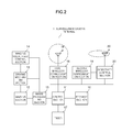
- FIG. 2 is a view illustrating a relevant portion of a surveillance camera terminal.
- the surveillance camera terminal 1 includes a control section 11, an imaging section 12, a driving mechanism section 13, an imaging visual field control section 14, an image processing section 15, a storage section 16, a timer 17, a first wireless communication section 18, a second wireless communication section 19, and a directivity control section 20.
- the control section 11 controls the operations of different sections of a main body.
- the imaging section 12 outputs about 30 frames of frame images per second which are taken by imaging an area in an imaging visual field (i.e., imaging area).
- the imaging section 12 is mounted on a camera platform (not shown) which is rotatable in the pan direction and in the tilt direction separately. The pan direction and the tilt direction are perpendicular to each other.
- the imaging section 12 has an optical system driving portion (not shown) for driving an imaging optical system and is capable of changing an imaging magnification Zoom.
- the driving mechanism section 13 has a driving source, such as a motor, for rotating the camera platform mounted with the imaging section 12 thereon in the pan direction and in the tilt direction.
- the driving mechanism section 13 also has a sensor for detecting an angle of rotation ⁇ of the camera platform in the pan direction and an angle of rotation ⁇ of the camera platform in the tilt direction.
- the imaging visual field control section 14 instructs the imaging section 12 on the imaging magnification Zoom. According to this instruction, the imaging section 12 changes the imaging magnification Zoom.
- the imaging visual field control section 14 also instructs the driving mechanism section 13 on the angle of rotation ⁇ of the camera platform in the pan direction and the angle of rotation ⁇ of the camera platform in the tilt direction. According to this instruction, the driving mechanism section 13 changes the angle of rotation ⁇ of the camera platform mounted with the imaging section 12 in the pan direction and the angle of rotation ⁇ of the camera platform in the tilt direction.
- the imaging visual field of the imaging section 12 changes with changes in the angle of rotation ⁇ of the camera platform in the pan direction, the angle of rotation ⁇ of the camera platform in the tilt direction and the imaging magnification Zoom.
- a surveillance area is predetermined for the surveillance camera terminal 1 as shown in FIG. 3 .
- the surveillance area is a region which can be imaged by the imaging section 12 changing its imaging visual field.
- the image processing section 15 processes the frame images taken by the imaging section 12 to extract a person being imaged and gives an ID to the person thus extracted.
- the "ID" is a unique value which can identify a person.
- the image processing section 15 receives outputs of the sensor which detects the angle of rotation ⁇ of the camera platform mounted with the imaging section 12 thereon in the pan direction and the angle of rotation ⁇ of the camera platform in the tilt direction. That is, the image processing section 15 acquires from the outputs of the sensor the angle of rotation ⁇ of the camera platform mounted with the imaging section 12 thereon in the pan direction and the angle of rotation ⁇ of the camera platform in the tilt direction.
- the image processing section 15 also acquires the imaging magnification Zoom of the imaging section 12 from a signal indicative of the imaging magnification Zoom inputted from the imaging section 12.
- the image processing section 15 can acquire the imaging visual field of the imaging section 12, that is, the position of the imaging area in the surveillance area from the angle of rotation ⁇ of the camera platform in the pan direction, the angle of rotation ⁇ of the camera platform in the tilt direction and the imaging magnification Zoom. Therefore, the image processing section 15 can convert the position of a person in each frame image taken by the imaging section 12 to a position in the surveillance area.
- the image processing section 15 instructs the imaging visual field control section 14 on the imaging visual field of the imaging section 12 in accordance with travel of a person being tracked.
- the image processing section 15 is configured to extract a person being imaged and track this person by utilizing a spatio-temporal MRF (Markov Random Field) model for example.
- the spatio-temporal MRF model is a spatio-temporal model expanded from an MRF model with attention focused on the correlation between spatio-temporal images in the temporal axis direction.
- the spatio-temporal MRF model is a model which defines the correlation in the temporal axis direction by dividing the area of each frame image to be subjected to processing into blocks each having several pixels X several pixels (e.g., 8 pixels X 8 pixels) and referencing a displacement vector throughout temporally successive frame images on a block-by-block basis.
- the storage section 16 stores therein an operation program for causing the main body to operate, settings data to be utilized during operation, processing data that occurs during operation, and the like.
- the timer 17 clocks current time.
- the first wireless communication section 18 is connected to a non-directional antenna 18a and controls wireless communication with another surveillance camera terminal 1.
- the second wireless communication section 19 is connected to a directional antenna 20a via the directivity control section 20.
- the directivity control section 20 changes the orientation of directivity of the directional antenna 20a.
- the second wireless communication section 19 also controls wireless communication with another surveillance camera terminal 1.
- the present wide-area surveillance system is a system configured to track a person, such as a suspicious individual having showed unusual behavior or a like person (hereinafter will be simply referred to as "suspicious individual").
- Each surveillance camera terminal 1 is assigned a surveillance area as described above. As shown in FIG. 4 , the surveillance areas of two adjacent surveillance camera terminals 1A and 1B overlap each other partially. Though FIG. 4 illustratively shows the surveillance areas of the two adjacent surveillance camera terminals 1A and 1B, the surveillance areas of another pair of adjacent surveillance camera terminals 1 also overlap each other partially.
- the overlapped area is a handover area for handing over the suspicious individual from one surveillance camera terminal 1A (or 1B) to the other surveillance camera terminal 1B (or 1A).
- the handover area is an area for the surveillance camera terminal 1B to identify the suspicious individual therein and take over the tracking of suspicious individual from the surveillance camera terminal 1A when, for example, the suspicious individual being tracked by the surveillance camera terminal 1A enters the surveillance area of the surveillance camera terminal 1B by passing through the handover area.
- the surveillance camera terminal 1 has stored in its storage section 16 the imaging visual field of the imaging section 12 (defined by the angle of rotation ⁇ in the pan direction, the angle of rotation ⁇ in the tilt direction, and the imaging magnification Zoom) which is for use in handover of the suspicious individual to the adjacent surveillance camera terminal 1 of concern.
- the imaging visual field of the imaging section 12 for use in handover of the suspicious individual is inclusive of the handover area for handing over the suspicious individual to a counterpart surveillance camera terminal 1.
- each surveillance camera terminal 1 has also stored in its storage section 16 coordinate transformation information indicative of the relative positional relationship between a two-dimensional coordinate system of each frame image taken by imaging the handover area by the imaging section 12 of the subject surveillance camera terminal 1 and a two-dimensional coordinate system of each frame image taken by imaging the handover area by the imaging section 12 of an adjacent counterpart surveillance camera terminal 1.
- the coordinate transformation information is information for projective transformation of the two-dimensional coordinate system of each frame image taken by the imaging section 12 of the subject surveillance camera terminal 1 with an imaging visual field for use in handover of the suspicious individual and the two-dimensional coordinate system of each frame image taken by the imaging section 12 of the adjacent counterpart surveillance camera terminal 1 with an imaging visual field for use in handover of the suspicious individual into a common coordinate system.
- the coordinate transformation information stored in the storage section 16 includes first and second coordinate transformation parameters to be described below.
- the first coordinate transformation parameter is a parameter for projective transformation of the two-dimensional coordinate system of each frame image taken by the imaging section 12 of the subject surveillance camera terminal 1 with the imaging visual field for use in handover of the suspicious individual into the two-dimensional coordinate system of each frame image taken by the imaging section 12 of the adjacent counterpart surveillance camera terminal 1 with the imaging visual field for use in handover of the suspicious individual.
- the second coordinate transformation parameter is a parameter for projective transformation of the two-dimensional coordinate system of each frame image taken by the imaging section 12 of the adjacent counterpart surveillance camera terminal 1 with the imaging visual field for use in handover of the suspicious individual into the two-dimensional coordinate system of each frame image taken by the imaging section 12 of the subject surveillance camera terminal 1 with the imaging visual field for use in handover of the suspicious individual.
- the coordinate transformation information may include only one of the first and second coordinate transformation parameters.
- the first and second coordinatetransformation parameters are values calculated using frame images actually taken at the time of installation of the surveillance camera terminals 1.
- the surveillance camera terminal 1 stores the first coordinate transformation parameter in its storage section 16.
- combination patterns are prepared for combining the persons positioned in the handover area imaged by the subject terminal with the persons positioned in the handover area imaged by the counterpart terminal in a one-to-one correspondence. For example, when two persons are positioned in the handover area, the number of such combination patterns prepared here is two. When three persons are positioned in the handover area, the number of such combination patterns prepared here is six.
- the subject terminal 1 For each of the persons positioned in the handover area imaged by the subject surveillance camera terminal 1, the subject terminal 1 transforms the coordinates of the position of the person of concern into the coordinate system of the counterpart terminal by using the first coordinate transformation parameter. For each of the person combination patterns, the surveillance camera terminal 1 calculates a first distance energy which is the sum total of distances between the corresponding persons in the coordinate system of the counterpart terminal. For each of the persons positioned in the handover area imaged by the counterpart terminal, the subject surveillance camera terminal 1 transforms the coordinates of the position of the person of concern into the coordinate system of the subject terminal by using the second coordinate transformation parameter. For each of the person combination patterns, the subject surveillance camera terminal 1 calculates a second distance energy which is the sum total of distances between the corresponding persons in the coordinate system of the subject terminal.
- the surveillance camera terminal 1 determines that a combination pattern such that the sum of the first distance energy and the second distance energy is the smallest of all the combinations of the persons positioned in the handover area is a proper correspondence between the persons positioned in the handover area. Therefore, when the suspicious individual is positioned in the handover area, the surveillance camera terminal 1 which takes over the tracking of the suspicious individual can acquire information on which one of the persons positioned in the handover area the suspicious individual is from the surveillance camera terminal 1 tracking the suspicious individual, thereby identifying the suspicious individual.
- the surveillance camera terminal 1 tracking the suspicious individual gives a notification of template information used for detecting the suspicious individual to the surveillance camera terminal 1 which has to take over the tracking of the suspicious individual, while the surveillance camera terminal 1 which has to take over the tracking of the suspicious individual identifies the suspicious individual by using the template information thus given.
- the surveillance camera terminal 1 which has to take over the tracking of the suspicious individual may be notified of, in addition to the template information described above, characteristics information used for detecting the suspicious individual (including, for example, information that can specify the suspicious individual by image data on the suspicious individual cut out of the image or by the shape, color, size and the like of the suspicious individual, information on the shapes or positions of face parts including eyes, nose and mouth, or like information).
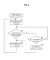
- FIG. 5 is a flowchart of an operation of the surveillance camera terminal 1.
- the surveillance camera terminal 1 starts carrying out a search process for searching the surveillance area for the suspicious individual (step S1). At that time, the surveillance camera terminal 1 does not yet track the suspicious individual (which means that the terminal 1 does not yet carry out a tracking process to be described later).
- the surveillance camera terminal 1 waits until detection of the suspicious individual by the search process started in step S1 (step S2) or until receipt of a request of handover of the suspicious individual from an adjacent surveillance camera terminal 1 (step S3).
- the imaging visual field of the imaging section 12 is changed at fixed time intervals (several seconds). Specifically, the imaging visual field control section 14 instructs the driving mechanism section 13 on an angle of rotation ⁇ of the camera platform mounted with the imaging section 12 thereon in the pan direction and an angle of rotation ⁇ of the camera platform in the tilt direction at fixed time intervals based on predetermined conditions. For example, these conditions are predetermined so that the imaging visual field of the imaging section 12 scans over the entire surveillance area.
- the imaging magnification used is a predetermined imaging magnification.
- the image processing section 15 processes a frame image taken by the imaging section 12 to extract persons imaged and gives an ID to each of the persons thus extracted. At that time, any ID is not given to a person already given an ID. For each of the persons extracted, the image processing section 15 prepares an object map which makes his or her ID correspond with his or her position in the surveillance area. The object map is given a time stamp indicative of the time at which the timer 17 clocked at the time of preparation of the object map. The image processing section 15 uses temporally successive object maps to analyze the behavior of each of the persons given respective IDs. I f there is a person showing unusual behavior (i.e., a person showing a predetermined pattern of behavior), that person is detected as a suspicious individual. Alternatively, it is possible that with the facial image of a marked person having been registered, the marked person is detected by collating the facial image of a person taken by the imaging section 12 with the facial image of the marked person and is then determined as a suspicious individual.
- step S3 the surveillance camera terminal 1 waits until the first wireless communication section 18 receives a handover request from another surveillance camera terminal 1 to the subject terminal 1. Since the first wireless communication section 18 is connected to the non-directional antenna 18a, the first wireless communication section 18 sometimes receives a handover request addressed to another terminal. When the first wireless communication section 18 receives such a handover request addressed to another terminal, the subject terminal 1 functions as a relay node. Specifically, the forwarding destination of the handover request addressed to another terminal that has been received this time is determined from all the terminals (including the terminal having received the request) except the terminal having transmitted the request and then the request is transmitted to the terminal thus determined. For example, a handover request transmitted by the surveillance camera terminal 1A shown in FIG.
- the surveillance camera terminal 1B may be transmitted by a route passing through the surveillance camera terminals 1A ⁇ 1F ⁇ 1C ⁇ 1B or a route passing through the surveillance camera terminals 1A ⁇ 1G ⁇ 1B.
- the surveillance camera terminals 1F, 1C and 1G function as relay nodes.
- the surveillance camera terminal 1 Upon detection of the suspicious individual, the surveillance camera terminal 1 starts carrying out the tracking process (step S4). When the surveillance camera terminal 1 receives a handover request addressed thereto, the terminal 1 carries out a takeover process (step S5).
- the surveillance camera terminal 1 which carries out the tracking process in step S4 will be referred to as the "handover surveillance camera terminal 1"
- the surveillance camera terminal 1 which carries out the takeover process in step S5 will be referred to as the "takeover surveillance camera terminal 1".
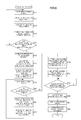
- FIG. 6 is a flowchart of the tracking process.
- the image processing section 15 of the handover surveillance camera terminal 1 captures a frame image taken by the imaging section 12 (step S11), processes the frame image, and calculates an imaging visual field (i.e., an angle of rotation ⁇ of the camera platform in the pan direction and an angle of rotation ⁇ of the camera platform in the tilt direction) with which the suspicious individual is centered in the imaging section 12 (step S12).
- the imagingmagnification Zoom of the imaging section 12 is a predetermined imaging magnification.
- the suspicious individual has been given an ID.
- the handover surveillance camera terminal 1 adjusts the imaging visual field of the imaging section 12 to that calculated in step S12 (step S13). That is, the angle of rotation ⁇ of the camera platform in the pan direction and the angle of rotation ⁇ of the camera platform in the tilt direction are adjusted to the respective angles calculated in step S12. Specifically, the image processing section 15 notifies the imaging visual field control section 14 of the angle of rotation ⁇ of the camera platform in the pan direction and the angle of rotation ⁇ of the camera platform in the tilt direction which have been calculated thereby. The imaging visual field control section 14 causes the driving mechanism section 13 to adjust the angle of rotation ⁇ of the camera platform in the pan direction and the angle of rotation ⁇ of the camera platform in the tilt direction based on the notification.
- the handover surveillance camera terminal 1 predicts another surveillance camera terminal 1 adjacent thereto which will take over the tracking of the suspicious individual (i.e., the takeover surveillance camera terminal 1) (step S14).
- the handover surveillance camera terminal 1 determines whether or not the suspicious individual being tracked is positioned near the handover area shared with the adjacent takeover surveillance camera terminal 1 predicted in step S14 (step S15). If it is not determined by the handover surveillance camera terminal 1 that the suspicious individual being tracked is positioned near the handover area shared with the takeover surveillance camera terminal 1 predicted in step S14, the handover surveillance camera terminal 1 returns the process to step S11 to repeat the operations described above.
- the handover surveillance camera terminal 1 can track the suspicious individual X while making the suspicious individual X substantially centered in the imaging visual field of the imaging section 12 as shown in fig. 7 . Even during the tracking process, the image processing section 15 prepares an object map which makes the ID of the suspicious individual correspond with the position of the suspicious individual in the surveillance area. The use of the object map allows a displacement vector defined by the direction and speed of travel of the suspicious individual to be obtained. The handover surveillance camera terminal 1 predicts the takeover surveillance camera 1 which will take over the tracking of the suspicious individual being tracked in step S14 by using the displacement vector thus obtained.
- the determination in step S15 can be simply made by determining whether or not the distance between the position of the suspicious individual and the handover area (for example, the center or boundary of the handover area) is equal to or less than a predetermined threshold value of distance from the handover area shared with the takeover surveillance camera terminal 1.
- the determination may be made in such a manner that with the speed of travel of the suspicious individual taken into consideration, whether or not the suspicious individual is positioned near the handover area is determined according to whether or not the time required for the suspicious individual being tracked to reach the handover area shared with the takeover surveillance camera terminal 1 is equal to or shorter than a predetermined time period (for example two to three seconds).
- the handover surveillance camera terminal 1 transmits a handover request to the takeover surveillance camera terminal 1 (step S16).
- the handover request in step S16 is transmitted from the first wireless communication section 18. Therefore, the handover request is not necessarily directly received by the takeover surveillance camera terminal 1. This means that the handover request may be received by the takeover surveillance camera terminal 1 through a wireless communication path via another surveillance camera terminal 1.
- the takeover surveillance camera terminal 1 having received the handover request addressed thereto carries out the takeover process in step S5.
- the directivity control section 20 adjusts the orientation of directivity of the directional antenna 20a to an orientation suited for direct communication with the takeover surveillance camera terminal 1 having received the handover request transmitted this time (step S17).
- the directivity control section 20 has stored therein the orientation of directivity of the directional antenna 20a suited for direct communication with each of the surveillance camera terminals 1 located adjacent to the handover surveillance camera terminal 1.
- the handover surveillance camera terminal 1 adjusts the imaging magnification Zoom to an imaging magnification for use in handover (step S18).
- the image processing section 15 captures and processes a frame image taken by the imaging section 12 (step S19) and determines whether or not the suspicious individual is out of the frame when the imaging visual field of the imaging section 12 is adjusted to an imaging visual field for use in handover (step S20).
- the handover surveillance camera terminal 1 calculates an imaging visual field (i.e., an angle of rotation ⁇ of the camera platform in the pan direction and an angle of rotation ⁇ of the camera platform in the tilt direction) which can position the suspicious individual therein (step 21). Though the imaging visual field which centers the suspicious individual therein may be calculated in step S21, an imaging visual field close to the imaging visual field for use in handover in which the suspicious individual is shifted from the center is preferably calculated. The handover surveillance camera terminal 1 adjusts the imaging visual field of the imaging section 12 to that calculated in step S21 (step S22) and then returns the process to step 17.
- an imaging visual field i.e., an angle of rotation ⁇ of the camera platform in the pan direction and an angle of rotation ⁇ of the camera platform in the tilt direction
- the imaging visual field for use in handover which is stored in the storage section 16 is determined as the imaging visual field of the imaging section 12 (step S23).
- the handover surveillance camera terminal 1 adjusts the imaging visual field of the imaging section 12 to the imaging visual field for use in handover (step S24).
- the takeover surveillance camera terminal 1 having received the suspicious individual handover request made by the handover surveillance camera terminal 1 in step S16 has started carrying out the takeover process shown in FIG. 8 .
- the directivity control section 20 of the takeover surveillance camera terminal 1 adjusts the orientation of directivity of the directional antenna 20a to an orientation suited for direct communication with the handover surveillance camera terminal 1 (step S31).
- the takeover surveillance camera terminal 1 also adjusts the imaging visual field of the imaging section 12 to an imaging visual field for use in handover of the suspicious individual from the handover surveillance camera terminal 1 (step S32) and then waits for a synchronous signal from the handover surveillance camera terminal 1 (step S33).
- the handover surveillance camera terminal 1 adjusts the imaging visual field of the imaging section 12 to the imaging visual field for use in handover of the suspicious individual to the takeover surveillance camera terminal 1 in step S24, the second wireless communication section 19 is ready for direct communication.
- the takeover surveillance camera terminal 1 has adjusted the imaging visual field of the imaging section 12 to the imaging visual field for use in handover of the suspicious individual from the handover surveillance camera terminal 1.
- the handover surveillance camera terminal 1 and the takeover surveillance camera terminal 1 communicate directly with each other by their respective second wireless communication sections 19.
- the handover surveillance camera terminal 1 After the handover surveillance camera terminal 1 has adjusted the imaging visual field of the imaging section 12 to the imaging visual field for use in handover of the suspicious individual to the takeover surveillance camera terminal 1 in step S24, the handover surveillance camera terminal 1 waits for the suspicious individual to enter the handover area (step S25) . Upon entry of the suspicious individual into the handover area, the handover surveillance camera terminal 1 transmits the synchronous signal to the takeover surveillance camera terminal 1 (step S26).
- the synchronous signal may be a signal for notification of a time or notification of simple reference timing.
- the synchronous signal is transmitted by the second wireless communication section 19 to the takeover surveillance camera terminal 1.
- the handover surveillance camera terminal 1 and the takeover surveillance camera terminal 1 capture frame images taken by their respective imaging sections 12 with timing based on the synchronous signal (steps S27 and S34).
- the takeover surveillance camera terminal 1 cooperates with the handover surveillance camera terminal 1 to identify the suspicious individual based on the images taken by imaging the handover area (steps S28 and S35).
- the identification of the suspicious individual can be simply made by the technique using the aforementioned first and second distance energies.
- the handover surveillance camera terminal 1 communicates directly with the takeover surveillance camera terminal 1 by the second wireless communication section 19 to notify the takeover surveillance camera terminal 1 of the result of processing of the frame images taken by the handover surveillance camera terminal 1 in step S27 (i.e., the position of each of persons positioned in the handover area (on each frame image) including the suspicious individual being tracked).
- step S5 After the takeover process in step S5 has been completed, the takeover surveillance camera terminal 1 starts carrying out the aforementioned tracking process in step S4. That is, the takeover surveillance camera terminal 1 tracks the suspicious individual taken over this time.
- the handover surveillance camera terminal 1 returns the process to step S1 after the tracking process in step S4 has been completed.
- each surveillance camera terminal 1 is capable of changing its imaging visual field.
- each surveillance camera terminal 1 may have a fixed imaging visual field.
- the area imaged in such a fixed imaging visual field is the surveillance area.
- the second wireless communication section 19 uses the directional antenna 20a to perform direct wireless communication between the handover surveillance camera terminal 1 and the takeover surveillance camera terminal 1.
- the second wireless communication section 19, directivity control section 20 and directional antenna 20a may be eliminated so long as the environment can ensure a sufficient received signal strength even in direct communication by the first wireless communication section 18 using the non-directional antenna 18a.
- the object to be tracked is a suspicious individual.
- the object to be tracked is not limited to a human, but may be any other type of mobile object such as a vehicle.
Landscapes
- Engineering & Computer Science (AREA)
- Multimedia (AREA)
- Signal Processing (AREA)
- Physics & Mathematics (AREA)
- General Physics & Mathematics (AREA)
- Computer Vision & Pattern Recognition (AREA)
- Theoretical Computer Science (AREA)
- Closed-Circuit Television Systems (AREA)
- Studio Devices (AREA)
- Alarm Systems (AREA)
Abstract
Description
- The present invention relates to a surveillance camera terminal configured to process a frame image taken by imaging a surveillance area assigned to this terminal and track a person positioned in the surveillance area. More particularly, the present invention relates to a surveillance camera terminal configured to hand over a person being tracked to another surveillance camera terminal assigned a surveillance area partially overlapping that of the subject terminal, thereby tracking the person over a wide area.
- Conventionally, a plurality of surveillance camera terminals have been used at a station, shopping center, busy streets or a like place where an unspecified number of people gather, in order to detect a person such as a suspicious individual having showed unusual behavior or a like person (hereinafter will be simply referred to as "suspicious individual") and track the suspicious individual detected. In tracking such a suspicious individual over a wide area by using the plurality of surveillance cameral terminals, the surveillance camera terminal which tracks the suspicious individual is switched to another one as the suspicious individual travels. When switching the surveillance camera terminal which tracks the suspicious individual to another one, the suspicious individual is handed over to the surveillance camera terminal which takes over the tracking. Surveillance camera terminals which can hand over the suspicious individual to each other have their respective surveillance areas partially overlapping each other. The surveillance camera terminal which takes over the tracking is caused to identify the suspicious individual among persons being imaged by using a frame image that is taken when the suspicious individual is positioned in the overlapped area (hereinafter will be referred to as "handover area").
- If the identification of the suspicious individual is unsuccessful, then the surveillance camera terminal having taken over the tracking tracks another person who is not the suspicious individual having been tracked so far. Therefore, the tracking of the suspicious individual results in a failure.
- In order to reduce the cost to be incurred for construction of a system by reducing the number of surveillance camera terminals to be used in the entire system, it has also been a practice to use surveillance camera terminals each of which is capable of changing its imaging visual field with travel of the suspicious individual, thereby increasing the surveillance area assigned to each surveillance camera terminal (see Patent Literature 1).
- Patent Literature 1: Japanese Patent Laid-Open Publication No.
2006-310901 - When the suspicious individual is handed over between surveillance camera terminals, however, wireless communication between the two surveillance camera terminals is sometimes performed not directly, but through a wireless communication path via another surveillance camera terminal. For example, when the surveillance camera terminal tracking the suspicious individual forms a wireless communication path to a surveillance camera terminal which has to take over the tracking of the suspicious individual conditionally on a received signal strength, a wireless communication path via another surveillance camera terminal is sometimes formed. As the number of surveillance camera terminals located in this wireless communication path (which are so-called relay nodes) increases, a longer delay occurs in communication between the two terminals which hand over the suspicious individual therebetween. As a result, a delay occurs in identification of the suspicious individual in the handover area, thus making it impossible to track the suspicious individual in real time and give a watchman or the like a proper instruction with respect to the suspicious individual. That is, the suspicious individual cannot be caught and is allowed to slip.
- With the surveillance camera terminals which are capable of changing their respective imaging visual fields in the surveillance areas, a delay in identification of the suspicious individual causes the two surveillance camera terminals which hand over the suspicious individual therebetween to fail to obtain any frame image that images the suspicious individual positioned in the handover area, thus resulting in a failure to track the suspicious individual.
- An object of the present invention is to provide a surveillance camera terminal which is capable of tracking an object in real time by identifying the object positioned in a handover area shared with another surveillance camera terminal which takes over the tracking of the object during the presence of the object in the handover area.
- In order to accomplish the object, a surveillance camera terminal according to the present invention is constructed as follows.
- Object extracting means is configured to extract an obj ect being imaged by processing a frame image taken by imaging means which images a surveillance area assigned to the subject terminal. Tracking means is configured to track the object extracted by object extracting means in the surveillance area. For example, frame images taken by the imaging means are processed in time sequence to track the position of the object with lapse of time. Handover means is configured to perform wireless communication with a counterpart terminal assigned a surveillance area partially overlapping the surveillance area of the subject terminal to hand over the object being tracked by the tracking means to the counterpart terminal in a handover area in which the surveillance areas of the respective terminals overlap each other. That is, when the object being tracked travels from the surveillance area of the subject terminal into that of the counterpart terminal, the handover means causes the counterpart terminal to identify the object being tracked in the handover area thereby allowing the counterpart terminal to take over the tracking of the object.
- Wireless communication path forming means is configured to form a communication path through which the wireless communication means communicates directly with the counterpart terminal to which the object is handed over when the handover means hands over the object. Such a wireless communication path can limit a delay in wireless communication between the terminals which occurs in handover of the object. Therefore, the counterpart terminal is allowed to identify the object being tracked during the presence of the object in the handover area. As a result, the object can be tracked in real time.
- It is possible that: the wireless communication means includes a first wireless communication section having a non-directional antenna and a second wireless communication section having a directional antenna; and the wireless communication path forming means causes the first wireless communication section to transmit a handover request to the counterpart terminal to which the handover means hands over the object and adjusts an orientation of directivity of the directional antenna to an orientation suited for direct communication with the counterpart terminal. In this case, the counterpart terminal which has received the handover request is simply configured to adjust the orientation of directivity of its directional antenna to an orientation suited for direction communication with the terminal which has transmitted the handover request (i.e., the terminal which is tracking the object at that time). Thus, the terminals perform wireless communication therebetween during the handover of the object by their respective second wireless communication sections.
- This feature can ensure a necessary received signal strength for wireless communication between the terminals during the handover of the object while limiting a delay in communication due to a lowered throughput.
- Prediction means may be provided which is configured to predict the counterpart terminal to which the handover means has to hand over the object being tracked based on a traveling route of the object being tracked in the surveillance area by the tracking means. In this case, the wireless communication path forming means is simply configured to form a wireless communication path for direct communication with the counterpart terminal predicted by the prediction means. This feature enables a wireless communication path to be formed for direct communication between the terminals which have to hand over the object therebetween before the object being tracked enters the handover area.
- The imaging means may have a fixed imaging visual field or a variable imaging visual field which can be changed by imaging visual field control means in accordance with a position of the object being tracked by the tracking means.
- According to the present invention, it is possible to identify the object in the handover area in which the surveillance camera terminal hands over the object to another surveillance camera terminal which takes over the tracking of the object during the presence of the object in the handover area, thereby to track the object in real time.
-
-
FIG. 1 is a schematic view illustrating the configuration of a wide-area surveillance system. -
FIG. 2 is a block diagram illustrating the configuration of a relevant portion of a surveillance camera terminal. -
FIG. 3 is a view illustrating a surveillance area assigned to the surveillance camera terminal and an imaging area. -
FIG. 4 is a view illustrating the relationship between surveillance areas of adjacent surveillance camera terminals. -
FIG. 5 is a flowchart of an operation of a surveillance camera terminal. -
FIG. 6 is a flowchart of a tracking process. -
FIG. 7 is a view illustrating images taken during the tracking process. -
FIG. 8 is a flowchart of a takeover process. - Hereinafter, a surveillance camera terminal as an embodiment of the present invention will be described.
-
FIG. 1 is a schematic view illustrating the configuration of a wide-area surveillance system using surveillance camera terminals according to an embodiment of the present invention. The wide-area surveillance system is a network system having a plurality of surveillance camera terminals 1 (1A to 1H). The wide-area surveillance system is an ad hoc network system for example. Thesurveillance camera terminals 1 are capable of data communication therebetween either directly or via anothersurveillance camera terminal 1. The data communication between thesurveillance camera terminals 1 is performed wirelessly. - The number of
surveillance camera terminals 1 forming the wide-area surveillance system is not limited to eight as illustrated inFIG. 1 , but may be any plural number. The lines interconnecting thesurveillance camera terminals 1 shown inFIG. 1 are links. In the following description, the surveillance camera terminals are denoted byreference numeral 1 particularly when thesurveillance camera terminals 1A to 1H are described without distinction therebetween. -
FIG. 2 is a view illustrating a relevant portion of a surveillance camera terminal. Thesurveillance camera terminal 1 includes acontrol section 11, animaging section 12, adriving mechanism section 13, an imaging visualfield control section 14, animage processing section 15, astorage section 16, atimer 17, a firstwireless communication section 18, a secondwireless communication section 19, and adirectivity control section 20. Thecontrol section 11 controls the operations of different sections of a main body. - The
imaging section 12 outputs about 30 frames of frame images per second which are taken by imaging an area in an imaging visual field (i.e., imaging area). Theimaging section 12 is mounted on a camera platform (not shown) which is rotatable in the pan direction and in the tilt direction separately. The pan direction and the tilt direction are perpendicular to each other. Theimaging section 12 has an optical system driving portion (not shown) for driving an imaging optical system and is capable of changing an imaging magnification Zoom. - The
driving mechanism section 13 has a driving source, such as a motor, for rotating the camera platform mounted with theimaging section 12 thereon in the pan direction and in the tilt direction. Thedriving mechanism section 13 also has a sensor for detecting an angle of rotation θ of the camera platform in the pan direction and an angle of rotation φ of the camera platform in the tilt direction. - The imaging visual
field control section 14 instructs theimaging section 12 on the imaging magnification Zoom. According to this instruction, theimaging section 12 changes the imaging magnification Zoom. The imaging visualfield control section 14 also instructs thedriving mechanism section 13 on the angle of rotation θ of the camera platform in the pan direction and the angle of rotation φ of the camera platform in the tilt direction. According to this instruction, thedriving mechanism section 13 changes the angle of rotation θ of the camera platform mounted with theimaging section 12 in the pan direction and the angle of rotation φ of the camera platform in the tilt direction. - The imaging visual field of the
imaging section 12 changes with changes in the angle of rotation θ of the camera platform in the pan direction, the angle of rotation φ of the camera platform in the tilt direction and the imaging magnification Zoom. A surveillance area is predetermined for thesurveillance camera terminal 1 as shown inFIG. 3 . The surveillance area is a region which can be imaged by theimaging section 12 changing its imaging visual field. - The
image processing section 15 processes the frame images taken by theimaging section 12 to extract a person being imaged and gives an ID to the person thus extracted. The "ID" is a unique value which can identify a person. Theimage processing section 15 receives outputs of the sensor which detects the angle of rotation θ of the camera platform mounted with theimaging section 12 thereon in the pan direction and the angle of rotation φ of the camera platform in the tilt direction. That is, theimage processing section 15 acquires from the outputs of the sensor the angle of rotation θ of the camera platform mounted with theimaging section 12 thereon in the pan direction and the angle of rotation φ of the camera platform in the tilt direction. Theimage processing section 15 also acquires the imaging magnification Zoom of theimaging section 12 from a signal indicative of the imaging magnification Zoom inputted from theimaging section 12. Theimage processing section 15 can acquire the imaging visual field of theimaging section 12, that is, the position of the imaging area in the surveillance area from the angle of rotation θ of the camera platform in the pan direction, the angle of rotation φ of the camera platform in the tilt direction and the imaging magnification Zoom. Therefore, theimage processing section 15 can convert the position of a person in each frame image taken by theimaging section 12 to a position in the surveillance area. Theimage processing section 15 instructs the imaging visualfield control section 14 on the imaging visual field of theimaging section 12 in accordance with travel of a person being tracked. - The
image processing section 15 is configured to extract a person being imaged and track this person by utilizing a spatio-temporal MRF (Markov Random Field) model for example. As is known, the spatio-temporal MRF model is a spatio-temporal model expanded from an MRF model with attention focused on the correlation between spatio-temporal images in the temporal axis direction. The spatio-temporal MRF model is a model which defines the correlation in the temporal axis direction by dividing the area of each frame image to be subjected to processing into blocks each having several pixels X several pixels (e.g., 8 pixels X 8 pixels) and referencing a displacement vector throughout temporally successive frame images on a block-by-block basis. - The
storage section 16 stores therein an operation program for causing the main body to operate, settings data to be utilized during operation, processing data that occurs during operation, and the like. Thetimer 17 clocks current time. - The first
wireless communication section 18 is connected to a non-directional antenna 18a and controls wireless communication with anothersurveillance camera terminal 1. - The second
wireless communication section 19 is connected to a directional antenna 20a via thedirectivity control section 20. Thedirectivity control section 20 changes the orientation of directivity of the directional antenna 20a. The secondwireless communication section 19 also controls wireless communication with anothersurveillance camera terminal 1. - The present wide-area surveillance system is a system configured to track a person, such as a suspicious individual having showed unusual behavior or a like person (hereinafter will be simply referred to as "suspicious individual"). Each
surveillance camera terminal 1 is assigned a surveillance area as described above. As shown inFIG. 4 , the surveillance areas of two adjacentsurveillance camera terminals FIG. 4 illustratively shows the surveillance areas of the two adjacentsurveillance camera terminals surveillance camera terminals 1 also overlap each other partially. The overlapped area is a handover area for handing over the suspicious individual from onesurveillance camera terminal 1A (or 1B) to the othersurveillance camera terminal 1B (or 1A). The handover area is an area for thesurveillance camera terminal 1B to identify the suspicious individual therein and take over the tracking of suspicious individual from thesurveillance camera terminal 1A when, for example, the suspicious individual being tracked by thesurveillance camera terminal 1A enters the surveillance area of thesurveillance camera terminal 1B by passing through the handover area. - For every adjacent
surveillance camera terminal 1, thesurveillance camera terminal 1 has stored in itsstorage section 16 the imaging visual field of the imaging section 12 (defined by the angle of rotation θ in the pan direction, the angle of rotation φ in the tilt direction, and the imaging magnification Zoom) which is for use in handover of the suspicious individual to the adjacentsurveillance camera terminal 1 of concern. The imaging visual field of theimaging section 12 for use in handover of the suspicious individual is inclusive of the handover area for handing over the suspicious individual to a counterpartsurveillance camera terminal 1. - For every adjacent
surveillance camera terminal 1, eachsurveillance camera terminal 1 has also stored in itsstorage section 16 coordinate transformation information indicative of the relative positional relationship between a two-dimensional coordinate system of each frame image taken by imaging the handover area by theimaging section 12 of the subjectsurveillance camera terminal 1 and a two-dimensional coordinate system of each frame image taken by imaging the handover area by theimaging section 12 of an adjacent counterpartsurveillance camera terminal 1. The coordinate transformation information is information for projective transformation of the two-dimensional coordinate system of each frame image taken by theimaging section 12 of the subjectsurveillance camera terminal 1 with an imaging visual field for use in handover of the suspicious individual and the two-dimensional coordinate system of each frame image taken by theimaging section 12 of the adjacent counterpartsurveillance camera terminal 1 with an imaging visual field for use in handover of the suspicious individual into a common coordinate system. In the present embodiment, the coordinate transformation information stored in thestorage section 16 includes first and second coordinate transformation parameters to be described below. The first coordinate transformation parameter is a parameter for projective transformation of the two-dimensional coordinate system of each frame image taken by theimaging section 12 of the subjectsurveillance camera terminal 1 with the imaging visual field for use in handover of the suspicious individual into the two-dimensional coordinate system of each frame image taken by theimaging section 12 of the adjacent counterpartsurveillance camera terminal 1 with the imaging visual field for use in handover of the suspicious individual. The second coordinate transformation parameter is a parameter for projective transformation of the two-dimensional coordinate system of each frame image taken by theimaging section 12 of the adjacent counterpartsurveillance camera terminal 1 with the imaging visual field for use in handover of the suspicious individual into the two-dimensional coordinate system of each frame image taken by theimaging section 12 of the subjectsurveillance camera terminal 1 with the imaging visual field for use in handover of the suspicious individual. - The coordinate transformation information may include only one of the first and second coordinate transformation parameters.
- Here, description is directed to the first and second coordinate transformation parameters. The first and second coordinatetransformation parameters are values calculated using frame images actually taken at the time of installation of the
surveillance camera terminals 1. - Initially, upon completion of installation of the
surveillance camera terminal 1, four points on the floor surface in the handover area shared with an adjacent counterpartsurveillance camera terminal 1 are marked using a tape or the like. Then, a frame image taken by theimaging section 12 of the subject terminal with the imaging visual field for use in handover of the suspicious individual is processed to detect coordinates (x, y) of the position of each of the marked four points on the frame image. Similarly, the coordinates (X, Y) of the position of each of the marked four points on a frame image taken by theimaging section 12 of theadjacent counterpart terminal 1 with the imaging visual field for use in handover of the suspicious individual are acquired from the counterpart terminal. The coordinates of the position of each of the marked points are substituted into the following equations:

to obtain simultaneous equations with eight unknowns. Eight constants: a0, b0, a1, b1, c1, a2, b2 and c2, which constitute the solution to the simultaneous equations with eight unknowns, form the first coordinate transformation parameter associated with the adjacent counterpartsurveillance camera terminal 1. Thesurveillance camera terminal 1 stores the first coordinate transformation parameter in itsstorage section 16. - Likewise, the coordinates of the position of each of the markedpoints are substituted into the following equations :


to obtain simultaneous equations with eight unknowns. Eight constants: A0, B0, A1, B1, C1, A2, B2 and C2, which constitute the solution to the simultaneous equations with eight unknowns form the second coordinate transformation parameter associated with the adjacent counterpartsurveillance camera terminal 1. Thesurveillance camera terminal 1 stores the second coordinate transformation parameter in itsstorage section 16. - In identifying a person positioned in the handover area, for each of persons imaged in the handover area of a frame image taken by the subject terminal, the coordinates of his or her position on the frame image are obtained. For each of persons imaged in the handover area of a frame image taken by the counterpart terminal, the coordinates of his or her position on the frame image are acquired from the counterpart terminal. Further, combination patterns are prepared for combining the persons positioned in the handover area imaged by the subject terminal with the persons positioned in the handover area imaged by the counterpart terminal in a one-to-one correspondence. For example, when two persons are positioned in the handover area, the number of such combination patterns prepared here is two. When three persons are positioned in the handover area, the number of such combination patterns prepared here is six.
- For each of the persons positioned in the handover area imaged by the subject
surveillance camera terminal 1, thesubject terminal 1 transforms the coordinates of the position of the person of concern into the coordinate system of the counterpart terminal by using the first coordinate transformation parameter. For each of the person combination patterns, thesurveillance camera terminal 1 calculates a first distance energy which is the sum total of distances between the corresponding persons in the coordinate system of the counterpart terminal. For each of the persons positioned in the handover area imaged by the counterpart terminal, the subjectsurveillance camera terminal 1 transforms the coordinates of the position of the person of concern into the coordinate system of the subject terminal by using the second coordinate transformation parameter. For each of the person combination patterns, the subjectsurveillance camera terminal 1 calculates a second distance energy which is the sum total of distances between the corresponding persons in the coordinate system of the subject terminal. - Subsequently, the
surveillance camera terminal 1 determines that a combination pattern such that the sum of the first distance energy and the second distance energy is the smallest of all the combinations of the persons positioned in the handover area is a proper correspondence between the persons positioned in the handover area. Therefore, when the suspicious individual is positioned in the handover area, thesurveillance camera terminal 1 which takes over the tracking of the suspicious individual can acquire information on which one of the persons positioned in the handover area the suspicious individual is from thesurveillance camera terminal 1 tracking the suspicious individual, thereby identifying the suspicious individual. - In identifying the suspicious individual positioned in the handover area, it is possible that the
surveillance camera terminal 1 tracking the suspicious individual gives a notification of template information used for detecting the suspicious individual to thesurveillance camera terminal 1 which has to take over the tracking of the suspicious individual, while thesurveillance camera terminal 1 which has to take over the tracking of the suspicious individual identifies the suspicious individual by using the template information thus given. Thesurveillance camera terminal 1 which has to take over the tracking of the suspicious individual may be notified of, in addition to the template information described above, characteristics information used for detecting the suspicious individual (including, for example, information that can specify the suspicious individual by image data on the suspicious individual cut out of the image or by the shape, color, size and the like of the suspicious individual, information on the shapes or positions of face parts including eyes, nose and mouth, or like information). - The following description is directed to the operation of the
surveillance camera terminal 1.FIG. 5 is a flowchart of an operation of thesurveillance camera terminal 1. Thesurveillance camera terminal 1 starts carrying out a search process for searching the surveillance area for the suspicious individual (step S1). At that time, thesurveillance camera terminal 1 does not yet track the suspicious individual (which means that theterminal 1 does not yet carry out a tracking process to be described later). Thesurveillance camera terminal 1 waits until detection of the suspicious individual by the search process started in step S1 (step S2) or until receipt of a request of handover of the suspicious individual from an adjacent surveillance camera terminal 1 (step S3). - In the search process started in step S1, the imaging visual field of the
imaging section 12 is changed at fixed time intervals (several seconds). Specifically, the imaging visualfield control section 14 instructs thedriving mechanism section 13 on an angle of rotation θ of the camera platform mounted with theimaging section 12 thereon in the pan direction and an angle of rotation φ of the camera platform in the tilt direction at fixed time intervals based on predetermined conditions. For example, these conditions are predetermined so that the imaging visual field of theimaging section 12 scans over the entire surveillance area. The imaging magnification used is a predetermined imaging magnification. - The
image processing section 15 processes a frame image taken by theimaging section 12 to extract persons imaged and gives an ID to each of the persons thus extracted. At that time, any ID is not given to a person already given an ID. For each of the persons extracted, theimage processing section 15 prepares an object map which makes his or her ID correspond with his or her position in the surveillance area. The object map is given a time stamp indicative of the time at which thetimer 17 clocked at the time of preparation of the object map. Theimage processing section 15 uses temporally successive object maps to analyze the behavior of each of the persons given respective IDs. I f there is a person showing unusual behavior (i.e., a person showing a predetermined pattern of behavior), that person is detected as a suspicious individual. Alternatively, it is possible that with the facial image of a marked person having been registered, the marked person is detected by collating the facial image of a person taken by theimaging section 12 with the facial image of the marked person and is then determined as a suspicious individual. - In step S3, the
surveillance camera terminal 1 waits until the firstwireless communication section 18 receives a handover request from anothersurveillance camera terminal 1 to thesubject terminal 1. Since the firstwireless communication section 18 is connected to the non-directional antenna 18a, the firstwireless communication section 18 sometimes receives a handover request addressed to another terminal. When the firstwireless communication section 18 receives such a handover request addressed to another terminal, thesubject terminal 1 functions as a relay node. Specifically, the forwarding destination of the handover request addressed to another terminal that has been received this time is determined from all the terminals (including the terminal having received the request) except the terminal having transmitted the request and then the request is transmitted to the terminal thus determined. For example, a handover request transmitted by thesurveillance camera terminal 1A shown inFIG. 1 to thesurveillance camera terminal 1B may be transmitted by a route passing through thesurveillance camera terminals 1A→1F→ 1C→1B or a route passing through thesurveillance camera terminals 1A→1G→ 1B. In such a case, thesurveillance camera terminals - Upon detection of the suspicious individual, the
surveillance camera terminal 1 starts carrying out the tracking process (step S4). When thesurveillance camera terminal 1 receives a handover request addressed thereto, the terminal 1 carries out a takeover process (step S5). - In the following description, the
surveillance camera terminal 1 which carries out the tracking process in step S4 will be referred to as the "handoversurveillance camera terminal 1", while thesurveillance camera terminal 1 which carries out the takeover process in step S5 will be referred to as the "takeoversurveillance camera terminal 1". - Description is first directed to the tracking process in step S4.
FIG. 6 is a flowchart of the tracking process. Theimage processing section 15 of the handoversurveillance camera terminal 1 captures a frame image taken by the imaging section 12 (step S11), processes the frame image, and calculates an imaging visual field (i.e., an angle of rotation θ of the camera platform in the pan direction and an angle of rotation φ of the camera platform in the tilt direction) with which the suspicious individual is centered in the imaging section 12 (step S12). At that time, the imagingmagnification Zoom of theimaging section 12 is a predetermined imaging magnification. At the time the suspicious individual is detected, the suspicious individual has been given an ID. - The handover
surveillance camera terminal 1 adjusts the imaging visual field of theimaging section 12 to that calculated in step S12 (step S13). That is, the angle of rotation θ of the camera platform in the pan direction and the angle of rotation φ of the camera platform in the tilt direction are adjusted to the respective angles calculated in step S12. Specifically, theimage processing section 15 notifies the imaging visualfield control section 14 of the angle of rotation θ of the camera platform in the pan direction and the angle of rotation φ of the camera platform in the tilt direction which have been calculated thereby. The imaging visualfield control section 14 causes thedriving mechanism section 13 to adjust the angle of rotation θ of the camera platform in the pan direction and the angle of rotation φ of the camera platform in the tilt direction based on the notification. - The handover
surveillance camera terminal 1 predicts anothersurveillance camera terminal 1 adjacent thereto which will take over the tracking of the suspicious individual (i.e., the takeover surveillance camera terminal 1) (step S14). The handoversurveillance camera terminal 1 determines whether or not the suspicious individual being tracked is positioned near the handover area shared with the adjacent takeoversurveillance camera terminal 1 predicted in step S14 (step S15). If it is not determined by the handoversurveillance camera terminal 1 that the suspicious individual being tracked is positioned near the handover area shared with the takeoversurveillance camera terminal 1 predicted in step S14, the handoversurveillance camera terminal 1 returns the process to step S11 to repeat the operations described above. - By repeating the operations of steps S11 to S15, the handover
surveillance camera terminal 1 can track the suspicious individual X while making the suspicious individual X substantially centered in the imaging visual field of theimaging section 12 as shown infig. 7 . Even during the tracking process, theimage processing section 15 prepares an object map which makes the ID of the suspicious individual correspond with the position of the suspicious individual in the surveillance area. The use of the object map allows a displacement vector defined by the direction and speed of travel of the suspicious individual to be obtained. The handoversurveillance camera terminal 1 predicts thetakeover surveillance camera 1 which will take over the tracking of the suspicious individual being tracked in step S14 by using the displacement vector thus obtained. - The determination in step S15 can be simply made by determining whether or not the distance between the position of the suspicious individual and the handover area (for example, the center or boundary of the handover area) is equal to or less than a predetermined threshold value of distance from the handover area shared with the takeover
surveillance camera terminal 1. Alternatively, the determination may be made in such a manner that with the speed of travel of the suspicious individual taken into consideration, whether or not the suspicious individual is positioned near the handover area is determined according to whether or not the time required for the suspicious individual being tracked to reach the handover area shared with the takeoversurveillance camera terminal 1 is equal to or shorter than a predetermined time period (for example two to three seconds). - If it is determined by the handover
surveillance camera terminal 1 that the suspicious individual being tracked in step S15 is positioned near the handover area shared with the takeoversurveillance camera terminal 1 predicted instep S 14, the handoversurveillance camera terminal 1 transmits a handover request to the takeover surveillance camera terminal 1 (step S16). The handover request in step S16 is transmitted from the firstwireless communication section 18. Therefore, the handover request is not necessarily directly received by the takeoversurveillance camera terminal 1. This means that the handover request may be received by the takeoversurveillance camera terminal 1 through a wireless communication path via anothersurveillance camera terminal 1. The takeoversurveillance camera terminal 1 having received the handover request addressed thereto carries out the takeover process in step S5. - After the handover
surveillance camera terminal 1 has made the request for handover of the suspicious individual in step S16, thedirectivity control section 20 adjusts the orientation of directivity of the directional antenna 20a to an orientation suited for direct communication with the takeoversurveillance camera terminal 1 having received the handover request transmitted this time (step S17). Thedirectivity control section 20 has stored therein the orientation of directivity of the directional antenna 20a suited for direct communication with each of thesurveillance camera terminals 1 located adjacent to the handoversurveillance camera terminal 1. - The handover
surveillance camera terminal 1 adjusts the imaging magnification Zoom to an imaging magnification for use in handover (step S18). Theimage processing section 15 captures and processes a frame image taken by the imaging section 12 (step S19) and determines whether or not the suspicious individual is out of the frame when the imaging visual field of theimaging section 12 is adjusted to an imaging visual field for use in handover (step S20). - If it is determined by the handover
surveillance camera terminal 1 that the suspicious individual is out of the frame in step S20, the handoversurveillance camera terminal 1 calculates an imaging visual field (i.e., an angle of rotation θ of the camera platform in the pan direction and an angle of rotation φ of the camera platform in the tilt direction) which can position the suspicious individual therein (step 21). Though the imaging visual field which centers the suspicious individual therein may be calculated in step S21, an imaging visual field close to the imaging visual field for use in handover in which the suspicious individual is shifted from the center is preferably calculated. The handoversurveillance camera terminal 1 adjusts the imaging visual field of theimaging section 12 to that calculated in step S21 (step S22) and then returns the process to step 17. - If it is not determined by the handover
surveillance camera terminal 1 that the suspicious individual is out of the frame in step S20, the imaging visual field for use in handover which is stored in thestorage section 16 is determined as the imaging visual field of the imaging section 12 (step S23). The handoversurveillance camera terminal 1 adjusts the imaging visual field of theimaging section 12 to the imaging visual field for use in handover (step S24). - The takeover
surveillance camera terminal 1 having received the suspicious individual handover request made by the handoversurveillance camera terminal 1 in step S16 has started carrying out the takeover process shown inFIG. 8 . Thedirectivity control section 20 of the takeoversurveillance camera terminal 1 adjusts the orientation of directivity of the directional antenna 20a to an orientation suited for direct communication with the handover surveillance camera terminal 1 (step S31). The takeoversurveillance camera terminal 1 also adjusts the imaging visual field of theimaging section 12 to an imaging visual field for use in handover of the suspicious individual from the handover surveillance camera terminal 1 (step S32) and then waits for a synchronous signal from the handover surveillance camera terminal 1 (step S33). - Therefore, at the time when the handover
surveillance camera terminal 1 adjusts the imaging visual field of theimaging section 12 to the imaging visual field for use in handover of the suspicious individual to the takeoversurveillance camera terminal 1 in step S24, the secondwireless communication section 19 is ready for direct communication. At that time, the takeoversurveillance camera terminal 1 has adjusted the imaging visual field of theimaging section 12 to the imaging visual field for use in handover of the suspicious individual from the handoversurveillance camera terminal 1. - From then on until completion of the handover of the tracking of the suspicious individual, the handover
surveillance camera terminal 1 and the takeoversurveillance camera terminal 1 communicate directly with each other by their respective secondwireless communication sections 19. - After the handover
surveillance camera terminal 1 has adjusted the imaging visual field of theimaging section 12 to the imaging visual field for use in handover of the suspicious individual to the takeoversurveillance camera terminal 1 in step S24, the handoversurveillance camera terminal 1 waits for the suspicious individual to enter the handover area (step S25) . Upon entry of the suspicious individual into the handover area, the handoversurveillance camera terminal 1 transmits the synchronous signal to the takeover surveillance camera terminal 1 (step S26). The synchronous signal may be a signal for notification of a time or notification of simple reference timing. The synchronous signal is transmitted by the secondwireless communication section 19 to the takeoversurveillance camera terminal 1. - The handover
surveillance camera terminal 1 and the takeoversurveillance camera terminal 1 capture frame images taken by theirrespective imaging sections 12 with timing based on the synchronous signal (steps S27 and S34). The takeoversurveillance camera terminal 1 cooperates with the handoversurveillance camera terminal 1 to identify the suspicious individual based on the images taken by imaging the handover area (steps S28 and S35). The identification of the suspicious individual can be simply made by the technique using the aforementioned first and second distance energies. At that time, the handoversurveillance camera terminal 1 communicates directly with the takeoversurveillance camera terminal 1 by the secondwireless communication section 19 to notify the takeoversurveillance camera terminal 1 of the result of processing of the frame images taken by the handoversurveillance camera terminal 1 in step S27 (i.e., the position of each of persons positioned in the handover area (on each frame image) including the suspicious individual being tracked). - Thus, it is possible to limit a delay in communication between the handover
surveillance camera terminal 1 and the takeoversurveillance camera terminal 1, thereby to identify the suspicious individual by cooperation between the handoversurveillance camera terminal 1 and the takeoversurveillance camera terminal 1 during the presence of the suspicious individual in the handover area. This makes it possible to track the suspicious individual in real time. Further, it is possible to give a watchman or the like a proper instruction with respect to the suspicious individual, thereby to catch the suspicious individual without allowing the suspicious individual to slip. - After the takeover process in step S5 has been completed, the takeover
surveillance camera terminal 1 starts carrying out the aforementioned tracking process in step S4. That is, the takeoversurveillance camera terminal 1 tracks the suspicious individual taken over this time. The handoversurveillance camera terminal 1, on the other hand, returns the process to step S1 after the tracking process in step S4 has been completed. - In the embodiment described above, each
surveillance camera terminal 1 is capable of changing its imaging visual field. However, eachsurveillance camera terminal 1 may have a fixed imaging visual field. In this case, the area imaged in such a fixed imaging visual field is the surveillance area. - In the embodiment described above, the second
wireless communication section 19 uses the directional antenna 20a to perform direct wireless communication between the handoversurveillance camera terminal 1 and the takeoversurveillance camera terminal 1. However, the secondwireless communication section 19,directivity control section 20 and directional antenna 20a may be eliminated so long as the environment can ensure a sufficient received signal strength even in direct communication by the firstwireless communication section 18 using the non-directional antenna 18a. - In the embodiment described above, the object to be tracked is a suspicious individual. The object to be tracked is not limited to a human, but may be any other type of mobile object such as a vehicle.
-
- 1(1A to 1H)
- surveillance camera terminal
- 11
- control section
- 12
- imaging section
- 13
- driving mechanism section
- 14
- imaging visual field control section
- 15
- image processing section
- 16
- storage section
- 17
- timer
- 18
- first wireless communication section
- 18a
- non-directional antenna
- 19
- second wireless communication section
- 20
- directivity control section
- 20a
- directional antenna
Claims (5)
- A surveillance camera terminal comprising:wireless communication means configured to perform wireless communication with another terminal located near the subject terminal either directly or via yet another terminal;imaging means configured to image a surveillance area assigned to the subject terminal;object extracting means configured to extract an object being imaged by processing a frame image taken by the imaging means;tracking means configured to track the object extracted by the object extracting means in the surveillance area;handover means configured to perform wireless communication with a counterpart terminal assigned a surveillance area partially overlapping the surveillance area of the subject terminal by the wireless communication means to hand over the object being tracked by the tracking means to the counterpart terminal in a handover area in which the surveillance areas of the respective terminals overlap each other; andwireless communication path forming means configured to form a wireless communication path through which the wireless communication means communicates directly with the counterpart terminal to which the object is handed over when the handover means hands over the object.
- The surveillance camera terminal according to claim 1,
wherein the wireless communication means includes a first wireless communication section having a non-directional antenna and a second wireless communication section having a directional antenna;
wherein the wireless communication path forming means causes the first wireless communication section to transmit a handover request to the counterpart terminal to which the handover means hands over the object and adjusts an orientation of directivity of the directional antenna to an orientation suited for direct communication with the counterpart terminal; and
wherein the handover means communicates directly with the counterpart terminal by the second wireless communication section. - The surveillance camera terminal according to claim 1 or 2, wherein the handover means causes the counterpart terminal to identify the object being tracked by the tracking means with use of frame images of the handover area taken by the subject terminal and the counterpart terminal.
- The surveillance camera terminal according to any one of claims 1 to 3, which is provided with prediction means configured to predict the counterpart terminal to which the handover means has to hand over the object based on a traveling route of the object being tracked in the surveillance area by the tracking means,
wherein the wireless communicationpath formingmeans forms a wireless communication path for direct communication with the counterpart terminal predicted by the prediction means. - The surveillance camera terminal according to any one of claims 1 to 4, which is provided with imaging visual field control means configured to change an imaging visual field of the imaging means in accordance with a position of the object being tracked in the surveillance area by the tracking means.
Applications Claiming Priority (2)
| Application Number | Priority Date | Filing Date | Title |
|---|---|---|---|
| JP2010057122 | 2010-03-15 | ||
| PCT/JP2011/051048 WO2011114770A1 (en) | 2010-03-15 | 2011-01-21 | Surveillance camera terminal |
Publications (2)
| Publication Number | Publication Date |
|---|---|
| EP2549752A1 true EP2549752A1 (en) | 2013-01-23 |
| EP2549752A4 EP2549752A4 (en) | 2014-12-03 |
Family
ID=44648879
Family Applications (1)
| Application Number | Title | Priority Date | Filing Date |
|---|---|---|---|
| EP11755960.9A Withdrawn EP2549752A4 (en) | 2010-03-15 | 2011-01-21 | Surveillance camera terminal |
Country Status (5)
| Country | Link |
|---|---|
| US (1) | US20130002868A1 (en) |
| EP (1) | EP2549752A4 (en) |
| JP (1) | JPWO2011114770A1 (en) |
| CN (1) | CN102754435A (en) |
| WO (1) | WO2011114770A1 (en) |
Cited By (4)
| Publication number | Priority date | Publication date | Assignee | Title |
|---|---|---|---|---|
| CN103702030A (en) * | 2013-12-25 | 2014-04-02 | 浙江宇视科技有限公司 | Scene monitoring method and moving target tracking method based on GIS (Geographic Information System) map |
| WO2016105093A1 (en) | 2014-12-26 | 2016-06-30 | Samsung Electronics Co., Ltd. | Method and apparatus for operating a security system |
| WO2018067058A1 (en) * | 2016-10-06 | 2018-04-12 | Modcam Ab | Method for sharing information in system of imaging sensors |
| EP3379826A4 (en) * | 2015-11-19 | 2019-10-23 | Hangzhou Hikvision Digital Technology Co., Ltd. | Method for monitoring moving target, and monitoring device, apparatus and system |
Families Citing this family (21)
| Publication number | Priority date | Publication date | Assignee | Title |
|---|---|---|---|---|
| JP5861420B2 (en) * | 2011-12-05 | 2016-02-16 | 株式会社ニコン | Electronic camera |
| CN102724773B (en) * | 2012-05-25 | 2015-09-02 | 西安电子科技大学 | Based on the wireless intelligent monitoring device and method of M2M communication |
| JP5743221B2 (en) * | 2012-06-29 | 2015-07-01 | カシオ計算機株式会社 | Wireless synchronization system, wireless device, sensor device, wireless synchronization method, and program |
| JP6022886B2 (en) * | 2012-10-16 | 2016-11-09 | 株式会社日立国際電気 | Wireless surveillance camera system and wireless surveillance camera device |
| CN103900554A (en) * | 2012-12-26 | 2014-07-02 | 联想(北京)有限公司 | Information processing method and guiding devices |
| CN105100577B (en) * | 2014-04-21 | 2019-03-26 | 浙江大华技术股份有限公司 | A kind of image processing method and device |
| WO2015178540A1 (en) * | 2014-05-20 | 2015-11-26 | 삼성에스디에스 주식회사 | Apparatus and method for tracking target using handover between cameras |
| WO2015198767A1 (en) * | 2014-06-27 | 2015-12-30 | 日本電気株式会社 | Abnormality detection device and abnormality detection method |
| US10664705B2 (en) | 2014-09-26 | 2020-05-26 | Nec Corporation | Object tracking apparatus, object tracking system, object tracking method, display control device, object detection device, and computer-readable medium |
| WO2016132769A1 (en) * | 2015-02-19 | 2016-08-25 | シャープ株式会社 | Imaging device, control method for imaging device, and control program |
| JP6631619B2 (en) | 2015-03-27 | 2020-01-15 | 日本電気株式会社 | Video monitoring system and video monitoring method |
| EP3089263B1 (en) * | 2015-04-29 | 2022-04-13 | Rohde & Schwarz GmbH & Co. KG | Portable directional antenna, measuring assembly and measuring method |
| JP6462528B2 (en) * | 2015-08-24 | 2019-01-30 | 三菱電機株式会社 | MOBILE BODY TRACKING DEVICE, MOBILE BODY TRACKING METHOD, AND MOBILE BODY TRACKING PROGRAM |
| WO2017037754A1 (en) * | 2015-08-28 | 2017-03-09 | Nec Corporation | Analysis apparatus, analysis method, and storage medium |
| KR20170050028A (en) * | 2015-10-29 | 2017-05-11 | 삼성에스디에스 주식회사 | System and method for searching location of object |
| CN106331653B (en) * | 2016-09-29 | 2020-01-14 | 浙江宇视科技有限公司 | Method and device for positioning sub-picture display area of panoramic camera |
| KR102575271B1 (en) * | 2016-10-17 | 2023-09-06 | 한화비전 주식회사 | Camera linked with POS apparatus and surveillance method using the same |
| JP6485490B2 (en) * | 2017-05-31 | 2019-03-20 | 株式会社ニコン | camera |
| JP6992536B2 (en) * | 2018-01-19 | 2022-01-13 | 富士通株式会社 | Observation system and observation method |
| US12505699B2 (en) * | 2020-09-11 | 2025-12-23 | Sensormatic Electronics, LLC | Method and system to provide real time interior analytics using machine learning and computer vision |
| JP2024052107A (en) * | 2022-09-30 | 2024-04-11 | ヤマハ発動機株式会社 | Driving control system, driving control method, and computer program |
Family Cites Families (10)
| Publication number | Priority date | Publication date | Assignee | Title |
|---|---|---|---|---|
| US6690374B2 (en) * | 1999-05-12 | 2004-02-10 | Imove, Inc. | Security camera system for tracking moving objects in both forward and reverse directions |
| JP2001136565A (en) * | 1999-11-09 | 2001-05-18 | Mitsubishi Electric Corp | Mobile communication device |
| JP3814779B2 (en) * | 2001-03-27 | 2006-08-30 | 三菱電機株式会社 | Intruder automatic tracking method and apparatus, and image processing apparatus |
| US20050036036A1 (en) * | 2001-07-25 | 2005-02-17 | Stevenson Neil James | Camera control apparatus and method |
| JP2005244279A (en) * | 2004-02-24 | 2005-09-08 | Matsushita Electric Ind Co Ltd | Monitoring system, monitoring apparatus and monitoring method |
| JP4478510B2 (en) * | 2004-06-03 | 2010-06-09 | キヤノン株式会社 | Camera system, camera, and camera control method |
| JP4587166B2 (en) * | 2004-09-14 | 2010-11-24 | キヤノン株式会社 | Moving body tracking system, photographing apparatus, and photographing method |
| JP4475164B2 (en) | 2005-04-26 | 2010-06-09 | 日本ビクター株式会社 | Monitoring system and monitoring method |
| US7546624B2 (en) * | 2006-01-18 | 2009-06-09 | Vishloff T Lee | Systems and methods for wireless digital video monitoring |
| US8432449B2 (en) * | 2007-08-13 | 2013-04-30 | Fuji Xerox Co., Ltd. | Hidden markov model for camera handoff |
-
2011
- 2011-01-21 JP JP2012505545A patent/JPWO2011114770A1/en active Pending
- 2011-01-21 EP EP11755960.9A patent/EP2549752A4/en not_active Withdrawn
- 2011-01-21 US US13/634,711 patent/US20130002868A1/en not_active Abandoned
- 2011-01-21 WO PCT/JP2011/051048 patent/WO2011114770A1/en not_active Ceased
- 2011-01-21 CN CN201180009393.7A patent/CN102754435A/en active Pending
Cited By (5)
| Publication number | Priority date | Publication date | Assignee | Title |
|---|---|---|---|---|
| CN103702030A (en) * | 2013-12-25 | 2014-04-02 | 浙江宇视科技有限公司 | Scene monitoring method and moving target tracking method based on GIS (Geographic Information System) map |
| WO2016105093A1 (en) | 2014-12-26 | 2016-06-30 | Samsung Electronics Co., Ltd. | Method and apparatus for operating a security system |
| EP3238442A4 (en) * | 2014-12-26 | 2018-01-03 | Samsung Electronics Co., Ltd. | Method and apparatus for operating a security system |
| EP3379826A4 (en) * | 2015-11-19 | 2019-10-23 | Hangzhou Hikvision Digital Technology Co., Ltd. | Method for monitoring moving target, and monitoring device, apparatus and system |
| WO2018067058A1 (en) * | 2016-10-06 | 2018-04-12 | Modcam Ab | Method for sharing information in system of imaging sensors |
Also Published As
| Publication number | Publication date |
|---|---|
| CN102754435A (en) | 2012-10-24 |
| JPWO2011114770A1 (en) | 2013-06-27 |
| EP2549752A4 (en) | 2014-12-03 |
| US20130002868A1 (en) | 2013-01-03 |
| WO2011114770A1 (en) | 2011-09-22 |
Similar Documents
| Publication | Publication Date | Title |
|---|---|---|
| EP2549752A1 (en) | Surveillance camera terminal | |
| EP2549753B1 (en) | Surveillance camera terminal | |
| US8115814B2 (en) | Mobile tracking system, camera and photographing method | |
| EP2458553B1 (en) | Surveillance camera terminal | |
| KR101248054B1 (en) | Object tracking system for tracing path of object and method thereof | |
| JP7459916B2 (en) | Object tracking method, object tracking device, and program | |
| KR101679318B1 (en) | Object Tracking System | |
| US9692956B2 (en) | Imaging apparatus, communication device, imaging method, and information notification method | |
| CN109491392A (en) | A kind of method and system of shared avoidance | |
| US9930119B2 (en) | Heterogeneous cellular object tracking and surveillance network | |
| KR101856548B1 (en) | Method for street view service and apparatus for using the method | |
| JP3686333B2 (en) | Moving image processing camera and image processing system using the same | |
| KR20140134505A (en) | Method for tracking image object | |
| JP2005244279A (en) | Monitoring system, monitoring apparatus and monitoring method | |
| JP4574509B2 (en) | System camera, surveillance system, and surveillance method | |
| JP5397281B2 (en) | Surveillance camera terminal | |
| JP2007208659A (en) | Linked camera system | |
| KR101856254B1 (en) | Method of sharing video stream and apparatus for using the same | |
| Castanedo et al. | Bottom-up/top-down coordination in a multiagent visual sensor network | |
| Rathinam et al. | Electronic Travelling Kit for Navigation of Visually Challenged Individuals | |
| KR101636895B1 (en) | Pupil Tracking System | |
| KR20230101161A (en) | Electronic device and method for identifying object from image | |
| WO2015170869A1 (en) | Method and system for detecting surrounding moving object using cooperative communication | |
| KR20190022283A (en) | Method for street view service and apparatus for using the method |
Legal Events
| Date | Code | Title | Description |
|---|---|---|---|
| PUAI | Public reference made under article 153(3) epc to a published international application that has entered the european phase |
Free format text: ORIGINAL CODE: 0009012 |
|
| 17P | Request for examination filed |
Effective date: 20121011 |
|
| AK | Designated contracting states |
Kind code of ref document: A1 Designated state(s): AL AT BE BG CH CY CZ DE DK EE ES FI FR GB GR HR HU IE IS IT LI LT LU LV MC MK MT NL NO PL PT RO RS SE SI SK SM TR |
|
| DAX | Request for extension of the european patent (deleted) | ||
| A4 | Supplementary search report drawn up and despatched |
Effective date: 20141104 |
|
| RIC1 | Information provided on ipc code assigned before grant |
Ipc: G08B 13/196 20060101AFI20141029BHEP Ipc: G06T 7/20 20060101ALI20141029BHEP Ipc: H04N 5/247 20060101ALI20141029BHEP Ipc: H04N 7/18 20060101ALI20141029BHEP Ipc: G06T 7/00 20060101ALI20141029BHEP |
|
| STAA | Information on the status of an ep patent application or granted ep patent |
Free format text: STATUS: THE APPLICATION IS DEEMED TO BE WITHDRAWN |
|
| 18D | Application deemed to be withdrawn |
Effective date: 20150602 |