EP2549365B1 - Touch tracking device and method for a touch screen - Google Patents
Touch tracking device and method for a touch screen Download PDFInfo
- Publication number
- EP2549365B1 EP2549365B1 EP12154439.9A EP12154439A EP2549365B1 EP 2549365 B1 EP2549365 B1 EP 2549365B1 EP 12154439 A EP12154439 A EP 12154439A EP 2549365 B1 EP2549365 B1 EP 2549365B1
- Authority
- EP
- European Patent Office
- Prior art keywords
- touch
- detected
- point
- touch point
- predicted
- Prior art date
- Legal status (The legal status is an assumption and is not a legal conclusion. Google has not performed a legal analysis and makes no representation as to the accuracy of the status listed.)
- Not-in-force
Links
Images





Classifications
-
- G—PHYSICS
- G06—COMPUTING OR CALCULATING; COUNTING
- G06F—ELECTRIC DIGITAL DATA PROCESSING
- G06F3/00—Input arrangements for transferring data to be processed into a form capable of being handled by the computer; Output arrangements for transferring data from processing unit to output unit, e.g. interface arrangements
- G06F3/01—Input arrangements or combined input and output arrangements for interaction between user and computer
- G06F3/03—Arrangements for converting the position or the displacement of a member into a coded form
- G06F3/041—Digitisers, e.g. for touch screens or touch pads, characterised by the transducing means
- G06F3/0416—Control or interface arrangements specially adapted for digitisers
-
- G—PHYSICS
- G06—COMPUTING OR CALCULATING; COUNTING
- G06F—ELECTRIC DIGITAL DATA PROCESSING
- G06F3/00—Input arrangements for transferring data to be processed into a form capable of being handled by the computer; Output arrangements for transferring data from processing unit to output unit, e.g. interface arrangements
- G06F3/01—Input arrangements or combined input and output arrangements for interaction between user and computer
- G06F3/03—Arrangements for converting the position or the displacement of a member into a coded form
- G06F3/041—Digitisers, e.g. for touch screens or touch pads, characterised by the transducing means
- G06F3/0416—Control or interface arrangements specially adapted for digitisers
- G06F3/0418—Control or interface arrangements specially adapted for digitisers for error correction or compensation, e.g. based on parallax, calibration or alignment
- G06F3/04186—Touch location disambiguation
-
- G—PHYSICS
- G06—COMPUTING OR CALCULATING; COUNTING
- G06F—ELECTRIC DIGITAL DATA PROCESSING
- G06F3/00—Input arrangements for transferring data to be processed into a form capable of being handled by the computer; Output arrangements for transferring data from processing unit to output unit, e.g. interface arrangements
- G06F3/01—Input arrangements or combined input and output arrangements for interaction between user and computer
- G06F3/03—Arrangements for converting the position or the displacement of a member into a coded form
- G06F3/041—Digitisers, e.g. for touch screens or touch pads, characterised by the transducing means
- G06F3/044—Digitisers, e.g. for touch screens or touch pads, characterised by the transducing means by capacitive means
Definitions
- the present disclosure relates to a tracking method and a touch tracking device. More particularly, the present disclosure relates to a touch tracking method and a touch tracking device for a touch screen.
- a touch screen can be classified into resistive-type, capacitive-type, optical-type, electromagnetic-type, acoustic-type and the like.
- the touch screen generates touch input signals based on positions of touch points, after which the touch input signals are then processed to present relative information on the electronic device, for instance, to display relative information on a monitor.
- the capacitive touch screen is mainly comprises of two directional electrodes, wherein the two directional electrodes are mutually perpendicular and separated by an insulating layer. Coordinates of the touch points are determined by detecting and processing the touch signals generated on the two directional electrodes.
- determining the position of the touch point is sufficient but when the touch point is dynamic, for instance, when a touch object continuously moves on a surface of the touch screen, position of the touch point changes with respect to time, thereby forming multiple touch points.
- each single touch point is determined independently in the static condition, determining a relationship between one touch point and other touch points is not possible. For instance, a touch point A is detected at a first detecting time, while a touch point B is detected at a second detecting time. Only the positions of the single touch points, A and B can be determined, but relationship between the touch point A and touch point B cannot be determined in accordance with a traditional detecting method of the static touch points mentioned above. Moreover, a touch track is also hard to draw. If a noise point exists, for example, when a noise point C exists at the second time point, the process of determining and eliminating the noise point C makes determining of the touch track more complex. In other words, it is difficult to track dynamic touch points.
- An objective of the present disclosure is to provide a touch tracking method for a touch screen.
- a touch tracking function defined by detected touch points, is used for predicting a next touch point while tracking dynamic touch points.
- the touch tracking function not only determines relationship between the detected touch points at different detecting times to draw a touch track, but also makes the touch track smooth and helps eliminate noise points effectively.
- a touch tracking method for a touch track on a touch screen comprises the steps of: a) defining a touch track function by information of detected touch points; b) calculating a predicted touch point by said touch track function; c) determining whether a next detected touch point is located within a preset scope of said predicted touch point; and d) if yes in said step (c), outputting said predicted touch point in accordance with said next detected touch point as output touch point.
- the number of said detected touch points is not less than 3, and said information of said detected touch points includes coordinates and detecting times of said detected touch points.
- a touch tracking method for a touch track on a touch screen comprises the steps of: a) detecting coordinates and detecting times of n detected touch points P1 ⁇ Pn, P1(x1, y1, t1), P2(x2, y2, t2)... Pn(xn, yn, tn), wherein n is not less than 3; b) defining a touch track function F(x, y, t) by said coordinates and detecting times (x1, y1, t1), (x2, y2, t2)...
- the touch tracking device for a touch track on the touch screen comprises of: an acquisition unit to detect information of detected touch points; and a controlling unit connected to said acquisition unit to define a touch track function by said information of said detected touch points, calculating a predicted touch point, determining whether a following detected touch point is located in a preset scope of said predicted touch point and if yes, outputting said predicted touch point as an output touch point.
- a touch object such as a finger or a stylus moves on surface of a touch screen 100 to produce successive 5 detected touch points P1, P2, P3, P4, and P5 at 5 successive detecting times.
- Each detected touch point has a coordinate (x, y) and a detecting time t. Therefore, all detected touch points have following parameters: (x1, y1, t1), (x2, y2, t2), (x3, y3, t3), (x4, y4, t4) and (x5, y5, t5).
- all detected touch points are generated by movement of the touch object, wherein the touch object has a relevant velocity and a relevant acceleration with respect to each detected touch point, wherein the relevant velocity and relevant acceleration of the touch object can be calculated based on above mentioned coordinates and detecting time of each touch point. Therefore, a touch track function F(x, y, t) can be defined based on the coordinates and the detecting time of the detected touch points.
- ( X new , Y new ) is coordinate of a new tracking point on a touch track
- ( X old , Y old ) is coordinate of an old tracking point on the touch track (i.e the coordinate of the tracking point at the last detecting time).
- a x and a y are average acceleration values across coordinate axis of several preceding tracking points (for instance, taking 5 tracking points) along X and Y coordinate axial directions respectively.
- V x and V y are average velocity values of the preceding several tracking points (for instance, taking 5 tracking points) among the new tracking points along the X and Y coordinate axial directions.
- ⁇ t is time interval between two adjacent tracking points (for instance, time interval between two detecting times).
- a x and a y can also be average acceleration values of the preceding several tracking points (for instance, taking 5 tracking points) along X and Y coordinate axial directions respectively, after cutting the maximum acceleration and the minimum acceleration.
- V x and V y can also be average velocity values of the preceding several tracking points (for instance, taking 5 tracking points) along X and Y coordinate axial directions respectively, after cutting the maximum velocity and the minimum velocity.
- acceleration and the velocity values can be calculated by the following approximate method. From a tracking point P1 to a tracking point P2 shown in FIG. 1 , a touch object can be treated as a uniform velocity motion (acceleration from P1 to P2 is zero). Velocities of P1 and P2 can be calculated by known coordinates and times of the tracking points P1 and P2. From the tracking point P2 to a tracking point P3, the touch object can be in uniform acceleration motion, and then the acceleration from P2 to P3 and the velocity of P3 can be calculated by a known coordinate and time of P3. Similarly, acceleration of P3, and velocities and accelerations of P4 and P5 can be calculated. If a touch track function F(x, y, t) is defined based on the above-mentioned 5 tracking points from P1 to P5, then these 5 tracking points are successively detected touch points occurring on the surface of the touch screen 100.
- touch track function F(x, y, t) can be defined by any other formula.
- the above-mentioned touch track function F(x, y, t) can be used to predict coordinates of predicted touch points on the touch track. That is to say, after acquiring information of the detected touch points, the touch track function is defined by the acquired information of the detected touch points. Predicted touch points can then be calculated based on the touch track function. Further to computation of the predicted touch points, it can be determined as to whether the next detected touch point is in the preset scope of a concerned predicted touch point. If yes, the predicted touch point in accordance with the next detected touch point is outputted as output touch point.
- predicted parameter (x6', y6', t6') of P6' can be calculated by a touch track function F(x, y, t).
- the preset scope 101 can be set based on the predicted touch point P6'. Coordinate (x6, y6) of a detected touch point P6 is detected to be within the preset scope 101, and therefore the touch track function F(x, y, t) is determined to be correct and maintained to be valid.
- the predicted touch point P6' is outputted as the output touch point, which means that the predicted touch point P6' is outputted to a system or an application program as a touch point is being actually touched.
- the above-mentioned preset scope 101 can be set by various methods. Two examples are taken to illustrate: first, that the preset scope 101 is a circle formed by taking the predicted touch point P6' as the center of the circle and taking half of the distance between the last detected touch point P5 and the predicted touch point P6' as the radius; second, the preset scope 101 is a circle formed by taking the predicted touch point P6' as the center of the circle and taking detecting empirical value as the radius.
- each following detected touch point is determined based on its location with respect to the preset scope of corresponding predicted touch point. If all of the several detected touch points are not located in the preset scopes of their corresponding predicted touch points, the touch track is determined to end at the predicted touch point corresponding to the first detected touch point of those several detected touch points. For example, as shown in FIG. 3 , predicted parameter (x7', y7', t7') of a predicted touch point P7' is calculated by touch track function F (x, y, t), and preset scope 102 is set based on the predicted touch point P7'. Coordinate (x7, y7) of a detected touch point P7 is detected to locate beyond the preset scope 102.
- predicted parameter (x8', y8' t8') of predicted touch point P8' continues to be calculated, and preset scope 103 is set based on the predicted touch point P8'.
- the coordinate (x8, y8) of a detected touch point P8 is detected to locate beyond the preset scope 103.
- predicted parameter (x9', y9', t9') of a predicted touch point P9' continues to be calculated, and preset scope 104 is set based on the predicted touch point P9'. Coordinate (x9, y9) of a detected touch point P9 is detected to locate beyond the preset scope 104.
- this touch track is determined to end at the predicted touch point P7' which is outputted as the ending touch point.
- a new detected touch point can be determined again as to whether it will become start point of a new touch track or the noise point.
- detected touch point P7 acts as a first touch point P1" of a new touch track needed to be confirmed, and location scope 105 is set based on the detected touch point P7.
- Coordinate (x2", y2") of a detected touch point P2" is detected to locate in the location scope 105.
- Location scope 106 is set based on the detected touch point P2".
- Coordinate (x3", y3") cof a detected touch point P3" is detected to locate in the location scope 106.
- Location scope 107 is set based on the detected touch point P3".
- Coordinate (x4",y4") of a detected touch point P4" is detected to locate in a location scope 107.
- Location scope 108 is set based on the detected touch point P4".
- Coordinate (x5", y5") of a detected touch point P5" is detected to locate in the location scope 108.
- the detected touch points from P1" to P5" are determined to constitute a new touch track, and thereby a new touch track function F(x", y", t") is defined.
- a location scope can be a circle that is formed by taking the last detected touch point as the center of the circle and taking a detected empirical value as radius.
- FIG. 6 is a tracking method on a touch screen 200 as illustrated in FIG. 7 , and mainly includes the following steps:
- the touch track function F(x, y, t) is defined by the parameters (x1, y1, t1), (x2, y2, t2)...(xn, yn, tn) of the detected points P1 ⁇ Pn.
- a predicted touch point Pn+1' is calculated by the touch track function F(x, y, t).
- step 307 it is determined as to whether the detected touch point Pn+1 is located within a preset scope 201 of the predicted touch point Pn+1'. If the detected touch point is located in the preset scope 201, the method proceeds to step 309, else the method proceeds to step 311.
- step 309 the predicted touch point Pn+1' corresponding to the detected touch point Pn+1 is outputted as an output touch point and the method returns back to step 305 after adding 1 to n.
- step 311 it is determined as to whether the detected touch points from n+2 to n+k follow the sequence of steps 305 to step 307, wherein k is not less than 3. If the detected touch point Pn+k is located in the preset scope of the predicted touch point Pn+k' calculated by the touch track function F(x, y, t), the method proceeds to step 309. If the detected touch point Pn+k is not located in the preset scope of the predicted touch point Pn+k', the method proceeds to step 313.
- step 313 the touch track is determined to end at the predicted touch point Pn+1'.
- step 315 it is determined whether a new touch track starts at the detected touch point Pn+1. If the new touch track starts at the detected touch point Pn+1, the method proceeds to step 301, else, the process proceeds to step 317.
- step 317 the detected touch point Pn+1 is eliminated as a noise point.
- the above-mentioned tracking method utilizes a touch track function defined by a known set of detected touch points to predict following touch points for tracking dynamic touch points.
- the method not only determines the relationship between detected touch points at different detecting times to draw the touch tracks, but also makes the touch track smooth and helps eliminate noise points effectively.
- FIG. 8 illustrates a method for determining whether a new touch track starts at a detected touch point Pn+1, wherein the method includes the following steps:
- step 401 the detected touch point Pn+1 is taken as a first detected touch point P1" of a new touch track to be determined, and a location scope 204 is set based on the detected touch point Pn+1.
- step 403 it is determined whether any detected touch point is detected within the location scope 204. If any detected touch point is detected within the location scope, the process proceeds to step 405, else the process proceeds to step 413.
- step 405 a detected touch point in the location scope 204 is taken as a second detected touch point P2" of the new touch track, and a location scope 205 is set based on the second detected touch point P2".
- step 407 it is determined whether any detected touch point is detected in the location scope 205. If any detected touch point is detected in the location scope 205, the process proceeds to step 409, else, the process proceeds to step 413.
- step 409 detected touch points from P2" to Pm" are determined in sequence by the method from step 405 to step 407. If the detected touch point Pm" of the new touch track exists, touch point exists in the location scope 206, and then the process proceeds to step 411, else the method proceeds to step 413, wherein m is not less than 3.
- step 411 the new touch track is confirmed, wherein the new touch track starts at the detected touch point P1". The method then proceeds to step 301.
- step 413 it is confirmed that the new touch track does not exist.
- detected touch points used for defining a touch track of the present disclosure are placed successive to each other.
- a touch tracking device is also provided. As shown in FIG. 9 , the touch tracking device 900 is used for tracking a touch track on the touch screen 200.
- the touch tracking device 900 includes an acquisition unit 920, and a controlling unit 940 connected to the acquisition unit 920.
- the acquisition unit 920 is used for detecting information of the detected touch points and further includes a storage unit 922, a detecting unit 924 and a timing unit 926.
- the information of the detected touch points includes coordinates and detecting times of the detected touch points.
- the detecting unit 924 connected to the touch screen 200, detects coordinates of the detected touch point occurring on the touch screen 200 by the user. For instance, coordinates of at least 3 detected touch points are detected.
- the timing unit 926 is used for monitoring the time.
- the timing unit 926 can also be an individual component to be integrated with the controlling unit 940, except for being included in the acquisition unit 920.
- the controlling unit 940 can be connected to the detecting unit 924 and the timing unit 926 and used for defining the touch track function based on the coordinates and the detected times of the detected touch points. Besides, the controlling unit 940 can calculate the predicted touch point according to the touch track function and determine whether the following detected touch point locates in the preset scope of this predicted touch point. Further, predicted touch point corresponding to a detected touch point can be outputted as the output touch point.
- Working structure and process of the controlling unit 940 is the same as the above-mentioned touch tracking method on the touch screen.
- the storage unit 922 can be used for storing detected empirical value.
- a preset scope can be set as a circle by taking a predicted touch point as the center of the circle and taking the detected empirical value as the radius.
- the preset scope can also be set as a circle, wherein the circle is formed by taking the predicted touch point as the center of the circle and taking half of the distance between predicted touch point and last detected touch point as the radius.
Landscapes
- Engineering & Computer Science (AREA)
- General Engineering & Computer Science (AREA)
- Theoretical Computer Science (AREA)
- Human Computer Interaction (AREA)
- Physics & Mathematics (AREA)
- General Physics & Mathematics (AREA)
- Position Input By Displaying (AREA)
- User Interface Of Digital Computer (AREA)
Description
- The present disclosure relates to a tracking method and a touch tracking device. More particularly, the present disclosure relates to a touch tracking method and a touch tracking device for a touch screen.
- The technologies for inputting data into electronic devices such as laptop and cell phone through touch screens of the devices are widely used. At present, according to the different touch point detecting principles, a touch screen can be classified into resistive-type, capacitive-type, optical-type, electromagnetic-type, acoustic-type and the like. In operation, the touch screen generates touch input signals based on positions of touch points, after which the touch input signals are then processed to present relative information on the electronic device, for instance, to display relative information on a monitor.
- To enable a touch screen, it is very important to determine position of the touch points. Taking a projected capacitive touch screen as an example, the capacitive touch screen is mainly comprises of two directional electrodes, wherein the two directional electrodes are mutually perpendicular and separated by an insulating layer. Coordinates of the touch points are determined by detecting and processing the touch signals generated on the two directional electrodes. When a touch point is static, determining the position of the touch point is sufficient but when the touch point is dynamic, for instance, when a touch object continuously moves on a surface of the touch screen, position of the touch point changes with respect to time, thereby forming multiple touch points. If the position of each single touch point is determined independently in the static condition, determining a relationship between one touch point and other touch points is not possible. For instance, a touch point A is detected at a first detecting time, while a touch point B is detected at a second detecting time. Only the positions of the single touch points, A and B can be determined, but relationship between the touch point A and touch point B cannot be determined in accordance with a traditional detecting method of the static touch points mentioned above. Moreover, a touch track is also hard to draw. If a noise point exists, for example, when a noise point C exists at the second time point, the process of determining and eliminating the noise point C makes determining of the touch track more complex. In other words, it is difficult to track dynamic touch points.
- An objective of the present disclosure is to provide a touch tracking method for a touch screen. A touch tracking function, defined by detected touch points, is used for predicting a next touch point while tracking dynamic touch points. The touch tracking function not only determines relationship between the detected touch points at different detecting times to draw a touch track, but also makes the touch track smooth and helps eliminate noise points effectively.
- A touch tracking method for a touch track on a touch screen comprises the steps of: a) defining a touch track function by information of detected touch points; b) calculating a predicted touch point by said touch track function; c) determining whether a next detected touch point is located within a preset scope of said predicted touch point; and d) if yes in said step (c), outputting said predicted touch point in accordance with said next detected touch point as output touch point.
- In one implementation, the number of said detected touch points is not less than 3, and said information of said detected touch points includes coordinates and detecting times of said detected touch points.
- A touch tracking method for a touch track on a touch screen comprises the steps of: a) detecting coordinates and detecting times of n detected touch points P1∼Pn, P1(x1, y1, t1), P2(x2, y2, t2)... Pn(xn, yn, tn), wherein n is not less than 3; b) defining a touch track function F(x, y, t) by said coordinates and detecting times (x1, y1, t1), (x2, y2, t2)... (xn, yn, tn) for n detected touch points; c) calculating a predicted touch point Pn+1' by said touch track function for n detected touch point; d) determining whether the detected touch point Pn+1 is located in a preset scope of said predicted touch point 'Pn+1'; and e) if yes in said step (d), outputting said predicted touch point Pn+1' as an output touch point.
- Another objective of the present invention is to provide a touch tracking device for a touch screen. The touch tracking device for a touch track on the touch screen comprises of: an acquisition unit to detect information of detected touch points; and a controlling unit connected to said acquisition unit to define a touch track function by said information of said detected touch points, calculating a predicted touch point, determining whether a following detected touch point is located in a preset scope of said predicted touch point and if yes, outputting said predicted touch point as an output touch point.
- The skilled artisan will understand that the drawings, described below, are for illustration purposes only. The drawings are not intended to limit the scope of the present teachings in any way. Like reference numerals designate corresponding parts throughout the several views.
-
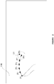
FIG. 1 is a schematic diagram of a first embodiment for determining a touch track on a touch screen of the present disclosure. -
FIG. 2 is a schematic diagram of a predicted touch point and a detected touch point on the touch track inFIG. 1 . -
FIG. 3 is a schematic diagram of the end of the touch track inFIG. 1 . -
FIG. 4 is a schematic diagram of forming a new touch track on the touch screen inFIG. 1 . -
FIG. 5 is a schematic diagram of determining noise points on the touch screen ofFIG. 1 . -
FIG. 6 is a flow chart of a touch tracking method for a touch screen. -
FIG. 7 is a schematic diagram of a touch track. -
FIG. 8 is a schematic diagram of a method for determining for a new touch track on a touch screen. -
FIG. 9 is a schematic diagram of a touch tracking device for a touch screen. - As shown in
FIG. 1 , a touch object, such as a finger or a stylus, moves on surface of atouch screen 100 to produce successive 5 detected touch points P1, P2, P3, P4, and P5 at 5 successive detecting times. Each detected touch point has a coordinate (x, y) and a detecting time t. Therefore, all detected touch points have following parameters: (x1, y1, t1), (x2, y2, t2), (x3, y3, t3), (x4, y4, t4) and (x5, y5, t5). In addition, all detected touch points are generated by movement of the touch object, wherein the touch object has a relevant velocity and a relevant acceleration with respect to each detected touch point, wherein the relevant velocity and relevant acceleration of the touch object can be calculated based on above mentioned coordinates and detecting time of each touch point. Therefore, a touch track function F(x, y, t) can be defined based on the coordinates and the detecting time of the detected touch points. - An example is taken to illustrate a touch track function F(x,y,t):


a x anda y are average acceleration values across coordinate axis of several preceding tracking points (for instance, taking 5 tracking points) along X and Y coordinate axial directions respectively.V x andV y are average velocity values of the preceding several tracking points (for instance, taking 5 tracking points) among the new tracking points along the X and Y coordinate axial directions. Δt is time interval between two adjacent tracking points (for instance, time interval between two detecting times). Moreover,a x anda y can also be average acceleration values of the preceding several tracking points (for instance, taking 5 tracking points) along X and Y coordinate axial directions respectively, after cutting the maximum acceleration and the minimum acceleration.V x andV y can also be average velocity values of the preceding several tracking points (for instance, taking 5 tracking points) along X and Y coordinate axial directions respectively, after cutting the maximum velocity and the minimum velocity. - In an embodiment, acceleration and the velocity values can be calculated by the following approximate method. From a tracking point P1 to a tracking point P2 shown in
FIG. 1 , a touch object can be treated as a uniform velocity motion (acceleration from P1 to P2 is zero). Velocities of P1 and P2 can be calculated by known coordinates and times of the tracking points P1 and P2. From the tracking point P2 to a tracking point P3, the touch object can be in uniform acceleration motion, and then the acceleration from P2 to P3 and the velocity of P3 can be calculated by a known coordinate and time of P3. Similarly, acceleration of P3, and velocities and accelerations of P4 and P5 can be calculated. If a touch track function F(x, y, t) is defined based on the above-mentioned 5 tracking points from P1 to P5, then these 5 tracking points are successively detected touch points occurring on the surface of thetouch screen 100. - In addition, the touch track function F(x, y, t) can be defined by any other formula.
- The above-mentioned touch track function F(x, y, t) can be used to predict coordinates of predicted touch points on the touch track. That is to say, after acquiring information of the detected touch points, the touch track function is defined by the acquired information of the detected touch points. Predicted touch points can then be calculated based on the touch track function. Further to computation of the predicted touch points, it can be determined as to whether the next detected touch point is in the preset scope of a concerned predicted touch point. If yes, the predicted touch point in accordance with the next detected touch point is outputted as output touch point.
- For instance, as shown in
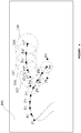
FIG. 2 , predicted parameter (x6', y6', t6') of P6', which is a predicted touch point, can be calculated by a touch track function F(x, y, t). Thepreset scope 101 can be set based on the predicted touch point P6'. Coordinate (x6, y6) of a detected touch point P6 is detected to be within thepreset scope 101, and therefore the touch track function F(x, y, t) is determined to be correct and maintained to be valid. Meanwhile, the predicted touch point P6' is outputted as the output touch point, which means that the predicted touch point P6' is outputted to a system or an application program as a touch point is being actually touched. In an embodiment, the above-mentionedpreset scope 101 can be set by various methods. Two examples are taken to illustrate: first, that thepreset scope 101 is a circle formed by taking the predicted touch point P6' as the center of the circle and taking half of the distance between the last detected touch point P5 and the predicted touch point P6' as the radius; second, thepreset scope 101 is a circle formed by taking the predicted touch point P6' as the center of the circle and taking detecting empirical value as the radius. - By the above-mentioned method, each following detected touch point is determined based on its location with respect to the preset scope of corresponding predicted touch point. If all of the several detected touch points are not located in the preset scopes of their corresponding predicted touch points, the touch track is determined to end at the predicted touch point corresponding to the first detected touch point of those several detected touch points. For example, as shown in
FIG. 3 , predicted parameter (x7', y7', t7') of a predicted touch point P7' is calculated by touch track function F (x, y, t), andpreset scope 102 is set based on the predicted touch point P7'. Coordinate (x7, y7) of a detected touch point P7 is detected to locate beyond thepreset scope 102. In the same way, predicted parameter (x8', y8' t8') of predicted touch point P8' continues to be calculated, andpreset scope 103 is set based on the predicted touch point P8'. The coordinate (x8, y8) of a detected touch point P8 is detected to locate beyond thepreset scope 103. Likewise, predicted parameter (x9', y9', t9') of a predicted touch point P9' continues to be calculated, andpreset scope 104 is set based on the predicted touch point P9'. Coordinate (x9, y9) of a detected touch point P9 is detected to locate beyond thepreset scope 104. Thus, this touch track is determined to end at the predicted touch point P7' which is outputted as the ending touch point. - After determining the end of the last touch track, a new detected touch point can be determined again as to whether it will become start point of a new touch track or the noise point. For example, as shown in
FIG. 4 , detected touch point P7 acts as a first touch point P1" of a new touch track needed to be confirmed, andlocation scope 105 is set based on the detected touch point P7. Coordinate (x2", y2") of a detected touch point P2" is detected to locate in thelocation scope 105.Location scope 106 is set based on the detected touch point P2". Coordinate (x3", y3") cof a detected touch point P3" is detected to locate in thelocation scope 106.Location scope 107 is set based on the detected touch point P3". Coordinate (x4",y4") of a detected touch point P4" is detected to locate in alocation scope 107.Location scope 108 is set based on the detected touch point P4". Coordinate (x5", y5") of a detected touch point P5" is detected to locate in thelocation scope 108. At this time, the detected touch points from P1" to P5" are determined to constitute a new touch track, and thereby a new touch track function F(x", y", t") is defined. As shown inFIG. 5 , if the detected touch point P2" is detected to locate beyond thelocation scope 105, the detected touch point P1" is confirmed and eliminated as a noise point. In an embodiment, a location scope can be a circle that is formed by taking the last detected touch point as the center of the circle and taking a detected empirical value as radius. -
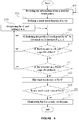
FIG. 6 is a tracking method on atouch screen 200 as illustrated inFIG. 7 , and mainly includes the following steps: - In
step 301, information of n detected touch points is detected, wherein the information can be coordinates and detecting times P1(x1,y1,t1), P2(x2, y2, t2)....Pn (xn, yn, tn), where n is not less than 3. - In
step 303, the touch track function F(x, y, t) is defined by the parameters (x1, y1, t1), (x2, y2, t2)...(xn, yn, tn) of the detected points P1∼Pn. - In
step 305, a predicted touch point Pn+1' is calculated by the touch track function F(x, y, t). - In
step 307, it is determined as to whether the detected touch point Pn+1 is located within apreset scope 201 of the predicted touch point Pn+1'. If the detected touch point is located in thepreset scope 201, the method proceeds to step 309, else the method proceeds to step 311. - In
step 309, the predicted touch point Pn+1' corresponding to the detected touch point Pn+1 is outputted as an output touch point and the method returns back to step 305 after adding 1 to n. - In
step 311, it is determined as to whether the detected touch points from n+2 to n+k follow the sequence ofsteps 305 to step 307, wherein k is not less than 3. If the detected touch point Pn+k is located in the preset scope of the predicted touch point Pn+k' calculated by the touch track function F(x, y, t), the method proceeds to step 309. If the detected touch point Pn+k is not located in the preset scope of the predicted touch point Pn+k', the method proceeds to step 313. - In
step 313, the touch track is determined to end at the predicted touch point Pn+1'. - In
step 315, it is determined whether a new touch track starts at the detected touch point Pn+1. If the new touch track starts at the detected touch point Pn+1, the method proceeds to step 301, else, the process proceeds to step 317. - In
step 317, the detected touch point Pn+1 is eliminated as a noise point. - The above-mentioned tracking method utilizes a touch track function defined by a known set of detected touch points to predict following touch points for tracking dynamic touch points. The method not only determines the relationship between detected touch points at different detecting times to draw the touch tracks, but also makes the touch track smooth and helps eliminate noise points effectively.
-
FIG. 8 , illustrates a method for determining whether a new touch track starts at a detected touch point Pn+1, wherein the method includes the following steps: - In
step 401, the detected touch point Pn+1 is taken as a first detected touch point P1" of a new touch track to be determined, and alocation scope 204 is set based on the detected touch point Pn+1. - In
step 403, it is determined whether any detected touch point is detected within thelocation scope 204. If any detected touch point is detected within the location scope, the process proceeds to step 405, else the process proceeds to step 413. - In
step 405, a detected touch point in thelocation scope 204 is taken as a second detected touch point P2" of the new touch track, and alocation scope 205 is set based on the second detected touch point P2". - In
step 407, it is determined whether any detected touch point is detected in thelocation scope 205. If any detected touch point is detected in thelocation scope 205, the process proceeds to step 409, else, the process proceeds to step 413. - In
step 409, detected touch points from P2" to Pm" are determined in sequence by the method fromstep 405 to step 407. If the detected touch point Pm" of the new touch track exists, touch point exists in thelocation scope 206, and then the process proceeds to step 411, else the method proceeds to step 413, wherein m is not less than 3. - In
step 411, the new touch track is confirmed, wherein the new touch track starts at the detected touch point P1". The method then proceeds to step 301. - In
step 413, it is confirmed that the new touch track does not exist. - In an embodiment, detected touch points used for defining a touch track of the present disclosure are placed successive to each other.
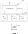
- Furthermore, a touch tracking device is also provided. As shown in
FIG. 9 , thetouch tracking device 900 is used for tracking a touch track on thetouch screen 200. Thetouch tracking device 900 includes anacquisition unit 920, and a controllingunit 940 connected to theacquisition unit 920. Theacquisition unit 920 is used for detecting information of the detected touch points and further includes astorage unit 922, a detectingunit 924 and atiming unit 926. The information of the detected touch points includes coordinates and detecting times of the detected touch points. - In an embodiment, the detecting
unit 924, connected to thetouch screen 200, detects coordinates of the detected touch point occurring on thetouch screen 200 by the user. For instance, coordinates of at least 3 detected touch points are detected. - In an embodiment, the
timing unit 926 is used for monitoring the time. Thetiming unit 926 can also be an individual component to be integrated with the controllingunit 940, except for being included in theacquisition unit 920. - In an embodiment, the controlling
unit 940 can be connected to the detectingunit 924 and thetiming unit 926 and used for defining the touch track function based on the coordinates and the detected times of the detected touch points. Besides, the controllingunit 940 can calculate the predicted touch point according to the touch track function and determine whether the following detected touch point locates in the preset scope of this predicted touch point. Further, predicted touch point corresponding to a detected touch point can be outputted as the output touch point. Working structure and process of the controllingunit 940 is the same as the above-mentioned touch tracking method on the touch screen. - In an embodiment, the
storage unit 922 can be used for storing detected empirical value. A preset scope can be set as a circle by taking a predicted touch point as the center of the circle and taking the detected empirical value as the radius. In addition, the preset scope can also be set as a circle, wherein the circle is formed by taking the predicted touch point as the center of the circle and taking half of the distance between predicted touch point and last detected touch point as the radius.
Claims (6)
- A method for tracking a plurality of touches on a touch screen (100) over time, for determining a touch track, comprising the steps of:a) detecting coordinates (x1, y1), (x2, y2) ... (xn, yn) and times t1, t2, ..., tn of n detected touch points P1(x1, y1, t1), P2(x2, y2, t2) ... Pn(xn, yn, tn) detected on a surface of said touch screen (100), wherein xi are the coordinates of the detected touch points along an X-coordinate of said touch screen (100), yi are the coordinates of the detected touch points along an Y-coordinate of said touch screen (100), ti are the times of the detected touch points on said touch screen (100), i = 1 ..., and n is an integer not less than 3;b) calculating a predicted touch point Pn+1'(xn+1, yn+1, tn+1) based on

 c) determining if a detected touch point Pn+1(xn+1, yn+1, tn+1) detected on the touch screen (100) at a time tn+1 is located within a preset scope around said predicted touch point Pn+1'(xn+1, yn+1, tn+1), wherein the preset scope is a circle formed by taking the predicted touch point Pn+1'(xn+1, yn+1, tn+1) as the center of the circle and taking half of the distance between the last detected touch point Pn(xn, yn, tn) and the predicted touch point Pn+1'(xn+1, yn+1, tn+1) as the radius of the circle; andd) outputting said predicted touch point Pn+1'(xn+1, yn+1, tn+1) as an output touch point at the time tn+1, if said detected touch point Pn+1(xn+1, yn+1, tn+1) is located within said preset scope around said predicted touch point Pn+1'(xn+1, yn+1, tn+1).
 - The touch tracking method of claim 1, wherein said step (d) further comprises returning to said step (b) after adding 1 to n.
- The touch tracking method of claim 1 or 2, further comprising, if said detected touch point Pn+1(xn+1, yn+1, tn+1) is not located within said preset scope around said predicted touch point Pn+1'(xn+1, yn+1, tn+1),e) detecting coordinates (xn+2, y n+2), (xn+3, yn+3) ... (xn+k, yn+k) and times tn+2, tn+3, ..., tn+k of n-k-1 detected touch points Pn+2(xn+2, yn+2), Pn+3(xn+3, yn+3, tn+3) ... Pn+k(xn+k, yn+k, tn+k) detected on the surface of said touch screen (100), wherein k is an integer not less than 3;f) calculating a predicted touch point Pn+2'(xn+2, yn+2, tn+2), Pn+3'(xn+3, yn+3, tn+3) ... Pn+k'(xn+k, yn+k, tn+k) using step b), wherein k is an integer not less than 3;g) determining if the detected touch points Pn+2(xn+2, yn+2), Pn+3(xn+3, yn+3, tn+3) ... Pn+k(xn+k, yn+k, tn+k) detected on the touch screen (100) at times tn+2, tn+3 ... tn+k are respectively located within a preset scope around the respective predicted touch point Pn+2'(xn+2, yn+2, tn+2), Pn+3'(xn+3, yn+3, tn+3) ... Pn+k'(xn+k, yn+k, tn+k) using step c), wherein k is an integer not less than 3; andh) ending said touch track at said predicted touch point Pn+1' if the detected touch point Pn+k is not located in the preset scope.
- The touch tracking method of claim 3, further comprising:j) determining whether the detected touch point Pn+1(xn+1, yn+1, tn+1) is a start point of a new touch track or a noise point.
- The touch tracking method of claim 4, further comprising:(i) eliminating a detected touch point Pn+1(xn+1, yn+1, tn+1) as a noise touch point if the detected touch points Pn+2(xn+2, yn+2), Pn+3(xn+3, yn+3, tn+3) ... Pn+k(xn+m, yn+m, tn+m) are not located in said preset scope, wherein m is an integer not less than 3; and(j) eliminating a detected touch point Pn+1(xn+1, yn+1, tn+1) as the start point of the new touch track if the detected touch points Pn+2(xn+2, yn+2), Pn+3(xn+3, yn+3, tn+3) ... Pn+k(xn+m, yn+m, tn+m) are located withinin said present scope, wherein m is an integer not less than 3.
- A touch tracking device for tracking a plurality of touches on a touch screen (100) over time, for determining a touch track, comprising:an acquisition unit (920) for detecting information of detected touch points on the touch screen (100), wherein the information of detected touch points consists of coordinates (x1, y1), (x2, y2) ... (xn, yn) and times t1, t2, ..., tn of n detected touch points P1(x1, y1, t1), P2(x2, y2, t2) ... Pn(xn, yn, tn) detected on a surface of said touch screen (100), wherein xi are the are the coordinates of the detected touch points along an X-coordinate of said touch screen (100), yi are the are the coordinates of the detected touch points along an Y-coordinate of said touch screen (100), ti are the are the times of the detected touch points on said touch screen (100), i = 1 ..., and n is an integer not less than 3; anda controlling unit (940) connected to said acquisition unit (920);characterized in that said controlling unit (940) is configured for performing the method steps according to any of the preceding claims.
Applications Claiming Priority (1)
| Application Number | Priority Date | Filing Date | Title |
|---|---|---|---|
| CN201110212538.5A CN102890576B (en) | 2011-07-22 | 2011-07-22 | Touch screen touch track detection method and pick-up unit |
Publications (3)
| Publication Number | Publication Date |
|---|---|
| EP2549365A2 EP2549365A2 (en) | 2013-01-23 |
| EP2549365A3 EP2549365A3 (en) | 2014-08-27 |
| EP2549365B1 true EP2549365B1 (en) | 2018-01-31 |
Family
ID=45607631
Family Applications (1)
| Application Number | Title | Priority Date | Filing Date |
|---|---|---|---|
| EP12154439.9A Not-in-force EP2549365B1 (en) | 2011-07-22 | 2012-02-08 | Touch tracking device and method for a touch screen |
Country Status (6)
| Country | Link |
|---|---|
| US (1) | US8866768B2 (en) |
| EP (1) | EP2549365B1 (en) |
| JP (1) | JP5681665B2 (en) |
| KR (1) | KR101304162B1 (en) |
| CN (1) | CN102890576B (en) |
| TW (2) | TWI450148B (en) |
Families Citing this family (31)
| Publication number | Priority date | Publication date | Assignee | Title |
|---|---|---|---|---|
| US9507454B1 (en) * | 2011-09-19 | 2016-11-29 | Parade Technologies, Ltd. | Enhanced linearity of gestures on a touch-sensitive surface |
| TWI579797B (en) * | 2012-08-31 | 2017-04-21 | 禾瑞亞科技股份有限公司 | Processor for image segmentation |
| TWI492168B (en) * | 2012-09-07 | 2015-07-11 | 友達光電股份有限公司 | Method for generating movement position coordinates |
| TWI486837B (en) * | 2012-09-18 | 2015-06-01 | Egalax Empia Technology Inc | Prediction-based touch contact tracking |
| US20150355740A1 (en) * | 2013-01-09 | 2015-12-10 | Sharp Kabushiki Kaisha | Touch panel system |
| KR102043148B1 (en) | 2013-02-19 | 2019-11-11 | 엘지전자 주식회사 | Mobile terminal and touch coordinate predicting method thereof |
| JP6177876B2 (en) * | 2013-03-15 | 2017-08-09 | シャープ株式会社 | Touch panel system |
| JP6151087B2 (en) * | 2013-05-17 | 2017-06-21 | シャープ株式会社 | Touch panel system |
| WO2014209335A1 (en) * | 2013-06-28 | 2014-12-31 | Intel Corporation | Parallel touch point detection using processor graphics |
| WO2015049934A1 (en) * | 2013-10-02 | 2015-04-09 | ソニー株式会社 | Information processing device, information processing method, and program |
| TWI556154B (en) * | 2014-06-25 | 2016-11-01 | 禾瑞亞科技股份有限公司 | Recording method, apparatus, system, and computer readable media of touch information timing |
| JP6402611B2 (en) * | 2014-12-04 | 2018-10-10 | 富士通株式会社 | Input control method, input control program, and information processing apparatus |
| US10114499B2 (en) * | 2015-08-24 | 2018-10-30 | Apple Inc. | Enhanced handling of remote controller touchpad input data |
| US9933901B2 (en) * | 2015-08-24 | 2018-04-03 | Apple Inc. | Reduction of media application response time through prediction of remote controller input data |
| JP6410693B2 (en) * | 2015-08-31 | 2018-10-24 | アルプス電気株式会社 | INPUT DEVICE, ITS CONTROL METHOD, AND PROGRAM |
| CN105353906B (en) * | 2015-10-21 | 2018-08-28 | 业成光电(深圳)有限公司 | Trajectory predictions system and trajectory predictions method |
| CN105955525B (en) * | 2016-04-21 | 2019-03-15 | 青岛海信电器股份有限公司 | Touch trajectory tracking method, device and display device |
| TWI579749B (en) * | 2016-06-14 | 2017-04-21 | 意象無限股份有限公司 | Touch control module and tracking method for touch point and touch sensitive electronic device using same |
| KR102462813B1 (en) * | 2016-07-21 | 2022-11-02 | 한화테크윈 주식회사 | The Method And The Apparatus For Setting The Parameter |
| KR102537133B1 (en) * | 2016-07-21 | 2023-05-30 | 삼성전자주식회사 | An input-latency reduction method based on a prediction of a position |
| US10353493B2 (en) * | 2016-09-30 | 2019-07-16 | Microsoft Technology Licensing, Llc | Apparatus and method of pen detection at a digitizer |
| CN106780538B (en) * | 2016-12-30 | 2018-10-12 | 南京仁光电子科技有限公司 | A kind of method of error hiding during solution image trace |
| CN108363508B (en) * | 2018-01-13 | 2021-03-23 | 江南大学 | Mark positioning non-contact visual detection method for mobile phone touch screen |
| CN110989856B (en) * | 2019-11-07 | 2024-03-22 | 北京集创北方科技股份有限公司 | Coordinate prediction method, device, equipment and storable medium |
| CN112835455A (en) * | 2019-11-22 | 2021-05-25 | 华为技术有限公司 | A method and device for predicting points drawn by a stylus |
| CN113311984A (en) * | 2020-02-27 | 2021-08-27 | 北京小米移动软件有限公司 | Touch screen track data processing method and device, mobile terminal and electronic equipment |
| US11947743B2 (en) | 2020-08-18 | 2024-04-02 | Razer (Asia-Pacific) Pte. Ltd. | Apparatus and method for controlling a pointer on a screen of an electronic device |
| KR20220049407A (en) * | 2020-10-14 | 2022-04-21 | 삼성전자주식회사 | Display apparatus and control method thereof |
| CN112306301B (en) * | 2020-11-02 | 2024-06-11 | 北京小米移动软件有限公司 | Touch data processing method, device, equipment and storage medium |
| CN113885733B (en) * | 2021-10-22 | 2024-06-18 | 深圳市泓宇星科技有限公司 | Handwriting track prediction method |
| CN114791783B (en) * | 2022-03-18 | 2024-09-17 | 联想(北京)有限公司 | Information processing method and information processing device |
Family Cites Families (21)
| Publication number | Priority date | Publication date | Assignee | Title |
|---|---|---|---|---|
| JPH06289993A (en) * | 1993-03-30 | 1994-10-18 | Matsushita Electric Ind Co Ltd | Coordinate input display device |
| JPH0962450A (en) * | 1995-08-30 | 1997-03-07 | Sanyo Electric Co Ltd | Misdetection deciding method and information processor |
| JP3052997B2 (en) * | 1996-01-12 | 2000-06-19 | 日本電気株式会社 | Handwriting input display device |
| JPH09237150A (en) * | 1996-02-29 | 1997-09-09 | Sanyo Electric Co Ltd | Prediction encoding device and decoding device |
| US7750891B2 (en) * | 2003-04-09 | 2010-07-06 | Tegic Communications, Inc. | Selective input system based on tracking of motion parameters of an input device |
| US7609278B1 (en) * | 2003-07-31 | 2009-10-27 | Adobe Systems Incorporated | Detecting backward motion represented by a path |
| CN100590579C (en) | 2007-05-16 | 2010-02-17 | 广东威创视讯科技股份有限公司 | A multi-touch positioning method |
| US20090073131A1 (en) * | 2007-09-19 | 2009-03-19 | J Touch Corporation | Method for determining multiple touch inputs on a resistive touch screen and a multiple touch controller |
| US20100073318A1 (en) * | 2008-09-24 | 2010-03-25 | Matsushita Electric Industrial Co., Ltd. | Multi-touch surface providing detection and tracking of multiple touch points |
| KR20110015461A (en) * | 2008-06-05 | 2011-02-15 | 스마트 테크놀러지스 유엘씨 | Multipoint ambiguity and occlusion resolution |
| KR100958643B1 (en) * | 2008-10-17 | 2010-05-20 | 삼성모바일디스플레이주식회사 | Touch screen display device and driving method thereof |
| US8866790B2 (en) * | 2008-10-21 | 2014-10-21 | Atmel Corporation | Multi-touch tracking |
| US9134848B2 (en) * | 2009-06-03 | 2015-09-15 | Stmicroelectronics Asia Pacific Pte Ltd | Touch tracking on a touch sensitive interface |
| US8570305B2 (en) * | 2009-07-07 | 2013-10-29 | Microsoft Corporation | Smoothing of touch input |
| JP2011028555A (en) * | 2009-07-27 | 2011-02-10 | Sony Corp | Information processor and information processing method |
| JP2011096123A (en) * | 2009-10-30 | 2011-05-12 | Sharp Corp | Input device, electronic equipment including the same, and method of inputting by the same |
| KR101628081B1 (en) * | 2009-11-05 | 2016-06-22 | 삼성전자주식회사 | System and method for sensing multiple touch points based image sensor |
| JP2011100282A (en) * | 2009-11-05 | 2011-05-19 | Seiko Epson Corp | Display device and program |
| CN102096530B (en) * | 2011-01-28 | 2013-09-18 | 广东威创视讯科技股份有限公司 | Multi-touch trajectory tracking method |
| US9542092B2 (en) * | 2011-02-12 | 2017-01-10 | Microsoft Technology Licensing, Llc | Prediction-based touch contact tracking |
| US8773377B2 (en) * | 2011-03-04 | 2014-07-08 | Microsoft Corporation | Multi-pass touch contact tracking |
-
2011
- 2011-07-22 CN CN201110212538.5A patent/CN102890576B/en not_active Expired - Fee Related
- 2011-11-03 TW TW100140152A patent/TWI450148B/en not_active IP Right Cessation
- 2011-11-03 TW TW100220773U patent/TWM423864U/en not_active IP Right Cessation
- 2011-12-09 KR KR1020110131996A patent/KR101304162B1/en not_active Expired - Fee Related
-
2012
- 2012-02-07 US US13/367,371 patent/US8866768B2/en not_active Expired - Fee Related
- 2012-02-08 EP EP12154439.9A patent/EP2549365B1/en not_active Not-in-force
- 2012-05-15 JP JP2012111586A patent/JP5681665B2/en not_active Expired - Fee Related
Non-Patent Citations (1)
| Title |
|---|
| None * |
Also Published As
| Publication number | Publication date |
|---|---|
| JP2013025788A (en) | 2013-02-04 |
| EP2549365A2 (en) | 2013-01-23 |
| JP5681665B2 (en) | 2015-03-11 |
| KR101304162B1 (en) | 2013-09-04 |
| TWI450148B (en) | 2014-08-21 |
| TWM423864U (en) | 2012-03-01 |
| CN102890576B (en) | 2016-03-02 |
| EP2549365A3 (en) | 2014-08-27 |
| US20130021272A1 (en) | 2013-01-24 |
| TW201305869A (en) | 2013-02-01 |
| KR20130011889A (en) | 2013-01-30 |
| CN102890576A (en) | 2013-01-23 |
| US8866768B2 (en) | 2014-10-21 |
Similar Documents
| Publication | Publication Date | Title |
|---|---|---|
| EP2549365A2 (en) | Touch tracking device and method for a touch screen | |
| CN105094411B (en) | Electronic device, drawing method thereof, and computer program product | |
| US8674958B1 (en) | Method and apparatus for accurate coordinate calculation of objects in touch applications | |
| JP5805890B2 (en) | Touch panel system | |
| CN103154872B (en) | Method for multiple touches on projection scan touch sensor panel to be carried out with disambiguation | |
| US20130194226A1 (en) | Method and device for determining a user's touch gesture | |
| JP6177876B2 (en) | Touch panel system | |
| US20120249487A1 (en) | Method of identifying a multi-touch shifting gesture and device using the same | |
| WO2012129975A1 (en) | Method of identifying rotation gesture and device using the same | |
| EP2691841A1 (en) | Method of identifying multi-touch scaling gesture and device using the same | |
| CN102736759A (en) | Touch screen and operating method thereof | |
| JP6005563B2 (en) | Touch panel device and control method | |
| CN105190491A (en) | Touch panel operation device and method for determining operation event on touch panel operation device | |
| CN202422047U (en) | Device for detecting touch track of touch screen | |
| JP2014109883A (en) | Electronic apparatus and method of controlling the same | |
| CN103699254A (en) | Method, device and system for multi-point touch positioning | |
| CN103186234A (en) | Control method and electronic equipment | |
| TW201310298A (en) | Touch system with track detecting function and method thereof | |
| JP2020060930A (en) | Input device | |
| CN104007865A (en) | Recognition method and electronic device | |
| US9354739B2 (en) | Self-capacitive touch control apparatus and control method thereof | |
| TWI419011B (en) | Method and system for tracking touch point | |
| JP7317730B2 (en) | Information processing device, information processing method and information processing program | |
| TWI421755B (en) | Touch panel and touching point detection method thereof | |
| JP5167519B2 (en) | Pointing device and control method thereof |
Legal Events
| Date | Code | Title | Description |
|---|---|---|---|
| PUAI | Public reference made under article 153(3) epc to a published international application that has entered the european phase |
Free format text: ORIGINAL CODE: 0009012 |
|
| AK | Designated contracting states |
Kind code of ref document: A2 Designated state(s): AL AT BE BG CH CY CZ DE DK EE ES FI FR GB GR HR HU IE IS IT LI LT LU LV MC MK MT NL NO PL PT RO RS SE SI SK SM TR |
|
| AX | Request for extension of the european patent |
Extension state: BA ME |
|
| PUAL | Search report despatched |
Free format text: ORIGINAL CODE: 0009013 |
|
| AK | Designated contracting states |
Kind code of ref document: A3 Designated state(s): AL AT BE BG CH CY CZ DE DK EE ES FI FR GB GR HR HU IE IS IT LI LT LU LV MC MK MT NL NO PL PT RO RS SE SI SK SM TR |
|
| AX | Request for extension of the european patent |
Extension state: BA ME |
|
| RIC1 | Information provided on ipc code assigned before grant |
Ipc: G06F 3/041 20060101AFI20140718BHEP |
|
| 17P | Request for examination filed |
Effective date: 20150213 |
|
| GRAP | Despatch of communication of intention to grant a patent |
Free format text: ORIGINAL CODE: EPIDOSNIGR1 |
|
| STAA | Information on the status of an ep patent application or granted ep patent |
Free format text: STATUS: GRANT OF PATENT IS INTENDED |
|
| INTG | Intention to grant announced |
Effective date: 20170302 |
|
| GRAS | Grant fee paid |
Free format text: ORIGINAL CODE: EPIDOSNIGR3 |
|
| GRAJ | Information related to disapproval of communication of intention to grant by the applicant or resumption of examination proceedings by the epo deleted |
Free format text: ORIGINAL CODE: EPIDOSDIGR1 |
|
| GRAL | Information related to payment of fee for publishing/printing deleted |
Free format text: ORIGINAL CODE: EPIDOSDIGR3 |
|
| STAA | Information on the status of an ep patent application or granted ep patent |
Free format text: STATUS: REQUEST FOR EXAMINATION WAS MADE |
|
| INTC | Intention to grant announced (deleted) | ||
| GRAR | Information related to intention to grant a patent recorded |
Free format text: ORIGINAL CODE: EPIDOSNIGR71 |
|
| STAA | Information on the status of an ep patent application or granted ep patent |
Free format text: STATUS: GRANT OF PATENT IS INTENDED |
|
| GRAA | (expected) grant |
Free format text: ORIGINAL CODE: 0009210 |
|
| STAA | Information on the status of an ep patent application or granted ep patent |
Free format text: STATUS: THE PATENT HAS BEEN GRANTED |
|
| AK | Designated contracting states |
Kind code of ref document: B1 Designated state(s): AL AT BE BG CH CY CZ DE DK EE ES FI FR GB GR HR HU IE IS IT LI LT LU LV MC MK MT NL NO PL PT RO RS SE SI SK SM TR |
|
| INTG | Intention to grant announced |
Effective date: 20171222 |
|
| REG | Reference to a national code |
Ref country code: GB Ref legal event code: FG4D Ref country code: CH Ref legal event code: EP |
|
| REG | Reference to a national code |
Ref country code: AT Ref legal event code: REF Ref document number: 967944 Country of ref document: AT Kind code of ref document: T Effective date: 20180215 |
|
| REG | Reference to a national code |
Ref country code: IE Ref legal event code: FG4D |
|
| REG | Reference to a national code |
Ref country code: DE Ref legal event code: R096 Ref document number: 602012042517 Country of ref document: DE |
|
| REG | Reference to a national code |
Ref country code: NL Ref legal event code: MP Effective date: 20180131 |
|
| REG | Reference to a national code |
Ref country code: LT Ref legal event code: MG4D |
|
| REG | Reference to a national code |
Ref country code: AT Ref legal event code: MK05 Ref document number: 967944 Country of ref document: AT Kind code of ref document: T Effective date: 20180131 |
|
| PG25 | Lapsed in a contracting state [announced via postgrant information from national office to epo] |
Ref country code: ES Free format text: LAPSE BECAUSE OF FAILURE TO SUBMIT A TRANSLATION OF THE DESCRIPTION OR TO PAY THE FEE WITHIN THE PRESCRIBED TIME-LIMIT Effective date: 20180131 Ref country code: LT Free format text: LAPSE BECAUSE OF FAILURE TO SUBMIT A TRANSLATION OF THE DESCRIPTION OR TO PAY THE FEE WITHIN THE PRESCRIBED TIME-LIMIT Effective date: 20180131 Ref country code: NL Free format text: LAPSE BECAUSE OF FAILURE TO SUBMIT A TRANSLATION OF THE DESCRIPTION OR TO PAY THE FEE WITHIN THE PRESCRIBED TIME-LIMIT Effective date: 20180131 Ref country code: FI Free format text: LAPSE BECAUSE OF FAILURE TO SUBMIT A TRANSLATION OF THE DESCRIPTION OR TO PAY THE FEE WITHIN THE PRESCRIBED TIME-LIMIT Effective date: 20180131 Ref country code: NO Free format text: LAPSE BECAUSE OF FAILURE TO SUBMIT A TRANSLATION OF THE DESCRIPTION OR TO PAY THE FEE WITHIN THE PRESCRIBED TIME-LIMIT Effective date: 20180430 Ref country code: HR Free format text: LAPSE BECAUSE OF FAILURE TO SUBMIT A TRANSLATION OF THE DESCRIPTION OR TO PAY THE FEE WITHIN THE PRESCRIBED TIME-LIMIT Effective date: 20180131 |
|
| PG25 | Lapsed in a contracting state [announced via postgrant information from national office to epo] |
Ref country code: LV Free format text: LAPSE BECAUSE OF FAILURE TO SUBMIT A TRANSLATION OF THE DESCRIPTION OR TO PAY THE FEE WITHIN THE PRESCRIBED TIME-LIMIT Effective date: 20180131 Ref country code: SE Free format text: LAPSE BECAUSE OF FAILURE TO SUBMIT A TRANSLATION OF THE DESCRIPTION OR TO PAY THE FEE WITHIN THE PRESCRIBED TIME-LIMIT Effective date: 20180131 Ref country code: GR Free format text: LAPSE BECAUSE OF FAILURE TO SUBMIT A TRANSLATION OF THE DESCRIPTION OR TO PAY THE FEE WITHIN THE PRESCRIBED TIME-LIMIT Effective date: 20180501 Ref country code: RS Free format text: LAPSE BECAUSE OF FAILURE TO SUBMIT A TRANSLATION OF THE DESCRIPTION OR TO PAY THE FEE WITHIN THE PRESCRIBED TIME-LIMIT Effective date: 20180131 Ref country code: AT Free format text: LAPSE BECAUSE OF FAILURE TO SUBMIT A TRANSLATION OF THE DESCRIPTION OR TO PAY THE FEE WITHIN THE PRESCRIBED TIME-LIMIT Effective date: 20180131 Ref country code: IS Free format text: LAPSE BECAUSE OF FAILURE TO SUBMIT A TRANSLATION OF THE DESCRIPTION OR TO PAY THE FEE WITHIN THE PRESCRIBED TIME-LIMIT Effective date: 20180531 Ref country code: PL Free format text: LAPSE BECAUSE OF FAILURE TO SUBMIT A TRANSLATION OF THE DESCRIPTION OR TO PAY THE FEE WITHIN THE PRESCRIBED TIME-LIMIT Effective date: 20180131 Ref country code: BG Free format text: LAPSE BECAUSE OF FAILURE TO SUBMIT A TRANSLATION OF THE DESCRIPTION OR TO PAY THE FEE WITHIN THE PRESCRIBED TIME-LIMIT Effective date: 20180430 |
|
| REG | Reference to a national code |
Ref country code: DE Ref legal event code: R119 Ref document number: 602012042517 Country of ref document: DE |
|
| REG | Reference to a national code |
Ref country code: CH Ref legal event code: PL |
|
| PG25 | Lapsed in a contracting state [announced via postgrant information from national office to epo] |
Ref country code: IT Free format text: LAPSE BECAUSE OF FAILURE TO SUBMIT A TRANSLATION OF THE DESCRIPTION OR TO PAY THE FEE WITHIN THE PRESCRIBED TIME-LIMIT Effective date: 20180131 Ref country code: RO Free format text: LAPSE BECAUSE OF FAILURE TO SUBMIT A TRANSLATION OF THE DESCRIPTION OR TO PAY THE FEE WITHIN THE PRESCRIBED TIME-LIMIT Effective date: 20180131 Ref country code: EE Free format text: LAPSE BECAUSE OF FAILURE TO SUBMIT A TRANSLATION OF THE DESCRIPTION OR TO PAY THE FEE WITHIN THE PRESCRIBED TIME-LIMIT Effective date: 20180131 Ref country code: AL Free format text: LAPSE BECAUSE OF FAILURE TO SUBMIT A TRANSLATION OF THE DESCRIPTION OR TO PAY THE FEE WITHIN THE PRESCRIBED TIME-LIMIT Effective date: 20180131 |
|
| REG | Reference to a national code |
Ref country code: IE Ref legal event code: MM4A |
|
| REG | Reference to a national code |
Ref country code: BE Ref legal event code: MM Effective date: 20180228 |
|
| PG25 | Lapsed in a contracting state [announced via postgrant information from national office to epo] |
Ref country code: SM Free format text: LAPSE BECAUSE OF FAILURE TO SUBMIT A TRANSLATION OF THE DESCRIPTION OR TO PAY THE FEE WITHIN THE PRESCRIBED TIME-LIMIT Effective date: 20180131 Ref country code: CH Free format text: LAPSE BECAUSE OF NON-PAYMENT OF DUE FEES Effective date: 20180228 Ref country code: DK Free format text: LAPSE BECAUSE OF FAILURE TO SUBMIT A TRANSLATION OF THE DESCRIPTION OR TO PAY THE FEE WITHIN THE PRESCRIBED TIME-LIMIT Effective date: 20180131 Ref country code: SK Free format text: LAPSE BECAUSE OF FAILURE TO SUBMIT A TRANSLATION OF THE DESCRIPTION OR TO PAY THE FEE WITHIN THE PRESCRIBED TIME-LIMIT Effective date: 20180131 Ref country code: LU Free format text: LAPSE BECAUSE OF NON-PAYMENT OF DUE FEES Effective date: 20180208 Ref country code: LI Free format text: LAPSE BECAUSE OF NON-PAYMENT OF DUE FEES Effective date: 20180228 Ref country code: MC Free format text: LAPSE BECAUSE OF FAILURE TO SUBMIT A TRANSLATION OF THE DESCRIPTION OR TO PAY THE FEE WITHIN THE PRESCRIBED TIME-LIMIT Effective date: 20180131 Ref country code: CZ Free format text: LAPSE BECAUSE OF FAILURE TO SUBMIT A TRANSLATION OF THE DESCRIPTION OR TO PAY THE FEE WITHIN THE PRESCRIBED TIME-LIMIT Effective date: 20180131 |
|
| PLBE | No opposition filed within time limit |
Free format text: ORIGINAL CODE: 0009261 |
|
| STAA | Information on the status of an ep patent application or granted ep patent |
Free format text: STATUS: NO OPPOSITION FILED WITHIN TIME LIMIT |
|
| GBPC | Gb: european patent ceased through non-payment of renewal fee |
Effective date: 20180430 |
|
| 26N | No opposition filed |
Effective date: 20181102 |
|
| PG25 | Lapsed in a contracting state [announced via postgrant information from national office to epo] |
Ref country code: IE Free format text: LAPSE BECAUSE OF NON-PAYMENT OF DUE FEES Effective date: 20180208 Ref country code: DE Free format text: LAPSE BECAUSE OF NON-PAYMENT OF DUE FEES Effective date: 20180901 |
|
| PG25 | Lapsed in a contracting state [announced via postgrant information from national office to epo] |
Ref country code: SI Free format text: LAPSE BECAUSE OF FAILURE TO SUBMIT A TRANSLATION OF THE DESCRIPTION OR TO PAY THE FEE WITHIN THE PRESCRIBED TIME-LIMIT Effective date: 20180131 Ref country code: BE Free format text: LAPSE BECAUSE OF NON-PAYMENT OF DUE FEES Effective date: 20180228 Ref country code: GB Free format text: LAPSE BECAUSE OF NON-PAYMENT OF DUE FEES Effective date: 20180430 |
|
| PG25 | Lapsed in a contracting state [announced via postgrant information from national office to epo] |
Ref country code: FR Free format text: LAPSE BECAUSE OF NON-PAYMENT OF DUE FEES Effective date: 20180331 |
|
| PG25 | Lapsed in a contracting state [announced via postgrant information from national office to epo] |
Ref country code: MT Free format text: LAPSE BECAUSE OF NON-PAYMENT OF DUE FEES Effective date: 20180208 |
|
| PG25 | Lapsed in a contracting state [announced via postgrant information from national office to epo] |
Ref country code: TR Free format text: LAPSE BECAUSE OF FAILURE TO SUBMIT A TRANSLATION OF THE DESCRIPTION OR TO PAY THE FEE WITHIN THE PRESCRIBED TIME-LIMIT Effective date: 20180131 |
|
| PG25 | Lapsed in a contracting state [announced via postgrant information from national office to epo] |
Ref country code: HU Free format text: LAPSE BECAUSE OF FAILURE TO SUBMIT A TRANSLATION OF THE DESCRIPTION OR TO PAY THE FEE WITHIN THE PRESCRIBED TIME-LIMIT; INVALID AB INITIO Effective date: 20120208 Ref country code: PT Free format text: LAPSE BECAUSE OF FAILURE TO SUBMIT A TRANSLATION OF THE DESCRIPTION OR TO PAY THE FEE WITHIN THE PRESCRIBED TIME-LIMIT Effective date: 20180131 |
|
| PG25 | Lapsed in a contracting state [announced via postgrant information from national office to epo] |
Ref country code: MK Free format text: LAPSE BECAUSE OF NON-PAYMENT OF DUE FEES Effective date: 20180131 Ref country code: CY Free format text: LAPSE BECAUSE OF FAILURE TO SUBMIT A TRANSLATION OF THE DESCRIPTION OR TO PAY THE FEE WITHIN THE PRESCRIBED TIME-LIMIT Effective date: 20180131 |