EP2549358A2 - Expansion card - Google Patents
Expansion card Download PDFInfo
- Publication number
- EP2549358A2 EP2549358A2 EP11194037A EP11194037A EP2549358A2 EP 2549358 A2 EP2549358 A2 EP 2549358A2 EP 11194037 A EP11194037 A EP 11194037A EP 11194037 A EP11194037 A EP 11194037A EP 2549358 A2 EP2549358 A2 EP 2549358A2
- Authority
- EP
- European Patent Office
- Prior art keywords
- sidewall
- expansion card
- main body
- fixing
- bottom plate
- Prior art date
- Legal status (The legal status is an assumption and is not a legal conclusion. Google has not performed a legal analysis and makes no representation as to the accuracy of the status listed.)
- Withdrawn
Links
Images




Classifications
-
- G—PHYSICS
- G06—COMPUTING OR CALCULATING; COUNTING
- G06F—ELECTRIC DIGITAL DATA PROCESSING
- G06F1/00—Details not covered by groups G06F3/00 - G06F13/00 and G06F21/00
- G06F1/16—Constructional details or arrangements
- G06F1/18—Packaging or power distribution
- G06F1/183—Internal mounting support structures, e.g. for supporting printed circuit boards
- G06F1/185—Mounting of expansion boards
Definitions
- the present disclosure relates to an expansion card.
- Expansion cards are inserted into expansion slots of servers for adding functionality to the servers.
- the expansion slots are positioned on a sidewall parallel to the inserting direction of the expansion card and are not easy to coupled with the expansion card. Therefore, it is very inconvenient to assemble the expansion cards to the servers or disassemble the expansion cards from the servers.
- FIG. 1 is a schematic view of an expansion card and a main board, according to an exemplary embodiment.
- FIG. 2 is a schematic view of the expansion card of FIG. 1 .
- FIG. 3 is a schematic view of the expansion card of FIG. 1 , with the cover removed.
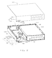
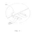
- FIG. 4 is a schematic, enlarged view of a portion IV of the expansion card of FIG. 3 .
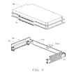
- FIG. 5 is a schematic, exploded view of a main body and an outer frame of the expansion card of FIG. 3 .
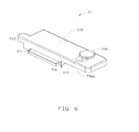
- FIG. 6 is a schematic view of a sliding block of the expansion card of FIG. 3 .
- FIG. 7 is a schematic, assembled view of a torsional spring and a buckle of the expansion card of FIG. 3 .
- FIG. 8 is a schematic view of the expansion card of FIG. 1 , in a first working state.
- FIG. 9 is a schematic view of the expansion card of FIG. 1 , in a second working state.
- an expansion card 100 is inserted into two expansion slots 222 of a server 200 for adding functionality to the server 200.
- the server 200 includes a main board 210 and a housing 220 positioned on the main board 210.
- the housing 220 receives the expansion card 100, and includes an inner sidewall 221 parallel to the inserting direction of the expansion card 100.
- the two expansion slots 222 are positioned on the inner sidewall 221.
- the expansion card 100 includes a cuboid shell 10, a main body 30, an outer frame 50, and a transmission element 70.
- the main body 30, the outer frame 50, and the transmission element 70 are received in the shell 10.
- the shell 10 includes a top cover 11 and a bottom cover 13.
- the top cover 11 includes a top plate 111 and a first sidewall 113 perpendicular to the top plate 111.
- a locking assembly 115 is positioned on the first sidewall 113.
- the locking assembly 115 includes a rectangular fixing groove 116 passing through the first sidewall 113 and a rod 117 connecting between two opposite edges of the fixing groove 116.
- the bottom cover 13 includes a bottom plate 131, a second sidewall 132, a third sidewall 133 parallel to the second sidewall 132, and a fourth sidewall 134 perpendicularly connected between the second sidewall 132 and the third sidewall 133.
- the fourth sidewall 134 is parallel to the first sidewall 131.
- the second sidewall 132 faces the inner sidewall 221 of the server 200, and defines two through slots 132a passing through the second sidewall 132 and corresponding to the two expansion slots 222.
- the bottom plate 131 positions two parallel rails 131 a adjacent to the cross of the third sidewall 133 and the first sidewall 113.
- each rail 131 a is L-shaped, and includes a connecting portion 131 b and a latching portion 131 c.
- the connecting portion 131 b is fixed on the bottom plate 131.
- the latching portion 131 c is connected perpendicularly to the connecting portion 131 b, and bends towards the other rail 131 a.
- the third sidewall 133 defines a pinhole 133a adjacent to the bottom plate 131.
- the orthogonal projection of the pinhole 133a on the bottom plate 131 is between the two rails 131 a.
- Two bars 135 are arranged in a straight line on the bottom plate 131 along the lengthwise direction of the second sidewall 132. The two bars 135 cooperate with the second sidewall 132 to limit the sliding range of the main body 30.
- the number of the bars 135 is not limited in this embodiment.
- the main body 30 is received in the receiving space between the two bars 135 and the second sidewall 132.
- Two connectors 31 are positioned on a surface of the main body 30 facing the two through slots 132a, and can extend outwards from the two through slots 132a respectively, and thus coupling with the corresponding expansion slots 222.
- the outer frame 50 covers the outer sidewall of the main body 30 excluding a surface on which the two connectors 31 are positioned, and includes two parallel fixing arms 51 and a connecting arm 53 connecting between the two fixing arms 51.
- the two fixing arms 51 are fixed on the main body 30.
- the distance between a surface of the connecting arm 53 away from the main body 30 and a surface of the connector 31 away from the main body 30 is substantially equal to the distance between each bar 135 and the second sidewall 132.
- the two fixing arms 51 contact with the top plate 111 and the bottom plate 131, and thus the two connectors 31 can slide towards the second sidewall 132 and extend outwards from the two through slots 132a.
- the surfaces of the two fixing arms 51 contacting with the top plate 111 and the bottom plate 131 are smooth to reduce the friction force between the outer frame 50 and the top plate 111, and between the outer frame 50 and the bottom plate 131.
- the transmission element 70 includes a cuboid sliding block 71, a locating element 72, a connecting pole 73, a fixing shaft 701, an I-shaped rotating shaft 718, a buckle 74, and a torsion spring 75.
- Two opposite surfaces of the sliding block 71 along the lengthwise direction are arranged respectively in a protrusion 711.
- Each protrusion 711 is received in a receiving space formed by the connecting portion 131 b and the latching portion 131 c of the corresponding rail 131 a, and thus the sliding block 71 can slide along the rails 131 a.
- a pin 713 is arranged in the sliding block 71 corresponding to the pinhole 133a.
- the sliding block 71 When the sliding block 71 slides in the rails 131 a, the pin 713 can extend through the pinhole 133a.
- the sliding block 71 further includes a top surface 715 away from the bottom plate 131 and a bottom surface 716 opposite to the top surface 715.
- the bottom surface 716 defines a cutout 716a away from the pin 713.
- One end of the sliding block 71 away from the pin 713 defines a through hole 717 passing through the top surface 715 and the bottom surface 716.
- the locating element 72 includes a locating frame 721 and a locating shaft 723.
- the locating frame 721 includes two parallel first plates 721 a and a second plate 721 b perpendicularly connected between the two first plates 721 a.
- the second plate 721 b is fixed on a surface of the connecting arm 53 away from the main body 30 between the two bars 135, and is adjacent to the fourth sidewall 134 with respect to the sliding block 71.
- the locating shaft 723 is parallel to the second plate 721 b, and two opposite ends of the locating shaft 723 are respectively fixed on the two first plates 721a.
- the connecting pole 73 is substantially Z-shaped, and includes a head portion 731, a tail portion 732, and a neck portion 733 connected between the head portion 731 and the tail portion 732.
- the head portion 731 and the tail portion 732 are not coplanar.
- the length of the head portion 731 is shorter than the length of the tail portion 732.
- the head portion 731 defines a notch 731 a away from the tail portion 732.
- the notch 731 a is U-shaped, and can sleeve on the locating shaft 723.
- the head portion 731 is located on the first plate 721 a adjacent to the bottom plate 131.
- the tail portion 732 extends toward the cross of the first sidewall 113 and the third sidewall 133.
- the tail portion 732 is partially received in the cutout 716a, and defines a first hole 702 and a second hole 732a perpendicularly passes through the tail portion 732.
- the second hole 732a is coaxial with the through hole 717.
- the first hole 702 is between the neck portion 733 and the second hole 732a.
- the fixing shaft 701 is fixed on the bottom plate 131, and extends through the first hole 702.
- the rotating shaft 718 is inserted into the through hole 717 and the second hole 732a.
- the connecting pole 73 further includes a handle 735 fixed on one end of the tail portion 732 away from the head portion 731.
- the handle 735 defines a first connecting hole 735a with an opening 735b facing the second sidewall 132.
- the first connecting hole 735 passes through the handle 735 perpendicular to the bottom plate 131.
- the buckle 74 is hook-shaped, and is rotatably connected to the handle 735 through the torsion spring 75, the elastic force of the torsion spring 75 allows the buckle 74 to firmly hook on the rod 117.
- the buckle 74 includes a substantially triangle-shaped fixing portion 741 and a hook portion 742.
- the fixing portion 741 has a first surface 741 a, a second surface 741 b, and a third surface 741 c connected one by one.
- the hook portion 742 extends from an intersection of the first surface 741 a and the third surface 741 c along the direction parallel to the bottom plate 131 and bends towards the first surface 741 a.
- the fixing portion 741 defines a receiving groove 743 passing through the first surface 741 a and the second surface 741 b parallel to the bottom plate 131, and a second connecting hole 744 perpendicularly passing through the fixing portion 741 communicating with the receiving groove 743.
- the receiving groove 743 comprised an inner surface 743a.
- the hook portion 742 faces the opening 735b, the handle 735 is received in the receiving groove 743, and the first connecting hole 735a is coaxial with the second connecting hole 744.
- the torsional spring 75 includes a connecting shaft 751 and an elastic sheet 752.
- the elastic sheet 752 includes a ring 752a sleeved over the connecting shaft 751 and a resisting sheet 752b extending from the ring 752a.
- the ring 752a is received in the receiving groove 743.
- the resisting sheet 752b resists the inner surface 743a to provide an elastic force to push the buckle 74 towards the tail portion 732.
- the connecting shaft 751 extends through the first connecting hole 735a and the second connecting hole 744. When the buckle 74 is pulled towards the first sidewall 113, the elastic sheet 752 provides the elastic force to push the buckle 74 towards the tail portion 732.
- the expansion card 100 is inserted into the server 200 until one of the two fixing frames 51 contacts with the fourth sidewall 134, at this time, the two connectors 31 are respectively aligned with the two expansion slots 222.
- the handle 735 is moved towards the third sidewall 133, the connecting pole 73 rotates around the fixing shaft 701.
- the head portion 731 pushes the main body 30 to move towards the second sidewall 132 through the locating shaft 723, and thus the two connectors 31 respectively extend outward from the two through slots 132a, and insert into the corresponding expansion slot 222.
- the tail portion 732 pushes the sliding block 71 to move towards the third sidewall 133 through the rotating shaft 718, and the pin 713 extends through the pinhole 133a. Then the torsion spring 75 causes the buckle 74 to firmly hook on the rod 117, and thus the main body 30 is fixedly received in the shell 10.
- the buckle 74 When the expansion card 100 needs to be pulled out, the buckle 74 is separated from the rod 117, the handle 735 is moved towards the second sidewall 132, and the connecting pole 73 rotates around the fixing shaft 701.
- the head portion 731 pulls the main body 30 to move towards the third sidewall 133 until the outer frame 50 contacts with the two bars 135. It means the two connectors 31 have been separated from the corresponding expansion slots 222, and comes back into the shell 10.
- the tail portion 732 pulls the sliding block 71 to move towards the second sidewall 132, and the pin 713 moves away from the pinhole 133a and comes back into the shell 10. Then the expansion card 100 can be pulled out from the server 200.
- the sliding block 71, the rotating shaft 718, and the rail 131 a can be omitted.
Landscapes
- Engineering & Computer Science (AREA)
- Theoretical Computer Science (AREA)
- Computer Hardware Design (AREA)
- Power Engineering (AREA)
- Human Computer Interaction (AREA)
- Physics & Mathematics (AREA)
- General Engineering & Computer Science (AREA)
- General Physics & Mathematics (AREA)
- Details Of Connecting Devices For Male And Female Coupling (AREA)
- Coupling Device And Connection With Printed Circuit (AREA)
- Mounting Of Printed Circuit Boards And The Like (AREA)
- Casings For Electric Apparatus (AREA)
Abstract
An expansion card (100) has at least one connector (222) electrically coupled with at least one expansion slot (220) of a server (200), and includes a shell (10) defining at least one through slot (132a), a main body (30), and a transmission element (70). The transmission element (70) includes a locating element (72), a connecting pole (73), and a fixing shaft (701). The connecting pole (73) includes a head portion (731) defining a notch (731 a) sleeving over the locating element (72), and a tail portion (732) extending outwards from the shell (10) and defining a first hole (702). The fixing shaft (701) is fixed on the shell (10) and extends through the first hole (702). When the tail portion (732) is pushed, the head portion (731) drives the connector (222) to extends outwards or inwards from the expansion slot (220), to electrically connect or disconnect to the expansion slot (220).
Description
- The present disclosure relates to an expansion card.
- Expansion cards are inserted into expansion slots of servers for adding functionality to the servers. However, in some kinds of servers, the expansion slots are positioned on a sidewall parallel to the inserting direction of the expansion card and are not easy to coupled with the expansion card. Therefore, it is very inconvenient to assemble the expansion cards to the servers or disassemble the expansion cards from the servers.
- Therefore, it is desirable to provide an expansion card that can overcome the above-mentioned limitations.
- Many aspects of the embodiments should be better understood with reference to the following drawings. The components in the drawings are not necessarily drawn to scale, the emphasis instead being placed upon clearly illustrating the principles of the present disclosure. Moreover, in the drawings, like reference numerals designate corresponding parts throughout the several views.
-
FIG. 1 is a schematic view of an expansion card and a main board, according to an exemplary embodiment. -
FIG. 2 is a schematic view of the expansion card ofFIG. 1 . -
FIG. 3 is a schematic view of the expansion card ofFIG. 1 , with the cover removed. -
FIG. 4 is a schematic, enlarged view of a portion IV of the expansion card ofFIG. 3 . -
FIG. 5 is a schematic, exploded view of a main body and an outer frame of the expansion card ofFIG. 3 . -
FIG. 6 is a schematic view of a sliding block of the expansion card ofFIG. 3 . -
FIG. 7 is a schematic, assembled view of a torsional spring and a buckle of the expansion card ofFIG. 3 . -
FIG. 8 is a schematic view of the expansion card ofFIG. 1 , in a first working state. -
FIG. 9 is a schematic view of the expansion card ofFIG. 1 , in a second working state. -
FIGs. 1 &2, anexpansion card 100, according to an embodiment, is inserted into twoexpansion slots 222 of aserver 200 for adding functionality to theserver 200. Theserver 200 includes amain board 210 and ahousing 220 positioned on themain board 210. Thehousing 220 receives theexpansion card 100, and includes aninner sidewall 221 parallel to the inserting direction of theexpansion card 100. The twoexpansion slots 222 are positioned on theinner sidewall 221. - The
expansion card 100 includes acuboid shell 10, amain body 30, anouter frame 50, and atransmission element 70. Themain body 30, theouter frame 50, and thetransmission element 70 are received in theshell 10. - The
shell 10 includes atop cover 11 and abottom cover 13. Thetop cover 11 includes atop plate 111 and afirst sidewall 113 perpendicular to thetop plate 111. Alocking assembly 115 is positioned on thefirst sidewall 113. In this embodiment, thelocking assembly 115 includes arectangular fixing groove 116 passing through thefirst sidewall 113 and arod 117 connecting between two opposite edges of thefixing groove 116. - Also
FIGs. 3 &4, thebottom cover 13 includes abottom plate 131, asecond sidewall 132, athird sidewall 133 parallel to thesecond sidewall 132, and afourth sidewall 134 perpendicularly connected between thesecond sidewall 132 and thethird sidewall 133. Thefourth sidewall 134 is parallel to thefirst sidewall 131. Thesecond sidewall 132 faces theinner sidewall 221 of theserver 200, and defines two throughslots 132a passing through thesecond sidewall 132 and corresponding to the twoexpansion slots 222. Thebottom plate 131 positions twoparallel rails 131 a adjacent to the cross of thethird sidewall 133 and thefirst sidewall 113. The extending direction of eachrail 131 a is perpendicular to the lengthwise direction of thethird sidewall 133. Eachrail 131 a is L-shaped, and includes a connectingportion 131 b and alatching portion 131 c. The connectingportion 131 b is fixed on thebottom plate 131. Thelatching portion 131 c is connected perpendicularly to the connectingportion 131 b, and bends towards theother rail 131 a. - The
third sidewall 133 defines apinhole 133a adjacent to thebottom plate 131. The orthogonal projection of thepinhole 133a on thebottom plate 131 is between the tworails 131 a. Two bars 135are arranged in a straight line on thebottom plate 131 along the lengthwise direction of thesecond sidewall 132. The twobars 135 cooperate with thesecond sidewall 132 to limit the sliding range of themain body 30. The number of thebars 135 is not limited in this embodiment. - The
main body 30 is received in the receiving space between the twobars 135 and thesecond sidewall 132. Twoconnectors 31 are positioned on a surface of themain body 30 facing the two throughslots 132a, and can extend outwards from the two throughslots 132a respectively, and thus coupling with thecorresponding expansion slots 222. - Also referring to
FIG. 5 , theouter frame 50 covers the outer sidewall of themain body 30 excluding a surface on which the twoconnectors 31 are positioned, and includes two parallelfixing arms 51 and a connectingarm 53 connecting between the twofixing arms 51. The two fixingarms 51 are fixed on themain body 30. The distance between a surface of the connectingarm 53 away from themain body 30 and a surface of theconnector 31 away from themain body 30 is substantially equal to the distance between eachbar 135 and thesecond sidewall 132. The two fixingarms 51 contact with thetop plate 111 and thebottom plate 131, and thus the twoconnectors 31 can slide towards thesecond sidewall 132 and extend outwards from the two throughslots 132a. The surfaces of the two fixingarms 51 contacting with thetop plate 111 and thebottom plate 131 are smooth to reduce the friction force between theouter frame 50 and thetop plate 111, and between theouter frame 50 and thebottom plate 131. - Referring to
FIGs. 2 &6, thetransmission element 70 includes acuboid sliding block 71, a locatingelement 72, a connectingpole 73, afixing shaft 701, an I-shapedrotating shaft 718, abuckle 74, and atorsion spring 75. Two opposite surfaces of thesliding block 71 along the lengthwise direction are arranged respectively in aprotrusion 711. Eachprotrusion 711 is received in a receiving space formed by the connectingportion 131 b and thelatching portion 131 c of thecorresponding rail 131 a, and thus thesliding block 71 can slide along therails 131 a. A pin 713is arranged in thesliding block 71 corresponding to thepinhole 133a. When thesliding block 71 slides in therails 131 a, thepin 713 can extend through thepinhole 133a. The slidingblock 71 further includes atop surface 715 away from thebottom plate 131 and abottom surface 716 opposite to thetop surface 715. Thebottom surface 716 defines acutout 716a away from thepin 713. One end of the slidingblock 71 away from thepin 713 defines a throughhole 717 passing through thetop surface 715 and thebottom surface 716. - Referring to
FIG. 2 , the locatingelement 72 includes a locating frame 721 and a locatingshaft 723. The locating frame 721 includes two parallelfirst plates 721 a and a second plate 721 b perpendicularly connected between the twofirst plates 721 a. The second plate 721 b is fixed on a surface of the connectingarm 53 away from themain body 30 between the twobars 135, and is adjacent to thefourth sidewall 134 with respect to the slidingblock 71. The locatingshaft 723 is parallel to the second plate 721 b, and two opposite ends of the locatingshaft 723 are respectively fixed on the twofirst plates 721a. - Referring to
FIG. 3 , the connectingpole 73 is substantially Z-shaped, and includes a head portion 731, atail portion 732, and aneck portion 733 connected between the head portion 731 and thetail portion 732. The head portion 731 and thetail portion 732 are not coplanar. Along the extending direction of the connectingpole 73, the length of the head portion 731 is shorter than the length of thetail portion 732. The head portion 731 defines a notch 731 a away from thetail portion 732. The notch 731 a is U-shaped, and can sleeve on the locatingshaft 723. - The head portion 731 is located on the
first plate 721 a adjacent to thebottom plate 131. Thetail portion 732 extends toward the cross of thefirst sidewall 113 and thethird sidewall 133. Thetail portion 732 is partially received in thecutout 716a, and defines afirst hole 702 and asecond hole 732a perpendicularly passes through thetail portion 732. Thesecond hole 732a is coaxial with the throughhole 717. Thefirst hole 702 is between theneck portion 733 and thesecond hole 732a. The fixingshaft 701 is fixed on thebottom plate 131, and extends through thefirst hole 702. Therotating shaft 718 is inserted into the throughhole 717 and thesecond hole 732a. Thetail portion 732 away from the head portion 731 extends outwards from theshell 10. The connectingpole 73 further includes ahandle 735 fixed on one end of thetail portion 732 away from the head portion 731. Thehandle 735 defines a first connectinghole 735a with anopening 735b facing thesecond sidewall 132. The first connectinghole 735 passes through thehandle 735 perpendicular to thebottom plate 131. - The
buckle 74 is hook-shaped, and is rotatably connected to thehandle 735 through thetorsion spring 75, the elastic force of thetorsion spring 75 allows thebuckle 74 to firmly hook on therod 117. In particular, referring toFIG. 7 , thebuckle 74 includes a substantially triangle-shapedfixing portion 741 and ahook portion 742. The fixingportion 741 has afirst surface 741 a, asecond surface 741 b, and athird surface 741 c connected one by one. Thehook portion 742 extends from an intersection of thefirst surface 741 a and thethird surface 741 c along the direction parallel to thebottom plate 131 and bends towards thefirst surface 741 a. The fixingportion 741 defines a receivinggroove 743 passing through thefirst surface 741 a and thesecond surface 741 b parallel to thebottom plate 131, and a second connectinghole 744 perpendicularly passing through the fixingportion 741 communicating with the receivinggroove 743. The receivinggroove 743 comprised aninner surface 743a. Thehook portion 742 faces theopening 735b, thehandle 735 is received in the receivinggroove 743, and the first connectinghole 735a is coaxial with the second connectinghole 744. - The
torsional spring 75 includes a connectingshaft 751 and anelastic sheet 752. Theelastic sheet 752 includes aring 752a sleeved over the connectingshaft 751 and a resistingsheet 752b extending from thering 752a. Thering 752a is received in the receivinggroove 743. The resistingsheet 752b resists theinner surface 743a to provide an elastic force to push thebuckle 74 towards thetail portion 732. The connectingshaft 751 extends through the first connectinghole 735a and the second connectinghole 744. When thebuckle 74 is pulled towards thefirst sidewall 113, theelastic sheet 752 provides the elastic force to push thebuckle 74 towards thetail portion 732. - Also referring to
FIGs. 8 &9, in use, theexpansion card 100 is inserted into theserver 200 until one of the two fixingframes 51 contacts with thefourth sidewall 134, at this time, the twoconnectors 31 are respectively aligned with the twoexpansion slots 222. Thehandle 735 is moved towards thethird sidewall 133, the connectingpole 73 rotates around the fixingshaft 701. The head portion 731 pushes themain body 30 to move towards thesecond sidewall 132 through the locatingshaft 723, and thus the twoconnectors 31 respectively extend outward from the two throughslots 132a, and insert into thecorresponding expansion slot 222. Thetail portion 732 pushes the slidingblock 71 to move towards thethird sidewall 133 through therotating shaft 718, and thepin 713 extends through thepinhole 133a. Then thetorsion spring 75 causes thebuckle 74 to firmly hook on therod 117, and thus themain body 30 is fixedly received in theshell 10. - When the
expansion card 100 needs to be pulled out, thebuckle 74 is separated from therod 117, thehandle 735 is moved towards thesecond sidewall 132, and the connectingpole 73 rotates around the fixingshaft 701. The head portion 731 pulls themain body 30 to move towards thethird sidewall 133 until theouter frame 50 contacts with the twobars 135. It means the twoconnectors 31 have been separated from thecorresponding expansion slots 222, and comes back into theshell 10. Thetail portion 732 pulls the slidingblock 71 to move towards thesecond sidewall 132, and thepin 713 moves away from thepinhole 133a and comes back into theshell 10. Then theexpansion card 100 can be pulled out from theserver 200. - In other embodiments, the sliding
block 71, therotating shaft 718, and therail 131 a can be omitted. - It will be understood that the above particular embodiments are shown and described by way of illustration only. The principles and the features of the present disclosure may be employed in various and numerous embodiments thereof without departing from the scope of the disclosure as claimed. The above-described embodiments illustrate the scope of the disclosure but do not restrict the scope of the disclosure.
Claims (15)
- An expansion card for electrically connecting to at least one expansion slot of a server, the expansion card comprising:a shell defining at least one through slot;a main body movably received in the shell, and having at least one connector,each connector spatially corresponding to a respective one of the at least one through slot and configured for passing through the respective through slot andcoupling with a respective one of the at least one expansion slot; anda transmission element received in the shell and comprising:a locating element fixed on the main body, and comprising a locating shaft;a connecting pole comprising a head portion and a tail portion, the head portion defining a notch sleeving on the locating shaft, the tail portion extending out of the shell, the tail portion defining a first hole, anda fixing shaft fixing on the shell and extending through the first hole;characterized in that when the tail portion is rotated around the fixing shaft in a first direction away from the main body, the head portion drives the main body via the locating element in such a way that the at least on connector passes through the at least one through slot to insert the at least one expansion slot,and thus the at least one connector is electrically connected to the at least one expansion slot; when the tail portion is rotated around the fixing shaft in a second direction towards the main body, the head portion drives the main body via the locating element in such a way that the at least on connector moves out of the at least one expansion slot, and thus the at least one connector is electrically disconnected to the at least one expansion slot.
- The expansion card of claim 1, characterized in that the shell comprises a top cover and a bottom cover, the top cover comprises a top plate and a first sidewall, the bottom cover comprises a bottom plate opposite to the top plate, a second sidewall, a third sidewall opposite to the second sidewall, and a fourth sidewall connected between the second sidewall and the third sidewall and parallel with the first sidewall, the at least one through slot is defined in the second sidewall, the fixing shaft is fixed on the bottom plate.
- The expansion card of claim 2, characterized in that the bottom plate arranges two parallel rails adjacent to the third sidewall and far away from the fourth sidewall, the extending direction of each rail is perpendicular to the third sidewall, the third sidewall defines a pinhole adjacent to the rails, the transmission element further comprises a sliding block, the sliding block is rotatably connected to the tail portion and slidably mounted on the rails, the sliding block comprises a pin spatially corresponding to the pinhole, when the tail portion is rotated around the fixing shaft in the first direction, the sliding block slides along the rails and the pin extends through the pinhole.
- The expansion card of claim 3, characterized in that the sliding block defines a through hole away from the pin, the tail portion defines a second hole coaxial with the through hole, the transmitting element further comprises a rotating shaft inserted into the through hole and the second hole.
- The expansion card of claim 4, characterized in that a surface of the sliding block facing the bottom plate defines a cutout away from the pin, the tail portion is partially received in the cutout.
- The expansion card of claim 3, characterized in that each rail comprises a connecting portion and a latching portion, the connecting portion is fixed on the bottom plate, the latching portion is perpendicularly connected to the connecting portion and bends towards the other rail, two opposite surfaces of the sliding block arranges a protrusion respectively, each protrusion is received in a receiving space defined by the connecting portion and the latching portion of a corresponding rail.
- The expansion card of claim 2, characterized in that the expansion card further comprises an outer frame surrounding the main body excluding a surface of the main body on which the at least one connectors are positioned, the outer frame comprises two parallel fixing arms and a connecting arm connecting between the two fixing arms, the two fixing arms contact with the top plate and the bottom plate, the locating element is connected to the main body through the connecting arm.
- The expansion card of claim 7, characterized in that two surfaces of each of the two fixing arms contacting with the top plate and the bottom plate are smooth.
- The expansion card of claim 2, characterized in that the bottom plate further arranges at least one bar, the main body is capable of sliding in a receiving space between the at least one bar and the second sidewall, when the main body touches the at least one bar, the at least one connector is disconnected to the at least one expansion slot.
- The expansion card of claim 2, characterized in that the locating element further comprises a locating frame, the locating frame comprises two parallel first plates and a second plate perpendicularly connected between the two first plates, the second plate is fixed on the main body, two opposite ends of the locating shaft are fixed on the two first plates respectively, one of the two first plate adjacent to the bottom plate is capable of loading the head portion of the connecting pole.
- The expansion card of claim 2, characterized in that the transmission element further comprises a handle connected to the tail portion.
- The expansion card of claim 11, characterized in that the transmission element further comprises a buckle rotatably connected to the handle, the shell further has a locking assembly coupled with the buckle.
- The expansion card of claim 12, characterized in that the locking element comprises a fixing groove defining in the first sidewall and a rod connected between two opposite edges of the fixing groove, the buckle is capable of hooking on the rod.
- The expansion card of claim 12, characterized in that the handle defines a first connecting hole with an opening facing the second sidewall, the buckle comprises a substantially triangle-shaped fixing portion and a hook portion, the fixing portion has a first surface, a second surface, and a third surface connected one by one, the hook portion extends from an intersection of the first surface and the third portion along the direction parallel to the bottom plate, and bends towards the first surface, the fixing portion defines a receiving groove passing through the first surface and the second surface along the direction parallel to the bottom plate, and a second connecting hole perpendicularly passing through the fixing portion and communicating with the receiving groove, the receiving groove comprised an inner surface, the hook portion faces the opening, the handle is received in the receiving groove, and the first connecting hole is coaxial with the second connecting hole; the transmission element further comprises a torsional spring comprising a connecting shaft and an elastic sheet, the elastic sheet comprises a ring sleeved over the connecting shaft and a resisting sheet extending from the ring, the ring is received in the receiving groove, the resisting sheet resists the inner surface to provide an elastic force to push the buckle towards the tail portion, the connecting shaft extends through the first connecting hole and the second connecting hole, when the buckle is pulled towards the first sidewall, the elastic sheet provides the elastic force to push the buckle towards the tail portion.
- The expansion card of claim 1, characterized in that the connecting pole further comprises a neck portion connected between the head portion and the tail portion.
Applications Claiming Priority (1)
| Application Number | Priority Date | Filing Date | Title |
|---|---|---|---|
| CN201110206477.1A CN102890790B (en) | 2011-07-22 | 2011-07-22 | Expansion card |
Publications (1)
| Publication Number | Publication Date |
|---|---|
| EP2549358A2 true EP2549358A2 (en) | 2013-01-23 |
Family
ID=45400963
Family Applications (1)
| Application Number | Title | Priority Date | Filing Date |
|---|---|---|---|
| EP11194037A Withdrawn EP2549358A2 (en) | 2011-07-22 | 2011-12-16 | Expansion card |
Country Status (5)
| Country | Link |
|---|---|
| US (1) | US8437139B2 (en) |
| EP (1) | EP2549358A2 (en) |
| JP (1) | JP5406338B2 (en) |
| CN (1) | CN102890790B (en) |
| TW (1) | TWI490681B (en) |
Families Citing this family (13)
| Publication number | Priority date | Publication date | Assignee | Title |
|---|---|---|---|---|
| CN102736697B (en) * | 2011-04-01 | 2017-03-01 | 张煜爽 | Expansion card fixer |
| CN103105909B (en) * | 2011-11-14 | 2016-04-27 | 河南农业大学 | There is the server of expansion card module |
| JP2015056541A (en) * | 2013-09-12 | 2015-03-23 | 富士通株式会社 | Electronic equipment and board unit |
| TWI513398B (en) * | 2014-08-05 | 2015-12-11 | Quanta Comp Inc | Carrying device and server |
| US20160130324A1 (en) * | 2014-10-31 | 2016-05-12 | Shire Human Genetic Therapies, Inc. | C1 Inhibitor Fusion Proteins and Uses Thereof |
| TWI677145B (en) * | 2018-12-26 | 2019-11-11 | 技嘉科技股份有限公司 | Labor-saving structure and server |
| CN112346521B (en) * | 2019-08-08 | 2024-08-02 | 纬联电子科技(中山)有限公司 | Expansion module assembling frame and electronic device |
| CN112904953B (en) * | 2019-11-19 | 2022-07-19 | 英业达科技有限公司 | Fixing device |
| CN112017354B (en) * | 2020-09-07 | 2022-11-29 | 山东新北洋信息技术股份有限公司 | Cash recycling apparatus |
| US11740667B2 (en) * | 2021-07-07 | 2023-08-29 | Quanta Computer Inc. | Latch mechanism for securing an expansion card module in a computer chassis |
| CN114326985B (en) * | 2022-01-25 | 2025-12-16 | 东莞记忆存储科技有限公司 | PCIE card tail fixing structure, PCIE card fixing device and quick-dismantling method |
| TWI841422B (en) * | 2023-06-16 | 2024-05-01 | 英業達股份有限公司 | Chassis, pcie module and server |
| US20250261326A1 (en) * | 2024-02-13 | 2025-08-14 | Microsoft Technology Licensing, Llc | Tray with moveable connector for chassis side plane engagement |
Family Cites Families (16)
| Publication number | Priority date | Publication date | Assignee | Title |
|---|---|---|---|---|
| US5470241A (en) * | 1993-12-21 | 1995-11-28 | The Whitaker Corporation | Retention mechanism for memory cards |
| US5657204A (en) * | 1996-09-10 | 1997-08-12 | Paradyne Corporation | PC add-on board installation apparatus for industrial applications |
| US6315586B1 (en) * | 2000-12-27 | 2001-11-13 | Intel Corporation | Card actuator |
| JP2003324292A (en) * | 2002-04-26 | 2003-11-14 | Fujitsu Ltd | Information processing equipment |
| US7342801B2 (en) * | 2004-04-29 | 2008-03-11 | Harris Corporation | Printed wiring board with enhanced structural integrity |
| JP4603459B2 (en) * | 2005-10-14 | 2010-12-22 | 富士通株式会社 | Card unit |
| CN100426186C (en) * | 2005-10-20 | 2008-10-15 | 微星科技股份有限公司 | Bearing base frame |
| CN101118454A (en) * | 2006-08-04 | 2008-02-06 | 华硕电脑股份有限公司 | Cartridge accommodating box |
| US7499289B2 (en) * | 2006-11-08 | 2009-03-03 | Super Micro Computer, Inc. | Server wherein an interior of which is connected with five expansion boards |
| US7364447B1 (en) * | 2006-12-21 | 2008-04-29 | International Business Machines Corporation | Apparatus for docking a printed circuit board |
| US7684209B2 (en) * | 2007-07-23 | 2010-03-23 | Hewlett-Packard Development Company, L.P. | Printed circuit board engagement assembly |
| CN201170954Y (en) * | 2008-03-05 | 2008-12-24 | 明泰科技股份有限公司 | Storage device with exit mechanism |
| CN101615060B (en) * | 2008-06-25 | 2011-07-13 | 鸿富锦精密工业(深圳)有限公司 | Sliding door mechanism and computer using same |
| CN101677494B (en) * | 2008-09-16 | 2011-11-30 | 鸿富锦精密工业(深圳)有限公司 | Electronic apparatus |
| JP2011100803A (en) * | 2009-11-05 | 2011-05-19 | Hitachi Ltd | Information processing apparatus with mechanism for inserting and pulling out pci card |
| TWM380506U (en) * | 2009-12-09 | 2010-05-11 | Hon Hai Prec Ind Co Ltd | Pivoting assembly for retaining arm |
-
2011
- 2011-07-22 CN CN201110206477.1A patent/CN102890790B/en not_active Expired - Fee Related
- 2011-07-25 TW TW100126159A patent/TWI490681B/en not_active IP Right Cessation
- 2011-12-10 US US13/316,466 patent/US8437139B2/en not_active Expired - Fee Related
- 2011-12-16 EP EP11194037A patent/EP2549358A2/en not_active Withdrawn
-
2012
- 2012-06-29 JP JP2012146832A patent/JP5406338B2/en not_active Expired - Fee Related
Non-Patent Citations (1)
| Title |
|---|
| None |
Also Published As
| Publication number | Publication date |
|---|---|
| TWI490681B (en) | 2015-07-01 |
| CN102890790A (en) | 2013-01-23 |
| CN102890790B (en) | 2014-04-30 |
| US20130021761A1 (en) | 2013-01-24 |
| TW201305774A (en) | 2013-02-01 |
| US8437139B2 (en) | 2013-05-07 |
| JP5406338B2 (en) | 2014-02-05 |
| JP2013025798A (en) | 2013-02-04 |
Similar Documents
| Publication | Publication Date | Title |
|---|---|---|
| US8437139B2 (en) | Expansion card | |
| US9411111B2 (en) | Pluggable optical connector, lock and release mechanism therefor | |
| US8233949B2 (en) | Mobile phone | |
| US20180294604A1 (en) | Electrical plug connector | |
| US8794983B2 (en) | Electrical connector having low profile characteristics | |
| US9311571B2 (en) | Electronic card connector and electronic device using same | |
| US10191229B2 (en) | Pluggable mechanism of optical transceiver | |
| US10601173B2 (en) | Bayonet connector and methods for incorporating bayonet connector | |
| CN213692493U (en) | Power Adapter | |
| KR101076472B1 (en) | Locking type usb socket apparatus | |
| US9755355B2 (en) | Connection module for a portable electronic device | |
| EP3085213B1 (en) | Detachable crank and slider circuit pack ejector | |
| CN104868318B (en) | Electronic card connector and mobile terminal | |
| US7488214B2 (en) | Memory card connector | |
| KR20180086376A (en) | Multi-card socket connector | |
| US8514561B2 (en) | Locking mechanism and information handling system using the same | |
| CN201689193U (en) | Optical fiber connector | |
| CN107438293B (en) | USB wireless network card | |
| CN100477409C (en) | Card connector | |
| CN221407827U (en) | Plug connector and testing device | |
| CN220291155U (en) | Connector shell with locking structure | |
| US20120052743A1 (en) | Ultrathin usb female connector | |
| CN220020281U (en) | Interface devices and card readers | |
| CN203839604U (en) | card connector | |
| SG186517A1 (en) | Card connector |
Legal Events
| Date | Code | Title | Description |
|---|---|---|---|
| PUAI | Public reference made under article 153(3) epc to a published international application that has entered the european phase |
Free format text: ORIGINAL CODE: 0009012 |
|
| AK | Designated contracting states |
Kind code of ref document: A2 Designated state(s): AL AT BE BG CH CY CZ DE DK EE ES FI FR GB GR HR HU IE IS IT LI LT LU LV MC MK MT NL NO PL PT RO RS SE SI SK SM TR |
|
| AX | Request for extension of the european patent |
Extension state: BA ME |
|
| STAA | Information on the status of an ep patent application or granted ep patent |
Free format text: STATUS: THE APPLICATION IS DEEMED TO BE WITHDRAWN |
|
| 18D | Application deemed to be withdrawn |
Effective date: 20150701 |