EP2549145A1 - Wiper for translating ram - Google Patents
Wiper for translating ram Download PDFInfo
- Publication number
- EP2549145A1 EP2549145A1 EP12168587A EP12168587A EP2549145A1 EP 2549145 A1 EP2549145 A1 EP 2549145A1 EP 12168587 A EP12168587 A EP 12168587A EP 12168587 A EP12168587 A EP 12168587A EP 2549145 A1 EP2549145 A1 EP 2549145A1
- Authority
- EP
- European Patent Office
- Prior art keywords
- wiper
- ram
- translating
- translating ram
- actuator
- Prior art date
- Legal status (The legal status is an assumption and is not a legal conclusion. Google has not performed a legal analysis and makes no representation as to the accuracy of the status listed.)
- Withdrawn
Links
- 230000003134 recirculating effect Effects 0.000 claims description 15
- 239000013013 elastic material Substances 0.000 claims description 4
- 238000004519 manufacturing process Methods 0.000 claims description 3
- 238000000034 method Methods 0.000 claims 3
- 230000033001 locomotion Effects 0.000 description 6
- 230000008901 benefit Effects 0.000 description 4
- 238000010586 diagram Methods 0.000 description 4
- 239000000463 material Substances 0.000 description 4
- 229920006225 ethylene-methyl acrylate Polymers 0.000 description 3
- 238000007789 sealing Methods 0.000 description 3
- 238000005266 casting Methods 0.000 description 2
- 230000006835 compression Effects 0.000 description 2
- 238000007906 compression Methods 0.000 description 2
- 230000007246 mechanism Effects 0.000 description 2
- -1 Polytetrafluoroethylene Polymers 0.000 description 1
- 229910000831 Steel Inorganic materials 0.000 description 1
- UQZIWOQVLUASCR-UHFFFAOYSA-N alumane;titanium Chemical compound [AlH3].[Ti] UQZIWOQVLUASCR-UHFFFAOYSA-N 0.000 description 1
- 230000005540 biological transmission Effects 0.000 description 1
- 238000002485 combustion reaction Methods 0.000 description 1
- 238000005520 cutting process Methods 0.000 description 1
- 230000007423 decrease Effects 0.000 description 1
- 230000001419 dependent effect Effects 0.000 description 1
- 238000006073 displacement reaction Methods 0.000 description 1
- 239000012530 fluid Substances 0.000 description 1
- 238000003754 machining Methods 0.000 description 1
- 238000012986 modification Methods 0.000 description 1
- 230000004048 modification Effects 0.000 description 1
- 239000004033 plastic Substances 0.000 description 1
- 229920003023 plastic Polymers 0.000 description 1
- 229920001343 polytetrafluoroethylene Polymers 0.000 description 1
- 239000004810 polytetrafluoroethylene Substances 0.000 description 1
- 230000009467 reduction Effects 0.000 description 1
- 230000004044 response Effects 0.000 description 1
- 238000007790 scraping Methods 0.000 description 1
- 229910001220 stainless steel Inorganic materials 0.000 description 1
- 239000010935 stainless steel Substances 0.000 description 1
- 239000010959 steel Substances 0.000 description 1
Images


Classifications
-
- F—MECHANICAL ENGINEERING; LIGHTING; HEATING; WEAPONS; BLASTING
- F16—ENGINEERING ELEMENTS AND UNITS; GENERAL MEASURES FOR PRODUCING AND MAINTAINING EFFECTIVE FUNCTIONING OF MACHINES OR INSTALLATIONS; THERMAL INSULATION IN GENERAL
- F16C—SHAFTS; FLEXIBLE SHAFTS; ELEMENTS OR CRANKSHAFT MECHANISMS; ROTARY BODIES OTHER THAN GEARING ELEMENTS; BEARINGS
- F16C29/00—Bearings for parts moving only linearly
- F16C29/04—Ball or roller bearings
- F16C29/06—Ball or roller bearings in which the rolling bodies circulate partly without carrying load
- F16C29/068—Ball or roller bearings in which the rolling bodies circulate partly without carrying load with the bearing body fully encircling the guide rail or track
- F16C29/0683—Ball or roller bearings in which the rolling bodies circulate partly without carrying load with the bearing body fully encircling the guide rail or track the bearing body encircles a rail or rod of circular cross-section, i.e. the linear bearing is not suited to transmit torque
- F16C29/0685—Ball or roller bearings in which the rolling bodies circulate partly without carrying load with the bearing body fully encircling the guide rail or track the bearing body encircles a rail or rod of circular cross-section, i.e. the linear bearing is not suited to transmit torque with balls
-
- F—MECHANICAL ENGINEERING; LIGHTING; HEATING; WEAPONS; BLASTING
- F16—ENGINEERING ELEMENTS AND UNITS; GENERAL MEASURES FOR PRODUCING AND MAINTAINING EFFECTIVE FUNCTIONING OF MACHINES OR INSTALLATIONS; THERMAL INSULATION IN GENERAL
- F16H—GEARING
- F16H25/00—Gearings comprising primarily only cams, cam-followers and screw-and-nut mechanisms
- F16H25/18—Gearings comprising primarily only cams, cam-followers and screw-and-nut mechanisms for conveying or interconverting oscillating or reciprocating motions
- F16H25/20—Screw mechanisms
- F16H2025/204—Axial sliding means, i.e. for rotary support and axial guiding of nut or screw shaft
-
- F—MECHANICAL ENGINEERING; LIGHTING; HEATING; WEAPONS; BLASTING
- F16—ENGINEERING ELEMENTS AND UNITS; GENERAL MEASURES FOR PRODUCING AND MAINTAINING EFFECTIVE FUNCTIONING OF MACHINES OR INSTALLATIONS; THERMAL INSULATION IN GENERAL
- F16H—GEARING
- F16H25/00—Gearings comprising primarily only cams, cam-followers and screw-and-nut mechanisms
- F16H25/18—Gearings comprising primarily only cams, cam-followers and screw-and-nut mechanisms for conveying or interconverting oscillating or reciprocating motions
- F16H25/20—Screw mechanisms
- F16H25/24—Elements essential to such mechanisms, e.g. screws, nuts
- F16H25/2418—Screw seals, wipers, scrapers or the like
-
- Y—GENERAL TAGGING OF NEW TECHNOLOGICAL DEVELOPMENTS; GENERAL TAGGING OF CROSS-SECTIONAL TECHNOLOGIES SPANNING OVER SEVERAL SECTIONS OF THE IPC; TECHNICAL SUBJECTS COVERED BY FORMER USPC CROSS-REFERENCE ART COLLECTIONS [XRACs] AND DIGESTS
- Y10—TECHNICAL SUBJECTS COVERED BY FORMER USPC
- Y10T—TECHNICAL SUBJECTS COVERED BY FORMER US CLASSIFICATION
- Y10T29/00—Metal working
- Y10T29/49—Method of mechanical manufacture
- Y10T29/49826—Assembling or joining
-
- Y—GENERAL TAGGING OF NEW TECHNOLOGICAL DEVELOPMENTS; GENERAL TAGGING OF CROSS-SECTIONAL TECHNOLOGIES SPANNING OVER SEVERAL SECTIONS OF THE IPC; TECHNICAL SUBJECTS COVERED BY FORMER USPC CROSS-REFERENCE ART COLLECTIONS [XRACs] AND DIGESTS
- Y10—TECHNICAL SUBJECTS COVERED BY FORMER USPC
- Y10T—TECHNICAL SUBJECTS COVERED BY FORMER US CLASSIFICATION
- Y10T74/00—Machine element or mechanism
- Y10T74/18—Mechanical movements
- Y10T74/18568—Reciprocating or oscillating to or from alternating rotary
- Y10T74/18576—Reciprocating or oscillating to or from alternating rotary including screw and nut
- Y10T74/18656—Carriage surrounded, guided, and primarily supported by member other than screw [e.g., linear guide, etc.]
-
- Y—GENERAL TAGGING OF NEW TECHNOLOGICAL DEVELOPMENTS; GENERAL TAGGING OF CROSS-SECTIONAL TECHNOLOGIES SPANNING OVER SEVERAL SECTIONS OF THE IPC; TECHNICAL SUBJECTS COVERED BY FORMER USPC CROSS-REFERENCE ART COLLECTIONS [XRACs] AND DIGESTS
- Y10—TECHNICAL SUBJECTS COVERED BY FORMER USPC
- Y10T—TECHNICAL SUBJECTS COVERED BY FORMER US CLASSIFICATION
- Y10T74/00—Machine element or mechanism
- Y10T74/18—Mechanical movements
- Y10T74/18568—Reciprocating or oscillating to or from alternating rotary
- Y10T74/18576—Reciprocating or oscillating to or from alternating rotary including screw and nut
- Y10T74/18712—Contamination related
-
- Y—GENERAL TAGGING OF NEW TECHNOLOGICAL DEVELOPMENTS; GENERAL TAGGING OF CROSS-SECTIONAL TECHNOLOGIES SPANNING OVER SEVERAL SECTIONS OF THE IPC; TECHNICAL SUBJECTS COVERED BY FORMER USPC CROSS-REFERENCE ART COLLECTIONS [XRACs] AND DIGESTS
- Y10—TECHNICAL SUBJECTS COVERED BY FORMER USPC
- Y10T—TECHNICAL SUBJECTS COVERED BY FORMER US CLASSIFICATION
- Y10T74/00—Machine element or mechanism
- Y10T74/19—Gearing
- Y10T74/19642—Directly cooperating gears
- Y10T74/19698—Spiral
- Y10T74/19702—Screw and nut
- Y10T74/19744—Rolling element engaging thread
- Y10T74/19749—Recirculating rolling elements
Definitions
- the present invention relates to linear actuators and more particularly to translating rams with recessed portions.
- Actuators can be designed to move objects in a rotary motion, or in a linear motion.
- a rotary actuator is simply a gearbox that either increases or decreases the rotational speed of a prime mover, typically a hydraulic motor, an internal combustion engine, a turbine engine, or an electric motor, to provide a desired level of rotational speed and torque at the output of the machine.
- rotary actuators include: gearboxes, transmissions, differentials, hydraulic rotary actuators, and rotary electro-mechanical actuators.
- Linear actuators are machines designed to provide force and linear displacement to an object.
- Some examples of linear actuators include: rack & pinion actuators, hydraulic rams, ball screw actuators, and crank arm actuators.
- Hydraulic systems offer many advantages to the designer. These advantages include: high power density, accurate position control, low inertia (for high frequency response), and overload protection (via pressure relief valves).
- Electro-mechanical actuators offer increased efficiency over their hydraulic and pneumatic counterparts and can eliminate the fire hazards and leakage potentials associated with the hydraulic fluids used in hydraulic actuation systems.
- linear EMAs One application for linear EMAs is on a space craft thrust vector control system. These EMAs can include redundant architecture to prevent single point failures.
- a wiper for a translating ram with recessed features includes a first element conforming to the recessed features of the translating ram; and a second element conforming to the external surface of the translating ram.
- the first element and second element conform to the cross-section of the translating ram when placed axially adjacent.
- a method of manufacturing a wiper for a translating ram with recessed portions includes forming a first element to conform to the recessed portions of the translating ram; and forming a second element to fit axially adjacent to the first element and to conform to the external surface of the translating ram.
- FIG. 1A is block diagram of a linear actuator with a translating ballscrew ram.
- FIG. 1B is block diagram of a linear actuator with a translating ballscrew ram fully extended.
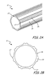
- FIG. 2A is a perspective view of a portion of the translating ram of FIG. 1A .
- FIG. 2B is a cross-sectional view of the translating ram of FIG. 2A .
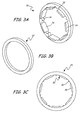
- FIG. 3A is a perspective view of a first element for a wiper for a translating ram.
- FIG. 3B is perspective view of a second element for a wiper for a translating ram.
- FIG. 3C is an end view of the wiper with the first and second elements of FIGS. 3A-3B .
- FIG. 4A is a perspective view of a portion of a translating ram with a first element of a wiper on the ram.
- FIG. 4B is a perspective view of the translating ram of FIG. 4A with the first element and a wiper second element on the ram.
- FIG. 4C is an end view of FIG. 4B .
- FIG. 1A is block diagram of a linear actuator with a translating ballscrew ram.
- FIG. 1B is block diagram of a linear actuator with a translating ballscrew ram fully extended.
- Actuator 10 includes translating ram 12, gearbox 13, motor 14, ballscrew shaft 16, ballscrew nut 18, recirculating ballspline 20, housing 22 and wiper 24.
- Translating ram 12 includes recessed portions 26 axially along the length of ram 12 (see FIGS. 2A-2B ).
- Motor 14 can be a permanent magnet electric motor with a brake. Motor 14 is connected to ballscrew shaft 16 through gearbox 13 and and causes shaft 16 to rotate. Ballscrew shaft 16 is connected to translating ram 12 through ballscrew nut 18. The rotation of ballscrew shaft 16 causes ballscrew nut 18 to move axially along ballscrew shaft 16. Translating ram 12 is connected to ballscrew nut 18 and moves with nut 18. This movement of nut 18 causes ram 12 to extend and retract relative to housing 22. Translating ram 12 moves through recirculating ballspline 20 and wiper 24, which are each held in place by housing 22. Recessed portions 26 of translating ram 12 fit together with recirculating ballspline 20, allowing axial movement of ram 12 and resisting rotation. Actuator 10 can include a second motor with brake, gears, or any other configuration of parts known in the art to add redundancy and/or tailor actuator 10 to the needs of a particular application.
- Actuator 10 causes translating ram 12 to extend or retract linearly as needed.
- Using recirculating ballspline 20 with translating ram 12 with recessed portions 26 gives ram 12 higher efficiencies than if ram 12 did not have recessed portions 26 (and a conventional bushing was used). This is due to the larger surface area contact of balls in recirculating ballspline 20 contacting recessed portions 26 of ram 12.
- Recirculating ballspline 20 with recessed portions 26 also allow low friction linear movement of ram 12 with anti-rotation torque transfer.
- recirculating ballspine 20 with recessed portions 26 are dependent upon the ball elements in recirculating ballspline 20 corresponding exactly with the dimensions of recessed portions 26.
- FIG. 2A is a perspective view of a portion of the translating ram 12 of FIG. 1A
- FIG. 2B is a cross-sectional view of the translating ram 12 of FIG. 2A
- Translating ram 12 includes recessed portions 26 and external surfaces 27.
- Translating ram 12 can be made of steel, stainless steel, titanium aluminum, plastic or any other material that fits the needs of actuator 10.
- Recessed portions 26 can run the length of translating ram 12 and can be in the configuration shown or can come in other configurations depending on the needs of the system. Recessed portions 26 can result in sharp edges between recessed portions 26 and external surfaces 27 in the cross-section of translating ram 12.
- Past wipers were configured to fit cylindrical rams without the sharp edged recessed portions 26. Because there were no sharp edged recessed portions, past wipers were generally easy to fit and manufacture.
- a conventional O-ring could be placed on prior art rams to form a seal. However, with the introduction of sharp edged recessed portions 26, conventional O-rings could no longer be used as wipers were required to fit tightly around a cross-section with sharp edges.
- FIG. 3A is a perspective view of first element 30 for wiper 24 for translating ram 12.
- FIG. 3B is an end view of second element 32 for wiper 24 for translating ram 12.
- FIG. 3C is an end view of wiper 24 with the first and second elements 30, 32 of FIGS. 3A-3B .
- Wiper 24 includes first element 30 and second element 32.
- First element 30 includes extensions 34 to support second element 32, portions 36 conforming to the recessed features of the translating ram; and gaps 38 to go over external cylindrical surface.
- Second element 32 conforms to the external surfaces of translating ram 12.
- second element 32 can be placed axially adjacent to first element 30 and over extensions 34 to form wiper 24.
- First element 30 and second element 32 can be made of an elastic material that has good sliding wear properties. The material properties helps wiper 24 seal against with ram 12, while allowing ram 12 translate through but not wear on wiper 24.
- An example of an appropriate material is Turcon®, a Polytetrafluoroethylene made by Trelleborg Sealing Solutions.
- Wiper 24 is able to seal even around sharp corners by including first element 30 to seal recessed portions 26 and placing it adjacent to second element 30 conforming to outer portions 27 of translating ram 12. The use of two elements, 30 and 32 allow wiper 24 to seal both recessed portions and sharp corners generated by recessed portions 26 on ram 12.
- FIG. 4A is a perspective view of a portion of translating ram 12 with first element 30 of wiper 24 on ram 12.
- FIG. 4B is a perspective view of translating ram 12 of FIG. 4A with the first element 30 and second element 32 on the ram 12.
- FIG. 4C is an end view of FIG. 4B .
- Translating ram 12 includes recessed portions 26 and external surfaces 27.
- Wiper 24 includes first element 30 (with extensions 34 and portions 36 conforming to recessed features of translating ram 12) and second element 32.
- First element 30 of wiper 24 is placed on translating ram 12 so that portions 36 conforming to recessed features fit with recessed portions 26 of ram 12. Second element 32 is then placed axially adjacent to first element 30 to form wiper 24. Second element 32 fits over first element 30 and is supported by extensions 34 of first element 30. Wiper 24 forms a cross-sectional seal on translating ram 12, with portions 36 sealing recessed portions 26 of translating ram 12 and second element 32 fitting with first element 30 to seal over sharp edges of ram 12. Wiper 24 therefore works to prevent dirt or other debris from entering into actuator 10 as translating ram 12 is extended or retracted into housing 22.
- wiper 24 By forming wiper 24 with a first element 30 conforming to the recessed features of the translating ram and a second element 32 conforming to the external surface of the translating ram, wiper 24 is able to form a seal over sharp edges and recessed portions 26 of translating ram 12. Wiper 24 allows the use and benefits of a translating ram with recessed portions while keeping dirt and debris out of the actuator 10 housing 22 and recirculating ballspline 20 (or other device which uses ram 12). The sealing against dirt and debris can prevent damage or a reduction in the life of the actuator.
- wiper 24 has been discussed in relation to use in an actuator with a recirculating ballspline, it can be used in with any device where a translating ram with recessed portions is used. Additionally, the configuration of recessed portions of translating ram and complimentary configurations of portions of wiper 24 to seal ram can be differed depending on needs of the system.
- first element and second element may just sit adjacent to each other and may be held in place by a housing.
- first element and second element may just sit adjacent to each other and may be held in place by a housing.
- Other embodiments could include a compression device, such as an o-ring, a spring, a clamp, etc. The compression device could fit around the outside diameter of wiper 24 and could provide a higher scraping force between wiper 24 and translating ram 12.
Landscapes
- Engineering & Computer Science (AREA)
- General Engineering & Computer Science (AREA)
- Mechanical Engineering (AREA)
- Transmission Devices (AREA)
Abstract
Description
- The present invention relates to linear actuators and more particularly to translating rams with recessed portions.
- Throughout history, engineers have invented mechanisms that have had the capability to move objects. One particular category of these mechanisms is referred to as an actuator. Actuators can be designed to move objects in a rotary motion, or in a linear motion. A rotary actuator is simply a gearbox that either increases or decreases the rotational speed of a prime mover, typically a hydraulic motor, an internal combustion engine, a turbine engine, or an electric motor, to provide a desired level of rotational speed and torque at the output of the machine. Some examples of rotary actuators include: gearboxes, transmissions, differentials, hydraulic rotary actuators, and rotary electro-mechanical actuators. Linear actuators are machines designed to provide force and linear displacement to an object. Some examples of linear actuators include: rack & pinion actuators, hydraulic rams, ball screw actuators, and crank arm actuators.
- Historically, hydraulic/pneumatic motors and hydraulic/pneumatic rams have been the primary source of power for both linear and rotary actuators. Hydraulic systems offer many advantages to the designer. These advantages include: high power density, accurate position control, low inertia (for high frequency response), and overload protection (via pressure relief valves).
- In the last several decades, engineers have started to replace hydraulic/pneumatic actuation systems with electro-mechanical actuation systems. Electro-mechanical actuators ("EMAs") offer increased efficiency over their hydraulic and pneumatic counterparts and can eliminate the fire hazards and leakage potentials associated with the hydraulic fluids used in hydraulic actuation systems. One application for linear EMAs is on a space craft thrust vector control system. These EMAs can include redundant architecture to prevent single point failures.
- A wiper for a translating ram with recessed features includes a first element conforming to the recessed features of the translating ram; and a second element conforming to the external surface of the translating ram. The first element and second element conform to the cross-section of the translating ram when placed axially adjacent.
- A method of manufacturing a wiper for a translating ram with recessed portions includes forming a first element to conform to the recessed portions of the translating ram; and forming a second element to fit axially adjacent to the first element and to conform to the external surface of the translating ram.
-
FIG. 1A is block diagram of a linear actuator with a translating ballscrew ram. -
FIG. 1B is block diagram of a linear actuator with a translating ballscrew ram fully extended. -
FIG. 2A is a perspective view of a portion of the translating ram ofFIG. 1A . -
FIG. 2B is a cross-sectional view of the translating ram ofFIG. 2A . -
FIG. 3A is a perspective view of a first element for a wiper for a translating ram. -
FIG. 3B is perspective view of a second element for a wiper for a translating ram. -
FIG. 3C is an end view of the wiper with the first and second elements ofFIGS. 3A-3B . -
FIG. 4A is a perspective view of a portion of a translating ram with a first element of a wiper on the ram. -
FIG. 4B is a perspective view of the translating ram ofFIG. 4A with the first element and a wiper second element on the ram. -
FIG. 4C is an end view ofFIG. 4B . -
FIG. 1A is block diagram of a linear actuator with a translating ballscrew ram.FIG. 1B is block diagram of a linear actuator with a translating ballscrew ram fully extended.Actuator 10 includes translatingram 12,gearbox 13,motor 14,ballscrew shaft 16,ballscrew nut 18, recirculatingballspline 20,housing 22 andwiper 24. Translatingram 12 includesrecessed portions 26 axially along the length of ram 12 (seeFIGS. 2A-2B ). -
Motor 14 can be a permanent magnet electric motor with a brake.Motor 14 is connected toballscrew shaft 16 throughgearbox 13 and and causesshaft 16 to rotate. Ballscrewshaft 16 is connected to translatingram 12 throughballscrew nut 18. The rotation ofballscrew shaft 16 causesballscrew nut 18 to move axially alongballscrew shaft 16. Translatingram 12 is connected toballscrew nut 18 and moves withnut 18. This movement ofnut 18 causesram 12 to extend and retract relative tohousing 22. Translatingram 12 moves through recirculatingballspline 20 andwiper 24, which are each held in place byhousing 22. Recessedportions 26 of translatingram 12 fit together withrecirculating ballspline 20, allowing axial movement ofram 12 and resisting rotation. Actuator 10 can include a second motor with brake, gears, or any other configuration of parts known in the art to add redundancy and/ortailor actuator 10 to the needs of a particular application. -
Actuator 10 causes translatingram 12 to extend or retract linearly as needed. Usingrecirculating ballspline 20 with translatingram 12 withrecessed portions 26 givesram 12 higher efficiencies than ifram 12 did not have recessed portions 26 (and a conventional bushing was used). This is due to the larger surface area contact of balls in recirculatingballspline 20 contacting recessedportions 26 ofram 12. Recirculatingballspline 20 with recessedportions 26 also allow low friction linear movement ofram 12 with anti-rotation torque transfer. - The use and benefits of recirculating
ballspine 20 with recessedportions 26 are dependent upon the ball elements in recirculatingballspline 20 corresponding exactly with the dimensions of recessedportions 26. As translatingram 12 extends out and then retracts, there is a danger of dirt or other debris becoming stuck onram 12 and enteringrecirculating ballspline 20. That foreign debris can prevent the low friction movement ofram 12, and may even cause translatingram 12 to jam up.Wiper 24 fits overram 12 to prevent any dirt or debris from enteringrecirculating ballspline 20 as translatingram 12 retracts intohousing 22. -
FIG. 2A is a perspective view of a portion of the translatingram 12 ofFIG. 1A , andFIG. 2B is a cross-sectional view of the translatingram 12 ofFIG. 2A . Translatingram 12 includes recessedportions 26 andexternal surfaces 27. - Translating
ram 12 can be made of steel, stainless steel, titanium aluminum, plastic or any other material that fits the needs ofactuator 10. Recessedportions 26 can run the length of translatingram 12 and can be in the configuration shown or can come in other configurations depending on the needs of the system. Recessedportions 26 can result in sharp edges between recessedportions 26 andexternal surfaces 27 in the cross-section of translatingram 12. Past wipers were configured to fit cylindrical rams without the sharp edged recessedportions 26. Because there were no sharp edged recessed portions, past wipers were generally easy to fit and manufacture. A conventional O-ring could be placed on prior art rams to form a seal. However, with the introduction of sharp edged recessedportions 26, conventional O-rings could no longer be used as wipers were required to fit tightly around a cross-section with sharp edges. -
FIG. 3A is a perspective view offirst element 30 forwiper 24 for translatingram 12.FIG. 3B is an end view ofsecond element 32 forwiper 24 for translatingram 12.FIG. 3C is an end view ofwiper 24 with the first andsecond elements FIGS. 3A-3B . -
Wiper 24 includesfirst element 30 andsecond element 32.First element 30 includesextensions 34 to supportsecond element 32,portions 36 conforming to the recessed features of the translating ram; andgaps 38 to go over external cylindrical surface.Second element 32 conforms to the external surfaces of translatingram 12. - As seen in
FIG. 3C ,second element 32 can be placed axially adjacent tofirst element 30 and overextensions 34 to formwiper 24.First element 30 andsecond element 32 can be made of an elastic material that has good sliding wear properties. The material properties helpswiper 24 seal against withram 12, while allowingram 12 translate through but not wear onwiper 24. An example of an appropriate material is Turcon®, a Polytetrafluoroethylene made by Trelleborg Sealing Solutions. - Past attempts at making wipers for translating rams with recessed portions were unsuccessful due to the inability to machine or cast internal sharp corners. Machining or casting always involved some finite radius on the cutting tool used or the casting, resulting in a wiper with gaps between it and the translating ram sharp corners.
Wiper 24 is able to seal even around sharp corners by includingfirst element 30 to seal recessedportions 26 and placing it adjacent tosecond element 30 conforming toouter portions 27 of translatingram 12. The use of two elements, 30 and 32 allowwiper 24 to seal both recessed portions and sharp corners generated by recessedportions 26 onram 12. -
FIG. 4A is a perspective view of a portion of translatingram 12 withfirst element 30 ofwiper 24 onram 12.FIG. 4B is a perspective view of translatingram 12 ofFIG. 4A with thefirst element 30 andsecond element 32 on theram 12.FIG. 4C is an end view ofFIG. 4B . Translatingram 12 includes recessedportions 26 andexternal surfaces 27.Wiper 24 includes first element 30 (withextensions 34 andportions 36 conforming to recessed features of translating ram 12) andsecond element 32. -
First element 30 ofwiper 24 is placed on translatingram 12 so thatportions 36 conforming to recessed features fit with recessedportions 26 ofram 12.Second element 32 is then placed axially adjacent tofirst element 30 to formwiper 24.Second element 32 fits overfirst element 30 and is supported byextensions 34 offirst element 30.Wiper 24 forms a cross-sectional seal on translatingram 12, withportions 36 sealing recessedportions 26 of translatingram 12 andsecond element 32 fitting withfirst element 30 to seal over sharp edges ofram 12.Wiper 24 therefore works to prevent dirt or other debris from entering intoactuator 10 as translatingram 12 is extended or retracted intohousing 22. - By forming
wiper 24 with afirst element 30 conforming to the recessed features of the translating ram and asecond element 32 conforming to the external surface of the translating ram,wiper 24 is able to form a seal over sharp edges and recessedportions 26 of translatingram 12.Wiper 24 allows the use and benefits of a translating ram with recessed portions while keeping dirt and debris out of theactuator 10housing 22 and recirculating ballspline 20 (or other device which uses ram 12). The sealing against dirt and debris can prevent damage or a reduction in the life of the actuator. - While
wiper 24 has been discussed in relation to use in an actuator with a recirculating ballspline, it can be used in with any device where a translating ram with recessed portions is used. Additionally, the configuration of recessed portions of translating ram and complimentary configurations of portions ofwiper 24 to seal ram can be differed depending on needs of the system. - While a wiper with a
first element 30 withextensions 34 to supportsecond element 32 is shown,extensions 34 are not required, and first element and second element may just sit adjacent to each other and may be held in place by a housing. In an alternative embodiment, there may be some interlocking of first element and second element. Other embodiments could include a compression device, such as an o-ring, a spring, a clamp, etc. The compression device could fit around the outside diameter ofwiper 24 and could provide a higher scraping force betweenwiper 24 and translatingram 12. - While the invention has been described with reference to an exemplary embodiment(s), it will be understood by those skilled in the art that various changes may be made and equivalents may be substituted for elements thereof without departing from the scope of the invention which is defined by the appended claims. In addition, many modifications may be made to adapt a particular situation or material to the teachings of the invention without departing from the essential scope thereof. Therefore, it is intended that the invention not be limited to the particular embodiment(s) disclosed, but that the invention will include all embodiments falling within the scope of the appended claims.
Claims (15)
- A wiper (24) for a translating ram (12) with recessed features (26), an external surface (27) and sharp edges, the wiper comprising:a first element (30) conforming to the recessed features of the translating ram; anda second element (32) conforming to the external surface of the translating ram, wherein the first element and second element conform to the cross-section of the translating ram when placed axially adjacent.
- The wiper of claim 1, wherein the first element (30) further comprises a plurality of extensions (34) extending axially for the second element (32) to stretch over and be supported by when placed axially adjacent to the first element.
- The wiper of claim 1, wherein the first element (30) further comprises extensions (34) extending axially to connect to the second element (32) when placed axially adjacent to the first element (30).
- The wiper of claim 1, 2 or 3, wherein the first element (30) and the second element (32) are held axially adjacent to each other by the extensions (34).
- The wiper of any preceding claim, wherein the first element (30) and second element (32) together seal the cross-section of the translating ram (12) to prevent ingress of debris as the translating ram moves through the wiper (24).
- The wiper of any preceding claim, wherein the first element (30) is made of an elastic material; and/or
wherein the second element (32) is made of an elastic material. - The wiper of any preceding claim, wherein the first element (30) and the second element (32) fit together to seal over the sharp edges of the ram (12).
- An actuator (10) comprising:a housing (22);a translating ram (12) with recessed features (26) to move in and out of the housing; anda wiper (24) as claimed in any preceding claim, said wiper being provided on the translating ram in the housing and adjacent to a recirculating ballspline (20).
- The actuator of claim 8, wherein the first element (30) further comprises extensions (34) to support the second element (32).
- The actuator of claim 8 or 9, wherein the wiper (24) seals the cross-section of the translating ram (12) to prevent ingress of debris into the recirculating ballspline (20) as the translating ram moves in and out of the housing (22).
- The actuator of claim 8, 9 or 10, wherein the wiper (24) is held in place by the housing (22).
- The actuator of claim 8, 9, 10 or 11, wherein the recirculating ballspline (20) is in the housing (22) adjacent to the wiper (24) for the translating ram (12) to move through.
- A method of manufacturing a wiper (24) for a translating ram (12) with recessed portions (26), the method comprising:forming a first element (30) to conform to the recessed portions of the translating ram; andforming a second element (32) to fit axially adjacent to the first element and to conform to an external surface (27) of the translating ram.
- The method of claim 13, wherein the step of forming the first element (30) further comprises forming extensions (34) to support the second element (32).
- The method of claim 13 or 14, wherein the first element (30) and second element (32) are formed of an elastic material.
Applications Claiming Priority (1)
| Application Number | Priority Date | Filing Date | Title |
|---|---|---|---|
| US13/185,945 US8904891B2 (en) | 2011-07-19 | 2011-07-19 | Wiper for translating ram |
Publications (1)
| Publication Number | Publication Date |
|---|---|
| EP2549145A1 true EP2549145A1 (en) | 2013-01-23 |
Family
ID=46125274
Family Applications (1)
| Application Number | Title | Priority Date | Filing Date |
|---|---|---|---|
| EP12168587A Withdrawn EP2549145A1 (en) | 2011-07-19 | 2012-05-18 | Wiper for translating ram |
Country Status (2)
| Country | Link |
|---|---|
| US (1) | US8904891B2 (en) |
| EP (1) | EP2549145A1 (en) |
Cited By (1)
| Publication number | Priority date | Publication date | Assignee | Title |
|---|---|---|---|---|
| US10227811B2 (en) | 2014-12-02 | 2019-03-12 | Hi-Lex Corporation | Extensible/contractible driving device and openable body opening/closing device |
Families Citing this family (2)
| Publication number | Priority date | Publication date | Assignee | Title |
|---|---|---|---|---|
| ITRM20120587A1 (en) * | 2012-11-22 | 2014-05-23 | Umbra Cuscinetti Spa | LINEAR ELECTROMECHANICAL ACTUATOR WITH INTEGRATED ANTI-ROTATION. |
| US9512910B2 (en) * | 2013-02-19 | 2016-12-06 | Honeywell International Inc. | Actuator including handling-proof position feedback mechanism |
Citations (3)
| Publication number | Priority date | Publication date | Assignee | Title |
|---|---|---|---|---|
| JPH0544810A (en) * | 1991-08-19 | 1993-02-23 | Nippon Seiko Kk | Dustproof seal for ball screws |
| US20020144560A1 (en) * | 2001-04-05 | 2002-10-10 | Thk Co., Ltd. | Seal for ball screw and ball screw utilizing same |
| US20110169357A1 (en) * | 2010-01-14 | 2011-07-14 | Gieras Jacek F | Compact electromechanical actuator |
Family Cites Families (13)
| Publication number | Priority date | Publication date | Assignee | Title |
|---|---|---|---|---|
| US2403092A (en) | 1943-02-19 | 1946-07-02 | Lear Inc | Linear actuator |
| US2778344A (en) * | 1953-11-06 | 1957-01-22 | Thompson Prod Inc | Pneumatic powered linear actuator |
| BE793196A (en) | 1971-12-23 | 1973-04-16 | Clark Equipment Co | CYLINDER WITH LINEAR MOVEMENT OF CYLINDER AND PISTON TYPE |
| US4179944A (en) | 1977-06-27 | 1979-12-25 | United Technologies Corporation | Fail safe redundant actuator |
| US4407511A (en) | 1981-07-24 | 1983-10-04 | General Motors Corporation | Seal and scraper assembly |
| US4753071A (en) | 1985-12-23 | 1988-06-28 | Sundstrand Corporation | Self-powered rotating-cylinder type linear actuator utilizing rotation-generated centrifugal head for piston positioning |
| US5144851A (en) | 1991-08-01 | 1992-09-08 | Sundstrand Corp. | Jam tolerant linear actuator |
| US5269343A (en) * | 1992-04-10 | 1993-12-14 | Elkhart Brass Mfg. Co., Inc. | Valve actuator |
| US5398780A (en) | 1993-02-19 | 1995-03-21 | Sundstrand Corporation | Linear actuator with speed controlling brake |
| US6237434B1 (en) | 1998-08-31 | 2001-05-29 | Thompson Saginaw Ball Screw Company, Llc. | Ball screw and nut assembly with a nut having a preloaded wiper thread and method of its manufacture and operation |
| US7342306B2 (en) | 2005-12-22 | 2008-03-11 | International Business Machines Corporation | High performance reworkable heatsink and packaging structure with solder release layer |
| US7810208B2 (en) | 2007-01-17 | 2010-10-12 | Hampton Hydraulics, Llc | Combined axially and radially loaded dirt excluder |
| US7958593B2 (en) | 2007-07-20 | 2011-06-14 | Lhr Technologies, Inc. | Wiper mechanism |
-
2011
- 2011-07-19 US US13/185,945 patent/US8904891B2/en active Active
-
2012
- 2012-05-18 EP EP12168587A patent/EP2549145A1/en not_active Withdrawn
Patent Citations (3)
| Publication number | Priority date | Publication date | Assignee | Title |
|---|---|---|---|---|
| JPH0544810A (en) * | 1991-08-19 | 1993-02-23 | Nippon Seiko Kk | Dustproof seal for ball screws |
| US20020144560A1 (en) * | 2001-04-05 | 2002-10-10 | Thk Co., Ltd. | Seal for ball screw and ball screw utilizing same |
| US20110169357A1 (en) * | 2010-01-14 | 2011-07-14 | Gieras Jacek F | Compact electromechanical actuator |
Cited By (1)
| Publication number | Priority date | Publication date | Assignee | Title |
|---|---|---|---|---|
| US10227811B2 (en) | 2014-12-02 | 2019-03-12 | Hi-Lex Corporation | Extensible/contractible driving device and openable body opening/closing device |
Also Published As
| Publication number | Publication date |
|---|---|
| US8904891B2 (en) | 2014-12-09 |
| US20130019420A1 (en) | 2013-01-24 |
Similar Documents
| Publication | Publication Date | Title |
|---|---|---|
| EP2333377A1 (en) | Linear actuator with ball bearing spline | |
| KR102084020B1 (en) | Flat wave gear device | |
| EP3467347B1 (en) | Linear actuator | |
| WO2008144420A2 (en) | Helical spline actuators | |
| US8904891B2 (en) | Wiper for translating ram | |
| US20190101208A1 (en) | Ballscrew actuators | |
| JP6612321B2 (en) | Car brake actuator | |
| CN118030794A (en) | Electric linear actuator | |
| JP5853616B2 (en) | Actuator and manufacturing method thereof | |
| EP3486501B1 (en) | Actuator assembly having self-lubricating components | |
| KR102485896B1 (en) | Electric cylinder apparatus provided with improved bearing cover assembly structure of screw shaft | |
| JP7498769B2 (en) | Linear Actuator | |
| EP4165323B1 (en) | Inverted ball screw actuator | |
| US12292063B2 (en) | Linear actuator | |
| CN112413075A (en) | Ball Screw Seals | |
| CN218733659U (en) | Electrodynamic linear drive with radial compensation | |
| CN204239649U (en) | Ball screw | |
| CN107208765A (en) | Nut, actuator and manufacture method for linear actuators | |
| NO344441B1 (en) | Linear Actuator | |
| EP3054193A1 (en) | A gasket for recirculating ball screw actuators | |
| KR20220090283A (en) | Electric cylinder apparatus provided with improved holding brake structure | |
| JP2020023968A5 (en) | ||
| CN219565215U (en) | Ball circulation assembly for power steering gear and power steering gear | |
| KR20170032933A (en) | Heavy Duty Mechenical Multistep Power Cylinder | |
| GB2616877A (en) | Linear actuator and braking system |
Legal Events
| Date | Code | Title | Description |
|---|---|---|---|
| PUAI | Public reference made under article 153(3) epc to a published international application that has entered the european phase |
Free format text: ORIGINAL CODE: 0009012 |
|
| AK | Designated contracting states |
Kind code of ref document: A1 Designated state(s): AL AT BE BG CH CY CZ DE DK EE ES FI FR GB GR HR HU IE IS IT LI LT LU LV MC MK MT NL NO PL PT RO RS SE SI SK SM TR |
|
| AX | Request for extension of the european patent |
Extension state: BA ME |
|
| 17P | Request for examination filed |
Effective date: 20130723 |
|
| RBV | Designated contracting states (corrected) |
Designated state(s): AL AT BE BG CH CY CZ DE DK EE ES FI FR GB GR HR HU IE IS IT LI LT LU LV MC MK MT NL NO PL PT RO RS SE SI SK SM TR |
|
| STAA | Information on the status of an ep patent application or granted ep patent |
Free format text: STATUS: THE APPLICATION HAS BEEN WITHDRAWN |
|
| 18W | Application withdrawn |
Effective date: 20140113 |