EP2549122A1 - Centrifugal compressor and turbo supercharger - Google Patents
Centrifugal compressor and turbo supercharger Download PDFInfo
- Publication number
- EP2549122A1 EP2549122A1 EP10847901A EP10847901A EP2549122A1 EP 2549122 A1 EP2549122 A1 EP 2549122A1 EP 10847901 A EP10847901 A EP 10847901A EP 10847901 A EP10847901 A EP 10847901A EP 2549122 A1 EP2549122 A1 EP 2549122A1
- Authority
- EP
- European Patent Office
- Prior art keywords
- housing
- diffuser
- wall portion
- axis
- vane
- Prior art date
- Legal status (The legal status is an assumption and is not a legal conclusion. Google has not performed a legal analysis and makes no representation as to the accuracy of the status listed.)
- Withdrawn
Links
Images


Classifications
-
- F—MECHANICAL ENGINEERING; LIGHTING; HEATING; WEAPONS; BLASTING
- F04—POSITIVE - DISPLACEMENT MACHINES FOR LIQUIDS; PUMPS FOR LIQUIDS OR ELASTIC FLUIDS
- F04D—NON-POSITIVE-DISPLACEMENT PUMPS
- F04D27/00—Control, e.g. regulation, of pumps, pumping installations or pumping systems specially adapted for elastic fluids
- F04D27/002—Control, e.g. regulation, of pumps, pumping installations or pumping systems specially adapted for elastic fluids by varying geometry within the pumps, e.g. by adjusting vanes
-
- F—MECHANICAL ENGINEERING; LIGHTING; HEATING; WEAPONS; BLASTING
- F04—POSITIVE - DISPLACEMENT MACHINES FOR LIQUIDS; PUMPS FOR LIQUIDS OR ELASTIC FLUIDS
- F04D—NON-POSITIVE-DISPLACEMENT PUMPS
- F04D29/00—Details, component parts, or accessories
- F04D29/40—Casings; Connections of working fluid
- F04D29/42—Casings; Connections of working fluid for radial or helico-centrifugal pumps
- F04D29/44—Fluid-guiding means, e.g. diffusers
- F04D29/441—Fluid-guiding means, e.g. diffusers especially adapted for elastic fluid pumps
- F04D29/444—Bladed diffusers
-
- F—MECHANICAL ENGINEERING; LIGHTING; HEATING; WEAPONS; BLASTING
- F01—MACHINES OR ENGINES IN GENERAL; ENGINE PLANTS IN GENERAL; STEAM ENGINES
- F01D—NON-POSITIVE DISPLACEMENT MACHINES OR ENGINES, e.g. STEAM TURBINES
- F01D25/00—Component parts, details, or accessories, not provided for in, or of interest apart from, other groups
- F01D25/24—Casings; Casing parts, e.g. diaphragms, casing fastenings
-
- F—MECHANICAL ENGINEERING; LIGHTING; HEATING; WEAPONS; BLASTING
- F02—COMBUSTION ENGINES; HOT-GAS OR COMBUSTION-PRODUCT ENGINE PLANTS
- F02B—INTERNAL-COMBUSTION PISTON ENGINES; COMBUSTION ENGINES IN GENERAL
- F02B37/00—Engines characterised by provision of pumps driven at least for part of the time by exhaust
- F02B37/12—Control of the pumps
- F02B37/24—Control of the pumps by using pumps or turbines with adjustable guide vanes
-
- F—MECHANICAL ENGINEERING; LIGHTING; HEATING; WEAPONS; BLASTING
- F02—COMBUSTION ENGINES; HOT-GAS OR COMBUSTION-PRODUCT ENGINE PLANTS
- F02D—CONTROLLING COMBUSTION ENGINES
- F02D21/00—Controlling engines characterised by their being supplied with non-airborne oxygen or other non-fuel gas
- F02D21/06—Controlling engines characterised by their being supplied with non-airborne oxygen or other non-fuel gas peculiar to engines having other non-fuel gas added to combustion air
- F02D21/08—Controlling engines characterised by their being supplied with non-airborne oxygen or other non-fuel gas peculiar to engines having other non-fuel gas added to combustion air the other gas being the exhaust gas of engine
-
- F—MECHANICAL ENGINEERING; LIGHTING; HEATING; WEAPONS; BLASTING
- F02—COMBUSTION ENGINES; HOT-GAS OR COMBUSTION-PRODUCT ENGINE PLANTS
- F02D—CONTROLLING COMBUSTION ENGINES
- F02D23/00—Controlling engines characterised by their being supercharged
-
- F—MECHANICAL ENGINEERING; LIGHTING; HEATING; WEAPONS; BLASTING
- F02—COMBUSTION ENGINES; HOT-GAS OR COMBUSTION-PRODUCT ENGINE PLANTS
- F02D—CONTROLLING COMBUSTION ENGINES
- F02D41/00—Electrical control of supply of combustible mixture or its constituents
- F02D41/02—Circuit arrangements for generating control signals
- F02D41/021—Introducing corrections for particular conditions exterior to the engine
- F02D41/0235—Introducing corrections for particular conditions exterior to the engine in relation with the state of the exhaust gas treating apparatus
- F02D41/027—Introducing corrections for particular conditions exterior to the engine in relation with the state of the exhaust gas treating apparatus to purge or regenerate the exhaust gas treating apparatus
- F02D41/029—Introducing corrections for particular conditions exterior to the engine in relation with the state of the exhaust gas treating apparatus to purge or regenerate the exhaust gas treating apparatus the exhaust gas treating apparatus being a particulate filter
-
- F—MECHANICAL ENGINEERING; LIGHTING; HEATING; WEAPONS; BLASTING
- F04—POSITIVE - DISPLACEMENT MACHINES FOR LIQUIDS; PUMPS FOR LIQUIDS OR ELASTIC FLUIDS
- F04D—NON-POSITIVE-DISPLACEMENT PUMPS
- F04D27/00—Control, e.g. regulation, of pumps, pumping installations or pumping systems specially adapted for elastic fluids
- F04D27/02—Surge control
- F04D27/0246—Surge control by varying geometry within the pumps, e.g. by adjusting vanes
-
- F—MECHANICAL ENGINEERING; LIGHTING; HEATING; WEAPONS; BLASTING
- F04—POSITIVE - DISPLACEMENT MACHINES FOR LIQUIDS; PUMPS FOR LIQUIDS OR ELASTIC FLUIDS
- F04D—NON-POSITIVE-DISPLACEMENT PUMPS
- F04D29/00—Details, component parts, or accessories
- F04D29/40—Casings; Connections of working fluid
- F04D29/42—Casings; Connections of working fluid for radial or helico-centrifugal pumps
- F04D29/44—Fluid-guiding means, e.g. diffusers
- F04D29/46—Fluid-guiding means, e.g. diffusers adjustable
- F04D29/462—Fluid-guiding means, e.g. diffusers adjustable especially adapted for elastic fluid pumps
-
- F—MECHANICAL ENGINEERING; LIGHTING; HEATING; WEAPONS; BLASTING
- F02—COMBUSTION ENGINES; HOT-GAS OR COMBUSTION-PRODUCT ENGINE PLANTS
- F02D—CONTROLLING COMBUSTION ENGINES
- F02D41/00—Electrical control of supply of combustible mixture or its constituents
- F02D41/0002—Controlling intake air
- F02D41/0007—Controlling intake air for control of turbo-charged or super-charged engines
-
- F—MECHANICAL ENGINEERING; LIGHTING; HEATING; WEAPONS; BLASTING
- F05—INDEXING SCHEMES RELATING TO ENGINES OR PUMPS IN VARIOUS SUBCLASSES OF CLASSES F01-F04
- F05D—INDEXING SCHEME FOR ASPECTS RELATING TO NON-POSITIVE-DISPLACEMENT MACHINES OR ENGINES, GAS-TURBINES OR JET-PROPULSION PLANTS
- F05D2250/00—Geometry
- F05D2250/50—Inlet or outlet
- F05D2250/52—Outlet
Definitions
- the present invention relates to a centrifugal compressor provided with a movable vane moving in and out of a diffuser passage, and a turbo supercharger having the centrifugal compressor.
- Patent Literature 1 JP-A-2001-329996
- the vane collides against an opposed side diffuser wall when the vane moves to reach the projected position. Thereby, there is a possibility that the vane is deformed in this moment and a part of the opposed side diffuser wall which has collided against the vane wears away.
- a clearance is formed between the opposed side diffuser wall and the vane when the vane reaches the projected position.
- the size of the clearance is decided by a length of the vane projecting in the diffuser at the projected position and a distance between the diffuser walls.
- an object of the present invention is to provide a centrifugal compressor and a turbo supercharger, which can decrease the number of portions to be the sizes of which are managed for decreasing a size of a clearance between a vane existing at a projected position and a diffuser wall.
- a centrifugal compressor of the present invention comprises: a housing assembly that includes a first housing which supports a rotating shaft so as to be rotatable about an axis, the rotating shaft having an impeller on an end portion of itself, and a second housing which houses the impeller inside and is assembled with the first housing so as to be aligned in the direction of the axis with the first housing, wherein a diffuser serving as a passage space communicated with an exit side of the impeller is formed by a first diffuser wall portion of a first housing side and a second diffuser wall portion of a second housing side on outer periphery of the impeller, and a movable vane that includes a base portion which is arranged in a storage chamber provided in the first diffuser wall portion and has a facing surface opposing to the second diffuser wall portion, and vane portions which project from the facing surface to a second diffuser wall portion side, wherein the movable vane is movable in the direction of the axis between a projected position where the facing surface contacts
- the positioning surface is flush with the fastening surface.
- the size of a clearance between the movable vane in the projected position and the second diffuser wall portion is decided by two sizes which are the size of a distance in the direction of the axis between the fastening surface and the second diffuser wall portion and the size of a projecting length of the vane portion in the direction of the axis from the base portion.
- the fastening surface may be attached to the mounting surface so that a part of the fastening surface covers at least a part of the concave portion, and the positioning surface may be the part of the fastening surface covering the concave portion.
- a turbo supercharger of the present invention comprises the centrifugal compressor mentioned above and a turbine, wherein the centrifugal compressor is provided to an intake passage of an internal combustion engine and the turbine is provided to an exhaust passage of the internal combustion engine, the turbine recovers exhaust energy of the internal combustion engine, and the turbo supercharger supercharges the internal combustion engine by driving to rotate the impeller of the centrifugal compressor by recovered exhaust energy.
- turbo supercharger of the present invention since the turbo supercharger has the above mentioned centrifugal compressor, it is possible to decrease the number of the portions to be managed about the size for decreasing the size of the clearance between the movable vane in the projected position and the second diffuser wall portion to two. Thereby, it is possible to decrease the size of the clearance while forming the clearance between the movable vane in the projected position and the second diffuser wall portion. Accordingly, it is possible to suppress decreasing a supercharging efficiency when the movable vane reaches the projected position.
- Fig. 1 shows a main part of a turbo supercharger in which a centrifugal compressor according to a first embodiment of the present invention is incorporated.
- the turbo supercharger 1 is attached to an internal combustion engine that is mounted on a vehicle as a traveling power source.
- the turbo supercharger 1 includes a centrifugal compressor 2 and a turbine (not shown) .
- the turbine is similar to a turbine of a well known turbo supercharger. Thereby, illustration and description thereof will be omitted.
- the compressor 2 has a housing assembly 3 and an impeller 4 housed in the housing assembly 3.
- the housing assembly 3 has a wheel chamber 5 in which the impeller 4 is housed, a diffuser 6 provided outward in a radial direction of the wheel chamber 4 as a passage space communicated with the exit side of the impeller 4, and a scrolled scroll chamber 7 provided outward in a radial direction of the diffuser 6 and communicated with the diffuser 6.
- the impeller 4 is fixed to an end portion of a rotating shaft 8 by a nut 8a, and rotates with the rotating shaft 8.
- a turbine wheel of the turbine is attached to the other end portion of the rotating shaft 8.
- the housing assembly 3 has a bearing housing 9 serving as a first housing and a compressor housing 10 serving as a second housing.
- the bearing housing 9 supports the rotating shaft 8 so as to be rotatable about an axis Ax.
- the compressor housing 10 houses the impeller 4 inside so as to be rotatable about the axis Ax, and is assembled with the bearing housing 9 so as to be aligned in the direction of the axis Ax with it.
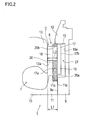
- Fig. 2 is an enlarged view of a part around the diffuser 6.
- the bearing housing 9 has a mounting surface 9a located in a direction perpendicular to the direction of the axis Ax.
- the mounting surface 9a is arranged outward in the radial direction further than the diffuser 6.
- the compressor housing 10 is provided with an affixing portion 11 mounted to the mounting surface 9a.
- the affixing portion 11 is provided with a fastening surface 11a located in a direction perpendicular to the direction of the axis Ax as with the mounting surface 9a.
- the compressor housing 10 is assembled with the bearing housing 9 so that the fastening surface 11a contacts the mounting surface 9a.
- the diffuser 6 is formed by a first diffuser wall portion 12 which is arranged on a side of the bearing housing 9 and a second diffuser wall portion 13 which is arranged on a side of the compressor housing 10. These diffuser wall portions 12, 13 are arranged so as to be aligned in the direction of the axis Ax, and to be opposed to each other.
- the second diffuser wall portion 13 has a wall surface 13a forming the diffuser 6.
- the wall surface 13a is arranged at a position which is concaved at a distance L1 in the direction of the axis Ax from the fastening surface 11a.
- the first diffuser wall portion 12 is provided with a movable vane mechanism 14.
- the movable vane mechanism 14 has a movable vane 15 and a driving apparatus 16 which drives the movable vane 15 in the direction of the axis Ax.
- the driving apparatus 16 may be a known apparatus to drive the movable vane 15 in the direction of the axis Ax by transmitting a power of an actuator (not shown) to the movable vane 15 via a link mechanism and the like. Thereby, a detailed description thereof will be omitted.
- Fig. 3 is an enlarged view of the movable vane 15.
- the movable vane 15 has a hollow disk shaped base portion 17 and a plurality of vane portions 18 projected from the base portion 17.
- Each vane portion 18 projects toward the second diffuser wall portion 13 from the base portion 17.
- the base portion 17 has a facing surface 17a opposing to the second diffuser wall portion 13 and located in a direction perpendicular to the direction of the axis Ax.
- the vane portion 18 projects in the direction of the axis Ax from the facing surface 17a.
- As a projecting length L2 of the vane portions 18, set is a value which is slightly smaller than the distance L1 between the wall surface 13a of the second diffuser wall portion 13 and the fastening surface 11a.
- the bearing housing 9 is provided with a concave portion 19 arranging inward in the radial direction of the mounting surface 9a and hollowing in the direction of the axis Ax from the mounting surface 9a.
- the concave portion 19 is formed around the entire outer periphery of the impeller 4.
- a diffuser plate 20 is mounted on the bearing housing 9 so as to cover the concave portion 19. As shown in this figure, the diffuser plate 20 is attached in a step portion 11b provided to the affixing portion 11 of the compressor housing 10. The diffuser plate 20 is fixed, as being sandwiched between the bearing housing 9 and the compressor housing 10.
- the step portion 11b is formed so as to be arranged at a position where a bearing housing side surface 20a of the diffuser plate 20 is flush with the fastening surface 11a in a case that the diffuser plate 20 is attached.
- the diffuser plate 20 is mounted on the bearing housing 9 so that the bearing housing side surface 20a contacts with the mounting surface 9a.
- a storage chamber 21 is formed in the first diffuser wall portion 12.
- the diffuser plate 20 becomes a part of the first diffuser wall portion 12 and forms one side of wall surface of the diffuser 6.
- the movable vane 15 is arranged in the storage chamber 21 so as to be movable in the direction of the axis Ax.
- the diffuser plate 20 is provided with penetrating holes 20b having a same shape as a cross sectional shape of the vane portion 18, and the penetrating holes 20b being equal in number to the vane portions 18.
- the movable vane 15 is arranged in the storage chamber 21 so that each of the vane portions 18 is inserted in the penetrating hole 20b.
- the driving apparatus 16 drives the movable vane 15 in the direction of the axis Ax.
- the driving apparatus 16 drives the movable vane 15 in the direction of the axis Ax between a projected position where the vane portions 18 are projected into the diffuser 6 and a retracted position where the vane portions 18 are retracted in the first diffuser wall portion 12.
- the facing surface 17a of the movable vane 15 contacts with the bearing housing side surface 20a of the diffuser plate 20. Thereby, the position of the movable vane 15 in the projected position is decided.
- the bearing housing side surface 20a of the diffuser plate 20 corresponds to a positioning surface of the present invention.
- the projecting length L2 of the vane portions 18 is slightly smaller than the distance L1 between the wall surface 13a of the second diffuser wall portion 13 and the fastening surface 11a. Thereby, it is possible to prevent a collision between the vane portion 18 and the wall surface 13a in the projected position.
- the position of the movable vane 15 is decided.
- the bearing housing side surface 20a of the diffuser plate 20 deciding the position of the movable vane 15 in the projected position is flush with the fastening surface 11a.
- the size of a clearance C between the movable vane 15 and the second diffuser wall portion 13 in the projected position is decided by a difference between the distance L1 in the direction of the axis Ax between the wall surface 13a of the second diffuser wall portion 13 and the fastening surface 11a and the projecting length L2 of the vane portions 18. That is, it is possible to manage the size of the clearance C by managing two sizes which are the size of the distance L1 and the size of the projecting length L2.
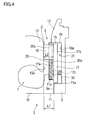
- Fig. 4 is a figure corresponding to Fig. 2 for the first embodiment.
- the components which is not shown in Fig. 4 is the same as the first embodiment, thus descriptions thereof will be omitted.
- the storage chamber 21 is formed.
- the diffuser plate 20 is arranged so that the bearing housing side surface 20a is located closer to the second diffuser wall portion 13 than the fastening surface 11a.
- the diffuser plate 20 is provided with a support member 30 extending in the direction of the axis Ax from the bearing housing side surface 20a.
- the base portion 17 of the movable vane 15 is provided with a penetrating hole 17c penetrating in the direction of the axis Ax.
- the support member 30 is inserted in the penetrating hole 17c.
- the size of the base portion 17 is set so that the facing surface 17a of the movable vane 15 in the projected position contacts the fastening surface 11a.
- the position of the movable vane 15 in the projected position is decided by the fastening surface 11a of the compressor housing 10.
- a part which covers the concave portion 19 in the fastening surface 11a corresponds to a positioning surface of the present invention.
- the projecting length L2 of the vane portions 18 is also set as a value which is slightly smaller than the distance L1 between the wall surface 13a of the second diffuser wall portion 13 and the fastening surface 11a.
- the position of the movable vane 15 in the projected position is decided by the fastening surface 11a.
- the size of the clearance C between the movable vane 15 in the projected position and the second diffuser wall portion 13 is decided by the difference between the distance L1 between the wall surface 13a of the second diffuser wall portion 13 and the fastening surface 11a and the projecting length L2 of the vane portions 18. Accordingly, it is possible to decrease the portions to be managed about the size for decreasing the clearance C to two portions. Thereby, it is possible to suppress varying the size of the clearance C for each product. It is possible to manage the sizes of the portions which can influence the size of the clearance C easily.
- the projecting length L2 of the vane portions 18 is slightly smaller than the distance L1, it is possible to prevent the vane portions 18 from deforming.
- the position of the movable vane 15 is decided directly by the fastening surface 11a, it is possible to increase the positioning accuracy for the movable vane 15 in the projected position. Thereby, since it is possible to manage the size of the clearance C further accurately, it is possible to decrease the size of the clearance C further.
- the present invention is not limited to the above-described embodiments, and may be executed in various modes.
- the centrifugal compressor of the present invention may be used alone without being incorporated into the turbo supercharger.
Landscapes
- Engineering & Computer Science (AREA)
- Mechanical Engineering (AREA)
- General Engineering & Computer Science (AREA)
- Chemical & Material Sciences (AREA)
- Combustion & Propulsion (AREA)
- Physics & Mathematics (AREA)
- Geometry (AREA)
- Structures Of Non-Positive Displacement Pumps (AREA)
- Supercharger (AREA)
Abstract
Description
- The present invention relates to a centrifugal compressor provided with a movable vane moving in and out of a diffuser passage, and a turbo supercharger having the centrifugal compressor.
- There is a known centrifugal compressor in which a vane movable between a position where it is projected into a diffuser passage and a position where it is housed in a housing chamber provided in a diffuser wall is provided in a diffuser portion (see Patent Literature 1).
- Patent Literature 1:
JP-A-2001-329996 - In the centrifugal compressor of the Patent Literature 1, the vane collides against an opposed side diffuser wall when the vane moves to reach the projected position. Thereby, there is a possibility that the vane is deformed in this moment and a part of the opposed side diffuser wall which has collided against the vane wears away. In order to prevent this problem, it is necessary that a clearance is formed between the opposed side diffuser wall and the vane when the vane reaches the projected position. However, when the clearance is large, a supercharging efficiency is decreased. Thus, it is necessary to decrease the clearance. The size of the clearance is decided by a length of the vane projecting in the diffuser at the projected position and a distance between the diffuser walls. Thereby, by managing sizes of portions to influence the clearance in the vane and the housing, it is possible to decrease the clearance. However, when the number of the portions the size of which are managed is large, it is laborious to manage the sizes thereof and production cost is increased.
- In view of the foregoing, an object of the present invention is to provide a centrifugal compressor and a turbo supercharger, which can decrease the number of portions to be the sizes of which are managed for decreasing a size of a clearance between a vane existing at a projected position and a diffuser wall.
- A centrifugal compressor of the present invention comprises: a housing assembly that includes a first housing which supports a rotating shaft so as to be rotatable about an axis, the rotating shaft having an impeller on an end portion of itself, and a second housing which houses the impeller inside and is assembled with the first housing so as to be aligned in the direction of the axis with the first housing, wherein a diffuser serving as a passage space communicated with an exit side of the impeller is formed by a first diffuser wall portion of a first housing side and a second diffuser wall portion of a second housing side on outer periphery of the impeller, and a movable vane that includes a base portion which is arranged in a storage chamber provided in the first diffuser wall portion and has a facing surface opposing to the second diffuser wall portion, and vane portions which project from the facing surface to a second diffuser wall portion side, wherein the movable vane is movable in the direction of the axis between a projected position where the facing surface contacts with a positioning surface provided in the storage chamber and the vane portions project in the diffuser and a retracted position where the vane portions are retracted to a first diffuser wall portion side further than the projected position, wherein the first housing is provided with a mounting surface located in a direction perpendicular to the direction of the axis, the second housing includes an affixing portion projecting to the first housing side further than the second diffuser wall portion, and a fastening surface being provided to the affixing portion and located in a direction perpendicular to the direction of the axis, wherein the second housing is assembled with the first housing by attaching the fastening surface to the mounting surface, and the positioning surface is provided in the storage chamber so as to be flush with the fastening surface.
- In the centrifugal compressor of the present invention, the positioning surface is flush with the fastening surface. Thereby, the size of a clearance between the movable vane in the projected position and the second diffuser wall portion is decided by two sizes which are the size of a distance in the direction of the axis between the fastening surface and the second diffuser wall portion and the size of a projecting length of the vane portion in the direction of the axis from the base portion. Thereby, according to the centrifugal compressor of the present invention, it is possible to decrease the number of portions to be managed about the size for decreasing the size of the clearance to two. By decreasing the number of the portions to be managed about the size to two in this manner, it is possible to suppress an influence which is given to the size of the clearance by a machining error of each portions and an assembly error. Thereby, it is possible to suppress varying the size of the clearance for each product. Further, by decreasing the number of the portions to be managed about the size, it is possible to easily manage the sizes of these portions. According to the centrifugal compressor of the present invention, since it is possible to manage the size of the clearance accurately, it is possible to decrease the size of the clearance while forming the clearance between the movable vane in the projected position and the second diffuser wall portion.
- In one embodiment of the centrifugal compressor of the present invention, wherein the first diffuser wall portion may be provided with a concave portion hollowing in the direction of the axis further than the mounting surface and housing the base portion so as to be movable in the direction of the axis to become the storage chamber, the fastening surface may be attached to the mounting surface so that a part of the fastening surface covers at least a part of the concave portion, and the positioning surface may be the part of the fastening surface covering the concave portion. In this case, since the position of the movable vane in the projected position is decided directly by the fastening surface, it is possible to increase the positioning accuracy for the movable vane in the projected position. Thereby, it is possible to decrease the size of the clearance further while forming the clearance between the movable vane in the projected position and the second diffuser wall portion.
- A turbo supercharger of the present invention comprises the centrifugal compressor mentioned above and a turbine, wherein the centrifugal compressor is provided to an intake passage of an internal combustion engine and the turbine is provided to an exhaust passage of the internal combustion engine, the turbine recovers exhaust energy of the internal combustion engine, and the turbo supercharger supercharges the internal combustion engine by driving to rotate the impeller of the centrifugal compressor by recovered exhaust energy.
- According to the turbo supercharger of the present invention, since the turbo supercharger has the above mentioned centrifugal compressor, it is possible to decrease the number of the portions to be managed about the size for decreasing the size of the clearance between the movable vane in the projected position and the second diffuser wall portion to two. Thereby, it is possible to decrease the size of the clearance while forming the clearance between the movable vane in the projected position and the second diffuser wall portion. Accordingly, it is possible to suppress decreasing a supercharging efficiency when the movable vane reaches the projected position.
-
-
Fig. 1 is a view of a main part of a turbo supercharger in which a centrifugal compressor according to a first embodiment of the present invention is incorporated. -
Fig. 2 is an enlarged view of a part around a diffuser. -
Fig. 3 is an enlarged view of a movable vane. -
Fig. 4 is an enlarged view of a part around a diffuser of a centrifugal compressor according to a second embodiment of the present invention. -
Fig. 1 shows a main part of a turbo supercharger in which a centrifugal compressor according to a first embodiment of the present invention is incorporated. The turbo supercharger 1 is attached to an internal combustion engine that is mounted on a vehicle as a traveling power source. The turbo supercharger 1 includes acentrifugal compressor 2 and a turbine (not shown) . The turbine is similar to a turbine of a well known turbo supercharger. Thereby, illustration and description thereof will be omitted. - The
compressor 2 has ahousing assembly 3 and animpeller 4 housed in thehousing assembly 3. Thehousing assembly 3 has awheel chamber 5 in which theimpeller 4 is housed, adiffuser 6 provided outward in a radial direction of thewheel chamber 4 as a passage space communicated with the exit side of theimpeller 4, and a scrolledscroll chamber 7 provided outward in a radial direction of thediffuser 6 and communicated with thediffuser 6. Theimpeller 4 is fixed to an end portion of a rotating shaft 8 by anut 8a, and rotates with the rotating shaft 8. A turbine wheel of the turbine is attached to the other end portion of the rotating shaft 8. These parts are the same as those of a well-known centrifugal compressor provided to a turbo supercharger, thus a detailed description thereof will be omitted. - The
housing assembly 3 has a bearinghousing 9 serving as a first housing and acompressor housing 10 serving as a second housing. The bearinghousing 9 supports the rotating shaft 8 so as to be rotatable about an axis Ax. Thecompressor housing 10 houses theimpeller 4 inside so as to be rotatable about the axis Ax, and is assembled with thebearing housing 9 so as to be aligned in the direction of the axis Ax with it.Fig. 2 is an enlarged view of a part around thediffuser 6. As shown in this figure, the bearinghousing 9 has amounting surface 9a located in a direction perpendicular to the direction of the axis Ax. Themounting surface 9a is arranged outward in the radial direction further than thediffuser 6. Thecompressor housing 10 is provided with an affixingportion 11 mounted to themounting surface 9a. The affixingportion 11 is provided with afastening surface 11a located in a direction perpendicular to the direction of the axis Ax as with themounting surface 9a. Thecompressor housing 10 is assembled with thebearing housing 9 so that thefastening surface 11a contacts themounting surface 9a. - As shown in this figure, the
diffuser 6 is formed by a firstdiffuser wall portion 12 which is arranged on a side of the bearinghousing 9 and a seconddiffuser wall portion 13 which is arranged on a side of thecompressor housing 10. Thesediffuser wall portions diffuser wall portion 13 has awall surface 13a forming thediffuser 6. Thewall surface 13a is arranged at a position which is concaved at a distance L1 in the direction of the axis Ax from thefastening surface 11a. The firstdiffuser wall portion 12 is provided with amovable vane mechanism 14. Themovable vane mechanism 14 has amovable vane 15 and adriving apparatus 16 which drives themovable vane 15 in the direction of the axis Ax. Thedriving apparatus 16 may be a known apparatus to drive themovable vane 15 in the direction of the axis Ax by transmitting a power of an actuator (not shown) to themovable vane 15 via a link mechanism and the like. Thereby, a detailed description thereof will be omitted. -
Fig. 3 is an enlarged view of themovable vane 15. As shown in this figure, themovable vane 15 has a hollow disk shapedbase portion 17 and a plurality ofvane portions 18 projected from thebase portion 17. In this figure, only onevane portion 18 is shown. Eachvane portion 18 projects toward the seconddiffuser wall portion 13 from thebase portion 17. Thebase portion 17 has a facingsurface 17a opposing to the seconddiffuser wall portion 13 and located in a direction perpendicular to the direction of the axis Ax. Thevane portion 18 projects in the direction of the axis Ax from the facingsurface 17a. As a projecting length L2 of thevane portions 18, set is a value which is slightly smaller than the distance L1 between thewall surface 13a of the seconddiffuser wall portion 13 and thefastening surface 11a. - The bearing
housing 9 is provided with aconcave portion 19 arranging inward in the radial direction of the mountingsurface 9a and hollowing in the direction of the axis Ax from the mountingsurface 9a. Theconcave portion 19 is formed around the entire outer periphery of theimpeller 4. Adiffuser plate 20 is mounted on the bearinghousing 9 so as to cover theconcave portion 19. As shown in this figure, thediffuser plate 20 is attached in astep portion 11b provided to the affixingportion 11 of thecompressor housing 10. Thediffuser plate 20 is fixed, as being sandwiched between the bearinghousing 9 and thecompressor housing 10. Thestep portion 11b is formed so as to be arranged at a position where a bearinghousing side surface 20a of thediffuser plate 20 is flush with thefastening surface 11a in a case that thediffuser plate 20 is attached. Thereby, thediffuser plate 20 is mounted on the bearinghousing 9 so that the bearinghousing side surface 20a contacts with the mountingsurface 9a. By covering theconcave portion 19 by thediffuser plate 20 in this manner, astorage chamber 21 is formed in the firstdiffuser wall portion 12. Thediffuser plate 20 becomes a part of the firstdiffuser wall portion 12 and forms one side of wall surface of thediffuser 6. Themovable vane 15 is arranged in thestorage chamber 21 so as to be movable in the direction of the axis Ax. Thediffuser plate 20 is provided with penetratingholes 20b having a same shape as a cross sectional shape of thevane portion 18, and the penetratingholes 20b being equal in number to thevane portions 18. Themovable vane 15 is arranged in thestorage chamber 21 so that each of thevane portions 18 is inserted in the penetratinghole 20b. - Next, motion of the
movable vane 15 will be described. As described above, the drivingapparatus 16 drives themovable vane 15 in the direction of the axis Ax. At this moment, the drivingapparatus 16 drives themovable vane 15 in the direction of the axis Ax between a projected position where thevane portions 18 are projected into thediffuser 6 and a retracted position where thevane portions 18 are retracted in the firstdiffuser wall portion 12. As shown inFig. 2 , at the projected position, the facingsurface 17a of themovable vane 15 contacts with the bearinghousing side surface 20a of thediffuser plate 20. Thereby, the position of themovable vane 15 in the projected position is decided. Accordingly, the bearinghousing side surface 20a of thediffuser plate 20 corresponds to a positioning surface of the present invention. As described above, the projecting length L2 of thevane portions 18 is slightly smaller than the distance L1 between thewall surface 13a of the seconddiffuser wall portion 13 and thefastening surface 11a. Thereby, it is possible to prevent a collision between thevane portion 18 and thewall surface 13a in the projected position. On the other hand, at the retracted position, by contacting asurface 17b on the side opposite to the facingsurface 17a of thebase portion 17 with a bottom 19a of theconcave portion 19, the position of themovable vane 15 is decided. - As described above, in the
compressor 2 of the present invention, the bearinghousing side surface 20a of thediffuser plate 20 deciding the position of themovable vane 15 in the projected position is flush with thefastening surface 11a. Thereby, as shown inFig. 2 , the size of a clearance C between themovable vane 15 and the seconddiffuser wall portion 13 in the projected position is decided by a difference between the distance L1 in the direction of the axis Ax between thewall surface 13a of the seconddiffuser wall portion 13 and thefastening surface 11a and the projecting length L2 of thevane portions 18. That is, it is possible to manage the size of the clearance C by managing two sizes which are the size of the distance L1 and the size of the projecting length L2. By decreasing portions to be managed about the size to two portions, it is possible to suppress an influence which is given to the size of the clearance C by a machining error of each portions and an assembly error. Thereby, it is possible to suppress varying the size of the clearance C for each product. By decreasing the number of portions to be managed about the size, it is possible to easily manage the sizes of these portions. In thecompressor 2, by making the projecting length L2 of thevane portion 18 slightly smaller than the distance L1, it is possible to form the clearance C. Thereby, it is possible to prevent thevane portions 18 from deforming. Since the size of the clearance C is decided by only the size of the distance L1 and the size of the projecting length L2, it is possible to manage the size of the clearance C accurately. Thereby, it is possible to decrease the size of the clearance C while forming the clearance C between themovable vane 15 in the projected position and the seconddiffuser wall portion 13. - The centrifugal compressor according to a second embodiment of the present invention will be described with reference to
Fig. 4 . In this embodiment, the same components as those in the first embodiment are denoted by the same reference numeral, and descriptions thereof will be omitted.Fig. 4 is a figure corresponding toFig. 2 for the first embodiment. The components which is not shown inFig. 4 is the same as the first embodiment, thus descriptions thereof will be omitted. - As shown in this figure, in the present embodiment, by covering the
concave portion 19 with thediffuser plate 20 and a part of thefastening surface 11a of thecompressor housing 10, thestorage chamber 21 is formed. Thediffuser plate 20 is arranged so that the bearinghousing side surface 20a is located closer to the seconddiffuser wall portion 13 than thefastening surface 11a. For fixing thediffuser plate 20 in such position, thediffuser plate 20 is provided with asupport member 30 extending in the direction of the axis Ax from the bearinghousing side surface 20a. Thebase portion 17 of themovable vane 15 is provided with a penetratinghole 17c penetrating in the direction of the axis Ax. Thesupport member 30 is inserted in the penetratinghole 17c. As shown in this figure, in the present embodiment, the size of thebase portion 17 is set so that the facingsurface 17a of themovable vane 15 in the projected position contacts thefastening surface 11a. Namely, in the present embodiment, the position of themovable vane 15 in the projected position is decided by thefastening surface 11a of thecompressor housing 10. Thereby, a part which covers theconcave portion 19 in thefastening surface 11a corresponds to a positioning surface of the present invention. In the present embodiment, the projecting length L2 of thevane portions 18 is also set as a value which is slightly smaller than the distance L1 between thewall surface 13a of the seconddiffuser wall portion 13 and thefastening surface 11a. - According to the second embodiment, the position of the
movable vane 15 in the projected position is decided by thefastening surface 11a. Thereby, similarly to the above described first embodiment, the size of the clearance C between themovable vane 15 in the projected position and the seconddiffuser wall portion 13 is decided by the difference between the distance L1 between thewall surface 13a of the seconddiffuser wall portion 13 and thefastening surface 11a and the projecting length L2 of thevane portions 18. Accordingly, it is possible to decrease the portions to be managed about the size for decreasing the clearance C to two portions. Thereby, it is possible to suppress varying the size of the clearance C for each product. It is possible to manage the sizes of the portions which can influence the size of the clearance C easily. In the second embodiment, since the projecting length L2 of thevane portions 18 is slightly smaller than the distance L1, it is possible to prevent thevane portions 18 from deforming. In this embodiment, since the position of themovable vane 15 is decided directly by thefastening surface 11a, it is possible to increase the positioning accuracy for themovable vane 15 in the projected position. Thereby, since it is possible to manage the size of the clearance C further accurately, it is possible to decrease the size of the clearance C further. - The present invention is not limited to the above-described embodiments, and may be executed in various modes. For example, the centrifugal compressor of the present invention may be used alone without being incorporated into the turbo supercharger.
Claims (3)
- A centrifugal compressor comprising:a housing assembly that includes a first housing which supports a rotating shaft so as to be rotatable about an axis, the rotating shaft having an impeller on an end portion of itself, and a second housing which houses the impeller inside and is assembled with the first housing so as to be aligned in the direction of the axis with the first housing, wherein a diffuser serving as a passage space communicated with an exit side of the impeller is formed by a first diffuser wall portion of a first housing side and a second diffuser wall portion of a second housing side on outer periphery of the impeller, anda movable vane that includes a base portion which is arranged in a storage chamber provided in the first diffuser wall portion and has a facing surface opposing to the second diffuser wall portion, and vane portions which project from the facing surface to a second diffuser wall portion side, whereinthe movable vane is movable in the direction of the axis betweena projected position where the facing surface contacts with a positioning surface provided in the storage chamber and the vane portions project in the diffuser anda retracted position where the vane portions are retracted to a first diffuser wall portion side further than the projected position, whereinthe first housing is provided with a mounting surface located in a direction perpendicular to the direction of the axis,the second housing includes an affixing portion projecting to the first housing side further than the second diffuser wall portion, and a fastening surface being provided to the affixing portion and located in a direction perpendicular to the direction of the axis, wherein the second housing is assembled with the first housing by attaching the fastening surface to the mounting surface, andthe positioning surface is provided in the storage chamber so as to be flush with the fastening surface.
- The centrifugal compressor according to claim 1, wherein
the first diffuser wall portion is provided with a concave portion hollowing in the direction of the axis further than the mounting surface and housing the base portion so as to be movable in the direction of the axis to become the storage chamber,
the fastening surface is attached to the mounting surface so that a part of the fastening surface covers at least a part of the concave portion, and
the positioning surface is the part of the fastening surface covering the concave portion. - A turbo supercharger comprising
the centrifugal compressor according to claim 1 or 2 and a turbine, wherein
the centrifugal compressor is provided to an intake passage of an internal combustion engine and the turbine is provided to an exhaust passage of the internal combustion engine,
the turbine recovers exhaust energy of the internal combustion engine, and the turbo supercharger supercharges the internal combustion engine by driving to rotate the impeller of the centrifugal compressor by recovered exhaust energy.
Applications Claiming Priority (1)
| Application Number | Priority Date | Filing Date | Title |
|---|---|---|---|
| PCT/JP2010/054673 WO2011114487A1 (en) | 2010-03-18 | 2010-03-18 | Centrifugal compressor and turbo supercharger |
Publications (2)
| Publication Number | Publication Date |
|---|---|
| EP2549122A1 true EP2549122A1 (en) | 2013-01-23 |
| EP2549122A4 EP2549122A4 (en) | 2013-12-18 |
Family
ID=44648616
Family Applications (1)
| Application Number | Title | Priority Date | Filing Date |
|---|---|---|---|
| EP10847901.5A Withdrawn EP2549122A4 (en) | 2010-03-18 | 2010-03-18 | CENTRIFUGAL COMPRESSOR AND TURBO SUPER LOADER |
Country Status (5)
| Country | Link |
|---|---|
| US (1) | US8863513B2 (en) |
| EP (1) | EP2549122A4 (en) |
| JP (1) | JP5344082B2 (en) |
| CN (1) | CN102472298A (en) |
| WO (1) | WO2011114487A1 (en) |
Families Citing this family (10)
| Publication number | Priority date | Publication date | Assignee | Title |
|---|---|---|---|---|
| US8820072B2 (en) * | 2011-08-23 | 2014-09-02 | Honeywell International Inc. | Compressor diffuser plate |
| DE102012212410A1 (en) * | 2012-07-16 | 2014-01-30 | Siemens Aktiengesellschaft | Parallel diffuser for a fluid machine |
| KR102027187B1 (en) * | 2012-07-27 | 2019-10-01 | 보르그워너 인코퍼레이티드 | Retractable vane diffuser for compressors |
| CN103148021B (en) * | 2013-03-22 | 2016-06-08 | 清华大学 | There is centrifugal compressor and the turbocharger of entry guide vane |
| CN104421209B (en) * | 2013-08-26 | 2017-02-08 | 珠海格力电器股份有限公司 | regulator structure and centrifugal compressor |
| JP6256142B2 (en) * | 2014-03-26 | 2018-01-10 | 株式会社豊田自動織機 | Centrifugal compressor |
| CN106715838B (en) * | 2014-08-28 | 2018-12-04 | 三菱重工发动机和增压器株式会社 | expansion turbine and turbocharger |
| WO2018179100A1 (en) * | 2017-03-28 | 2018-10-04 | 三菱重工エンジン&ターボチャージャ株式会社 | Centrifugal compressor and turbocharger |
| DE102018107264A1 (en) * | 2018-03-27 | 2019-10-02 | Man Energy Solutions Se | Centrifugal compressor and turbocharger |
| CN117553010B (en) * | 2022-08-05 | 2024-11-08 | 盖瑞特动力科技(上海)有限公司 | Turbocharger with vaned diffuser for compressor |
Family Cites Families (21)
| Publication number | Priority date | Publication date | Assignee | Title |
|---|---|---|---|---|
| BE793550A (en) * | 1971-12-29 | 1973-04-16 | Gen Electric | CENTRIFUGAL PUMP WITH ADJUSTABLE DIFFUSER |
| US4219305A (en) * | 1978-12-26 | 1980-08-26 | Carrier Corporation | Diffuser control |
| CH638867A5 (en) * | 1979-03-16 | 1983-10-14 | Bbc Brown Boveri & Cie | TURBOCHARGER WITH A DEVICE FOR CONTROLLING THE SWALLOWING CAPACITY OF THE TURBINE. |
| US4416583A (en) * | 1980-04-04 | 1983-11-22 | Carrier Corporation | Centrifugal vapor compressor |
| US4378194A (en) * | 1980-10-02 | 1983-03-29 | Carrier Corporation | Centrifugal compressor |
| US4460310A (en) * | 1982-06-28 | 1984-07-17 | Carrier Corporation | Diffuser throttle ring control |
| GB8318489D0 (en) * | 1983-07-08 | 1983-08-10 | Holset Engineering Co | Variable inlet area turbine |
| US4844690A (en) * | 1985-01-24 | 1989-07-04 | Carrier Corporation | Diffuser vane seal for a centrifugal compressor |
| JPS62135899U (en) * | 1986-02-20 | 1987-08-26 | ||
| GB2234295B (en) * | 1989-07-21 | 1993-07-21 | Rolls Royce Plc | Gas turbine engine compressor assembly |
| US5452986A (en) * | 1994-01-12 | 1995-09-26 | Dresser-Rand Company | Vaned diffuser |
| JP4573074B2 (en) * | 2000-05-24 | 2010-11-04 | 株式会社Ihi | Centrifugal compressor with variable diffuser and its control method |
| US6652224B2 (en) * | 2002-04-08 | 2003-11-25 | Holset Engineering Company Ltd. | Variable geometry turbine |
| US7207176B2 (en) * | 2002-11-19 | 2007-04-24 | Cummins Inc. | Method of controlling the exhaust gas temperature for after-treatment systems on a diesel engine using a variable geometry turbine |
| GB0228237D0 (en) * | 2002-12-04 | 2003-01-08 | Holset Engineering Co | Variable geometry turbine |
| JP4389442B2 (en) * | 2002-12-17 | 2009-12-24 | 株式会社Ihi | Centrifugal compressor |
| JP2004194612A (en) | 2002-12-20 | 2004-07-15 | Ezaki Glico Co Ltd | Mitochondrial dna 16s ribosome rna gene base sequence of cockroach and method for identifying species of cockroach |
| JP4466080B2 (en) * | 2004-01-07 | 2010-05-26 | 株式会社Ihi | Centrifugal compressor |
| JP2009270472A (en) * | 2008-05-07 | 2009-11-19 | Toyota Motor Corp | Centrifugal supercharger |
| CN102597532B (en) * | 2009-11-17 | 2014-09-17 | 丰田自动车株式会社 | Centrifugal compressor and turbo supercharger |
| WO2012077231A1 (en) * | 2010-12-10 | 2012-06-14 | トヨタ自動車株式会社 | Centrifugal compressor |
-
2010
- 2010-03-18 CN CN2010800287020A patent/CN102472298A/en active Pending
- 2010-03-18 EP EP10847901.5A patent/EP2549122A4/en not_active Withdrawn
- 2010-03-18 JP JP2012505392A patent/JP5344082B2/en not_active Expired - Fee Related
- 2010-03-18 US US13/381,296 patent/US8863513B2/en not_active Expired - Fee Related
- 2010-03-18 WO PCT/JP2010/054673 patent/WO2011114487A1/en not_active Ceased
Also Published As
| Publication number | Publication date |
|---|---|
| CN102472298A (en) | 2012-05-23 |
| EP2549122A4 (en) | 2013-12-18 |
| WO2011114487A1 (en) | 2011-09-22 |
| JPWO2011114487A1 (en) | 2013-06-27 |
| JP5344082B2 (en) | 2013-11-20 |
| US20120111002A1 (en) | 2012-05-10 |
| US8863513B2 (en) | 2014-10-21 |
Similar Documents
| Publication | Publication Date | Title |
|---|---|---|
| EP2549122A1 (en) | Centrifugal compressor and turbo supercharger | |
| EP3144497A1 (en) | Electric supercharger | |
| US20170114714A1 (en) | Compressor housing for a turbocharger and method for manufacturing the same | |
| CN108699961B (en) | Pressure booster | |
| EP1867840A2 (en) | Variable nozzle device | |
| US20150292350A1 (en) | Exhaust-gas turbocharger | |
| EP3109474A1 (en) | Electric scroll compressor | |
| US10465550B2 (en) | Variable geometry turbocharger | |
| EP1910687B1 (en) | Variable geometry compressor housing and manufacturing method thereof | |
| US11635092B2 (en) | Rotating device | |
| US9903379B2 (en) | Variable nozzle unit and variable geometry system turbocharger | |
| CN109477419B (en) | Variable capacity supercharger | |
| JP2010229908A (en) | Variable nozzle mechanism and variable displacement turbocharger | |
| US10844902B2 (en) | Turbocharger | |
| JP2012241560A (en) | Compressor housing for supercharger | |
| EP3406904B1 (en) | Centrifugal compression test device | |
| US9732767B2 (en) | Compressor cover with integrated heat shield for an actuator | |
| WO2017141897A1 (en) | Nozzle driving mechanism, supercharger, variable capacity supercharger | |
| EP2546527B1 (en) | Diffuser device, centrifugal compressor, and turbo supercharger | |
| CN105899780A (en) | Exhaust-gas turbocharger | |
| JPWO2020012731A1 (en) | Supercharger | |
| US10883513B2 (en) | Impeller, rotary machine, and turbocharger | |
| JP5811593B2 (en) | Guide vane unit bearing structure and turbocharger | |
| JP2010255483A (en) | Turbocharger | |
| US11739655B2 (en) | Variable nozzle device and variable-displacement type exhaust turbocharger |
Legal Events
| Date | Code | Title | Description |
|---|---|---|---|
| PUAI | Public reference made under article 153(3) epc to a published international application that has entered the european phase |
Free format text: ORIGINAL CODE: 0009012 |
|
| 17P | Request for examination filed |
Effective date: 20111222 |
|
| AK | Designated contracting states |
Kind code of ref document: A1 Designated state(s): AT BE BG CH CY CZ DE DK EE ES FI FR GB GR HR HU IE IS IT LI LT LU LV MC MK MT NL NO PL PT RO SE SI SK SM TR |
|
| RAP1 | Party data changed (applicant data changed or rights of an application transferred) |
Owner name: TOYOTA JIDOSHA KABUSHIKI KAISHA |
|
| DAX | Request for extension of the european patent (deleted) | ||
| A4 | Supplementary search report drawn up and despatched |
Effective date: 20131115 |
|
| RIC1 | Information provided on ipc code assigned before grant |
Ipc: F04D 29/44 20060101ALI20131108BHEP Ipc: F04D 29/62 20060101AFI20131108BHEP Ipc: F04D 29/46 20060101ALI20131108BHEP |
|
| GRAP | Despatch of communication of intention to grant a patent |
Free format text: ORIGINAL CODE: EPIDOSNIGR1 |
|
| RIC1 | Information provided on ipc code assigned before grant |
Ipc: F04D 29/46 20060101ALI20150224BHEP Ipc: F04D 29/44 20060101AFI20150224BHEP Ipc: F04D 27/02 20060101ALI20150224BHEP |
|
| INTG | Intention to grant announced |
Effective date: 20150401 |
|
| RIN1 | Information on inventor provided before grant (corrected) |
Inventor name: TABATA, MASAKAZU |
|
| STAA | Information on the status of an ep patent application or granted ep patent |
Free format text: STATUS: THE APPLICATION IS DEEMED TO BE WITHDRAWN |
|
| 18D | Application deemed to be withdrawn |
Effective date: 20150812 |