EP2549054B1 - Connecting sleeve for extension ladder - Google Patents
Connecting sleeve for extension ladder Download PDFInfo
- Publication number
- EP2549054B1 EP2549054B1 EP10847652.4A EP10847652A EP2549054B1 EP 2549054 B1 EP2549054 B1 EP 2549054B1 EP 10847652 A EP10847652 A EP 10847652A EP 2549054 B1 EP2549054 B1 EP 2549054B1
- Authority
- EP
- European Patent Office
- Prior art keywords
- seat
- rotating plate
- shafts
- connecting sleeve
- connecting block
- Prior art date
- Legal status (The legal status is an assumption and is not a legal conclusion. Google has not performed a legal analysis and makes no representation as to the accuracy of the status listed.)
- Not-in-force
Links
- 238000010586 diagram Methods 0.000 description 2
- 238000010276 construction Methods 0.000 description 1
- 238000005034 decoration Methods 0.000 description 1
Images


Classifications
-
- E—FIXED CONSTRUCTIONS
- E06—DOORS, WINDOWS, SHUTTERS, OR ROLLER BLINDS IN GENERAL; LADDERS
- E06C—LADDERS
- E06C7/00—Component parts, supporting parts, or accessories
- E06C7/08—Special construction of longitudinal members, or rungs or other treads
- E06C7/082—Connections between rungs or treads and longitudinal members
- E06C7/086—Connections between rungs or treads and longitudinal members with a connecting piece inserted in a hollow rung
-
- E—FIXED CONSTRUCTIONS
- E06—DOORS, WINDOWS, SHUTTERS, OR ROLLER BLINDS IN GENERAL; LADDERS
- E06C—LADDERS
- E06C1/00—Ladders in general
- E06C1/02—Ladders in general with rigid longitudinal member or members
- E06C1/04—Ladders for resting against objects, e.g. walls poles, trees
- E06C1/08—Ladders for resting against objects, e.g. walls poles, trees multi-part
- E06C1/12—Ladders for resting against objects, e.g. walls poles, trees multi-part extensible, e.g. telescopic
- E06C1/125—Ladders for resting against objects, e.g. walls poles, trees multi-part extensible, e.g. telescopic with tubular longitudinal members nested within each other
-
- E—FIXED CONSTRUCTIONS
- E06—DOORS, WINDOWS, SHUTTERS, OR ROLLER BLINDS IN GENERAL; LADDERS
- E06C—LADDERS
- E06C7/00—Component parts, supporting parts, or accessories
- E06C7/06—Securing devices or hooks for parts of extensible ladders
Definitions
- the present invention relates to the field of an extending ladder, in particular to a connecting sleeve for an extending ladder.
- Ladders are now widely used in the fields of construction, decoration, advertisement and family residence.
- an extending ladder which can extend and shorten is comparatively popular.
- the ladder is not in use, due to the fact that it can be shortened, it is easy for storage and transportation.
- a Chinese patent CN2716479Y with the title of An Extending Ladder discloses such an extending ladder which comprises: stiles and rungs, each stile is formed of telescopically collapsible columns which are disposed in a nested arrangement; the multiple rungs are fixed between two opposite stiles, each end of each rung is separately provided with an extensible pin which matches with a corresponding positioning socket formed on the column; the upper end of each column is arranged with a circular connecting sleeve which is connected with the rung.
- the technical problem which the present invention seeks to solve is to provide, in response to the current state of the prior art, a connecting sleeve for an extending ladder, which provides a fixed space between the upper and lower rungs, thereby effectively preventing the fingers from being pressed by the rungs when folding the extending ladder. Additionally, the whole height of the extending ladder will not exceed the desired level when the product is packaged and transported, thereby being extremely fit for actual use.
- the connecting sleeve for an extending ladder comprises a connecting ring and a connecting block formed unitarily with each other and is characterized in that a seat and a rotating plate are mounted on the surface of the joint between the connecting ring and the connecting block;
- the seat is fixed relative to the connecting ring, a socket is provided in the center of the seat, and two shafts are formed at two sides of the socket, respectively extending to the center;
- the rotating plate is substantially in a T-shape, a vertical portion thereof being inserted into the socket of the seat while a transverse portion thereof is located on the seat, additionally, two shafts of the seat are inserted transversely into a through hole provided on the vertical portion;
- a torsion spring is mounted in the through hole of the vertical portion of the rotating plate and outside the shafts, a first end of the torsion spring is connected to the inner wall of the through hole of the rotating plate, and a second end of the torsion spring is
- the connecting sleeve is connected with the corresponding stile by surrounding the column of the corresponding stile, while the connecting block is connected with the rung by inserting the end of the connecting block into the rung.
- the height of the rotating plate should be bigger than the thickness of the fingers.
- the seat can be composed of left and right sub-seats joined with each other, and the bottom of each sub-seat is inserted via a projecting column into the surface of the joint between the connecting ring and the connecting block.
- the transverse portion of the rotating plate may be trapeziform, so that the top thereof has a horizontal surface for convenient propping against the bottom of the upper rung.
- the thickness of the rotating plate is adapted to that of the seat, so that the rotating plate can form a whole with the seat when the rotating plate stands up, the surface can be tidy, and after the transverse portion of the rotating plate is folded down to be at the side of the seat, the surface of the rotating plate is substantially at the same level as the top surface of the seat.
- the whole height of the rotating plate is preferably bigger than or equal to 2cm.
- the advantages of this invention are: with the seat, the rotating plate and the torsion spring therebetween, the transverse portion of the rotating plate is allowed to rotate round the shafts relative to the seat and the connecting sleeve itself, then, when the extending ladder is in normal use, as the rotating plate can always keep standing up relative to the seat, the rotating plate forms a fixed space between the upper and lower rungs. This space may accommodate the fingers, thereby effectively preventing the fingers on the lower rung from being pressed by the upper rung when the extending ladder is folded.
- the transverse portion of the rotating plate can be folded down to be located at the side of the seat; accordingly, the distance between the upper and lower rungs is only the height of the seat, so the whole height thereof will not exceed the desired level when the product is packaged and transported, thereby being extremely fit for actual use.
- the extending ladder which includes the embodiment of the present invention, comprises two stiles disposed opposite each other and a plurality of rungs each fixed between the two stiles; each stile comprises two inner and outer telescopically collapsible columns which are disposed in a nested arrangement; each rung is fixed between two opposite columns in the same section, furthermore, two ends of each rung are fixed with corresponding columns of the stiles via the connecting sleeve of the embodiment of the present invention.
- the connecting sleeve for an extending ladder comprises a connecting ring 1 and a connecting block 2 formed unitarily with each other; a seat 3 and a rotating plate 4 are mounted on the surface of the joint between the connecting ring 1 and the connecting block 2.
- the connecting sleeve 1 is fixed with the corresponding stile by surrounding the column of the corresponding stile, while the connecting block 2 is inserted into the end of the corresponding rung.
- the seat 3 is composed of left and right sub-seats 3a joined with each other, each sub-seat 3a is fixed relative to the connecting ring 1 by inserting a projecting column 33 formed on the bottom of the sub-seat 3a at one side of the connecting ring 1.
- a socket 31 is provided in the center of the seat 3, and two shafts 32 are formed at two sides of the socket 31 respectively extending to the center of the seat 3.
- the rotating plate 4 is substantially in a T-shape, the total height of which is 3cm; a vertical portion 41 thereof is inserted into the socket 31 of the seat 3 while the transverse portion 42 thereof is trapezoidal and located on the seat 3.
- the thickness of the rotating plate 4 is basically equal to that of the seat 3.
- Two shafts 32 of the seat 3 are inserted transversely into a through hole 41a provided on the vertical portion 41, so as to allow the transverse portion 42 of the rotating plate 4 to rotate toward the connecting block 2 round the shafts 32, that is to be folded down relative to the connecting block 2.
- a torsion spring 5 is mounted in the through hole 41a of the vertical portion 41 of the rotating plate 4, and outside the shafts 32, a first end of the torsion spring 5 is connected to the inner wall of the through hole 41a of the rotating plate 4, and a second end of the torsion spring 5 is connected to the seat 3, so as to allow the transverse portion 42 of the rotating plate 4 to rotate toward the connecting block 2 round the shafts 32 and always tend to stand up on the seat 3. In other words, under no external force, the transverse portion 42 of the rotating plate 4 will always face up. Therefore, during the practical application, the upper rung of the extending ladder is separated from the lower rung by the whole rotating plate 4 and the seat 3. Only when an external force is applied on the transverse portion 42 of the rotating plate 4 can it be folded down to the connecting block 2, so that the upper rung is separated from the lower rung by the seat 3 only.
Landscapes
- Engineering & Computer Science (AREA)
- Mechanical Engineering (AREA)
- Ladders (AREA)
Description
- The present invention relates to the field of an extending ladder, in particular to a connecting sleeve for an extending ladder.
- Ladders are now widely used in the fields of construction, decoration, advertisement and family residence. In the present market, an extending ladder which can extend and shorten is comparatively popular. When the ladder is not in use, due to the fact that it can be shortened, it is easy for storage and transportation. For example, a Chinese patent
CN2716479Y with the title of An Extending Ladder (patent number: ZL200420091638.2) discloses such an extending ladder which comprises: stiles and rungs, each stile is formed of telescopically collapsible columns which are disposed in a nested arrangement; the multiple rungs are fixed between two opposite stiles, each end of each rung is separately provided with an extensible pin which matches with a corresponding positioning socket formed on the column; the upper end of each column is arranged with a circular connecting sleeve which is connected with the rung. When using such an extending ladder, because there is no fixed space between the upper and lower rungs, and the hands of users generally just rest on a certain rung, at the time of folding the extending ladder, then, hidden danger in insecurity exists because the fingers of users placed on the lower rung will be pressed by the upper rung. - The technical problem which the present invention seeks to solve is to provide, in response to the current state of the prior art, a connecting sleeve for an extending ladder, which provides a fixed space between the upper and lower rungs, thereby effectively preventing the fingers from being pressed by the rungs when folding the extending ladder. Additionally, the whole height of the extending ladder will not exceed the desired level when the product is packaged and transported, thereby being extremely fit for actual use.
- The technical solution used in the present invention for solving the above technical problem is as follows: the connecting sleeve for an extending ladder comprises a connecting ring and a connecting block formed unitarily with each other and is characterized in that a seat and a rotating plate are mounted on the surface of the joint between the connecting ring and the connecting block;
the seat is fixed relative to the connecting ring, a socket is provided in the center of the seat, and two shafts are formed at two sides of the socket, respectively extending to the center;
the rotating plate is substantially in a T-shape, a vertical portion thereof being inserted into the socket of the seat while a transverse portion thereof is located on the seat, additionally, two shafts of the seat are inserted transversely into a through hole provided on the vertical portion;
furthermore, a torsion spring is mounted in the through hole of the vertical portion of the rotating plate and outside the shafts, a first end of the torsion spring is connected to the inner wall of the through hole of the rotating plate, and a second end of the torsion spring is connected to the seat, so as to allow the transverse portion of the rotating plate to rotate toward the connecting block round the shafts and always tend to stand up on the seat. - The connecting sleeve is connected with the corresponding stile by surrounding the column of the corresponding stile, while the connecting block is connected with the rung by inserting the end of the connecting block into the rung.
- In order to further guarantee that the setting of the seat and the rotating plate effectively protect the hands of the users, the height of the rotating plate should be bigger than the thickness of the fingers.
- In order to have a convenient assembly of parts, the seat can be composed of left and right sub-seats joined with each other, and the bottom of each sub-seat is inserted via a projecting column into the surface of the joint between the connecting ring and the connecting block.
- As a further improvement, the transverse portion of the rotating plate may be trapeziform, so that the top thereof has a horizontal surface for convenient propping against the bottom of the upper rung. The thickness of the rotating plate is adapted to that of the seat, so that the rotating plate can form a whole with the seat when the rotating plate stands up, the surface can be tidy, and after the transverse portion of the rotating plate is folded down to be at the side of the seat, the surface of the rotating plate is substantially at the same level as the top surface of the seat.
- In order to ensure the rotating plate protects the fingers when standing up, the whole height of the rotating plate is preferably bigger than or equal to 2cm.
- Compared with prior art, the advantages of this invention are: with the seat, the rotating plate and the torsion spring therebetween, the transverse portion of the rotating plate is allowed to rotate round the shafts relative to the seat and the connecting sleeve itself, then, when the extending ladder is in normal use, as the rotating plate can always keep standing up relative to the seat, the rotating plate forms a fixed space between the upper and lower rungs. This space may accommodate the fingers, thereby effectively preventing the fingers on the lower rung from being pressed by the upper rung when the extending ladder is folded. Moreover, when the extending ladder is packaged and transported, the transverse portion of the rotating plate can be folded down to be located at the side of the seat; accordingly, the distance between the upper and lower rungs is only the height of the seat, so the whole height thereof will not exceed the desired level when the product is packaged and transported, thereby being extremely fit for actual use.
-
-
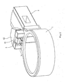
FIG. 1 is a structural schematic diagram of an embodiment of the present invention; -
FIG. 2 is a structural schematic diagram of an embodiment of the present invention when the rotating plate is rotated down; -
FIG. 3 is a three-dimensional exploded view of an embodiment of the present invention. - The present invention will be described in further detail below with reference to the embodiment in the accompanying drawings.
- The extending ladder which includes the embodiment of the present invention, comprises two stiles disposed opposite each other and a plurality of rungs each fixed between the two stiles; each stile comprises two inner and outer telescopically collapsible columns which are disposed in a nested arrangement; each rung is fixed between two opposite columns in the same section, furthermore, two ends of each rung are fixed with corresponding columns of the stiles via the connecting sleeve of the embodiment of the present invention.
- As shown in
FIG 1 to FIG 3 , the connecting sleeve for an extending ladder comprises a connectingring 1 and a connectingblock 2 formed unitarily with each other; aseat 3 and arotating plate 4 are mounted on the surface of the joint between the connectingring 1 and the connectingblock 2. - The connecting
sleeve 1 is fixed with the corresponding stile by surrounding the column of the corresponding stile, while the connectingblock 2 is inserted into the end of the corresponding rung. - The
seat 3 is composed of left andright sub-seats 3a joined with each other, eachsub-seat 3a is fixed relative to the connectingring 1 by inserting a projectingcolumn 33 formed on the bottom of thesub-seat 3a at one side of the connectingring 1. Asocket 31 is provided in the center of theseat 3, and twoshafts 32 are formed at two sides of thesocket 31 respectively extending to the center of theseat 3. - The
rotating plate 4 is substantially in a T-shape, the total height of which is 3cm; avertical portion 41 thereof is inserted into thesocket 31 of theseat 3 while thetransverse portion 42 thereof is trapezoidal and located on theseat 3. The thickness of therotating plate 4 is basically equal to that of theseat 3. - Two
shafts 32 of theseat 3 are inserted transversely into athrough hole 41a provided on thevertical portion 41, so as to allow thetransverse portion 42 of therotating plate 4 to rotate toward the connectingblock 2 round theshafts 32, that is to be folded down relative to the connectingblock 2. - Furthermore, a
torsion spring 5 is mounted in the throughhole 41a of thevertical portion 41 of therotating plate 4, and outside theshafts 32, a first end of thetorsion spring 5 is connected to the inner wall of the throughhole 41a of therotating plate 4, and a second end of thetorsion spring 5 is connected to theseat 3, so as to allow thetransverse portion 42 of therotating plate 4 to rotate toward the connectingblock 2 round theshafts 32 and always tend to stand up on theseat 3. In other words, under no external force, thetransverse portion 42 of therotating plate 4 will always face up. Therefore, during the practical application, the upper rung of the extending ladder is separated from the lower rung by the wholerotating plate 4 and theseat 3. Only when an external force is applied on thetransverse portion 42 of therotating plate 4 can it be folded down to the connectingblock 2, so that the upper rung is separated from the lower rung by theseat 3 only.
Claims (4)
- A connecting sleeve for an extending ladder comprising a connecting ring (1) and a connecting block (2) formed unitarily with each other, characterized in that a seat (3) and a rotating plate (4) are mounted on the surface of the joint between the connecting ring (1) and the connecting block (2);
the seat (3) is fixed relative to the connecting ring (1), a socket (31) is provided in the center of the seat (3), and two shafts (32) are formed at two sides of the socket (31) respectively extending to the center;
the rotating plate (4) is substantially in a T-shape, a vertical portion (41) thereof being inserted downward into the socket (31) of the seat (3) while a transverse portion (42) thereof is located on the seat (3), additionally, two shafts (32) of the seat (3) are inserted transversely into a through hole (4 1 a) provided on the vertical portion (41);
furthermore, a torsion spring (5) is mounted in the through hole (41a) of the vertical portion (41) of the rotating plate (4) and outside the shafts (32), a first end (51) of the torsion spring (5) is connected to the inner wall of the through hole (41a) of the rotating plate (4), and a second end (52) of the torsion spring (5) is connected to the seat (3), so as to allow the transverse portion (42) of the rotating plate (4) to rotate toward the connecting block (2) round the shafts and always tend to stand up on the seat (3). - The connecting sleeve for an extending ladder as claimed in claim 1, characterized in that the seat (3) is composed of left and right sub-seats (3a) joined with each other, each sub-seat (3a) is inserted into the surface of the joint between the connecting ring (1) and the connecting block (2) via a projecting column (33) formed on the bottom of the sub-seat (3a).
- The connecting sleeve for an extending ladder as claimed in claim 1 or claim 2, characterized in that the thickness of the rotating plate (4) is adapted to the thickness of the seat (3).
- The connecting sleeve for an extending ladder as claimed in claim 1 or claim 2, characterized in that the whole height of the rotating plate (4) is bigger than or equal to 2cm.
Applications Claiming Priority (2)
| Application Number | Priority Date | Filing Date | Title |
|---|---|---|---|
| CN 201010127269 CN101798902B (en) | 2010-03-17 | 2010-03-17 | A connecting sleeve for telescopic ladder |
| PCT/CN2010/000909 WO2011113183A1 (en) | 2010-03-17 | 2010-06-22 | Connecting sleeve for extension ladder |
Publications (3)
| Publication Number | Publication Date |
|---|---|
| EP2549054A1 EP2549054A1 (en) | 2013-01-23 |
| EP2549054A4 EP2549054A4 (en) | 2015-01-07 |
| EP2549054B1 true EP2549054B1 (en) | 2015-11-04 |
Family
ID=42594729
Family Applications (1)
| Application Number | Title | Priority Date | Filing Date |
|---|---|---|---|
| EP10847652.4A Not-in-force EP2549054B1 (en) | 2010-03-17 | 2010-06-22 | Connecting sleeve for extension ladder |
Country Status (3)
| Country | Link |
|---|---|
| EP (1) | EP2549054B1 (en) |
| CN (1) | CN101798902B (en) |
| WO (1) | WO2011113183A1 (en) |
Family Cites Families (11)
| Publication number | Priority date | Publication date | Assignee | Title |
|---|---|---|---|---|
| GB2203186B (en) * | 1987-03-28 | 1990-11-28 | James Brotherton | Stabilizer and tensioner |
| JP3542645B2 (en) * | 1994-09-20 | 2004-07-14 | 隆 寺本 | ladder |
| DE19653003C2 (en) * | 1996-12-19 | 1999-05-27 | Giesserei & Montage Gmbh | Collapsible ladder |
| US6708800B2 (en) * | 2002-08-02 | 2004-03-23 | Core Distribution, Inc. | Extending ladder and associated manufacturing methods |
| CN2571986Y (en) * | 2002-09-25 | 2003-09-10 | 王国华 | a telescopic ladder |
| CN2716479Y (en) | 2004-02-06 | 2005-08-10 | 王万兴 | Extension ladder |
| CN2804355Y (en) * | 2005-06-24 | 2006-08-09 | 杨洪建 | Telescopic ladder |
| JP4580346B2 (en) * | 2006-01-13 | 2010-11-10 | アルインコ株式会社 | Telescopic ladder |
| US7316293B2 (en) * | 2006-05-17 | 2008-01-08 | Norman William Liefke | Extension ladder with improved mechanism |
| CN201301661Y (en) * | 2008-01-31 | 2009-09-02 | 沈孔南 | A telescopic ladder |
| CN201650097U (en) * | 2010-03-17 | 2010-11-24 | 王万兴 | Connecting sleeve for extension ladder |
-
2010
- 2010-03-17 CN CN 201010127269 patent/CN101798902B/en not_active Expired - Fee Related
- 2010-06-22 EP EP10847652.4A patent/EP2549054B1/en not_active Not-in-force
- 2010-06-22 WO PCT/CN2010/000909 patent/WO2011113183A1/en not_active Ceased
Also Published As
| Publication number | Publication date |
|---|---|
| EP2549054A1 (en) | 2013-01-23 |
| CN101798902A (en) | 2010-08-11 |
| WO2011113183A1 (en) | 2011-09-22 |
| EP2549054A4 (en) | 2015-01-07 |
| CN101798902B (en) | 2013-02-06 |
Similar Documents
| Publication | Publication Date | Title |
|---|---|---|
| EP2217787B1 (en) | Collapsible ladder | |
| US8011475B2 (en) | Ladder | |
| US4086980A (en) | Dismantling ladder | |
| US20160032648A1 (en) | Collapsible Ladder | |
| CN103038436A (en) | Portable ladder | |
| US20130327593A1 (en) | Step ladder | |
| US20200217134A1 (en) | Step ladder device allowing the user to stand and work safely and comfortably on the upper steps of a step ladder | |
| US8701828B1 (en) | Stable stepladder with utility tray | |
| CN210013406U (en) | Collapsible aluminium system guardrail | |
| US10689907B2 (en) | Self leveling step ladder | |
| EP2549054A1 (en) | Connecting sleeve for extension ladder | |
| US8939256B2 (en) | Collapsible ladder | |
| CN203821726U (en) | Box body type telescopic stairway | |
| EP1447520B1 (en) | Ladder Accessory | |
| CN204311964U (en) | Multifunctional anti skid folding ladder | |
| US20040222043A1 (en) | Multi-configurable segmented ladder | |
| KR20160084874A (en) | Elevator emergency ladders | |
| TWM495421U (en) | Primary-secondary complex type A-shaped ladder | |
| US20070000725A1 (en) | Ladder stabilizer apparatus | |
| CN111720041A (en) | Platform extension ladder | |
| CN202202798U (en) | Ladder | |
| CN100484439C (en) | Embedded combined bedstead | |
| KR200492622Y1 (en) | Supporting beam at a ladder | |
| US20140262612A1 (en) | Modular ladder providing for utility conveyance | |
| CN211496863U (en) | Household lifter |
Legal Events
| Date | Code | Title | Description |
|---|---|---|---|
| PUAI | Public reference made under article 153(3) epc to a published international application that has entered the european phase |
Free format text: ORIGINAL CODE: 0009012 |
|
| 17P | Request for examination filed |
Effective date: 20120822 |
|
| AK | Designated contracting states |
Kind code of ref document: A1 Designated state(s): AL AT BE BG CH CY CZ DE DK EE ES FI FR GB GR HR HU IE IS IT LI LT LU LV MC MK MT NL NO PL PT RO SE SI SK SM TR |
|
| DAX | Request for extension of the european patent (deleted) | ||
| A4 | Supplementary search report drawn up and despatched |
Effective date: 20141204 |
|
| RIC1 | Information provided on ipc code assigned before grant |
Ipc: E06C 7/08 20060101AFI20141128BHEP Ipc: E06C 1/12 20060101ALI20141128BHEP |
|
| GRAP | Despatch of communication of intention to grant a patent |
Free format text: ORIGINAL CODE: EPIDOSNIGR1 |
|
| INTG | Intention to grant announced |
Effective date: 20150603 |
|
| GRAS | Grant fee paid |
Free format text: ORIGINAL CODE: EPIDOSNIGR3 |
|
| GRAA | (expected) grant |
Free format text: ORIGINAL CODE: 0009210 |
|
| AK | Designated contracting states |
Kind code of ref document: B1 Designated state(s): AL AT BE BG CH CY CZ DE DK EE ES FI FR GB GR HR HU IE IS IT LI LT LU LV MC MK MT NL NO PL PT RO SE SI SK SM TR |
|
| REG | Reference to a national code |
Ref country code: GB Ref legal event code: FG4D |
|
| REG | Reference to a national code |
Ref country code: CH Ref legal event code: EP |
|
| REG | Reference to a national code |
Ref country code: AT Ref legal event code: REF Ref document number: 759337 Country of ref document: AT Kind code of ref document: T Effective date: 20151115 |
|
| REG | Reference to a national code |
Ref country code: IE Ref legal event code: FG4D |
|
| REG | Reference to a national code |
Ref country code: DE Ref legal event code: R096 Ref document number: 602010028878 Country of ref document: DE |
|
| REG | Reference to a national code |
Ref country code: NL Ref legal event code: MP Effective date: 20151104 |
|
| REG | Reference to a national code |
Ref country code: LT Ref legal event code: MG4D |
|
| REG | Reference to a national code |
Ref country code: AT Ref legal event code: MK05 Ref document number: 759337 Country of ref document: AT Kind code of ref document: T Effective date: 20151104 |
|
| PG25 | Lapsed in a contracting state [announced via postgrant information from national office to epo] |
Ref country code: ES Free format text: LAPSE BECAUSE OF FAILURE TO SUBMIT A TRANSLATION OF THE DESCRIPTION OR TO PAY THE FEE WITHIN THE PRESCRIBED TIME-LIMIT Effective date: 20151104 Ref country code: IS Free format text: LAPSE BECAUSE OF FAILURE TO SUBMIT A TRANSLATION OF THE DESCRIPTION OR TO PAY THE FEE WITHIN THE PRESCRIBED TIME-LIMIT Effective date: 20160304 Ref country code: NO Free format text: LAPSE BECAUSE OF FAILURE TO SUBMIT A TRANSLATION OF THE DESCRIPTION OR TO PAY THE FEE WITHIN THE PRESCRIBED TIME-LIMIT Effective date: 20160204 Ref country code: LT Free format text: LAPSE BECAUSE OF FAILURE TO SUBMIT A TRANSLATION OF THE DESCRIPTION OR TO PAY THE FEE WITHIN THE PRESCRIBED TIME-LIMIT Effective date: 20151104 Ref country code: NL Free format text: LAPSE BECAUSE OF FAILURE TO SUBMIT A TRANSLATION OF THE DESCRIPTION OR TO PAY THE FEE WITHIN THE PRESCRIBED TIME-LIMIT Effective date: 20151104 Ref country code: HR Free format text: LAPSE BECAUSE OF FAILURE TO SUBMIT A TRANSLATION OF THE DESCRIPTION OR TO PAY THE FEE WITHIN THE PRESCRIBED TIME-LIMIT Effective date: 20151104 Ref country code: IT Free format text: LAPSE BECAUSE OF FAILURE TO SUBMIT A TRANSLATION OF THE DESCRIPTION OR TO PAY THE FEE WITHIN THE PRESCRIBED TIME-LIMIT Effective date: 20151104 |
|
| PG25 | Lapsed in a contracting state [announced via postgrant information from national office to epo] |
Ref country code: AT Free format text: LAPSE BECAUSE OF FAILURE TO SUBMIT A TRANSLATION OF THE DESCRIPTION OR TO PAY THE FEE WITHIN THE PRESCRIBED TIME-LIMIT Effective date: 20151104 Ref country code: GR Free format text: LAPSE BECAUSE OF FAILURE TO SUBMIT A TRANSLATION OF THE DESCRIPTION OR TO PAY THE FEE WITHIN THE PRESCRIBED TIME-LIMIT Effective date: 20160205 Ref country code: FI Free format text: LAPSE BECAUSE OF FAILURE TO SUBMIT A TRANSLATION OF THE DESCRIPTION OR TO PAY THE FEE WITHIN THE PRESCRIBED TIME-LIMIT Effective date: 20151104 Ref country code: PL Free format text: LAPSE BECAUSE OF FAILURE TO SUBMIT A TRANSLATION OF THE DESCRIPTION OR TO PAY THE FEE WITHIN THE PRESCRIBED TIME-LIMIT Effective date: 20151104 Ref country code: PT Free format text: LAPSE BECAUSE OF FAILURE TO SUBMIT A TRANSLATION OF THE DESCRIPTION OR TO PAY THE FEE WITHIN THE PRESCRIBED TIME-LIMIT Effective date: 20160304 Ref country code: LV Free format text: LAPSE BECAUSE OF FAILURE TO SUBMIT A TRANSLATION OF THE DESCRIPTION OR TO PAY THE FEE WITHIN THE PRESCRIBED TIME-LIMIT Effective date: 20151104 Ref country code: SE Free format text: LAPSE BECAUSE OF FAILURE TO SUBMIT A TRANSLATION OF THE DESCRIPTION OR TO PAY THE FEE WITHIN THE PRESCRIBED TIME-LIMIT Effective date: 20151104 |
|
| REG | Reference to a national code |
Ref country code: FR Ref legal event code: PLFP Year of fee payment: 7 |
|
| PG25 | Lapsed in a contracting state [announced via postgrant information from national office to epo] |
Ref country code: CZ Free format text: LAPSE BECAUSE OF FAILURE TO SUBMIT A TRANSLATION OF THE DESCRIPTION OR TO PAY THE FEE WITHIN THE PRESCRIBED TIME-LIMIT Effective date: 20151104 |
|
| REG | Reference to a national code |
Ref country code: DE Ref legal event code: R097 Ref document number: 602010028878 Country of ref document: DE |
|
| PG25 | Lapsed in a contracting state [announced via postgrant information from national office to epo] |
Ref country code: DK Free format text: LAPSE BECAUSE OF FAILURE TO SUBMIT A TRANSLATION OF THE DESCRIPTION OR TO PAY THE FEE WITHIN THE PRESCRIBED TIME-LIMIT Effective date: 20151104 Ref country code: EE Free format text: LAPSE BECAUSE OF FAILURE TO SUBMIT A TRANSLATION OF THE DESCRIPTION OR TO PAY THE FEE WITHIN THE PRESCRIBED TIME-LIMIT Effective date: 20151104 Ref country code: SK Free format text: LAPSE BECAUSE OF FAILURE TO SUBMIT A TRANSLATION OF THE DESCRIPTION OR TO PAY THE FEE WITHIN THE PRESCRIBED TIME-LIMIT Effective date: 20151104 Ref country code: RO Free format text: LAPSE BECAUSE OF FAILURE TO SUBMIT A TRANSLATION OF THE DESCRIPTION OR TO PAY THE FEE WITHIN THE PRESCRIBED TIME-LIMIT Effective date: 20151104 Ref country code: SM Free format text: LAPSE BECAUSE OF FAILURE TO SUBMIT A TRANSLATION OF THE DESCRIPTION OR TO PAY THE FEE WITHIN THE PRESCRIBED TIME-LIMIT Effective date: 20151104 |
|
| PLBE | No opposition filed within time limit |
Free format text: ORIGINAL CODE: 0009261 |
|
| STAA | Information on the status of an ep patent application or granted ep patent |
Free format text: STATUS: NO OPPOSITION FILED WITHIN TIME LIMIT |
|
| 26N | No opposition filed |
Effective date: 20160805 |
|
| PG25 | Lapsed in a contracting state [announced via postgrant information from national office to epo] |
Ref country code: SI Free format text: LAPSE BECAUSE OF FAILURE TO SUBMIT A TRANSLATION OF THE DESCRIPTION OR TO PAY THE FEE WITHIN THE PRESCRIBED TIME-LIMIT Effective date: 20151104 |
|
| PG25 | Lapsed in a contracting state [announced via postgrant information from national office to epo] |
Ref country code: BE Free format text: LAPSE BECAUSE OF FAILURE TO SUBMIT A TRANSLATION OF THE DESCRIPTION OR TO PAY THE FEE WITHIN THE PRESCRIBED TIME-LIMIT Effective date: 20151104 |
|
| PG25 | Lapsed in a contracting state [announced via postgrant information from national office to epo] |
Ref country code: MC Free format text: LAPSE BECAUSE OF FAILURE TO SUBMIT A TRANSLATION OF THE DESCRIPTION OR TO PAY THE FEE WITHIN THE PRESCRIBED TIME-LIMIT Effective date: 20151104 |
|
| REG | Reference to a national code |
Ref country code: CH Ref legal event code: PL |
|
| REG | Reference to a national code |
Ref country code: IE Ref legal event code: MM4A |
|
| PG25 | Lapsed in a contracting state [announced via postgrant information from national office to epo] |
Ref country code: LI Free format text: LAPSE BECAUSE OF NON-PAYMENT OF DUE FEES Effective date: 20160630 Ref country code: CH Free format text: LAPSE BECAUSE OF NON-PAYMENT OF DUE FEES Effective date: 20160630 |
|
| PG25 | Lapsed in a contracting state [announced via postgrant information from national office to epo] |
Ref country code: IE Free format text: LAPSE BECAUSE OF NON-PAYMENT OF DUE FEES Effective date: 20160622 |
|
| REG | Reference to a national code |
Ref country code: FR Ref legal event code: PLFP Year of fee payment: 8 |
|
| PGFP | Annual fee paid to national office [announced via postgrant information from national office to epo] |
Ref country code: GB Payment date: 20170411 Year of fee payment: 8 Ref country code: DE Payment date: 20170621 Year of fee payment: 8 Ref country code: FR Payment date: 20170621 Year of fee payment: 8 |
|
| PG25 | Lapsed in a contracting state [announced via postgrant information from national office to epo] |
Ref country code: HU Free format text: LAPSE BECAUSE OF FAILURE TO SUBMIT A TRANSLATION OF THE DESCRIPTION OR TO PAY THE FEE WITHIN THE PRESCRIBED TIME-LIMIT; INVALID AB INITIO Effective date: 20100622 Ref country code: CY Free format text: LAPSE BECAUSE OF FAILURE TO SUBMIT A TRANSLATION OF THE DESCRIPTION OR TO PAY THE FEE WITHIN THE PRESCRIBED TIME-LIMIT Effective date: 20151104 |
|
| PG25 | Lapsed in a contracting state [announced via postgrant information from national office to epo] |
Ref country code: MK Free format text: LAPSE BECAUSE OF FAILURE TO SUBMIT A TRANSLATION OF THE DESCRIPTION OR TO PAY THE FEE WITHIN THE PRESCRIBED TIME-LIMIT Effective date: 20151104 Ref country code: TR Free format text: LAPSE BECAUSE OF FAILURE TO SUBMIT A TRANSLATION OF THE DESCRIPTION OR TO PAY THE FEE WITHIN THE PRESCRIBED TIME-LIMIT Effective date: 20151104 Ref country code: LU Free format text: LAPSE BECAUSE OF NON-PAYMENT OF DUE FEES Effective date: 20160622 Ref country code: MT Free format text: LAPSE BECAUSE OF NON-PAYMENT OF DUE FEES Effective date: 20160630 |
|
| PG25 | Lapsed in a contracting state [announced via postgrant information from national office to epo] |
Ref country code: BG Free format text: LAPSE BECAUSE OF FAILURE TO SUBMIT A TRANSLATION OF THE DESCRIPTION OR TO PAY THE FEE WITHIN THE PRESCRIBED TIME-LIMIT Effective date: 20151104 |
|
| PG25 | Lapsed in a contracting state [announced via postgrant information from national office to epo] |
Ref country code: AL Free format text: LAPSE BECAUSE OF FAILURE TO SUBMIT A TRANSLATION OF THE DESCRIPTION OR TO PAY THE FEE WITHIN THE PRESCRIBED TIME-LIMIT Effective date: 20151104 |
|
| REG | Reference to a national code |
Ref country code: DE Ref legal event code: R119 Ref document number: 602010028878 Country of ref document: DE |
|
| GBPC | Gb: european patent ceased through non-payment of renewal fee |
Effective date: 20180622 |
|
| PG25 | Lapsed in a contracting state [announced via postgrant information from national office to epo] |
Ref country code: DE Free format text: LAPSE BECAUSE OF NON-PAYMENT OF DUE FEES Effective date: 20190101 Ref country code: FR Free format text: LAPSE BECAUSE OF NON-PAYMENT OF DUE FEES Effective date: 20180630 Ref country code: GB Free format text: LAPSE BECAUSE OF NON-PAYMENT OF DUE FEES Effective date: 20180622 |