EP2549016A1 - Rotary cylinder dryer for mixtures of virgin inerts and recovery materials for preparing bituminous conglomerates - Google Patents
Rotary cylinder dryer for mixtures of virgin inerts and recovery materials for preparing bituminous conglomerates Download PDFInfo
- Publication number
- EP2549016A1 EP2549016A1 EP12177181A EP12177181A EP2549016A1 EP 2549016 A1 EP2549016 A1 EP 2549016A1 EP 12177181 A EP12177181 A EP 12177181A EP 12177181 A EP12177181 A EP 12177181A EP 2549016 A1 EP2549016 A1 EP 2549016A1
- Authority
- EP
- European Patent Office
- Prior art keywords
- cylinder
- tubular body
- dryer
- inerts
- mixture
- Prior art date
- Legal status (The legal status is an assumption and is not a legal conclusion. Google has not performed a legal analysis and makes no representation as to the accuracy of the status listed.)
- Withdrawn
Links
Images

Classifications
-
- E—FIXED CONSTRUCTIONS
- E01—CONSTRUCTION OF ROADS, RAILWAYS, OR BRIDGES
- E01C—CONSTRUCTION OF, OR SURFACES FOR, ROADS, SPORTS GROUNDS, OR THE LIKE; MACHINES OR AUXILIARY TOOLS FOR CONSTRUCTION OR REPAIR
- E01C19/00—Machines, tools or auxiliary devices for preparing or distributing paving materials, for working the placed materials, or for forming, consolidating, or finishing the paving
- E01C19/02—Machines, tools or auxiliary devices for preparing or distributing paving materials, for working the placed materials, or for forming, consolidating, or finishing the paving for preparing the materials
- E01C19/05—Crushing, pulverising or disintegrating apparatus; Aggregate screening, cleaning, drying or heating apparatus; Dust-collecting arrangements specially adapted therefor
-
- E—FIXED CONSTRUCTIONS
- E01—CONSTRUCTION OF ROADS, RAILWAYS, OR BRIDGES
- E01C—CONSTRUCTION OF, OR SURFACES FOR, ROADS, SPORTS GROUNDS, OR THE LIKE; MACHINES OR AUXILIARY TOOLS FOR CONSTRUCTION OR REPAIR
- E01C19/00—Machines, tools or auxiliary devices for preparing or distributing paving materials, for working the placed materials, or for forming, consolidating, or finishing the paving
- E01C19/02—Machines, tools or auxiliary devices for preparing or distributing paving materials, for working the placed materials, or for forming, consolidating, or finishing the paving for preparing the materials
- E01C19/10—Apparatus or plants for premixing or precoating aggregate or fillers with non-hydraulic binders, e.g. with bitumen, with resins, i.e. producing mixtures or coating aggregates otherwise than by penetrating or surface dressing; Apparatus for premixing non-hydraulic mixtures prior to placing or for reconditioning salvaged non-hydraulic compositions
- E01C19/1013—Plant characterised by the mode of operation or the construction of the mixing apparatus; Mixing apparatus
- E01C19/1027—Mixing in a rotary receptacle
- E01C19/1036—Mixing in a rotary receptacle for in-plant recycling or for reprocessing, e.g. adapted to receive and reprocess an addition of salvaged material, adapted to reheat and remix cooled-down batches
-
- F—MECHANICAL ENGINEERING; LIGHTING; HEATING; WEAPONS; BLASTING
- F26—DRYING
- F26B—DRYING SOLID MATERIALS OR OBJECTS BY REMOVING LIQUID THEREFROM
- F26B11/00—Machines or apparatus for drying solid materials or objects with movement which is non-progressive
- F26B11/02—Machines or apparatus for drying solid materials or objects with movement which is non-progressive in moving drums or other mainly-closed receptacles
- F26B11/04—Machines or apparatus for drying solid materials or objects with movement which is non-progressive in moving drums or other mainly-closed receptacles rotating about a horizontal or slightly-inclined axis
- F26B11/0404—Machines or apparatus for drying solid materials or objects with movement which is non-progressive in moving drums or other mainly-closed receptacles rotating about a horizontal or slightly-inclined axis with internal subdivision of the drum, e.g. for subdividing or recycling the material to be dried
- F26B11/0418—Machines or apparatus for drying solid materials or objects with movement which is non-progressive in moving drums or other mainly-closed receptacles rotating about a horizontal or slightly-inclined axis with internal subdivision of the drum, e.g. for subdividing or recycling the material to be dried the subdivision consisting of a plurality of parallel tubes, e.g. through which the material to be dried is conveyed in single or multi-pass fashion
-
- E—FIXED CONSTRUCTIONS
- E01—CONSTRUCTION OF ROADS, RAILWAYS, OR BRIDGES
- E01C—CONSTRUCTION OF, OR SURFACES FOR, ROADS, SPORTS GROUNDS, OR THE LIKE; MACHINES OR AUXILIARY TOOLS FOR CONSTRUCTION OR REPAIR
- E01C19/00—Machines, tools or auxiliary devices for preparing or distributing paving materials, for working the placed materials, or for forming, consolidating, or finishing the paving
- E01C19/02—Machines, tools or auxiliary devices for preparing or distributing paving materials, for working the placed materials, or for forming, consolidating, or finishing the paving for preparing the materials
- E01C19/10—Apparatus or plants for premixing or precoating aggregate or fillers with non-hydraulic binders, e.g. with bitumen, with resins, i.e. producing mixtures or coating aggregates otherwise than by penetrating or surface dressing; Apparatus for premixing non-hydraulic mixtures prior to placing or for reconditioning salvaged non-hydraulic compositions
- E01C2019/1081—Details not otherwise provided for
- E01C2019/109—Mixing containers having a counter flow drum, i.e. the flow of material is opposite to the gas flow
Definitions
- the present invention relates to a rotary cylinder dryer for mixtures of virgin inerts and recovery materials (RAP) for preparing bituminous conglomerates.
- RAP virgin inerts and recovery materials
- bituminous conglomerates mixtures of virgin inerts, which consist for example of pebble gravel, sand and rock shots, and recovery materials, which in particular consists of material resulting from the dismantling of old bituminous conglomerate flooring and commonly referred to as RAP (Reclaimed Asphalt Pavement), have long been used.
- RAP Reclaimed Asphalt Pavement
- Dryers generally of the rotary cylinder type, are generally used to this end.
- a dryer of this type is described, for example, in patent application no. MI2008A02312 ( EP2202473 ) in the name of the same Applicant and it comprises a cylinder with axis inclined with respect to the horizontal, placed in rotation about its own axis by motor means and provided, at one of its two opposite heads, with an inlet mouth for the virgin and recovery materials to be dried, already mutually mixed, and at the opposite head, with an outlet mouth for the dried materials.
- the heat required for drying is generated by a burner placed at the head where the outlet mouth of the dried materials is defined and which is coaxial to the cylinder.
- the combustion and drying smokes are vented through an opening obtained at the head where the inlet mouth of the materials to be dried is defined and which leads into a chamber that is associated with a suction assembly.
- a tubular body open at the opposite ends is fixed inside the cylinder.
- One of the two open ends of the tubular body faces the burner and is placed at a definite distance therefrom, so that the flame and the combustion smokes are directed into the tubular body, whereas the opposite open end of the tubular body faces the inside of the cylinder.
- the burner and tubular body assembly defines a combustor or post-combustor crossed by both the combustion smokes of the burner and by the drying smokes, which are sucked into it by dynamic effect.
- the drying smokes result from the drying of recovery materials containing aged bitumen (RAP) which, together with the virgin material, advance on the bottom of the interspace defined between the cylinder and the tubular body.
- RAP aged bitumen
- tubular body forms a hot combustion and/or post-combustion chamber.
- the tubular body is internally coated with tiles of refractory material.
- This known dryer has proved to be particularly advantageous, in particular allowing mixtures containing recovery materials (RAP) in percentages up to 40% by weight to be dried and mixed.
- RAP recovery materials
- a first drawback consists in the fact that, despite the promotion of the combustion or post-combustion of the organic substances present in the smokes by the burner and tubular body assembly, if the material to be dried contains recovery materials (RAP) in percentages higher than 25% by weight and/or inert and/or recovery material of particular types, the discharge smokes of the dryer contain polluting organic substances (VOC, Volatile Organic Carbon, and TOC, Total Organic Carbon) in excessive percentages or in any case higher than the limits imposed by the applicable regulations. This imposes restraints to the formulation of the mixtures of material to be dried, besides causing problems of compliance with the environment protection regulations.
- Another drawback consists in that, due to the sudden changes in temperature due to the succession of different thermal drying cycles, the refractory material that coats the tubular body becomes damaged, crumbling and crushing, with consequent expensive maintenance and replacement works.
- Yet another drawback consists in that even if the consumption of fuel by ton of dried material has been reduced compared to old design dryers, in any case it remains high and greatly affects the drying costs.
- the object of the present invention is to propose a rotary cylinder dryer for mixtures of virgin inerts and recovery materials (RAP) for preparing bituminous conglomerates which obviates the drawbacks of known dryers.
- RAP virgin inerts and recovery materials
- a first object of the present invention is to propose a rotary cylinder dryer that allows the effective drying of mixtures of inert materials and recovery materials (RAP), reducing the percentages of volatile organic substances (VOC, TOC) present in the discharge smokes, whatever the nature of the inert materials and/or the recovery materials (RAP) present in the treated mixture and even if the treated mixture contains recovery materials (RAP) in a percentage even higher than 25%.
- Another object of the present invention is to propose a particularly resistant rotary cylinder dryer which allows the maintenance works on the same to be reduced.
- Yet another object of the present invention is to propose a rotary cylinder dryer which allows the consumption of fuel required for each ton of dried material to be reduced.
- Another object of the present invention is to provide a particularly simple and functional rotary cylinder dryer for mixtures of virgin inerts and recovery materials (RAP) for preparing bituminous conglomerates, at a moderate cost.
- RAP virgin inerts and recovery materials
- the dryer 10 comprises a cylinder 11 rotatably supported about its longitudinal axis A by supports 12 mounted on a frame 13 resting on the ground.
- Motor means 14 are mounted on the frame 13 which, through driving means 15, for example of the gear type, drive the cylinder 11 in rotation about its longitudinal axis A.
- the longitudinal axis A of the cylinder 11 is inclined with respect to the horizontal plane or the support plane of the frame 13 by an angle ⁇ in the order of a few degrees, typically 3°.
- the cylinder 11 is delimited at its opposite ends by two heads, respectively a first head 16 at higher height and a second head 17 at smaller height.
- An inlet mouth 18 of a mixture of virgin inerts and recovery materials (RAP, Reclaimed Asphalt Pavement) to be dried is defined at the first head 16, whereas an outlet mouth 19 of the dried mixture is defined at the second head 17.
- RAP virgin inerts and recovery materials
- the heat required for drying is generated by at least one burner 20 associated with the second head 17 and placed coaxially to the longitudinal axis A of the cylinder 11 inside which it directs the flame.
- an outlet opening 21 of the discharge smokes of the dryer 10 is obtained at the first head 16, the outlet opening communicates with a suction chamber 22 in turn associable with an assembly for sucking and treating the discharge smokes of the dryer 10 and not shown in detail as it is known by the man skilled in the art.
- Deflecting baffles and/or walls are provided at the outlet opening 21 which are adapted to prevent fine powders of the treated materials pulled by the sucked smokes from reaching the smokes filter assembly arranged downstream of the dryer 10 and which are the object of a co-pending application to the same Applicant.
- Means for mixing and moving the inerts and the recovery materials treated are mounted on the inner side surface of the cylinder 11, which means mix and accompany them in their advance motion along the entire cylinder 11, from the inlet mouth 18 to the outlet mouth 19.
- the shape and the arrangement of the mixing and moving means vary along the cylinder 11 according to the different treatment zones that may be found inside it and as it will be described hereinafter.
- the inlet mouth 18 and the outlet mouth 19 of the mixture are obtained at the opposite ends (heads) of the cylinder 11, as well as the burner 20 and the outlet opening 21 of the discharge smokes are placed at the opposite ends (heads) of the cylinder 11; this allows the entire length of the cylinder 11 to be used for the thermal exchange between the heat generated by the burner 20 and the mixture treated.
- a tubular body 23, open at the opposite ends 23a, 23b, is fixed inside the cylinder 11, and placed coaxially to the longitudinal axis A of the cylinder 11 with one of its open ends 23a facing burner 20 and at a definite distance therefrom and with the opposite open end 23b facing the first head 16.
- the tubular body 23 has a maximum diameter smaller than the inner diameter of the cylinder 11 so as to form an annular interspace with it crossed on the bottom by the drying mixture.
- the combustion smokes and the flame generated by the burner 20 are axially directed into the tubular body 23, inside which the drying smokes of the drying mixture, which advances on the bottom of the interspace defined between cylinder 11 and the tubular body 23, also without impacting the latter, are furthermore sucked by dynamic effect.
- a first peculiar feature of the present invention consists in that in succession to the tubular body 23 and downstream of it with respect to the flow sense of the combustion and drying smokes, an auxiliary tubular body 24 is provided, which is also open at the opposite ends 24a, 24b, fixed inside the cylinder 11 and placed coaxially to the longitudinal axis A of the same cylinder 11.
- the auxiliary tubular body 24 is arranged with one of its two opposite open ends 24a facing the open end 23b of the tubular body 23 opposite to that 23a facing burner 20 and at a definite distance from it, and the opposed open end 24b directed towards the inside of cylinder 11 and facing the first head 16.
- the auxiliary tubular body 24 has a maximum diameter smaller than the inner diameter of cylinder 11 and defines with it an interspace crossed by the drying mixture.
- the combustion and drying smokes coming out of the tubular body 23 are directed into the tubular body 24, inside which the smokes external thereto are also sucked by dynamic effect.
- the tubular body 23 and the auxiliary tubular body 24 define each a respective hot combustion and/or post-combustion chamber of the combustion smokes and of the drying smokes, where the latter are generated by the fraction of recovery material (RAP) present in the drying mixture and, in particular, by the aged bitumen present therein.
- RAP fraction of recovery material
- both the tubular body 23 and the auxiliary tubular body 24 are made of heat resistant steel, also of different type, the second one having to withstand lower temperatures than the first one.
- the tubular body 23 is made of AISI 310 S steel, whereas the auxiliary tubular body 24 is made of 304-306 steel.
- the tubular body 23 comprises a first tubular wall 230 and a second tubular wall 231 of larger diameter than the first tubular wall 230 and arranged externally and coaxially to it.
- the first tubular wall 230 and the second tubular wall 231 are fixed to each other and each of them consists in turn of a plurality of longitudinal sectors, respectively 230' and 231', arranged side by side and coupled to each other.
- An interspace is defined between the first tubular wall 230 and the second tubular wall 231 wherein a plurality of stiffening elements 232 is fixed, which consist of ribs, sticks, straps or the like shaped or arranged so as to form a succession of V, S, Z or the like along generatrixes of the tubular body 23.
- stiffening elements 232 are distributed into rows parallel to the longitudinal axis of the tubular body 23, where the stiffening elements 232 of each row are alternately oriented according to two different inclined directions with respect to the longitudinal axis A to form a series of V with opposite vertices.
- Brackets 233 for anchoring to the inner side surface of cylinder 11 extend from the outer side surface of the tubular body 23.
- the auxiliary tubular body 24 comprises a first tubular wall 240 and a second tubular wall 241 of larger diameter than the first tubular wall 240 and arranged externally and coaxially to it.
- the first tubular wall 240 and the second tubular wall 241 are fixed to each other and each of them consists in turn of a plurality of longitudinal sectors, respectively 240' and 241', arranged side by side and coupled to each other.
- An interspace is defined between the first tubular wall 240 and the second tubular wall 241 wherein a plurality of stiffening elements 242 is fixed, which consist of ribs, sticks, straps or the like shaped or arranged so as to form a succession of V, S, Z or the like along generatrixes of the auxiliary tubular body 24.
- stiffening elements 242 consist of ribs, sticks, straps or the like shaped or arranged so as to form a succession of V, S, Z or the like along generatrixes of the auxiliary tubular body 24.
- stiffening elements 242 are distributed into rows parallel to the longitudinal axis of the auxiliary tubular body 24, where the stiffening elements 242 of each row are alternately oriented according to two different inclined directions with respect to the longitudinal axis A to form a series of V with opposite vertices.
- Angles 243 for anchoring to the inner side surface of cylinder 11 extend from the outer side surface of the auxiliary tubular body 24.
- both the first tubular wall 240, i.e. the component sectors 240' thereof, and the second tubular wall 241, i.e. the component sectors 241' thereof, have a plurality of distributed through holes 244, mutually spaced at a constant pitch, along the entire length of the auxiliary tubular body 24, in order to prevent the wall temperature of the auxiliary tubular body 24 from exceeding a threshold value depending on the type of material, in particular steel, it is made of.
- the assembly consisting of the burner 20, of the tubular body 23 and of the auxiliary tubular body 24 forms a combustor or post-combustor assembly; in particular, the tubular body 23 and the auxiliary tubular body 24 form two hot chambers into which the flame and the combustion smokes are directed and the drying smokes, generated by the recovery materials (RAP) or in any case the smokes present inside cylinder 11, are sucked by dynamic effect, allowing the combustion (oxidation) of the organic substances contained therein to be completed.
- RAP recovery materials
- the distance between the tubular body 23, or better between its open end 23a, and burner 20, as well as the distance between the tubular body 23 and the auxiliary tubular body 24, or better between their open and mutually facing ends, respectively 23b and 24a, is determined so as to ensure the desired fume suction effect, in particular of the drying smokes, inside them.
- the tubular body 23 extends along at least one tract of the fourth heating area 31 and the auxiliary tubular wall 24 extends along at least one tract of the third mixing area 29.
- the dryer 10 further comprises an assembly for heating the comburent air fed to burner 20.
- a heating unit comprises a pre-heating chamber 33 which extends behind the second head 17 and wherein the body of the burner 20 is housed.
- a shell 34 is mounted around the cylinder 11, by at least one tract of the length of the fourth area 31, the one at the highest temperature; said shell 34 forms, around the cylinder 11, an interspace 35 which at one end communicates with the pre-heating chamber 33 and at the opposite end with one or more inlet openings 36 of the ambient air.
- a suction fan 37 is mounted below frame 13 and communicates with the pre-heating chamber 33 so as to suck ambient air into it through interspace 35. Moreover, sensing means of the sucked air temperature, such as for example a thermal probe, and means for measuring the sucked air flow rate, such as for example a Pitot tube, so as to control and adjust the operation of burner 20, are provided.
- the air sucked from the external environment first crosses the interspace 35 wherefrom it then enters the pre-heating chamber 33 to then be fed into cylinder 11 for supporting the combustion of the fuel injected by the burner 20.
- the delivery air volume is less than that sucked, causing an increase in the air density which favors the combustion.
- the virgin inert material and the recovery material (RAP) are fed into cylinder 11 through the inlet mouth 18.
- the materials thus fed cross the first area 25 being mixed and blended by the helical blades 26.
- the average temperature inside cylinder 11 at the first area 25 is generally in the order of 120-150°C.
- the mixture then advances along the second zone 27, wherein there is an average temperature in the order of 280-300°C, where the humidity contained in the materials and in particular in the recovery materials (RAP) evaporates.
- RAP recovery materials
- the bitumen fraction present in the recovery materials (RAP) softens, favoring the bond with virgin inert materials; aggregates of virgin inert materials and of recovery materials (RAP) are thus formed.
- a further mixing of the materials occurs along the third area 29 by the mixing blades 30 which, thanks to their particular arrangement and shape, object of a co-pending application to the same Applicant, impart a controlled advance motion to the materials such as to favor the forming of a substantially homogeneous mixture.
- the mixture advances into the interspace defined between the cylinder 11 and the auxiliary tubular body 24, without contacting the latter.
- the mixture advances into the fourth final heating area 31 to exit from the outlet mouth 19 at an average temperature of about 180-200°C.
- the flame of burner 20 the average temperature of which is in the order of 1000-1400°C, flows into such fourth area 31.
- the efficiency of the burner 20 is improved thanks to the pre-heating of the comburent air.
- the ambient air is in fact sucked into the interspace 35 and conveyed into the pre-heating chamber 33, where it heats by convection with an increase of about 40-45°C, before being fed into cylinder 11.
- the air flow rate and its temperature are measured and controlled.
- the flame and the combustion smokes are directed into the tubular body 23 (inside which there is a maximum average temperature in the order of 800-900°C) and therefrom into the auxiliary tubular body 24.
- drying smokes i.e. the smokes generated by the recovery material, are sucked by dynamic effect into the tubular body 23 and the auxiliary tubular body 24.
- the two hot chambers in a sequence, respectively formed by the tubular body 23 and by the tubular body 24, are crossed by the combustion and drying smokes and the volatile organic substances present therein oxidize thanks to the heat present inside such two hot chambers and their walls.
- the smokes are then vented through the outlet opening 21 and chamber 22 and conveyed in a treatment and removal assembly.
- the dryer object of the present invention has the advantage of further reducing, compared to the known dryers, the percentages of volatile organic substances (VOC, TOC) present in the discharge smokes in compliance with the regulations in force, irrespective of the nature of the virgin inert materials and of the recovery materials (RAP) treated and also for percentages of recovery materials (RAP) higher than 25% to the limit of the order of 40%.
- VOC volatile organic substances
- auxiliary tubular body 24 downstream of and in a sequence to the tubular body 23, on one hand increases the forced suction effect of the combustion and drying smokes therein and, on the other hand, it facilitates the completion of the oxidation reactions of the volatile organic substances; the smokes, in fact, are forced to cross two hot chambers in a sequence.
- the presence of through holes along the walls of the auxiliary tubular body 24 prevents the same from exceeding a threshold temperature depending on the material (steel) they are made of and typically in the order of 550°C to prevent hazards of oxidation of the same walls.
- tubular body 23 and the auxiliary tubular body 24 of steel prevents problems of crumbling and crushing of refractory coatings.
- temperatures indicated in the present description are purely indicative, depending on the flow rate and the type of both the virgin inert material and the recovery material (RAP), on the fuel used, on the ambient air temperature and on the temperature the material must be heated to.
Landscapes
- Engineering & Computer Science (AREA)
- Architecture (AREA)
- Civil Engineering (AREA)
- Structural Engineering (AREA)
- Life Sciences & Earth Sciences (AREA)
- Sustainable Development (AREA)
- Mechanical Engineering (AREA)
- General Engineering & Computer Science (AREA)
- Drying Of Solid Materials (AREA)
- Processing And Handling Of Plastics And Other Materials For Molding In General (AREA)
Abstract
The present invention relates to a rotary cylinder dryer (10) for mixtures of virgin inerts and recovery materials (RAP) for preparing bituminous conglomerates, which comprises a cylinder (11) which is associable with motor means (14) suitable for driving it in rotation around its own longitudinal axis (A) and which is provided with two opposite heads (16, 17), an inlet mouth (18) of a mixture of virgin inerts and of recovery material (RAP) to be dried and which is defined at one of the two heads (16), an outlet mouth (19) of the dried mixture and which is defined at the other one of the two heads (17), at least one burner (20) associated with the head (17) at which the outlet mouth (19) is defined and a tubular body (23), open at the opposite ends (23a, 23b), fixed inside the cylinder (11) and placed coaxially to the longitudinal axis (A) of the cylinder (11), with one of its open ends (23a) facing the burner (20) and at a definite distance from it, and which is characterized in that it comprises at least one auxiliary tubular body (24), open at the opposite ends (24a, 24b), fixed inside the cylinder (11) and placed coaxially the longitudinal axis (A) of it and in succession to the tubular body (23).
Description
- The present invention relates to a rotary cylinder dryer for mixtures of virgin inerts and recovery materials (RAP) for preparing bituminous conglomerates. As known, in order to make bituminous conglomerates, mixtures of virgin inerts, which consist for example of pebble gravel, sand and rock shots, and recovery materials, which in particular consists of material resulting from the dismantling of old bituminous conglomerate flooring and commonly referred to as RAP (Reclaimed Asphalt Pavement), have long been used. Before mixing such mixtures with a bituminous binder it is necessary to eliminate the humidity present therein through a drying process.
- Dryers, generally of the rotary cylinder type, are generally used to this end.
- A dryer of this type is described, for example, in patent application no.
MI2008A02312 EP2202473 ) in the name of the same Applicant and it comprises a cylinder with axis inclined with respect to the horizontal, placed in rotation about its own axis by motor means and provided, at one of its two opposite heads, with an inlet mouth for the virgin and recovery materials to be dried, already mutually mixed, and at the opposite head, with an outlet mouth for the dried materials. - The heat required for drying is generated by a burner placed at the head where the outlet mouth of the dried materials is defined and which is coaxial to the cylinder.
- The combustion and drying smokes, on the other hand, are vented through an opening obtained at the head where the inlet mouth of the materials to be dried is defined and which leads into a chamber that is associated with a suction assembly.
- Thanks to the inclination of the cylinder and to the presence of suitable moving means inside it, the materials introduced thereinto advance from one head to the other, in countercurrent with respect to the combustion and drying smokes, drying and heating.
- A tubular body open at the opposite ends is fixed inside the cylinder. One of the two open ends of the tubular body faces the burner and is placed at a definite distance therefrom, so that the flame and the combustion smokes are directed into the tubular body, whereas the opposite open end of the tubular body faces the inside of the cylinder.
- The burner and tubular body assembly defines a combustor or post-combustor crossed by both the combustion smokes of the burner and by the drying smokes, which are sucked into it by dynamic effect. In particular, the drying smokes result from the drying of recovery materials containing aged bitumen (RAP) which, together with the virgin material, advance on the bottom of the interspace defined between the cylinder and the tubular body.
- In fact, the tubular body forms a hot combustion and/or post-combustion chamber.
- In known dryers, the tubular body is internally coated with tiles of refractory material.
- This known dryer has proved to be particularly advantageous, in particular allowing mixtures containing recovery materials (RAP) in percentages up to 40% by weight to be dried and mixed.
- However, it has some drawbacks that make it capable of being further improved.
- A first drawback consists in the fact that, despite the promotion of the combustion or post-combustion of the organic substances present in the smokes by the burner and tubular body assembly, if the material to be dried contains recovery materials (RAP) in percentages higher than 25% by weight and/or inert and/or recovery material of particular types, the discharge smokes of the dryer contain polluting organic substances (VOC, Volatile Organic Carbon, and TOC, Total Organic Carbon) in excessive percentages or in any case higher than the limits imposed by the applicable regulations. This imposes restraints to the formulation of the mixtures of material to be dried, besides causing problems of compliance with the environment protection regulations. Another drawback consists in that, due to the sudden changes in temperature due to the succession of different thermal drying cycles, the refractory material that coats the tubular body becomes damaged, crumbling and crushing, with consequent expensive maintenance and replacement works.
- Yet another drawback consists in that even if the consumption of fuel by ton of dried material has been reduced compared to old design dryers, in any case it remains high and greatly affects the drying costs.
- The object of the present invention is to propose a rotary cylinder dryer for mixtures of virgin inerts and recovery materials (RAP) for preparing bituminous conglomerates which obviates the drawbacks of known dryers.
- A first object of the present invention is to propose a rotary cylinder dryer that allows the effective drying of mixtures of inert materials and recovery materials (RAP), reducing the percentages of volatile organic substances (VOC, TOC) present in the discharge smokes, whatever the nature of the inert materials and/or the recovery materials (RAP) present in the treated mixture and even if the treated mixture contains recovery materials (RAP) in a percentage even higher than 25%. Another object of the present invention is to propose a particularly resistant rotary cylinder dryer which allows the maintenance works on the same to be reduced. Yet another object of the present invention is to propose a rotary cylinder dryer which allows the consumption of fuel required for each ton of dried material to be reduced.
- Another object of the present invention is to provide a particularly simple and functional rotary cylinder dryer for mixtures of virgin inerts and recovery materials (RAP) for preparing bituminous conglomerates, at a moderate cost.
- These objects according to the present invention are achieved by providing a rotary cylinder dryer for mixtures of virgin inerts and recovery materials (RAP) for preparing bituminous conglomerates according to claim 1.
- Further features are provided in the dependent claims. The features and the advantages of a rotary cylinder dryer for mixtures of virgin inerts and recovery materials (RAP) for preparing bituminous conglomerates according to the present invention will appear more clearly from the following description, made by way of an indicative non-limiting example with reference to the annexed schematic drawings, wherein:
-
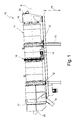
figure 1 shows a schematic side elevation view of the dryer according to the present invention; -
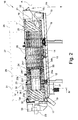
figure 2 shows a schematic, longitudinal and partial section view of the dryer according tofigure 1 ; -
figure 3 shows an enlarged detail of the dryer offigure 2 ; -
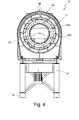
figure 4 shows a schematic partial section view of the dryer according to the present invention according to plane IV-IV offigure 2 ; -
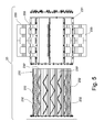
figure 5 shows a schematic side exploded view of the tubular body of the dryer according to the present invention; -
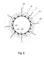
figure 6 shows a schematic front view of the tubular body of the dryer according to the present invention; -
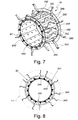
figure 7 shows a schematic axonometric view of the auxiliary tubular body of the dryer according to the present invention without the second tubular wall which externally delimits it; -
figure 8 shows a schematic front view of the auxiliary tubular body of the dryer according to the present invention. - The
dryer 10 comprises acylinder 11 rotatably supported about its longitudinal axis A bysupports 12 mounted on aframe 13 resting on the ground. - Motor means 14 are mounted on the
frame 13 which, through driving means 15, for example of the gear type, drive thecylinder 11 in rotation about its longitudinal axis A. - As it is clear from
figures 1 and2 , the longitudinal axis A of thecylinder 11 is inclined with respect to the horizontal plane or the support plane of theframe 13 by an angle α in the order of a few degrees, typically 3°. - The
cylinder 11 is delimited at its opposite ends by two heads, respectively afirst head 16 at higher height and asecond head 17 at smaller height. - An
inlet mouth 18 of a mixture of virgin inerts and recovery materials (RAP, Reclaimed Asphalt Pavement) to be dried is defined at thefirst head 16, whereas anoutlet mouth 19 of the dried mixture is defined at thesecond head 17. - The heat required for drying is generated by at least one
burner 20 associated with thesecond head 17 and placed coaxially to the longitudinal axis A of thecylinder 11 inside which it directs the flame. - On the other hand, an outlet opening 21 of the discharge smokes of the
dryer 10 is obtained at thefirst head 16, the outlet opening communicates with asuction chamber 22 in turn associable with an assembly for sucking and treating the discharge smokes of thedryer 10 and not shown in detail as it is known by the man skilled in the art. - Deflecting baffles and/or walls are provided at the outlet opening 21 which are adapted to prevent fine powders of the treated materials pulled by the sucked smokes from reaching the smokes filter assembly arranged downstream of the
dryer 10 and which are the object of a co-pending application to the same Applicant. - Means for mixing and moving the inerts and the recovery materials treated are mounted on the inner side surface of the
cylinder 11, which means mix and accompany them in their advance motion along theentire cylinder 11, from theinlet mouth 18 to theoutlet mouth 19. The shape and the arrangement of the mixing and moving means vary along thecylinder 11 according to the different treatment zones that may be found inside it and as it will be described hereinafter. - As it is seen in
figures 1 and2 , theinlet mouth 18 and theoutlet mouth 19 of the mixture are obtained at the opposite ends (heads) of thecylinder 11, as well as theburner 20 and the outlet opening 21 of the discharge smokes are placed at the opposite ends (heads) of thecylinder 11; this allows the entire length of thecylinder 11 to be used for the thermal exchange between the heat generated by theburner 20 and the mixture treated. - A
tubular body 23, open at theopposite ends cylinder 11, and placed coaxially to the longitudinal axis A of thecylinder 11 with one of itsopen ends 23a facing burner 20 and at a definite distance therefrom and with the oppositeopen end 23b facing thefirst head 16. - The
tubular body 23 has a maximum diameter smaller than the inner diameter of thecylinder 11 so as to form an annular interspace with it crossed on the bottom by the drying mixture. - The combustion smokes and the flame generated by the
burner 20 are axially directed into thetubular body 23, inside which the drying smokes of the drying mixture, which advances on the bottom of the interspace defined betweencylinder 11 and thetubular body 23, also without impacting the latter, are furthermore sucked by dynamic effect. - A first peculiar feature of the present invention consists in that in succession to the
tubular body 23 and downstream of it with respect to the flow sense of the combustion and drying smokes, an auxiliarytubular body 24 is provided, which is also open at theopposite ends cylinder 11 and placed coaxially to the longitudinal axis A of thesame cylinder 11. - The auxiliary
tubular body 24 is arranged with one of its two oppositeopen ends 24a facing theopen end 23b of thetubular body 23 opposite to that23a facing burner 20 and at a definite distance from it, and the opposedopen end 24b directed towards the inside ofcylinder 11 and facing thefirst head 16. - The auxiliary
tubular body 24 has a maximum diameter smaller than the inner diameter ofcylinder 11 and defines with it an interspace crossed by the drying mixture. - The combustion and drying smokes coming out of the
tubular body 23 are directed into thetubular body 24, inside which the smokes external thereto are also sucked by dynamic effect. - The
tubular body 23 and the auxiliarytubular body 24 define each a respective hot combustion and/or post-combustion chamber of the combustion smokes and of the drying smokes, where the latter are generated by the fraction of recovery material (RAP) present in the drying mixture and, in particular, by the aged bitumen present therein. - According to a further peculiar feature of the present invention, both the
tubular body 23 and the auxiliarytubular body 24 are made of heat resistant steel, also of different type, the second one having to withstand lower temperatures than the first one. - In a preferred embodiment, the
tubular body 23 is made of AISI 310 S steel, whereas the auxiliarytubular body 24 is made of 304-306 steel. - The
tubular body 23 comprises a firsttubular wall 230 and a secondtubular wall 231 of larger diameter than the firsttubular wall 230 and arranged externally and coaxially to it. - The first
tubular wall 230 and the secondtubular wall 231 are fixed to each other and each of them consists in turn of a plurality of longitudinal sectors, respectively 230' and 231', arranged side by side and coupled to each other. - An interspace is defined between the first
tubular wall 230 and the secondtubular wall 231 wherein a plurality ofstiffening elements 232 is fixed, which consist of ribs, sticks, straps or the like shaped or arranged so as to form a succession of V, S, Z or the like along generatrixes of thetubular body 23. - In particular, the
stiffening elements 232 are distributed into rows parallel to the longitudinal axis of thetubular body 23, where thestiffening elements 232 of each row are alternately oriented according to two different inclined directions with respect to the longitudinal axis A to form a series of V with opposite vertices. -
Brackets 233 for anchoring to the inner side surface ofcylinder 11 extend from the outer side surface of thetubular body 23. - Likewise, the auxiliary
tubular body 24 comprises a firsttubular wall 240 and a secondtubular wall 241 of larger diameter than the firsttubular wall 240 and arranged externally and coaxially to it. - The first
tubular wall 240 and the secondtubular wall 241 are fixed to each other and each of them consists in turn of a plurality of longitudinal sectors, respectively 240' and 241', arranged side by side and coupled to each other. - An interspace is defined between the first
tubular wall 240 and the secondtubular wall 241 wherein a plurality of stiffeningelements 242 is fixed, which consist of ribs, sticks, straps or the like shaped or arranged so as to form a succession of V, S, Z or the like along generatrixes of the auxiliarytubular body 24. - In particular, the stiffening
elements 242 are distributed into rows parallel to the longitudinal axis of the auxiliarytubular body 24, where thestiffening elements 242 of each row are alternately oriented according to two different inclined directions with respect to the longitudinal axis A to form a series of V with opposite vertices. -
Angles 243 for anchoring to the inner side surface ofcylinder 11 extend from the outer side surface of the auxiliarytubular body 24. - In a preferred embodiment, both the first
tubular wall 240, i.e. the component sectors 240' thereof, and the secondtubular wall 241, i.e. the component sectors 241' thereof, have a plurality of distributed throughholes 244, mutually spaced at a constant pitch, along the entire length of the auxiliarytubular body 24, in order to prevent the wall temperature of the auxiliarytubular body 24 from exceeding a threshold value depending on the type of material, in particular steel, it is made of. - It is not excluded that similar through holes may be made into the walls of the
tubular body 23. - The assembly consisting of the
burner 20, of thetubular body 23 and of the auxiliarytubular body 24 forms a combustor or post-combustor assembly; in particular, thetubular body 23 and the auxiliarytubular body 24 form two hot chambers into which the flame and the combustion smokes are directed and the drying smokes, generated by the recovery materials (RAP) or in any case the smokes present insidecylinder 11, are sucked by dynamic effect, allowing the combustion (oxidation) of the organic substances contained therein to be completed. - The distance between the
tubular body 23, or better between itsopen end 23a, andburner 20, as well as the distance between thetubular body 23 and the auxiliarytubular body 24, or better between their open and mutually facing ends, respectively 23b and 24a, is determined so as to ensure the desired fume suction effect, in particular of the drying smokes, inside them. - Different mixture treatment zones follow in succession inside the
cylinder 11 and along its longitudinal development at different temperatures which are progressively increasing as the mixture introduced through theinlet mouth 18 advances towards theoutlet mouth 19. - In particular, starting from the
first head 16 at which theinlet mouth 18 of the inerts and recovery materials (RAP) mixture to be dried is defined, continuing towards thesecond head 17 at which theoutlet mouth 19 of the dried mixture is defined, follow in succession: - a
first inlet area 25 of the mixture at which a plurality ofhelical blades 26 is distributed on the inner surface of thecylinder 11; - a second evaporating
area 27 of the moisture present in the mixture at which a plurality of risingcups 28 of the inerts and of the recovery material (RAP) falling rain-wise is distributed on the inner surface of thecylinder 11; - a
third area 29 for mixing the inerts and the recovery material (RAP) at which a plurality of mixing blades 30 (object of a co-pending patent application to the same Applicant) is distributed on the inner surface of thecylinder 11; and - a
fourth area 31 for the final heating of the mixture at which a plurality ofhelical blades 32 is distributed on the inner surface of thecylinder 11. - As it is clear from
figures 1 and2 , in a preferred embodiment, thetubular body 23 extends along at least one tract of thefourth heating area 31 and the auxiliarytubular wall 24 extends along at least one tract of thethird mixing area 29. - The
dryer 10 further comprises an assembly for heating the comburent air fed toburner 20. Such a heating unit comprises apre-heating chamber 33 which extends behind thesecond head 17 and wherein the body of theburner 20 is housed. - A
shell 34 is mounted around thecylinder 11, by at least one tract of the length of thefourth area 31, the one at the highest temperature; saidshell 34 forms, around thecylinder 11, aninterspace 35 which at one end communicates with thepre-heating chamber 33 and at the opposite end with one ormore inlet openings 36 of the ambient air. - A
suction fan 37 is mounted belowframe 13 and communicates with thepre-heating chamber 33 so as to suck ambient air into it throughinterspace 35. Moreover, sensing means of the sucked air temperature, such as for example a thermal probe, and means for measuring the sucked air flow rate, such as for example a Pitot tube, so as to control and adjust the operation ofburner 20, are provided. - The air sucked from the external environment first crosses the
interspace 35 wherefrom it then enters thepre-heating chamber 33 to then be fed intocylinder 11 for supporting the combustion of the fuel injected by theburner 20. - The heat of the walls of
cylinder 11, which at full operation reach temperatures of about 500-550°C, is yield by convection to the sucked air the temperature of which is on the average increased by about 45-50°C before being injected into thecylinder 11, with clear advantages in terms of combustion efficiency. Advantageously, the delivery air volume is less than that sucked, causing an increase in the air density which favors the combustion. - With reference to the annexed figures, the operation of the dryer is as follows.
- The virgin inert material and the recovery material (RAP) are fed into
cylinder 11 through theinlet mouth 18. - The materials thus fed cross the
first area 25 being mixed and blended by thehelical blades 26. - The average temperature inside
cylinder 11 at thefirst area 25 is generally in the order of 120-150°C. - The mixture then advances along the
second zone 27, wherein there is an average temperature in the order of 280-300°C, where the humidity contained in the materials and in particular in the recovery materials (RAP) evaporates. - The rising cups 28, or similar lifting means, for example blade or cup means, lift the materials, which fall "rain-wise"; the mixing and blending of the virgin inert materials with the recovery materials are thus favored. In particular, the bitumen fraction present in the recovery materials (RAP) softens, favoring the bond with virgin inert materials; aggregates of virgin inert materials and of recovery materials (RAP) are thus formed.
- A further mixing of the materials occurs along the
third area 29 by themixing blades 30 which, thanks to their particular arrangement and shape, object of a co-pending application to the same Applicant, impart a controlled advance motion to the materials such as to favor the forming of a substantially homogeneous mixture. - Along such
third area 29, the mixture advances into the interspace defined between thecylinder 11 and the auxiliarytubular body 24, without contacting the latter. - Inside such interspace there is a maximum average temperature in the order of 450°C, whereas inside the auxiliary
tubular body 24 there is a maximum average temperature in the order of 550°C. - Finally, the mixture advances into the fourth
final heating area 31 to exit from theoutlet mouth 19 at an average temperature of about 180-200°C. - The flame of
burner 20, the average temperature of which is in the order of 1000-1400°C, flows into suchfourth area 31. - It is noted, in particular, that the mixture advances without contacting the flame or the outer wall of the
tubular body 23. - The efficiency of the
burner 20 is improved thanks to the pre-heating of the comburent air. - The ambient air is in fact sucked into the
interspace 35 and conveyed into thepre-heating chamber 33, where it heats by convection with an increase of about 40-45°C, before being fed intocylinder 11. - The air flow rate and its temperature, moreover, are measured and controlled.
- The flame and the combustion smokes are directed into the tubular body 23 (inside which there is a maximum average temperature in the order of 800-900°C) and therefrom into the auxiliary
tubular body 24. - Moreover the drying smokes, i.e. the smokes generated by the recovery material, are sucked by dynamic effect into the
tubular body 23 and the auxiliarytubular body 24. - The two hot chambers in a sequence, respectively formed by the
tubular body 23 and by thetubular body 24, are crossed by the combustion and drying smokes and the volatile organic substances present therein oxidize thanks to the heat present inside such two hot chambers and their walls. - The smokes are then vented through the
outlet opening 21 andchamber 22 and conveyed in a treatment and removal assembly. - The dryer object of the present invention has the advantage of further reducing, compared to the known dryers, the percentages of volatile organic substances (VOC, TOC) present in the discharge smokes in compliance with the regulations in force, irrespective of the nature of the virgin inert materials and of the recovery materials (RAP) treated and also for percentages of recovery materials (RAP) higher than 25% to the limit of the order of 40%.
- In fact, the provision of a further auxiliary
tubular body 24 downstream of and in a sequence to thetubular body 23, on one hand increases the forced suction effect of the combustion and drying smokes therein and, on the other hand, it facilitates the completion of the oxidation reactions of the volatile organic substances; the smokes, in fact, are forced to cross two hot chambers in a sequence. - Such an effect is further increased thanks to the realization of both the
tubular body 23, and oftubular body 24, anymore in refractory material but in heat resistant steel. - Comparative experiments have showed that, under the same conditions, a dryer according to the present invention leads to a VOC content reduction by at least one order of magnitude compared to a dryer as object of the previous patent application
MI2008A02312 - The provision of
axial stiffening elements tubular body 23 and of the auxiliarytubular body 24 limits the deformations their walls would be subject due to the temperatures reached therein and to the alternation of thermal cycles. - Also, the presence of through holes along the walls of the auxiliary
tubular body 24 prevents the same from exceeding a threshold temperature depending on the material (steel) they are made of and typically in the order of 550°C to prevent hazards of oxidation of the same walls. - Making the
tubular body 23 and the auxiliarytubular body 24 of steel prevents problems of crumbling and crushing of refractory coatings. - Finally, the pre-heating of the comburent air improves the combustion efficiency in terms of fuel saving in the order of 10%-20%.
- It is noted that the temperatures indicated in the present description are purely indicative, depending on the flow rate and the type of both the virgin inert material and the recovery material (RAP), on the fuel used, on the ambient air temperature and on the temperature the material must be heated to.
- Several changes and variations can be made to the dryer thus conceived, all falling within the invention; moreover, all details can be replaced with technically equivalent elements. In the practice, the materials used as well as the sizes, can be whatever, according to the technical requirements.
Claims (10)
- Rotary cylinder dryer (10) for mixtures of virgin inerts and recovery materials (RAP) for preparing bituminous conglomerates, comprising a cylinder (11) which is associable with motor means (14) suitable for driving it in rotation around its own longitudinal axis (A) and which is provided with two opposite heads (16, 17), an inlet mouth (18) of a mixture of virgin inerts and of recovery materials (RAP) to be dried and which is defined at one of said two heads (16), an outlet mouth (19) of the dried mixture and which is defined at the other one of said two heads (17), at least one burner (20) associated with said head (17) at which said outlet mouth (19) is defined and a tubular body (23), open at the opposite ends (23a, 23b), fixed inside said cylinder (11) and placed coaxially to the longitudinal axis (A) of said cylinder (11), with one of its open ends (23a) facing said burner (20) and at a definite distance from it, characterized in that it comprises at least one auxiliary tubular body (24), open at the opposite ends (24a,24b), fixed inside said cylinder (11) and placed coaxially the longitudinal axis (A) of said cylinder and in succession to said tubular body (23).
- Dryer (10) according to claim 1, characterized in that said auxiliary tubular body (24) has one of its open ends (24a) facing the open end (23b) of said tubular body (23) opposite to that (23a) facing said burner (20) and at a definite distance from it, and the opposite end (24b) directed towards the inside of said cylinder (11).
- Dryer (10) according to claim 1 or 2, characterized in that at least one of said tubular body (23) and said auxiliary tubular body (24) is made of heat-resistant steel.
- Dryer (10) according to one or more of the preceding claims, characterized in that each of said tubular body (23) and said auxiliary tubular body (24) comprises a first tubular wall (230; 240), a second tubular wall (231; 241) having diameter greater than said first tubular wall (230; 240) and which is placed coaxially and externally to said first tubular wall (230; 240) and fixed to it and a plurality of stiffening elements (232; 242) fixed between said first tubular wall (230; 240) and said second tubular wall (231; 241).
- Dryer (10) according to claim 4, characterized in that said stiffening elements (232; 242) comprise ribs or similar which are shaped or placed so as to form an alternation of V, S, Z or similar along generatrixes of said tubular body (23) or of said auxiliary tubular body (24).
- Dryer (10) according to claim 4 or 5, characterized in that on at least a portion of said first tubular wall (230; 240) and/or of said second tubular wall (231; 241) a plurality of through holes is distributed (244).
- Dryer (10) according to one or more claims from 4 to 6, characterized in that said first tubular wall (230; 240) and/or said second tubular wall (231; 241) is formed by a plurality of longitudinal sectors (231'; 241') arranged side by side to each other.
- Dryer (10) according to one or more of the preceding claims, characterized in that starting from said head (16), at which said inlet mouth (18) of the mixture of inerts and recovery materials to be dried is defined, towards said head (17), at which said outlet mouth (19) of the dried mixture is defined, treatment areas with a progressively increasing temperature follow in sequence to each other, of which a first inlet area (25), at which on the internal surface of said cylinder a plurality of helical blades (26) is distributed, a second evaporating area (27) of the moisture present in said mixture and at which, on the internal surface of said cylinder a plurality of rising cups (28) of said inerts and of said recovery material (RAP) is distributed, a third area (29) for mixing said inerts and said recovery material (RAP) at which on the internal surface of said cylinder a plurality of mixing blades (30) is distributed, and a fourth area (31) for finally heating the mixture and at which on the internal surface of said cylinder a plurality of helical blades (32) is distributed, wherein said tubular body (23) extends along at least one tract of said fourth heating area (31) and said auxiliary tubular body (24) extends along at least one tract of said third mixing area (29).
- Dryer (10) according to one or more of the preceding claims, characterized in that it comprises a chamber (33) for pre-heating the comburent air fed to said burner (20), chamber which extends behind said head (17), at which said burner (20) is associated and which communicates with an interspace (35) for sucking the ambient air which is defined between a tract of the lateral external surface of said cylinder (11) and a shell (34) external to it and which is provided with at least one inlet opening (36) of the ambient air, wherein said pre-heating chamber (33) is associated with a suction fan (37).
- Dryer (10) according to claim 9, characterized in that said suction fan (37) is mounted below said cylinder (11), at said shell (34).
Applications Claiming Priority (1)
| Application Number | Priority Date | Filing Date | Title |
|---|---|---|---|
| IT001352A ITMI20111352A1 (en) | 2011-07-20 | 2011-07-20 | ROTARY CYLINDER DRYER FOR MIXTURES OF VIRGIN INERTES AND RECOVERY MATERIALS FOR THE PREPARATION OF BITUMINOUS CONGLOMERATES |
Publications (1)
| Publication Number | Publication Date |
|---|---|
| EP2549016A1 true EP2549016A1 (en) | 2013-01-23 |
Family
ID=44511242
Family Applications (1)
| Application Number | Title | Priority Date | Filing Date |
|---|---|---|---|
| EP12177181A Withdrawn EP2549016A1 (en) | 2011-07-20 | 2012-07-19 | Rotary cylinder dryer for mixtures of virgin inerts and recovery materials for preparing bituminous conglomerates |
Country Status (4)
| Country | Link |
|---|---|
| EP (1) | EP2549016A1 (en) |
| CN (1) | CN102889760A (en) |
| IT (1) | ITMI20111352A1 (en) |
| RU (1) | RU2012130864A (en) |
Cited By (5)
| Publication number | Priority date | Publication date | Assignee | Title |
|---|---|---|---|---|
| CN103591778A (en) * | 2013-10-11 | 2014-02-19 | 唐山市神州机械有限公司 | Rotary drum drying device |
| ITUB20156088A1 (en) * | 2015-12-02 | 2017-06-02 | Marco Chignola | DEVICE FOR DRYING AND OVERHEATING OF INERT MATERIAL |
| WO2019111073A1 (en) * | 2017-12-04 | 2019-06-13 | Bernardi Impianti S.R.L. | Gasification apparatus |
| EP4246071A1 (en) * | 2022-03-16 | 2023-09-20 | Benninghoven Zweigniederlassung der Wirtgen Mineral Technologies GmbH | Flame protection device and drying drum with such a flame protection device |
| EP4357710A1 (en) * | 2022-10-20 | 2024-04-24 | Benninghoven Zweigniederlassung der Wirtgen Mineral Technologies GmbH | Flame protection device for a burner, lamella for such a flame protection device and drying drum with such a flame protection device |
Families Citing this family (6)
| Publication number | Priority date | Publication date | Assignee | Title |
|---|---|---|---|---|
| CN103103908A (en) * | 2013-02-01 | 2013-05-15 | 福建南方路面机械有限公司 | Asphalt mixture drying drum |
| CN103397589A (en) * | 2013-08-04 | 2013-11-20 | 郴州市三联路面机械有限责任公司 | Roller used for heating, drying and continuous stirring to produce thermal regeneration mixture |
| CN104930831B (en) * | 2015-06-28 | 2019-01-22 | 福建省南安市海特机械有限公司 | A kind of numerical control and energy saving muffle dryer |
| CN105258469B (en) * | 2015-11-26 | 2017-11-03 | 四川东立科技股份有限公司 | Ferrous sulfate heptahydrate dryer |
| CN105970771B (en) * | 2016-07-08 | 2018-08-21 | 山东省路桥集团有限公司 | The hot in-plant reclaimed drying drum of pitch |
| CN116905313B (en) * | 2023-09-12 | 2023-12-05 | 福建省铁拓机械股份有限公司 | Double-return-stroke internal circulation asphalt mixture drying roller |
Citations (4)
| Publication number | Priority date | Publication date | Assignee | Title |
|---|---|---|---|---|
| US4919538A (en) * | 1989-07-26 | 1990-04-24 | Swisher Jr George W | Drum mixer having a combined mixing and heating zone |
| US5664881A (en) * | 1993-11-16 | 1997-09-09 | Maxam Equipment, Inc. | Counter-flow asphalt plant with multi-stage combustion zone overlapping the mixing zone |
| EP1624109A1 (en) * | 2004-08-03 | 2006-02-08 | Ghirardelli Plants SRL | Apparatus for recycling asphalt for production plants of bitumimous conglomerate |
| EP2202473A1 (en) | 2008-12-23 | 2010-06-30 | Bernardi Impianti International S.P.A. | Desiccator for inert material |
-
2011
- 2011-07-20 IT IT001352A patent/ITMI20111352A1/en unknown
-
2012
- 2012-07-19 RU RU2012130864/06A patent/RU2012130864A/en not_active Application Discontinuation
- 2012-07-19 EP EP12177181A patent/EP2549016A1/en not_active Withdrawn
- 2012-07-20 CN CN 201210252007 patent/CN102889760A/en active Pending
Patent Citations (4)
| Publication number | Priority date | Publication date | Assignee | Title |
|---|---|---|---|---|
| US4919538A (en) * | 1989-07-26 | 1990-04-24 | Swisher Jr George W | Drum mixer having a combined mixing and heating zone |
| US5664881A (en) * | 1993-11-16 | 1997-09-09 | Maxam Equipment, Inc. | Counter-flow asphalt plant with multi-stage combustion zone overlapping the mixing zone |
| EP1624109A1 (en) * | 2004-08-03 | 2006-02-08 | Ghirardelli Plants SRL | Apparatus for recycling asphalt for production plants of bitumimous conglomerate |
| EP2202473A1 (en) | 2008-12-23 | 2010-06-30 | Bernardi Impianti International S.P.A. | Desiccator for inert material |
Cited By (7)
| Publication number | Priority date | Publication date | Assignee | Title |
|---|---|---|---|---|
| CN103591778A (en) * | 2013-10-11 | 2014-02-19 | 唐山市神州机械有限公司 | Rotary drum drying device |
| CN103591778B (en) * | 2013-10-11 | 2015-03-18 | 唐山市神州机械有限公司 | Rotary drum drying device |
| ITUB20156088A1 (en) * | 2015-12-02 | 2017-06-02 | Marco Chignola | DEVICE FOR DRYING AND OVERHEATING OF INERT MATERIAL |
| WO2019111073A1 (en) * | 2017-12-04 | 2019-06-13 | Bernardi Impianti S.R.L. | Gasification apparatus |
| EP4246071A1 (en) * | 2022-03-16 | 2023-09-20 | Benninghoven Zweigniederlassung der Wirtgen Mineral Technologies GmbH | Flame protection device and drying drum with such a flame protection device |
| EP4357710A1 (en) * | 2022-10-20 | 2024-04-24 | Benninghoven Zweigniederlassung der Wirtgen Mineral Technologies GmbH | Flame protection device for a burner, lamella for such a flame protection device and drying drum with such a flame protection device |
| EP4513119A3 (en) * | 2022-10-20 | 2025-03-26 | Benninghoven Zweigniederlassung der Wirtgen Mineral Technologies GmbH | Flame protection device for a burner, lamella for such a flame protection device and drying drum with such a flame protection device |
Also Published As
| Publication number | Publication date |
|---|---|
| ITMI20111352A1 (en) | 2013-01-21 |
| CN102889760A (en) | 2013-01-23 |
| RU2012130864A (en) | 2014-01-27 |
Similar Documents
| Publication | Publication Date | Title |
|---|---|---|
| EP2549016A1 (en) | Rotary cylinder dryer for mixtures of virgin inerts and recovery materials for preparing bituminous conglomerates | |
| US5203693A (en) | Rotary drum dryer having internal flights | |
| US7581871B2 (en) | Counter-flow drum mixer asphalt plant method for two stage mixing | |
| EP2202473A1 (en) | Desiccator for inert material | |
| JPH10510617A (en) | Drum dryer with crushed stone cooling shield member | |
| US4954995A (en) | Device and method for preparing bituminous products | |
| KR102512498B1 (en) | Sludge drying apparatus | |
| US4955722A (en) | Appliance for the preparation of bituminous coated products with a stationary mixer | |
| CA2585626A1 (en) | Pre-combustion mix drum | |
| CN107824258A (en) | A kind of blue and white porcelain is fired and uses kaolin fine gtinding screening plant | |
| EP3551802B1 (en) | Plant for the production and distribution of bituminous conglomerates | |
| US5380084A (en) | Asphalt drum mixer with self-scouring drum | |
| US5380082A (en) | Asphalt drum mixer with curved scoop-like mixing tips | |
| KR101128685B1 (en) | Recycle drier in apparatus of regenerating waste ascon | |
| CN200996777Y (en) | Multifunctional continuous fast toaster | |
| EP2549017A1 (en) | Rotary cylinder dryer for mixtures of virgin inerts and recovery materials for preparing bituminous conglomerates | |
| GB2506440A (en) | Apparatus for drying particulate material | |
| RU90182U1 (en) | UNIVERSAL GRAIN DRYER | |
| CN209368632U (en) | Asphalt material carrier bar conveys heating mechanism | |
| JP4724466B2 (en) | Asphalt plant dryer | |
| JP2013142243A (en) | Asphalt plant | |
| CN201962576U (en) | Rotary drum for drying stones | |
| CN110904799B (en) | A differential double-horizontal-shaft asphalt mixture mixing drum and road maintenance equipment | |
| KR101588864B1 (en) | Chaff burner | |
| CN120575462A (en) | Industrial equipment for manufacturing asphalt macadam |
Legal Events
| Date | Code | Title | Description |
|---|---|---|---|
| PUAI | Public reference made under article 153(3) epc to a published international application that has entered the european phase |
Free format text: ORIGINAL CODE: 0009012 |
|
| AK | Designated contracting states |
Kind code of ref document: A1 Designated state(s): AL AT BE BG CH CY CZ DE DK EE ES FI FR GB GR HR HU IE IS IT LI LT LU LV MC MK MT NL NO PL PT RO RS SE SI SK SM TR |
|
| AX | Request for extension of the european patent |
Extension state: BA ME |
|
| STAA | Information on the status of an ep patent application or granted ep patent |
Free format text: STATUS: THE APPLICATION IS DEEMED TO BE WITHDRAWN |
|
| 18D | Application deemed to be withdrawn |
Effective date: 20130724 |