EP2548799A1 - Aerodynamic coefficient estimation device and control surface failure/damage detection device - Google Patents
Aerodynamic coefficient estimation device and control surface failure/damage detection device Download PDFInfo
- Publication number
- EP2548799A1 EP2548799A1 EP11756348A EP11756348A EP2548799A1 EP 2548799 A1 EP2548799 A1 EP 2548799A1 EP 11756348 A EP11756348 A EP 11756348A EP 11756348 A EP11756348 A EP 11756348A EP 2548799 A1 EP2548799 A1 EP 2548799A1
- Authority
- EP
- European Patent Office
- Prior art keywords
- failure
- damage
- deflection angle
- control surface
- aerodynamic coefficient
- Prior art date
- Legal status (The legal status is an assumption and is not a legal conclusion. Google has not performed a legal analysis and makes no representation as to the accuracy of the status listed.)
- Granted
Links
Images


Classifications
-
- G—PHYSICS
- G01—MEASURING; TESTING
- G01M—TESTING STATIC OR DYNAMIC BALANCE OF MACHINES OR STRUCTURES; TESTING OF STRUCTURES OR APPARATUS, NOT OTHERWISE PROVIDED FOR
- G01M9/00—Aerodynamic testing; Arrangements in or on wind tunnels
- G01M9/06—Measuring arrangements specially adapted for aerodynamic testing
-
- B—PERFORMING OPERATIONS; TRANSPORTING
- B64—AIRCRAFT; AVIATION; COSMONAUTICS
- B64C—AEROPLANES; HELICOPTERS
- B64C13/00—Control systems or transmitting systems for actuating flying-control surfaces, lift-increasing flaps, air brakes, or spoilers
-
- G—PHYSICS
- G01—MEASURING; TESTING
- G01M—TESTING STATIC OR DYNAMIC BALANCE OF MACHINES OR STRUCTURES; TESTING OF STRUCTURES OR APPARATUS, NOT OTHERWISE PROVIDED FOR
- G01M9/00—Aerodynamic testing; Arrangements in or on wind tunnels
- G01M9/08—Aerodynamic models
-
- B—PERFORMING OPERATIONS; TRANSPORTING
- B64—AIRCRAFT; AVIATION; COSMONAUTICS
- B64D—EQUIPMENT FOR FITTING IN OR TO AIRCRAFT; FLIGHT SUITS; PARACHUTES; ARRANGEMENT OR MOUNTING OF POWER PLANTS OR PROPULSION TRANSMISSIONS IN AIRCRAFT
- B64D45/00—Aircraft indicators or protectors not otherwise provided for
- B64D2045/0085—Devices for aircraft health monitoring, e.g. monitoring flutter or vibration
-
- G—PHYSICS
- G01—MEASURING; TESTING
- G01C—MEASURING DISTANCES, LEVELS OR BEARINGS; SURVEYING; NAVIGATION; GYROSCOPIC INSTRUMENTS; PHOTOGRAMMETRY OR VIDEOGRAMMETRY
- G01C23/00—Combined instruments indicating more than one navigational value, e.g. for aircraft; Combined measuring devices for measuring two or more variables of movement, e.g. distance, speed or acceleration
-
- G—PHYSICS
- G01—MEASURING; TESTING
- G01C—MEASURING DISTANCES, LEVELS OR BEARINGS; SURVEYING; NAVIGATION; GYROSCOPIC INSTRUMENTS; PHOTOGRAMMETRY OR VIDEOGRAMMETRY
- G01C23/00—Combined instruments indicating more than one navigational value, e.g. for aircraft; Combined measuring devices for measuring two or more variables of movement, e.g. distance, speed or acceleration
- G01C23/005—Flight directors
-
- G—PHYSICS
- G05—CONTROLLING; REGULATING
- G05D—SYSTEMS FOR CONTROLLING OR REGULATING NON-ELECTRIC VARIABLES
- G05D1/00—Control of position, course, altitude or attitude of land, water, air or space vehicles, e.g. using automatic pilots
- G05D1/0055—Control of position, course, altitude or attitude of land, water, air or space vehicles, e.g. using automatic pilots with safety arrangements
- G05D1/0077—Control of position, course, altitude or attitude of land, water, air or space vehicles, e.g. using automatic pilots with safety arrangements using redundant signals or controls
-
- G—PHYSICS
- G08—SIGNALLING
- G08G—TRAFFIC CONTROL SYSTEMS
- G08G5/00—Traffic control systems for aircraft
- G08G5/20—Arrangements for acquiring, generating, sharing or displaying traffic information
- G08G5/21—Arrangements for acquiring, generating, sharing or displaying traffic information located onboard the aircraft
-
- G—PHYSICS
- G08—SIGNALLING
- G08G—TRAFFIC CONTROL SYSTEMS
- G08G5/00—Traffic control systems for aircraft
- G08G5/20—Arrangements for acquiring, generating, sharing or displaying traffic information
- G08G5/26—Transmission of traffic-related information between aircraft and ground stations
Definitions
- the present invention relates to an aerodynamic coefficient estimation device and a control surface failure/damage detection device using the aerodynamic coefficient estimation device, and particularly relates to an aerodynamic coefficient estimation device that estimates aerodynamic coefficients indicating the aerodynamic characteristics of an aircraft and a control surface failure/damage detection device that detects a failure of or damage to control surfaces of the aircraft using the estimated aerodynamic coefficients.
- 2003-175896 discloses a control surface failure/damage detection device that estimates aerodynamic coefficients using the iterative least square technique, performs computation on the estimated aerodynamic coefficients using the neural network technique to calculate final aerodynamic coefficients, and detects a failure or the like of control surfaces by software based on the calculated final aerodynamic coefficients. Also, a method in which hardware such as an optical fiber or an electric wire is laid on an aircraft to directly detect damage to control surfaces is conceivable.
- the present invention has been made in order to solve the above-described problems, and it is an object thereof to provide an aerodynamic coefficient estimation device that can compute highly reliable aerodynamic coefficients estimates and to provide a control surface failure/damage detection device that can accurately detect control surface failure/damage by computing highly reliable aerodynamic coefficient estimates while reducing a discomfort for passengers.
- the present invention provides an aerodynamic coefficient estimation device including a deflection angle command signal generation means that generates a deflection angle command signal for estimating an aerodynamic coefficient indicating an aerodynamic characteristic of an airframe, a kinetic state quantity acquisition means that acquires a kinetic state quantity of the airframe that is obtained as a result of a control surface provided on the airframe being moved based on the deflection angle command signal, a candidate value calculation means that calculates candidate values for estimating the aerodynamic coefficient from the kinetic state quantity using two or more different estimations, and an aerodynamic coefficient estimate determination means that determines an aerodynamic coefficient estimate based on the candidate values.
- the deflection angle command signal generation means generates a deflection angle command signal that moves control surfaces so as to impart a certain degree of motion to the airframe in order to estimate an aerodynamic coefficient, and the control surfaces are moved in accordance with the deflection angle command signal.
- the kinetic state quantity acquisition means acquires kinetic state quantities such as the angle of attack, the angle of sideslip, the airspeed, the angular speed, the attitude angle, and the deflection angle of the airframe to which the motion has been imparted as a result of the control surfaces being moved, from a sensor or the like provided on the airframe in advance.
- the candidate value calculation means calculates candidate values serving as candidates for calculating an aerodynamic coefficient estimate based on the kinetic state quantities using two or more different estimations, for example, two or more different estimations selected from an extended Kalman filter, an unscented Kalman filter, a Fourier transform regression technique, a neural network technique, a particle filter, and other techniques.
- the aerodynamic coefficient estimate determination means finally determines the aerodynamic coefficient estimate by selecting or computing the most appropriate value for the aerodynamic coefficient estimate from these candidate values. In this manner, candidate values for an aerodynamic coefficient estimate are calculated by two or more different estimations, and then the aerodynamic coefficient estimate is finally determined from the candidate values. This enables redundancy to be introduced into computation of the aerodynamic coefficient estimate and therefore a highly reliable aerodynamic coefficient to be computed.
- the aerodynamic coefficient estimate determination means determines an average or a median of the candidate values as an aerodynamic coefficient estimate.
- the aerodynamic coefficient estimation device since an average or a median of the candidate values that have been computed by the different estimations is determined as the aerodynamic coefficient estimate, redundancy can be introduced into computation of the aerodynamic coefficient estimate, and therefore, a highly reliable aerodynamic coefficient can be computed.
- the aerodynamic coefficient estimate determination means determines a candidate value corresponding to one of the reproduced values of the kinetic state quantity that are computed respectively based on the candidate values as an aerodynamic coefficient estimate, the one reproduced value being the closest to the kinetic state quantity.
- a reproduced value of the kinetic state quantity can be computed using each candidate value.
- the reproduced values of the kinetic state quantity obtained from the respective candidate values are compared with the actual kinetic state quantity acquired by the kinetic state quantity acquisition means, and the candidate value corresponding to the reproduced value that is the closest to the actual kinetic state quantity is determined as the aerodynamic coefficient estimate. This enables redundancy to be introduced into computation of the aerodynamic coefficient estimate and therefore a highly reliable aerodynamic coefficient to be computed.
- a control surface failure/damage detection device of the present invention includes a failure/damage possibility judging that judges the possibility of control surface failure/damage and a control surface failure/damage detection means that detects which control surface suffers a failure or damage based on an aerodynamic coefficient estimate estimated by the aerodynamic coefficient estimation device if the failure/damage possibility judging means judges that there is a possibility that control surface failure/damage may occur.
- control surface failure/damage detection device of the present invention if it is judged that there is a possibility that control surface failure/damage may occur, an aerodynamic coefficient estimate is calculated, and which control surface suffers the failure or damage is detected based on this estimate.
- a failure of or damage to a control surface can be accurately detected by continuously monitoring control surface failure/damage while minimizing unwanted motion such as unwanted swaying of the airframe and thereby reducing the discomfort for the passengers.
- the failure/damage possibility judging means includes another deflection angle command generation signal that generates a deflection angle command signal for moving the control surface such that the airframe makes no motion and another kinetic state quantity acquisition that acquires a kinetic state quantity of the airframe that is obtained as a result of the control surface provided on the airframe being moved based on the deflection angle command signal, and the possibility of control surface failure/damage is judged based on the kinetic state quantity.
- the other deflection angle command generation signal to judge the possibility of control surface failure/damage, the other deflection angle command generation signal generates a deflection angle command signal for controlling the control surfaces using a combination of deflection angles that does not impart any motion to the airframe.
- the other kinetic state quantity acquisition means acquires a kinetic state quantity of the airframe that is obtained as a result of the control surfaces being moved in accordance with the deflection angle command signal that has been generated in order to judge the possibility of control surface failure/damage.
- the failure/damage possibility judging means judges that there is a possibility that control surface failure/damage may occur based on the kinetic state quantity.
- the airframe makes no motion if there is no possibility that control surface failure/damage may occur.
- the failure/damage possibility judging means includes still another deflection angle command signal generation means that generates a deflection angle command signal for changing or maintaining the airframe to or in a desired attitude, still another kinetic state quantity acquisition means that acquires a kinetic state quantity of the airframe during a flight based on the deflection angle command signal, and a kinetic state quantity prediction means that computes a kinetic state quantity predictive value representing a kinetic state quantity that is predicted assuming that the airframe is in a normal state, and the possibility of control surface failure/damage is judged based on the kinetic state quantity and the kinetic state quantity predictive value.
- control surface failure/damage detection device With the control surface failure/damage detection device according to the second aspect of the present invention, the possibility of control surface failure/damage is judged based on the actual kinetic state quantity during the flight and the kinetic state quantity predictive value that is predicted assuming that the airframe is in the normal state.
- a failure of or damage to a control surface can be accurately detected by continuously monitoring control surface failure/damage while minimizing unwanted motion such as unwanted swaying of the airframe and thereby reducing the discomfort for the passengers.
- a control surface failure/damage detection device includes an optical fiber or an electric wire laid on the airframe and a detection means that detects an abnormality of the optical fiber or the electric wire, wherein the failure/damage possibility judging means includes still another deflection angle command signal generation means that generates a deflection angle command signal for changing or maintaining the airframe to or in a desired attitude, a deflection angle acquisition means that acquires a deflection angle that is obtained as a result of the control surfaces provided on the airframe being moved based on the deflection angle command signal, and a deflection angle prediction means that computes a deflection angle predictive value representing a deflection angle that is predicted based on the deflection angle command signal assuming that the airframe is in a normal state, and the possibility of damage to the control surface is judged based on the detection result of the detection means, and the possibility of a failure of the control surface is judged based on the deflection angle and the deflection angle predictive value.
- control surface failure/damage detection device With the control surface failure/damage detection device according to the third aspect of the present invention, the possibility of control surface damage is judged based on the abnormality detection result obtained from the optical fiber or the electric wire, and the possibility of control surface failure is judged based on the actual deflection angle during the flight and the deflection angle predictive value that is predicted assuming that the airframe is in the normal state.
- a failure of or damage to a control surface can be accurately detected by continuously monitoring control surface failure/damage while minimizing unwanted motion such as unwanted swaying of the airframe and thereby reducing the discomfort for the passengers.
- control surface failure/damage detection means detects control surface failure/damage by comparing the aerodynamic coefficient estimate with either an aerodynamic coefficient estimate of the airframe in the normal state or an aerodynamic coefficient estimate that obtained when failure/damage detection performed the previous time.
- the aerodynamic coefficient estimate of the airframe in the normal state and a previously calculated aerodynamic coefficient value are successively stored in advance and are used for comparison during control surface failure/damage detection.
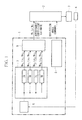
- FIG. 1 is a block diagram schematically showing the configuration of the aerodynamic coefficient estimation device according to the first embodiment.
- An aerodynamic coefficient estimation device 1 is a device that estimates aerodynamic coefficients indicating the aerodynamic characteristics of an aircraft, and is applied to an aircraft as illustrated in FIG. 1 and connected to a flight control system 2 that controls an airframe of the aircraft, control surfaces 3 that generate an aerodynamic force for controlling the attitude of the airframe, and a sensor 4 that detects kinetic state quantities of the airframe.
- the flight control system 2 is a system that performs overall control of the aircraft, and configures a flight control law in accordance with the state of the airframe or of a flight and reconfigures the flight control law based on aerodynamic coefficient estimates estimated by the aerodynamic coefficient estimation device 1. Then, the flight control system 2 outputs a control signal to various types of equipment (not shown) provided on the aircraft in conformity with the flight control law.
- the control surfaces 3 include an elevator that moves the nose of the aircraft up or drown, a rudder that changes the direction that the nose of the aircraft, is pointing to left or right, an aileron that banks the airframe left or right, and a high-lift device (flap) that rectifies the airfoil of a main wing to increase lift.
- An actuator system which is not shown, moves the control surfaces 3 in accordance with a deflection angle command signal, which will be described later, via the flight control system.
- the attitude of the airframe is controlled by an aerodynamic force as a result of the control surfaces 3 being moved.
- the sensor 4 includes various sensors such as an air data sensor, an inertial sensor, and a deflection angle sensor.
- the sensor 4 acquires sensor information related to various kinetic state quantities regarding the kinetic state of the airframe such as the angle of attack, the angle of sideslip, the airspeed, the angular speed, the attitude angle, and the deflection angle of the airframe and outputs the acquired sensor information to a sensor information acquisition unit 6.
- the aerodynamic coefficient estimation device 1 includes a deflection angle command signal generation unit (deflection angle command signal generation means) 5, the sensor information acquisition unit (kinetic state quantity acquisition means) 6, a candidate value calculation unit (candidate value calculation means) 7, and an aerodynamic coefficient estimate determination unit (aerodynamic coefficient estimate determination means) 8.
- the deflection angle command signal generation unit 5 generates a deflection angle command signal that moves the control surfaces 3 so as to impart a certain degree of motion to the airframe in order to estimate the aerodynamic coefficients, and outputs the generated deflection angle command signal to the flight control system 2 in order for the control surfaces 3 to be moved in accordance with the deflection angle command signal.
- the flight control system 2 during a flight of the aircraft, generates a deflection angle command signal for changing or maintaining the airframe to or in a desired attitude, superimposes the deflection angle command signal generated by the deflection angle command signal generation unit 5 on this deflection angle command signal, and outputs the resultant superimposed signal to the actuator system, which is not shown.
- the sensor information acquisition unit 6 acquires, via the sensor 4, kinetic state quantities of the airframe that are obtained as a result of the control surface 3 being moved in accordance with the deflection angle command signal and outputs the acquired kinetic state quantities to the candidate value calculation unit 7, which will be described later.
- the candidate value calculation unit 7 includes a computing device 7A that stores an algorithm based on the extended Kalman filter, a computing device 7B that stores an algorithm based on the unscented Kalman filter, a computing device 7C that stores an algorithm based on the Fourier transform regression technique, and a computing device 7D that stores an algorithm based on the neural network technique, and the computing devices 7A to 7D are adapted to individually calculate a candidate value for estimating the aerodynamic coefficients from the sensor information based on the respective stored algorithms.
- the candidate value calculation unit 7 outputs the candidate values calculated by the computing devices 7A to 7D to the aerodynamic coefficient estimate determination unit 8.
- the candidate value calculation unit 7 may have a configuration in which all of the computing devices 7A to 7D are used to individually compute the candidate values, or may have a configuration in which two or three of the computing devices 7A to 7D are used to individually compute the candidate values. Furthermore, candidate value calculation by the computing devices 7A to 7D is not limited to calculation based the algorithms related to the above-described four estimations, and for example, algorithms related to other estimations such as a particle filter can also be applied.
- the aerodynamic coefficient estimate determination unit 8 determines an aerodynamic coefficient estimate from a plurality of candidate values calculated in the candidate value calculation unit 7. Specifically, an average or a median of the candidate values is computed, and the computed average or median can be finally determined as an aerodynamic coefficient estimate. Beside this, it is possible to compute reproduced values of the sensor information corresponding to the candidate values, respectively, using the candidate values and compare the reproduced values with the sensor information, thereby determining a candidate value corresponding to a reproduced value that matches or is the closest to the sensor information as the aerodynamic coefficient estimate. The determined aerodynamic coefficient estimate is output to the flight control system 2.
- step S11 in FIG. 2 the deflection angle command signal generation unit 5 generates a deflection angle command signal that moves the control surfaces 3 so as to impart a certain degree of motion to the airframe in order to estimate aerodynamic coefficients and outputs the generated deflection angle command signal to the flight control system 2. Then, the process proceeds to the next step S12.
- step S12 the flight control system 2 generates a deflection angle command signal for changing or maintaining the airframe to or in a desired attitude, superimposes the deflection angle command signal that has been generated by the deflection angle command signal generation unit 5 on this deflection angle command signal, and outputs the resultant superimposed deflection angle command signal to the actuator system, which is not shown, and the actuator system moves the control surfaces 3 in accordance with the deflection angle command signal.
- step S13 since the control surfaces 3 have been moved in the previous step S12 and the airframe thus makes a motion such as swaying in accordance with the deflection angle command signal, kinetic state quantities of the airframe that are continuously or periodically acquired by the sensor 4 change.
- the sensor 4 detects the resulting kinetic state quantities as the sensor information and outputs the sensor information to the sensor information acquisition unit 6.
- step S14 the computing devices 7A of 7D of the candidate value calculation unit 7 individually compute candidate values, and the computation results are output to the aerodynamic coefficient estimate determination unit 8.
- step S15 the aerodynamic coefficient estimate determination unit 8 determines the final aerodynamic coefficient estimates based on the candidate values received from the candidate value calculation unit 7 and outputs the determined aerodynamic coefficient estimates to the flight control system 2.
- the flight control system 2 can reconfigure the flight control law in response to the input of the aerodynamic coefficient estimates.
- candidate values for estimating aerodynamic coefficient estimates are calculated based on two or more different estimations, and then, the final aerodynamic coefficient estimates are determined from the candidate values.
- This enables redundancy to be introduced into computation of the aerodynamic coefficient estimates and therefore highly reliable aerodynamic coefficients to be computed.
- the extended Kalman filter, the unscented Kalman filter, the Fourier transform regression technique, and the neural network technique that are applied to the computing devices 7A to 7D do not require angular acceleration of the airframe as the sensor information that is necessary in calculation of the candidate values, there is no need to provide the airframe with a sensor for detecting angular acceleration, and therefore, an increase in the weight of the airframe can be avoided.
- FIG. 3 is a block diagram schematically showing the configuration of the control surface failure/damage detection device according to the second embodiment.
- a control surface failure/damage detection device 11 is a device that detects a failure of or damage to the control surfaces 3 of an aircraft, and detects a failure of a control surface, that is, for example, a situation in which the control surface can no longer respond to the deflection angle command value or can no longer move (is immobilized), or damage to a control surface, that is, for example, a situation in which the control surface is partially or entirely destroyed.
- a failure of or damage to the control surfaces 3 of an aircraft detects a failure of a control surface, that is, for example, a situation in which the control surface can no longer respond to the deflection angle command value or can no longer move (is immobilized), or damage to a control surface, that is, for example, a situation in which the control surface is partially or entirely destroyed.
- the control surface failure/damage detection device 11 includes a failure/damage possibility judging unit 12 and a control surface failure/damage detection unit 15 in addition to an aerodynamic coefficient estimation device 10. Moreover, the control surface failure/damage detection device 11 is applied to the aircraft and connected to the flight control system 2 that controls the airframe of the aircraft, the sensor 4 that detects kinetic state quantities of the airframe, and a display device 16 that is provided in a cockpit or the like of the aircraft.
- the aerodynamic coefficient estimation device 10 included in the control surface failure/damage detection device 11 has the configuration as the aerodynamic coefficient estimation device 1 of the first embodiment, but differs from the aerodynamic coefficient estimation device 1 in that it is provided with a configuration for application to the control surface failure/damage detection device 11.
- a further description of the configuration as the aerodynamic estimation device 1 will be emitted, and the different configuration will be described.
- the deflection angle command signal generation unit 5 generates a deflection angle command signal for aerodynamic coefficient estimation that moves the control surfaces 3 so as to impart a certain degree of motion to the airframe in order to estimate the aerodynamic coefficients, and also generates, based on either aerodynamic coefficients during a normal flight that have been stored in advance or aerodynamic coefficient estimates that were obtained when failure/damage was detected the previous time, a deflection angle command signal (Tkern) for checking failure/damage for moving the control surfaces using a combination of deflection angles that does not impart any motion to the airframe in order to judge the possibility of control surface failure/damage.
- Tkern deflection angle command signal
- the deflection angle command signal generation unit 5 includes an aerodynamic coefficient estimation steering device 5A that generates a deflection angle command signal for aerodynamic coefficient estimation and a failure/damage checking steering device that generates a deflection angle command signal for checking failure/damage.
- the flight control system 2 generates a deflection angle command signal for changing or maintaining the airframe to or in a desired attitude during a flight of the aircraft, superimposes a deflection angle command signal generated by the deflection angle command signal generation unit 5 on this deflection angle command signal, and outputs the resultant superimposed deflection angle command signal to the actuator system.
- the aerodynamic coefficient estimation device 10 includes a changeover switch 13 that is provided in the candidate value calculation unit 7 so that the sensor information is input only if the failure/damage possibility judging unit 12 judges that failure/damage may occur.
- the failure/damage possibility judging unit 12 is connected to the sensor information acquisition unit 6, the deflection angle command signal generation unit 5, and the flight control system 2 and can exchange various types of information with the sensor information acquisition unit 6, the deflection angle signal generation unit 5, and the flight control system 2.
- the failure/damage possibility judging unit 12 also includes a changeover switch 14 at an interface with the deflection angle command signal generation unit 5, and this switch performs switching to allow the failure/damage possibility judging unit 12 to receive a deflection angle command signal from the failure/damage checking steering device 5B when judging the possibility of control surface failure/damage and to receive a deflection angle command signal from the aerodynamic coefficient estimation steering device 5A if it is judged that control surface failure/damage may occur.
- the failure/damage possibility judging unit 12 accepts input of a deflection angle command signal for checking failure/damage that has been output from the failure/damage checking steering device 5B, and outputs the deflection angle command signal for checking failure/damage to the flight control system 2.
- the failure/damage possibility judging unit 12 acquires the sensor information that is obtained as a result of the control surfaces 3 being moved in accordance with this deflection angle command signal for checking failure/damage, from the sensor information acquisition unit 6, and judges whether or not there is a possibility that any of the control surfaces 3 may suffer failure/damage by, for example, comparing the acquired sensor information with a preset threshold.
- the failure/damage possibility judging unit 12 accepts input of a deflection angle command signal for aerodynamic coefficient estimation from the aerodynamic coefficient estimation steering device 5A and outputs the deflection angle command signal for aerodynamic coefficient estimation to the flight control system 2.
- the operation of the changeover switch 13 and the operation of the changeover switch 14 are linked together, and when the changeover switch 14 connects the failure/damage possibility judging unit 12 to the failure/damage checking steering device 5B, the changeover switch 13 is switched off, so that the sensor information is not input to the computing devices 7A to 7D.
- the changeover switch 14 connects the failure/damage possibility judging unit 12 to the aerodynamic coefficient estimation steering device 5A, the switch 13 is switched on, so that the sensor information is input to the computing devices 7A to 7D.
- the control surface failure/damage detection unit 15 receives input of aerodynamic coefficient estimates computed by the aerodynamic coefficient estimation device 10 and detects which control surface suffers the failure/damage based on the aerodynamic coefficient estimates. To detect failure/damage, for example, the control surface failure/damage detection unit 15 stores aerodynamic coefficients during a normal flight of the aircraft in advance and compares these aerodynamic coefficients with the aerodynamic coefficients output from the aerodynamic coefficient estimation device 10. Thus, which control surface suffers the failure/damage can be detected based on the comparison result.
- control surface failure/damage detection result is output to the flight control system 2, the deflection angle command signal generation unit 5, and the display device 16.
- the deflection angle command signal generation unit 5 reflects and then uses the failure/damage portion and the like to generate a deflection angle command signal the next time and thereafter, while the flight control system 2 determines whether or not to use the control surface suffering the failure/damage based on the control surface failure/damage detection result and the aerodynamic coefficient estimates and depending on the extent of the failure of or damage to the control surface, and reconfigures the flight control law. Moreover, since the display device 16 receives the control surface failure/damage detection result, it informs a pilot and the like of which control surface suffers the failure/damage.
- the changeover switch 14 connects the failure/damage checking steering device 5B to the failure/damage possibility judging unit 12, and the possibility of failure/damage is continuously or periodically judged.
- the deflection angle command signal generation unit 5 continuously or periodically generates and outputs a deflection angle command signal (Tkern) for checking failure/damage to the failure/damage possibility judging unit 12.
- the deflection angle command signal for checking failure/damage is output to the flight control system 2 via the failure/damage possibility judging unit 12.
- the deflection angle command signal is superimposed on a deflection angle command signal for changing or maintaining the airframe to or in a desired attitude, which is generated by the flight control system 2, and the control surfaces 3 are moved by the actuator system, which is not shown, based on the resultant superimposed deflection angle command signal.
- step S23 the sensor 4 continuously or periodically acquires kinetic state quantities of the airframe as the sensor information, and the sensor 4 outputs the sensor information to the sensor information acquisition unit 6.
- the sensor information is output from the sensor information acquisition unit 6 to the failure/damage possibility judging unit 12, which judges whether or not there is a possibility that failure/damage may occur in step S24.
- the failure/damage possibility judging unit 12 assumes that even when the control surfaces 3 are moved in accordance with the deflection angle command signal for checking failure/damage, the airframe normally should not make a motion.
- the failure/damage possibility judging unit 12 judges that there is a possibility that control surface failure/damage may occur. Then, the process proceeds to the next step S25. On the other hand, if it can be judged from the sensor information that the airframe does not make a motion such as swaying, the failure/damage possibility judging unit 12 judges that there is no possibility that failure/damage may occur. Judgement in step S24 is periodically repeated.
- step S25 since the failure/damage possibility judging unit 12 has judged that there is a possibility that control surface failure/damage may occur, the changeover switch 13 and the changeover switch 14 are changed in order that the aerodynamic coefficient estimation device 10 estimates the aerodynamic coefficients.
- the failure/damage possibility judging unit 12 is connected to the aerodynamic coefficient estimation steering device 5A, and the sensor information acquisition unit 6 is connected to each of the computing devices 7A to 7B.
- a deflection angle command signal for aerodynamic coefficient estimation is generated by the aerodynamic coefficient estimation steering device 5A and output to the flight control system 2. Then, the process proceeds to the next step S27.
- step S27 the flight control system 2 generates a deflection angle command signal for changing or maintaining the airframe to or in a desired attitude, superimposes the deflection angle command signal generated by the deflection angle command signal generation unit 5 on this deflection angle command signal, and outputs the resultant superimposed deflection angle command signal to the actuator system, and the actuator system moves the control surfaces 3 in accordance with the deflection angle command signal for aerodynamic coefficient estimation.
- step S28 since the control surfaces 3 have been moved in the previous step S27 and the airframe thus makes a motion such as swaying in accordance with the deflection angle command signal, the kinetic state quantities of the airframe that are continuously or periodically acquired by the sensor 4 change.
- the sensor 4 detects the resulting kinetic state quantities as the sensor information and outputs the sensor information to the sensor information acquisition unit 6.
- step S29 the computing devices 7A to 7D of the candidate value calculation unit 7 individually compute candidate values, and the computation results are output to the aerodynamic coefficient estimate determination unit 8.
- the aerodynamic coefficient estimate determination unit 8 determines the final aerodynamic coefficient estimates based on the candidate values input from the candidate value calculation unit 7 and outputs the determined aerodynamic coefficient estimates to the control surface failure/damage detection unit 15, the deflection angle command signal generation unit 5, and the flight control system 2.
- the control surface failure/damage detection unit 15 detects which control surface suffers the failure/damage based on the aerodynamic coefficient estimates. The control surface failure/damage detection result is output to the flight control system 2, the deflection angle command signal generation unit 5, and the display device 16, and the present routine is ended.
- control surface failure/damage the possibility of failure/damage is judged in advance, and if it is judged that there is a possibility that control surface failure/damage may occur, aerodynamic coefficient estimates are calculated, and which control surface suffers the failure/damage is detected based on the aerodynamic coefficient estimates.
- aerodynamic coefficient estimates are calculated, and which control surface suffers the failure/damage is detected based on the aerodynamic coefficient estimates.
- candidate values for estimating the aerodynamic coefficient estimates are calculated based on two or more different estimations by using the computing devices 7A to 7D, and after that, aerodynamic coefficient estimates are finally determined based on the candidate values. This enables redundancy to be introduced into estimation of aerodynamic coefficient estimates and therefore highly reliable aerodynamic coefficients to be computed.
- FIG. 5 is a block diagram schematically showing the configuration of the control surface failure/damage detection device according to the present modification.
- the control surface failure/damage detection device of the present modification differs from the control surface failure/damage detection device according to the second embodiment in that, regardless of whether or not a deflection angle command signal for checking failure/damage has been output, it computes kinetic state quantity predictive values assuming that the airframe is in the normal state and judges the possibility of failure/damage based on the kinetic state quantity predictive values and the actual kinetic state quantities of the airframe.
- control surface failure/damage detection device is therefore not necessarily required to include the failure/damage checking steering device 5B. Since the other configuration is the same as the configuration of the above-described control surface failure/damage detection device, a further description thereof will be omitted, and only the differences will be described bellow.
- the failure/damage possibility judging unit 12 is connected to the sensor information acquisition unit 6, the deflection angle command signal generation unit 5, the aerodynamic coefficient estimate determination unit 8, the flight control system 2, and the control surface failure/damage detection unit 15 and can exchange various types of information with these units.
- the failure/damage possibility judging unit 12 stores an airframe motion model in advance.
- an airframe motion model refers to a mathematical model that can be obtained during design of an aircraft to which the control surface failure/damage detection device can be applied and that expresses motions of the aircraft. When the airframe is in the normal state, the kinetic state quantities of the airframe can be computed from the airframe motion model.
- the failure/damage possibility judging unit 12 continuously or periodically computes kinetic state quantity predictive values representing the kinetic state quantities that are predicted assuming that the airframe is in the normal state, based on the airframe motion model and either a deflection angle command signal for changing or maintaining the airframe to or in a desired attitude during the flight of the aircraft or a superimposed deflection angle command signal obtained by superimposing a deflection angle command signal for checking failure/damage on this deflection angle command signal, which is generated by the flight control system 2.
- the failure/damage possibility judging unit 12 acquires the actual kinetic state quantities of the airframe during the flight based on either the deflection angle command signal for changing or maintaining the airframe attitude during the flight of the aircraft or the superimposed deflection angle command signal obtained by superimposing the deflection angle command signal for checking failure/damage on this deflection angle command signal, which is generated by the flight control system 2, as the sensor information from the sensor information acquisition unit 6.
- the failure/damage possibility judging unit 12 acquires the sensor information that is obtained as a result of the control surfaces 3 being moved in accordance with either the deflection angle command signal for changing or maintaining the attitude of the airframe or the superimposed deflection angle command signal obtained by superimposing the deflection angle command signal for checking failure/damage on this deflection angle command signal, which has been output from the flight control system 2, from the sensor information acquisition unit 6. Then, the failure/damage possibility judging unit 12 compares the computed kinetic state quantity predictive values with the sensor information and judges whether or not there is a possibility that any of the control surfaces 3 may suffer failure/damage based on the difference between the predictive values and the sensor information.
- the failure/damage possibility judging unit 12 accepts input of a deflection angle command signal for aerodynamic coefficient estimation from the aerodynamic coefficient estimation steering device 5A and outputs the deflection angle command signal for aerodynamic coefficient estimation to the flight control system 2. Then, the aerodynamic coefficient estimation device 10 estimates the aerodynamic coefficients, and the control surface failure/damage detection unit 15 detects a failure of or damage to the control surfaces 3.
- the detection result is output to the flight control system 2, the display device 16, the deflection angle command signal generation unit 5, and the failure/damage possibility judging unit 12.
- the deflection angle command signal generation unit 5 and the failure/damage possibility judging unit 12 accumulate the failure/damage detection result and the aerodynamic coefficient estimates in case the failure of or damage to the control surfaces 3 worsens, and reflects the accumulated detection result and aerodynamic coefficient estimates in the next judgement of the possibility of failure/damage. That is to say, the failure/damage detection result and the aerodynamic coefficient estimates that have already been obtained are reflected in computation of kinetic state quantity predictive values based on the airframe motion model, and the resulting predictive values are compared with the actual kinetic state quantities. Thus, if the failure of or damage to the control surfaces 3 worsens, the worsening of the failure or damage could be detected.
- control surface failure/damage is judged based on actual kinetic state quantities during a flight and kinetic state quantity predictive values that are predicted assuming that the airframe is in the normal state.
- a failure of or damage to a control surface can be accurately detected by continuously monitoring control surface failure/damage while minimizing unwanted motion such as unwanted swaying of the airframe and thereby reducing the discomfort for the passengers.
- control surface failure/damage detection device according to another modification of the second embodiment. It should be noted that a schematic configuration of the control surface failure/damage detection device according to this modification is substantially similar to that of the control surface failure/damage detection device according to the above-described modification of the second embodiment shown in FIG. 5 and will therefore be described with reference to FIG. 5 .
- the control surface failure/damage detection device of the present modification differs from the control surface failure/damage detection device according to the second embodiment in the following respects.
- the airframe is provided with an optical fiber or an electric wire, with which a control surface abnormality is detected.
- a deflection angle command signal for checking failure/damage regardless of whether or not a deflection angle command signal for checking failure/damage has been output, either a deflection angle command signal for changing or maintaining the airframe to or in a desired attitude or a superimposed deflection angle command signal obtained by superimposing a deflection angle command signal for checking failure/damage on this deflection angle command signal is generated, and then, an actual deflection angle that is obtained as a result of the control surfaces provided on the airframe being moved based on the generated deflection angle command signal is acquired, and a deflection angle predictive value representing a deflection angle that is predicted based on the deflection angle command signal assuming that the airframe is in the normal state is computed.
- control surface failure/damage detection device of the present modification judges the possibility of control surface damage based on the abnormality detection result obtained from the optical fiber or the like and judges the possibility of control surface failure based on the actual deflection angle and the deflection angle predictive value. Therefore, the control surface failure/damage detection device is not necessarily required to include the failure/damage steering device 5B.
- the other configuration is the same as that of the above-described control surface failure/damage detection device, so a further description thereof will be omitted, and only the differences will be described below.
- An optical fiber or an electric wire for detecting distortion of or damage to an airframe is laid on an outer surface or in an outer layer of the airframe of an aircraft to which the control surface failure/damage detection device of the present modification is applied (not shown). If distortion occurs in the airframe, the transmitted light quantity of the optical fiber or the resistance of the electric wire changes, and if damage occurs to the airframe, light is not transmitted or electrical continuity is broken. For this reason, the optical fiber or the electric wire is connected to a detection sensor that detects an abnormality based on the transmitted light quantity or the resistance.
- the failure/damage possibility judging unit 12 is connected to the sensor information acquisition unit 6, the deflection angle command signal generation unit 5, the aerodynamic coefficient estimate determination unit 8, the flight control system 2, and the control surface failure/damage detection unit 15 and can exchange various types of information with these units.
- the failure/damage possibility judging unit 12 stores a control surface movement model in advance.
- a control surface movement model refers to a mathematical model of a control surface movement system including the actuator system and can be obtained during design of an aircraft to which the control surface failure/damage detection device can be applied, and if the control surfaces are in the normal state, a deflection angle that is obtained as a result of the control surfaces being moved based on a given deflection angle command signal can be computed from the control surface movement model.
- the failure/damage possibility judging unit 12 continuously computes a deflection angle predictive value representing a deflection angle that is predicted assuming that the airframe is in the normal state, from the control surface movement model and either a deflection angle command signal for changing or maintaining the airframe to or in a desired attitude during the flight of the aircraft or a superimposed deflection angle command signal obtained by superimposing a deflection angle command signal for checking failure/damage on this deflection angle command signal.
- the failure/damage possibility judging unit 12 acquires the actual deflection angle of the airframe during the flight based on either the deflection angle command signal for changing or maintaining the airframe attitude during the flight of the aircraft or the superimposed deflection angle command signal obtained by superimposing the deflection angle command signal for checking failure/damage on this deflection angle command signal, as the sensor information from the sensor information acquisition unit 6.
- the failure/damage possibility judging unit 12 accepts the detection result from the detection sensor and judges the possibility of control surface damage. That is to say, if the detection result obtained from the detection sensor is abnormal, it is judged that there is a possibility that control surface damage may occur, and if the detection result is normal, it is judged that there is no possibility that control surface damage may occur.
- the failure/damage possibility judging unit 12 accepts input of either the deflection angle command signal for changing or maintaining the airframe attitude or the superimposed deflection angle command signal obtained by superimposing the deflection angle command signal for checking failure/damage on this deflection angle command signal, which has been output from the flight control system 2, and acquires the deflection angle that is obtained as a result of the control surfaces 3 being moved in accordance with the deflection angle command signal from the sensor information acquisition unit 6. Then, the failure/damage possibility judging unit 12 compares the computed deflection angle predictive value with the deflection angle and judges whether or not there is a possibility that any of the control surfaces 3 may suffer a failure based on the difference between the deflection angle predictive value and the deflection angle.
- the failure/damage possibility judging unit 12 accepts input of a deflection angle command signal for aerodynamic coefficient estimation from the aerodynamic coefficient estimation steering device 5A and outputs the deflection angle command signal for aerodynamic coefficient estimation to the flight control system 2, and then, the aerodynamic coefficient estimation device 10 estimates the aerodynamic coefficients and the control surface failure/damage detection unit 15 detects the failure of or damage to the control surfaces 3.
- the detection result is output to the flight control system 2, the display device 16, the deflection angle command signal generation unit 5, and the failure/damage possibility judging unit 12.
- the deflection angle command signal generation unit 5 and the failure/damage possibility judging unit 12 accumulate the failure/damage detection result and the aerodynamic differential coefficient estimates in case the failure of or the damage to the control surfaces 3 worsens, and the accumulated detection result and estimates are reflected in the next judgement of the possibility of failure/damage.
- control surface damage is judged based on the abnormality detection result obtained from the optical fiber or the electric wire, and the possibility of control surface failure is judged based on the actual deflection angle during flight and the deflection angle predictive value that is predicted assuming that the airframe is in the normal state.
- a failure of or damage to a control surface can be accurately detected by continuously monitoring control surface failure/damage while minimizing unwanted motion such as unwanted swaying of the airframe and thereby reducing the discomfort for the passengers.
- judgement of the possibility based on kinetic state quantities that are obtained as a result of movement in accordance with a deflection angle command signal for checking failure/damage output from the above-described failure/damage checking steering device 5B may also be performed.
- the control surface failure/damage detection device is provided with a failure/damage possibility judgement logic unit 17 including a computing device 17A that stores information related to judgement of the possibility based on the result of comparison between the kinetic state quantity predictive values based on the airframe motion model and the actual kinetic state quantities, a computing device 17B that stores information related to judgement of the possibility based on the abnormality detection result obtained from the optical fiber or the electric wire and the result of comparison between the deflection angle predictive value based on the control surface movement model and the actual deflection angle, and a computing device 17C that stores information related to judgement of the possibility based on the kinetic state quantities that are obtained as a result of movement in accordance with the deflection angle command signal for checking failure/damage.
- a failure/damage possibility judgement logic unit 17 including a computing device 17A that stores information related to judgement of the possibility based on the result of comparison between the kinetic state quantity predictive values based on the airframe motion model and the actual kinetic state quantities, a computing device 17B that stores information related to judgement
- connection between the failure/damage possibility judgement logic unit 17 and the changeover switch 14 is changed so that judgement of the possibility can be performed based on any one of the judgement methods, and thus, judgement of the possibility is performed as desired.
- the connection can be changed successively thereafter so that, for example, judgement of the possibility based on another method can be performed as appropriate to enable judgement of the possibility to be performed based a combination of two or three judgement methods.
Landscapes
- Physics & Mathematics (AREA)
- Engineering & Computer Science (AREA)
- Fluid Mechanics (AREA)
- General Physics & Mathematics (AREA)
- Automation & Control Theory (AREA)
- Aviation & Aerospace Engineering (AREA)
- Control Of Position, Course, Altitude, Or Attitude Of Moving Bodies (AREA)
- Aerodynamic Tests, Hydrodynamic Tests, Wind Tunnels, And Water Tanks (AREA)
- Organic Low-Molecular-Weight Compounds And Preparation Thereof (AREA)
- Testing Of Devices, Machine Parts, Or Other Structures Thereof (AREA)
- Traffic Control Systems (AREA)
Abstract
Description
- The present invention relates to an aerodynamic coefficient estimation device and a control surface failure/damage detection device using the aerodynamic coefficient estimation device, and particularly relates to an aerodynamic coefficient estimation device that estimates aerodynamic coefficients indicating the aerodynamic characteristics of an aircraft and a control surface failure/damage detection device that detects a failure of or damage to control surfaces of the aircraft using the estimated aerodynamic coefficients.
- To estimate aerodynamic coefficients that indicate the aerodynamic characteristics of an aircraft, a method in which information such as the angle of attack, the angle of sideslip, the airspeed, the angular speed, the attitude angle, and the deflection angle is acquired from various sensors provided on the aircraft and computation by an iterative least square technique or a neural network technique is performed based on the acquired information is know. Moreover, a method of detecting a failure of or damage to control surfaces by comparing the thus estimated aerodynamic coefficients with the aerodynamic coefficients of the aircraft in a normal state is known.
For example, Patent Literature 1 (Japanese Unexamined Patent Application, Publication No.2003-175896
Also, a method in which hardware such as an optical fiber or an electric wire is laid on an aircraft to directly detect damage to control surfaces is conceivable. - apanese Unexamined Patent Application, Publication No.
2003-175896 - However, in the case where the aforementioned iterative least square technique is used to estimate aerodynamic coefficients, angular acceleration is needed in order to compute the aerodynamic coefficients. This requires an aircraft to be equipped with a sensor for detecting angular acceleration. The addition of a new sensor will cause the problem of an increase in the weight of the airframe. Moreover, estimating aerodynamic coefficients depending only on a single technique such as the iterative least square technique or the neural network technique will cause a problem in that there is a risk that accurate aerodynamic coefficient estimates cannot be obtained. Thus, when aerodynamic coefficients that have been obtained by the iterative least square technique or the neural network technique are applied to control surface failure/damage detection, erroneous detection may occur, and so there is a problem in that the detection result cannot be easily reflected in a flight control law. Furthermore, the method in which an optical fiber or the like is laid on an airframe has a problem that a failure cannot be detected even though damage can be detected.
- The present invention has been made in order to solve the above-described problems, and it is an object thereof to provide an aerodynamic coefficient estimation device that can compute highly reliable aerodynamic coefficients estimates and to provide a control surface failure/damage detection device that can accurately detect control surface failure/damage by computing highly reliable aerodynamic coefficient estimates while reducing a discomfort for passengers.
- In order to solve the above-described problems, the present invention employs the following solutions.
The present invention provides an aerodynamic coefficient estimation device including a deflection angle command signal generation means that generates a deflection angle command signal for estimating an aerodynamic coefficient indicating an aerodynamic characteristic of an airframe, a kinetic state quantity acquisition means that acquires a kinetic state quantity of the airframe that is obtained as a result of a control surface provided on the airframe being moved based on the deflection angle command signal, a candidate value calculation means that calculates candidate values for estimating the aerodynamic coefficient from the kinetic state quantity using two or more different estimations, and an aerodynamic coefficient estimate determination means that determines an aerodynamic coefficient estimate based on the candidate values. - With the aerodynamic coefficient estimation device of the present invention, the deflection angle command signal generation means generates a deflection angle command signal that moves control surfaces so as to impart a certain degree of motion to the airframe in order to estimate an aerodynamic coefficient, and the control surfaces are moved in accordance with the deflection angle command signal. Subsequently, the kinetic state quantity acquisition means acquires kinetic state quantities such as the angle of attack, the angle of sideslip, the airspeed, the angular speed, the attitude angle, and the deflection angle of the airframe to which the motion has been imparted as a result of the control surfaces being moved, from a sensor or the like provided on the airframe in advance. The candidate value calculation means calculates candidate values serving as candidates for calculating an aerodynamic coefficient estimate based on the kinetic state quantities using two or more different estimations, for example, two or more different estimations selected from an extended Kalman filter, an unscented Kalman filter, a Fourier transform regression technique, a neural network technique, a particle filter, and other techniques. The aerodynamic coefficient estimate determination means finally determines the aerodynamic coefficient estimate by selecting or computing the most appropriate value for the aerodynamic coefficient estimate from these candidate values. In this manner, candidate values for an aerodynamic coefficient estimate are calculated by two or more different estimations, and then the aerodynamic coefficient estimate is finally determined from the candidate values. This enables redundancy to be introduced into computation of the aerodynamic coefficient estimate and therefore a highly reliable aerodynamic coefficient to be computed.
- In an aerodynamic coefficient estimation device according to a first aspect of the present invention, the aerodynamic coefficient estimate determination means determines an average or a median of the candidate values as an aerodynamic coefficient estimate.
With the aerodynamic coefficient estimation device according to the first aspect of the present invention, since an average or a median of the candidate values that have been computed by the different estimations is determined as the aerodynamic coefficient estimate, redundancy can be introduced into computation of the aerodynamic coefficient estimate, and therefore, a highly reliable aerodynamic coefficient can be computed. - In an aerodynamic coefficient estimation device according to a second aspect of the present invention, the aerodynamic coefficient estimate determination means determines a candidate value corresponding to one of the reproduced values of the kinetic state quantity that are computed respectively based on the candidate values as an aerodynamic coefficient estimate, the one reproduced value being the closest to the kinetic state quantity.
- With the aerodynamic coefficient estimation device according to the second aspect of the present invention, a reproduced value of the kinetic state quantity can be computed using each candidate value. Thus, the reproduced values of the kinetic state quantity obtained from the respective candidate values are compared with the actual kinetic state quantity acquired by the kinetic state quantity acquisition means, and the candidate value corresponding to the reproduced value that is the closest to the actual kinetic state quantity is determined as the aerodynamic coefficient estimate. This enables redundancy to be introduced into computation of the aerodynamic coefficient estimate and therefore a highly reliable aerodynamic coefficient to be computed.
- Moreover, a control surface failure/damage detection device of the present invention includes a failure/damage possibility judging that judges the possibility of control surface failure/damage and a control surface failure/damage detection means that detects which control surface suffers a failure or damage based on an aerodynamic coefficient estimate estimated by the aerodynamic coefficient estimation device if the failure/damage possibility judging means judges that there is a possibility that control surface failure/damage may occur.
- With the control surface failure/damage detection device of the present invention, if it is judged that there is a possibility that control surface failure/damage may occur, an aerodynamic coefficient estimate is calculated, and which control surface suffers the failure or damage is detected based on this estimate. Thus, a failure of or damage to a control surface can be accurately detected by continuously monitoring control surface failure/damage while minimizing unwanted motion such as unwanted swaying of the airframe and thereby reducing the discomfort for the passengers.
- In the control surface failure/damage detection device according to a first aspect of the present invention, the failure/damage possibility judging means includes another deflection angle command generation signal that generates a deflection angle command signal for moving the control surface such that the airframe makes no motion and another kinetic state quantity acquisition that acquires a kinetic state quantity of the airframe that is obtained as a result of the control surface provided on the airframe being moved based on the deflection angle command signal, and the possibility of control surface failure/damage is judged based on the kinetic state quantity.
- With the control surface failure/damage detection device according to the first aspect of the present invention, to judge the possibility of control surface failure/damage, the other deflection angle command generation signal generates a deflection angle command signal for controlling the control surfaces using a combination of deflection angles that does not impart any motion to the airframe. The other kinetic state quantity acquisition means acquires a kinetic state quantity of the airframe that is obtained as a result of the control surfaces being moved in accordance with the deflection angle command signal that has been generated in order to judge the possibility of control surface failure/damage. At this time, if it can be judged from the obtained kinetic state quantity that the airframe makes a motion when the airframe normally should not make a motion, the failure/damage possibility judging means judges that there is a possibility that control surface failure/damage may occur based on the kinetic state quantity. As described above, the airframe makes no motion if there is no possibility that control surface failure/damage may occur. Thus, a failure of or damage to a control surface can be accurately detected by continuously or periodically monitoring control surface failure/damage while minimizing unwanted motion such as unwanted swaying of the airframe and thereby reducing the discomfort for the passengers.
- In the control surface failure/damage detection device according to a second aspect of the present invention, the failure/damage possibility judging means includes still another deflection angle command signal generation means that generates a deflection angle command signal for changing or maintaining the airframe to or in a desired attitude, still another kinetic state quantity acquisition means that acquires a kinetic state quantity of the airframe during a flight based on the deflection angle command signal, and a kinetic state quantity prediction means that computes a kinetic state quantity predictive value representing a kinetic state quantity that is predicted assuming that the airframe is in a normal state, and the possibility of control surface failure/damage is judged based on the kinetic state quantity and the kinetic state quantity predictive value.
- With the control surface failure/damage detection device according to the second aspect of the present invention, the possibility of control surface failure/damage is judged based on the actual kinetic state quantity during the flight and the kinetic state quantity predictive value that is predicted assuming that the airframe is in the normal state. Thus, a failure of or damage to a control surface can be accurately detected by continuously monitoring control surface failure/damage while minimizing unwanted motion such as unwanted swaying of the airframe and thereby reducing the discomfort for the passengers.
- A control surface failure/damage detection device according to a third aspect of the present invention includes an optical fiber or an electric wire laid on the airframe and a detection means that detects an abnormality of the optical fiber or the electric wire, wherein the failure/damage possibility judging means includes still another deflection angle command signal generation means that generates a deflection angle command signal for changing or maintaining the airframe to or in a desired attitude, a deflection angle acquisition means that acquires a deflection angle that is obtained as a result of the control surfaces provided on the airframe being moved based on the deflection angle command signal, and a deflection angle prediction means that computes a deflection angle predictive value representing a deflection angle that is predicted based on the deflection angle command signal assuming that the airframe is in a normal state, and the possibility of damage to the control surface is judged based on the detection result of the detection means, and the possibility of a failure of the control surface is judged based on the deflection angle and the deflection angle predictive value.
- With the control surface failure/damage detection device according to the third aspect of the present invention, the possibility of control surface damage is judged based on the abnormality detection result obtained from the optical fiber or the electric wire, and the possibility of control surface failure is judged based on the actual deflection angle during the flight and the deflection angle predictive value that is predicted assuming that the airframe is in the normal state. Thus, a failure of or damage to a control surface can be accurately detected by continuously monitoring control surface failure/damage while minimizing unwanted motion such as unwanted swaying of the airframe and thereby reducing the discomfort for the passengers.
- In a control surface failure/damage detection device according to a fourth aspect of the present invention, the control surface failure/damage detection means detects control surface failure/damage by comparing the aerodynamic coefficient estimate with either an aerodynamic coefficient estimate of the airframe in the normal state or an aerodynamic coefficient estimate that obtained when failure/damage detection performed the previous time.
With the control surface failure/damage detection device according to the fourth aspect of the present invention, the aerodynamic coefficient estimate of the airframe in the normal state and a previously calculated aerodynamic coefficient value are successively stored in advance and are used for comparison during control surface failure/damage detection. Thus, if a failure of or damage to a control surface worsens, the failure of or damage to the control surface could be accurately detected. - As described above, highly reliable aerodynamic coefficient estimates can be computed while reducing the discomfort for the passengers, and the use of the computed aerodynamic coefficient estimates enables accurate detection of control surface failure/damage.
-
-
FIG. 1 is a block diagram schematically showing the configuration of an aerodynamic coefficient estimation device according to a first embodiment of the present invention. -
FIG. 2 is a flowchart illustrating a process for estimating aerodynamic coefficients by the aerodynamic coefficient estimation device according to the first embodiment of the present invention. -
FIG. 3 is a block diagram schematically showing the configuration of a control surface failure/damage detection device according to a second embodiment of the present invention. -
FIG. 4 is flowchart illustrating a process for judging control surface failure/damage by the control surface failure/damage detection device according to the second embodiment of the present invention. -
FIG. 5 is a block diagram schematically showing the configuration of a control surface failure/damage detection device according to a modification of the second embodiment of the present invention. -
FIG. 6 is a block diagram schematically showing the configuration of a control surface failure/damage detection device according to a reference example of the present invention. - Hereinafter, an aerodynamic coefficient estimation device according to a first embodiment of the present invention will be described with reference to the drawings.
FIG. 1 is a block diagram schematically showing the configuration of the aerodynamic coefficient estimation device according to the first embodiment. An aerodynamiccoefficient estimation device 1 is a device that estimates aerodynamic coefficients indicating the aerodynamic characteristics of an aircraft, and is applied to an aircraft as illustrated inFIG. 1 and connected to aflight control system 2 that controls an airframe of the aircraft,control surfaces 3 that generate an aerodynamic force for controlling the attitude of the airframe, and asensor 4 that detects kinetic state quantities of the airframe. - The
flight control system 2 is a system that performs overall control of the aircraft, and configures a flight control law in accordance with the state of the airframe or of a flight and reconfigures the flight control law based on aerodynamic coefficient estimates estimated by the aerodynamiccoefficient estimation device 1. Then, theflight control system 2 outputs a control signal to various types of equipment (not shown) provided on the aircraft in conformity with the flight control law.
Thecontrol surfaces 3 include an elevator that moves the nose of the aircraft up or drown, a rudder that changes the direction that the nose of the aircraft, is pointing to left or right, an aileron that banks the airframe left or right, and a high-lift device (flap) that rectifies the airfoil of a main wing to increase lift. An actuator system, which is not shown, moves thecontrol surfaces 3 in accordance with a deflection angle command signal, which will be described later, via the flight control system. The attitude of the airframe is controlled by an aerodynamic force as a result of thecontrol surfaces 3 being moved.
Thesensor 4 includes various sensors such as an air data sensor, an inertial sensor, and a deflection angle sensor. Thesensor 4 acquires sensor information related to various kinetic state quantities regarding the kinetic state of the airframe such as the angle of attack, the angle of sideslip, the airspeed, the angular speed, the attitude angle, and the deflection angle of the airframe and outputs the acquired sensor information to a sensorinformation acquisition unit 6. - The aerodynamic
coefficient estimation device 1 includes a deflection angle command signal generation unit (deflection angle command signal generation means) 5, the sensor information acquisition unit (kinetic state quantity acquisition means) 6, a candidate value calculation unit (candidate value calculation means) 7, and an aerodynamic coefficient estimate determination unit (aerodynamic coefficient estimate determination means) 8. - The deflection angle command
signal generation unit 5 generates a deflection angle command signal that moves thecontrol surfaces 3 so as to impart a certain degree of motion to the airframe in order to estimate the aerodynamic coefficients, and outputs the generated deflection angle command signal to theflight control system 2 in order for thecontrol surfaces 3 to be moved in accordance with the deflection angle command signal. Moreover, theflight control system 2, during a flight of the aircraft, generates a deflection angle command signal for changing or maintaining the airframe to or in a desired attitude, superimposes the deflection angle command signal generated by the deflection angle commandsignal generation unit 5 on this deflection angle command signal, and outputs the resultant superimposed signal to the actuator system, which is not shown.
The sensorinformation acquisition unit 6 acquires, via thesensor 4, kinetic state quantities of the airframe that are obtained as a result of thecontrol surface 3 being moved in accordance with the deflection angle command signal and outputs the acquired kinetic state quantities to the candidatevalue calculation unit 7, which will be described later. - The candidate
value calculation unit 7 includes acomputing device 7A that stores an algorithm based on the extended Kalman filter, acomputing device 7B that stores an algorithm based on the unscented Kalman filter, acomputing device 7C that stores an algorithm based on the Fourier transform regression technique, and acomputing device 7D that stores an algorithm based on the neural network technique, and thecomputing devices 7A to 7D are adapted to individually calculate a candidate value for estimating the aerodynamic coefficients from the sensor information based on the respective stored algorithms. The candidatevalue calculation unit 7 outputs the candidate values calculated by thecomputing devices 7A to 7D to the aerodynamic coefficientestimate determination unit 8. Here, the candidatevalue calculation unit 7 may have a configuration in which all of thecomputing devices 7A to 7D are used to individually compute the candidate values, or may have a configuration in which two or three of thecomputing devices 7A to 7D are used to individually compute the candidate values. Furthermore, candidate value calculation by thecomputing devices 7A to 7D is not limited to calculation based the algorithms related to the above-described four estimations, and for example, algorithms related to other estimations such as a particle filter can also be applied. - It should be noted that specific operation expressions and the like based on the estimations for calculating candidate values by the
computing devices 7A to 7C have already been made public by the inventor of the present invention at, for example, a symposium held by the Japan Society for Aeronautical and Space Sciences (reference number: JSASS-2009-5057) and are known, and therefore, a further description thereof is not given here. - The aerodynamic coefficient
estimate determination unit 8 determines an aerodynamic coefficient estimate from a plurality of candidate values calculated in the candidatevalue calculation unit 7. Specifically, an average or a median of the candidate values is computed, and the computed average or median can be finally determined as an aerodynamic coefficient estimate. Beside this, it is possible to compute reproduced values of the sensor information corresponding to the candidate values, respectively, using the candidate values and compare the reproduced values with the sensor information, thereby determining a candidate value corresponding to a reproduced value that matches or is the closest to the sensor information as the aerodynamic coefficient estimate. The determined aerodynamic coefficient estimate is output to theflight control system 2. - Hereinafter, a process for calculating aerodynamic coefficient estimates by the aerodynamic
coefficient estimation device 1 having the above-described configuration will be described with reference to a flowchart inFIG. 2 .
In step S11 inFIG. 2 , the deflection angle commandsignal generation unit 5 generates a deflection angle command signal that moves thecontrol surfaces 3 so as to impart a certain degree of motion to the airframe in order to estimate aerodynamic coefficients and outputs the generated deflection angle command signal to theflight control system 2. Then, the process proceeds to the next step S12. In step S12, theflight control system 2 generates a deflection angle command signal for changing or maintaining the airframe to or in a desired attitude, superimposes the deflection angle command signal that has been generated by the deflection angle commandsignal generation unit 5 on this deflection angle command signal, and outputs the resultant superimposed deflection angle command signal to the actuator system, which is not shown, and the actuator system moves thecontrol surfaces 3 in accordance with the deflection angle command signal. - In step S13, since the
control surfaces 3 have been moved in the previous step S12 and the airframe thus makes a motion such as swaying in accordance with the deflection angle command signal, kinetic state quantities of the airframe that are continuously or periodically acquired by thesensor 4 change. Thesensor 4 detects the resulting kinetic state quantities as the sensor information and outputs the sensor information to the sensorinformation acquisition unit 6. - In step S14, the
computing devices 7A of 7D of the candidatevalue calculation unit 7 individually compute candidate values, and the computation results are output to the aerodynamic coefficientestimate determination unit 8. In the subsequent step S15, the aerodynamic coefficientestimate determination unit 8 determines the final aerodynamic coefficient estimates based on the candidate values received from the candidatevalue calculation unit 7 and outputs the determined aerodynamic coefficient estimates to theflight control system 2. Thus, the present routine is ended. Theflight control system 2 can reconfigure the flight control law in response to the input of the aerodynamic coefficient estimates. - In this manner, with the
computing devices 7A to 7D, candidate values for estimating aerodynamic coefficient estimates are calculated based on two or more different estimations, and then, the final aerodynamic coefficient estimates are determined from the candidate values. This enables redundancy to be introduced into computation of the aerodynamic coefficient estimates and therefore highly reliable aerodynamic coefficients to be computed. Moreover, since the extended Kalman filter, the unscented Kalman filter, the Fourier transform regression technique, and the neural network technique that are applied to thecomputing devices 7A to 7D do not require angular acceleration of the airframe as the sensor information that is necessary in calculation of the candidate values, there is no need to provide the airframe with a sensor for detecting angular acceleration, and therefore, an increase in the weight of the airframe can be avoided. - Hereinafter, a control surface failure/damage detection device according to a second embodiment of the present invention will be described with reference to the drawings.
FIG. 3 is a block diagram schematically showing the configuration of the control surface failure/damage detection device according to the second embodiment. A control surface failure/damage detection device 11 is a device that detects a failure of or damage to thecontrol surfaces 3 of an aircraft, and detects a failure of a control surface, that is, for example, a situation in which the control surface can no longer respond to the deflection angle command value or can no longer move (is immobilized), or damage to a control surface, that is, for example, a situation in which the control surface is partially or entirely destroyed. For this purpose, as shown inFIG. 3 , the control surface failure/damage detection device 11 includes a failure/damagepossibility judging unit 12 and a control surface failure/damage detection unit 15 in addition to an aerodynamiccoefficient estimation device 10. Moreover, the control surface failure/damage detection device 11 is applied to the aircraft and connected to theflight control system 2 that controls the airframe of the aircraft, thesensor 4 that detects kinetic state quantities of the airframe, and adisplay device 16 that is provided in a cockpit or the like of the aircraft. - The aerodynamic
coefficient estimation device 10 included in the control surface failure/damage detection device 11 has the configuration as the aerodynamiccoefficient estimation device 1 of the first embodiment, but differs from the aerodynamiccoefficient estimation device 1 in that it is provided with a configuration for application to the control surface failure/damage detection device 11. Hereinafter, a further description of the configuration as theaerodynamic estimation device 1 will be emitted, and the different configuration will be described. - Specifically, the deflection angle command
signal generation unit 5 generates a deflection angle command signal for aerodynamic coefficient estimation that moves thecontrol surfaces 3 so as to impart a certain degree of motion to the airframe in order to estimate the aerodynamic coefficients, and also generates, based on either aerodynamic coefficients during a normal flight that have been stored in advance or aerodynamic coefficient estimates that were obtained when failure/damage was detected the previous time, a deflection angle command signal (Tkern) for checking failure/damage for moving the control surfaces using a combination of deflection angles that does not impart any motion to the airframe in order to judge the possibility of control surface failure/damage. For this purpose, the deflection angle commandsignal generation unit 5 includes an aerodynamic coefficientestimation steering device 5A that generates a deflection angle command signal for aerodynamic coefficient estimation and a failure/damage checking steering device that generates a deflection angle command signal for checking failure/damage. Moreover, theflight control system 2 generates a deflection angle command signal for changing or maintaining the airframe to or in a desired attitude during a flight of the aircraft, superimposes a deflection angle command signal generated by the deflection angle commandsignal generation unit 5 on this deflection angle command signal, and outputs the resultant superimposed deflection angle command signal to the actuator system. - To compute aerodynamic coefficient estimates if the failure/damage
possibility judging unit 12, which will be described later, judges that there is a possibility of failure/damage, the aerodynamiccoefficient estimation device 10 includes achangeover switch 13 that is provided in the candidatevalue calculation unit 7 so that the sensor information is input only if the failure/damagepossibility judging unit 12 judges that failure/damage may occur. - The failure/damage
possibility judging unit 12 is connected to the sensorinformation acquisition unit 6, the deflection angle commandsignal generation unit 5, and theflight control system 2 and can exchange various types of information with the sensorinformation acquisition unit 6, the deflection anglesignal generation unit 5, and theflight control system 2. The failure/damagepossibility judging unit 12 also includes achangeover switch 14 at an interface with the deflection angle commandsignal generation unit 5, and this switch performs switching to allow the failure/damagepossibility judging unit 12 to receive a deflection angle command signal from the failure/damage checkingsteering device 5B when judging the possibility of control surface failure/damage and to receive a deflection angle command signal from the aerodynamic coefficientestimation steering device 5A if it is judged that control surface failure/damage may occur. - To judge the possibility of failure/damage, the failure/damage
possibility judging unit 12 accepts input of a deflection angle command signal for checking failure/damage that has been output from the failure/damage checkingsteering device 5B, and outputs the deflection angle command signal for checking failure/damage to theflight control system 2. The failure/damagepossibility judging unit 12 acquires the sensor information that is obtained as a result of thecontrol surfaces 3 being moved in accordance with this deflection angle command signal for checking failure/damage, from the sensorinformation acquisition unit 6, and judges whether or not there is a possibility that any of thecontrol surfaces 3 may suffer failure/damage by, for example, comparing the acquired sensor information with a preset threshold. If it is judged that there is a possibility that any control surface may suffer failure/damage, the failure/damagepossibility judging unit 12 accepts input of a deflection angle command signal for aerodynamic coefficient estimation from the aerodynamic coefficientestimation steering device 5A and outputs the deflection angle command signal for aerodynamic coefficient estimation to theflight control system 2. - It should be noted that the operation of the
changeover switch 13 and the operation of thechangeover switch 14 are linked together, and when thechangeover switch 14 connects the failure/damagepossibility judging unit 12 to the failure/damage checkingsteering device 5B, thechangeover switch 13 is switched off, so that the sensor information is not input to thecomputing devices 7A to 7D. When thechangeover switch 14 connects the failure/damagepossibility judging unit 12 to the aerodynamic coefficientestimation steering device 5A, theswitch 13 is switched on, so that the sensor information is input to thecomputing devices 7A to 7D. - If it is judged that there is a possibility that any of the
control surfaces 3 may suffer failure/damage, the control surface failure/damage detection unit 15 receives input of aerodynamic coefficient estimates computed by the aerodynamiccoefficient estimation device 10 and detects which control surface suffers the failure/damage based on the aerodynamic coefficient estimates. To detect failure/damage, for example, the control surface failure/damage detection unit 15 stores aerodynamic coefficients during a normal flight of the aircraft in advance and compares these aerodynamic coefficients with the aerodynamic coefficients output from the aerodynamiccoefficient estimation device 10. Thus, which control surface suffers the failure/damage can be detected based on the comparison result. Moreover, for example, if a failure of or damage to the control surface worsens, it is possible to compare the aerodynamic coefficient estimates with aerodynamic coefficient estimates that were obtained when the failure/damage was detected the previous time and detect the failure of or damage to the control surface based on the comparison result. The control surface failure/damage detection result is output to theflight control system 2, the deflection angle commandsignal generation unit 5, and thedisplay device 16. - Once the control surface failure/damage detection result and the aerodynamic coefficient estimates have been input, the deflection angle command
signal generation unit 5 reflects and then uses the failure/damage portion and the like to generate a deflection angle command signal the next time and thereafter, while theflight control system 2 determines whether or not to use the control surface suffering the failure/damage based on the control surface failure/damage detection result and the aerodynamic coefficient estimates and depending on the extent of the failure of or damage to the control surface, and reconfigures the flight control law. Moreover, since thedisplay device 16 receives the control surface failure/damage detection result, it informs a pilot and the like of which control surface suffers the failure/damage. - Hereinafter, a process for judging control surface failure/damage by the thus configured control surface failure/
damage detection device 11 will be described with reference to a flowchart inFIG. 4 .
During a normal flight of the aircraft, thechangeover switch 14 connects the failure/damage checkingsteering device 5B to the failure/damagepossibility judging unit 12, and the possibility of failure/damage is continuously or periodically judged. Thus, in step S21 inFIG. 4 , the deflection angle commandsignal generation unit 5 continuously or periodically generates and outputs a deflection angle command signal (Tkern) for checking failure/damage to the failure/damagepossibility judging unit 12. The deflection angle command signal for checking failure/damage is output to theflight control system 2 via the failure/damagepossibility judging unit 12. In the next step S22, the deflection angle command signal is superimposed on a deflection angle command signal for changing or maintaining the airframe to or in a desired attitude, which is generated by theflight control system 2, and thecontrol surfaces 3 are moved by the actuator system, which is not shown, based on the resultant superimposed deflection angle command signal. - In step S23, the
sensor 4 continuously or periodically acquires kinetic state quantities of the airframe as the sensor information, and thesensor 4 outputs the sensor information to the sensorinformation acquisition unit 6. The sensor information is output from the sensorinformation acquisition unit 6 to the failure/damagepossibility judging unit 12, which judges whether or not there is a possibility that failure/damage may occur in step S24. The failure/damagepossibility judging unit 12 assumes that even when thecontrol surfaces 3 are moved in accordance with the deflection angle command signal for checking failure/damage, the airframe normally should not make a motion. If it can be judged from the sensor information acquired from thesensor 4 that the airframe makes a motion such as swaying, the failure/damagepossibility judging unit 12 judges that there is a possibility that control surface failure/damage may occur. Then, the process proceeds to the next step S25. On the other hand, if it can be judged from the sensor information that the airframe does not make a motion such as swaying, the failure/damagepossibility judging unit 12 judges that there is no possibility that failure/damage may occur. Judgement in step S24 is periodically repeated. - In step S25, since the failure/damage
possibility judging unit 12 has judged that there is a possibility that control surface failure/damage may occur, thechangeover switch 13 and thechangeover switch 14 are changed in order that the aerodynamiccoefficient estimation device 10 estimates the aerodynamic coefficients. As a result, the failure/damagepossibility judging unit 12 is connected to the aerodynamic coefficientestimation steering device 5A, and the sensorinformation acquisition unit 6 is connected to each of thecomputing devices 7A to 7B. In the next step S26, a deflection angle command signal for aerodynamic coefficient estimation is generated by the aerodynamic coefficientestimation steering device 5A and output to theflight control system 2. Then, the process proceeds to the next step S27. In step S27, theflight control system 2 generates a deflection angle command signal for changing or maintaining the airframe to or in a desired attitude, superimposes the deflection angle command signal generated by the deflection angle commandsignal generation unit 5 on this deflection angle command signal, and outputs the resultant superimposed deflection angle command signal to the actuator system, and the actuator system moves thecontrol surfaces 3 in accordance with the deflection angle command signal for aerodynamic coefficient estimation. - In step S28, since the
control surfaces 3 have been moved in the previous step S27 and the airframe thus makes a motion such as swaying in accordance with the deflection angle command signal, the kinetic state quantities of the airframe that are continuously or periodically acquired by thesensor 4 change. Thesensor 4 detects the resulting kinetic state quantities as the sensor information and outputs the sensor information to the sensorinformation acquisition unit 6. - In step S29, the
computing devices 7A to 7D of the candidatevalue calculation unit 7 individually compute candidate values, and the computation results are output to the aerodynamic coefficientestimate determination unit 8. In the next step S30, the aerodynamic coefficientestimate determination unit 8 determines the final aerodynamic coefficient estimates based on the candidate values input from the candidatevalue calculation unit 7 and outputs the determined aerodynamic coefficient estimates to the control surface failure/damage detection unit 15, the deflection angle commandsignal generation unit 5, and theflight control system 2. Furthermore, in step S31, the control surface failure/damage detection unit 15 detects which control surface suffers the failure/damage based on the aerodynamic coefficient estimates. The control surface failure/damage detection result is output to theflight control system 2, the deflection angle commandsignal generation unit 5, and thedisplay device 16, and the present routine is ended. - As described above, to detect control surface failure/damage, the possibility of failure/damage is judged in advance, and if it is judged that there is a possibility that control surface failure/damage may occur, aerodynamic coefficient estimates are calculated, and which control surface suffers the failure/damage is detected based on the aerodynamic coefficient estimates. Thus, a failure of or damage to a control surface can be accurately detected by continuously monitoring control surface failure/damage while minimizing unwanted motion such as unwanted swaying of the airframe and thereby reducing the discomfort for the passengers. To estimate aerodynamic coefficients in order to detect failure/damage, candidate values for estimating the aerodynamic coefficient estimates are calculated based on two or more different estimations by using the
computing devices 7A to 7D, and after that, aerodynamic coefficient estimates are finally determined based on the candidate values. This enables redundancy to be introduced into estimation of aerodynamic coefficient estimates and therefore highly reliable aerodynamic coefficients to be computed. - Hereinafter, a control surface failure/damage detection device according to a modification of the second embodiment will be described with reference to
FIG. 5 .
FIG. 5 is a block diagram schematically showing the configuration of the control surface failure/damage detection device according to the present modification. The control surface failure/damage detection device of the present modification differs from the control surface failure/damage detection device according to the second embodiment in that, regardless of whether or not a deflection angle command signal for checking failure/damage has been output, it computes kinetic state quantity predictive values assuming that the airframe is in the normal state and judges the possibility of failure/damage based on the kinetic state quantity predictive values and the actual kinetic state quantities of the airframe. The control surface failure/damage detection device is therefore not necessarily required to include the failure/damage checkingsteering device 5B. Since the other configuration is the same as the configuration of the above-described control surface failure/damage detection device, a further description thereof will be omitted, and only the differences will be described bellow. - The failure/damage
possibility judging unit 12 is connected to the sensorinformation acquisition unit 6, the deflection angle commandsignal generation unit 5, the aerodynamic coefficientestimate determination unit 8, theflight control system 2, and the control surface failure/damage detection unit 15 and can exchange various types of information with these units. The failure/damagepossibility judging unit 12 stores an airframe motion model in advance. Here, an airframe motion model refers to a mathematical model that can be obtained during design of an aircraft to which the control surface failure/damage detection device can be applied and that expresses motions of the aircraft. When the airframe is in the normal state, the kinetic state quantities of the airframe can be computed from the airframe motion model. For this reason, during a flight of the aircraft, the failure/damagepossibility judging unit 12 continuously or periodically computes kinetic state quantity predictive values representing the kinetic state quantities that are predicted assuming that the airframe is in the normal state, based on the airframe motion model and either a deflection angle command signal for changing or maintaining the airframe to or in a desired attitude during the flight of the aircraft or a superimposed deflection angle command signal obtained by superimposing a deflection angle command signal for checking failure/damage on this deflection angle command signal, which is generated by theflight control system 2. At the same time, the failure/damagepossibility judging unit 12 acquires the actual kinetic state quantities of the airframe during the flight based on either the deflection angle command signal for changing or maintaining the airframe attitude during the flight of the aircraft or the superimposed deflection angle command signal obtained by superimposing the deflection angle command signal for checking failure/damage on this deflection angle command signal, which is generated by theflight control system 2, as the sensor information from the sensorinformation acquisition unit 6. - To judge the possibility of failure/damage, the failure/damage
possibility judging unit 12 acquires the sensor information that is obtained as a result of thecontrol surfaces 3 being moved in accordance with either the deflection angle command signal for changing or maintaining the attitude of the airframe or the superimposed deflection angle command signal obtained by superimposing the deflection angle command signal for checking failure/damage on this deflection angle command signal, which has been output from theflight control system 2, from the sensorinformation acquisition unit 6. Then, the failure/damagepossibility judging unit 12 compares the computed kinetic state quantity predictive values with the sensor information and judges whether or not there is a possibility that any of thecontrol surfaces 3 may suffer failure/damage based on the difference between the predictive values and the sensor information. - That is to say, if the difference exceeds a predetermined threshold, it is judged that there is a possibility that any of the
control surfaces 3 may suffer failure/damage, and if the difference does not exceed the threshold, it is judged that there is no possibility that any of thecontrol surfaces 3 may suffer failure/damage. If it is judged that there is a possibility that control surface failure/damage may occur, the failure/damagepossibility judging unit 12 accepts input of a deflection angle command signal for aerodynamic coefficient estimation from the aerodynamic coefficientestimation steering device 5A and outputs the deflection angle command signal for aerodynamic coefficient estimation to theflight control system 2. Then, the aerodynamiccoefficient estimation device 10 estimates the aerodynamic coefficients, and the control surface failure/damage detection unit 15 detects a failure of or damage to the control surfaces 3. - If it is detected that the
control surfaces 3 suffer a failure or damage, the detection result is output to theflight control system 2, thedisplay device 16, the deflection angle commandsignal generation unit 5, and the failure/damagepossibility judging unit 12. The deflection angle commandsignal generation unit 5 and the failure/damagepossibility judging unit 12 accumulate the failure/damage detection result and the aerodynamic coefficient estimates in case the failure of or damage to thecontrol surfaces 3 worsens, and reflects the accumulated detection result and aerodynamic coefficient estimates in the next judgement of the possibility of failure/damage. That is to say, the failure/damage detection result and the aerodynamic coefficient estimates that have already been obtained are reflected in computation of kinetic state quantity predictive values based on the airframe motion model, and the resulting predictive values are compared with the actual kinetic state quantities. Thus, if the failure of or damage to thecontrol surfaces 3 worsens, the worsening of the failure or damage could be detected. - As described above, the possibility of control surface failure/damage is judged based on actual kinetic state quantities during a flight and kinetic state quantity predictive values that are predicted assuming that the airframe is in the normal state. Thus, a failure of or damage to a control surface can be accurately detected by continuously monitoring control surface failure/damage while minimizing unwanted motion such as unwanted swaying of the airframe and thereby reducing the discomfort for the passengers.
- Hereinafter, a control surface failure/damage detection device according to another modification of the second embodiment will be described. It should be noted that a schematic configuration of the control surface failure/damage detection device according to this modification is substantially similar to that of the control surface failure/damage detection device according to the above-described modification of the second embodiment shown in
FIG. 5 and will therefore be described with reference toFIG. 5 .
The control surface failure/damage detection device of the present modification differs from the control surface failure/damage detection device according to the second embodiment in the following respects. First, the airframe is provided with an optical fiber or an electric wire, with which a control surface abnormality is detected. Second, regardless of whether or not a deflection angle command signal for checking failure/damage has been output, either a deflection angle command signal for changing or maintaining the airframe to or in a desired attitude or a superimposed deflection angle command signal obtained by superimposing a deflection angle command signal for checking failure/damage on this deflection angle command signal is generated, and then, an actual deflection angle that is obtained as a result of the control surfaces provided on the airframe being moved based on the generated deflection angle command signal is acquired, and a deflection angle predictive value representing a deflection angle that is predicted based on the deflection angle command signal assuming that the airframe is in the normal state is computed. Based on these differences, the control surface failure/damage detection device of the present modification judges the possibility of control surface damage based on the abnormality detection result obtained from the optical fiber or the like and judges the possibility of control surface failure based on the actual deflection angle and the deflection angle predictive value. Therefore, the control surface failure/damage detection device is not necessarily required to include the failure/damage steering device 5B. The other configuration is the same as that of the above-described control surface failure/damage detection device, so a further description thereof will be omitted, and only the differences will be described below. - An optical fiber or an electric wire for detecting distortion of or damage to an airframe is laid on an outer surface or in an outer layer of the airframe of an aircraft to which the control surface failure/damage detection device of the present modification is applied (not shown). If distortion occurs in the airframe, the transmitted light quantity of the optical fiber or the resistance of the electric wire changes, and if damage occurs to the airframe, light is not transmitted or electrical continuity is broken. For this reason, the optical fiber or the electric wire is connected to a detection sensor that detects an abnormality based on the transmitted light quantity or the resistance.
- The failure/damage
possibility judging unit 12 is connected to the sensorinformation acquisition unit 6, the deflection angle commandsignal generation unit 5, the aerodynamic coefficientestimate determination unit 8, theflight control system 2, and the control surface failure/damage detection unit 15 and can exchange various types of information with these units. The failure/damagepossibility judging unit 12 stores a control surface movement model in advance. Here, a control surface movement model refers to a mathematical model of a control surface movement system including the actuator system and can be obtained during design of an aircraft to which the control surface failure/damage detection device can be applied, and if the control surfaces are in the normal state, a deflection angle that is obtained as a result of the control surfaces being moved based on a given deflection angle command signal can be computed from the control surface movement model. For this reason, during a flight of the aircraft, the failure/damagepossibility judging unit 12 continuously computes a deflection angle predictive value representing a deflection angle that is predicted assuming that the airframe is in the normal state, from the control surface movement model and either a deflection angle command signal for changing or maintaining the airframe to or in a desired attitude during the flight of the aircraft or a superimposed deflection angle command signal obtained by superimposing a deflection angle command signal for checking failure/damage on this deflection angle command signal. At the same time, the failure/damagepossibility judging unit 12 acquires the actual deflection angle of the airframe during the flight based on either the deflection angle command signal for changing or maintaining the airframe attitude during the flight of the aircraft or the superimposed deflection angle command signal obtained by superimposing the deflection angle command signal for checking failure/damage on this deflection angle command signal, as the sensor information from the sensorinformation acquisition unit 6. - When judging the possibility of failure/damage, the failure/damage
possibility judging unit 12 accepts the detection result from the detection sensor and judges the possibility of control surface damage. That is to say, if the detection result obtained from the detection sensor is abnormal, it is judged that there is a possibility that control surface damage may occur, and if the detection result is normal, it is judged that there is no possibility that control surface damage may occur. - Moreover, the failure/damage
possibility judging unit 12 accepts input of either the deflection angle command signal for changing or maintaining the airframe attitude or the superimposed deflection angle command signal obtained by superimposing the deflection angle command signal for checking failure/damage on this deflection angle command signal, which has been output from theflight control system 2, and acquires the deflection angle that is obtained as a result of thecontrol surfaces 3 being moved in accordance with the deflection angle command signal from the sensorinformation acquisition unit 6. Then, the failure/damagepossibility judging unit 12 compares the computed deflection angle predictive value with the deflection angle and judges whether or not there is a possibility that any of thecontrol surfaces 3 may suffer a failure based on the difference between the deflection angle predictive value and the deflection angle.
That is to say, if the difference exceeds a predetermined threshold, it is judged that there is a possibility that any of thecontrol surfaces 3 may suffer a failure, and if the difference does not exceed the threshold, it is judged that there is no possibility that any of thecontrol surfaces 3 may suffer a failure. - If it is judged that there is a possibility that the
control surfaces 3 may suffer failure/damage, the failure/damagepossibility judging unit 12 accepts input of a deflection angle command signal for aerodynamic coefficient estimation from the aerodynamic coefficientestimation steering device 5A and outputs the deflection angle command signal for aerodynamic coefficient estimation to theflight control system 2, and then, the aerodynamiccoefficient estimation device 10 estimates the aerodynamic coefficients and the control surface failure/damage detection unit 15 detects the failure of or damage to the control surfaces 3. - If it is detected that the
control surfaces 3 suffer a failure or damage, the detection result is output to theflight control system 2, thedisplay device 16, the deflection angle commandsignal generation unit 5, and the failure/damagepossibility judging unit 12. The deflection angle commandsignal generation unit 5 and the failure/damagepossibility judging unit 12 accumulate the failure/damage detection result and the aerodynamic differential coefficient estimates in case the failure of or the damage to thecontrol surfaces 3 worsens, and the accumulated detection result and estimates are reflected in the next judgement of the possibility of failure/damage. - As described above, the possibility of control surface damage is judged based on the abnormality detection result obtained from the optical fiber or the electric wire, and the possibility of control surface failure is judged based on the actual deflection angle during flight and the deflection angle predictive value that is predicted assuming that the airframe is in the normal state. Thus, a failure of or damage to a control surface can be accurately detected by continuously monitoring control surface failure/damage while minimizing unwanted motion such as unwanted swaying of the airframe and thereby reducing the discomfort for the passengers.
- It should be noted that to judge the possibility of failure/damage, in addition to judgement of the possibility based on the result of comparison between the kinetic state quantity predictive values based on the airframe motion model and the actual kinetic state quantities and judgement of the possibility based on the abnormality detection result obtained from the optical fiber or the electric wire and the result of comparison between the deflection angle predictive value based on the control surface movement model and the actual deflection angle, judgement of the possibility based on kinetic state quantities that are obtained as a result of movement in accordance with a deflection angle command signal for checking failure/damage output from the above-described failure/damage checking
steering device 5B may also be performed. - This can be realized by, for example, providing a control surface failure/damage detection device with a configuration as shown in
FIG. 6 . Specifically, the control surface failure/damage detection device is provided with a failure/damage possibilityjudgement logic unit 17 including acomputing device 17A that stores information related to judgement of the possibility based on the result of comparison between the kinetic state quantity predictive values based on the airframe motion model and the actual kinetic state quantities, acomputing device 17B that stores information related to judgement of the possibility based on the abnormality detection result obtained from the optical fiber or the electric wire and the result of comparison between the deflection angle predictive value based on the control surface movement model and the actual deflection angle, and acomputing device 17C that stores information related to judgement of the possibility based on the kinetic state quantities that are obtained as a result of movement in accordance with the deflection angle command signal for checking failure/damage. Then, the connection between the failure/damage possibilityjudgement logic unit 17 and thechangeover switch 14 is changed so that judgement of the possibility can be performed based on any one of the judgement methods, and thus, judgement of the possibility is performed as desired. The connection can be changed successively thereafter so that, for example, judgement of the possibility based on another method can be performed as appropriate to enable judgement of the possibility to be performed based a combination of two or three judgement methods. -
- 1 Aerodynamic coefficient estimation device
- 2 Flight control system
- 3 Control surface
- 4 Sensor
- 5 Deflection angle command signal generation unit (deflection angle command signal generation means)
- 6 Sensor information acquisition unit (kinetic state quantity acquisition unit)
- 7 Candidate value calculation unit (candidate value calculation means)
- 8 Aerodynamic coefficient estimate determination unit (aerodynamic coefficient estimate determination means)
- 10 Aerodynamic coefficient estimation device
- 11 Control surface failure/damage detection device
- 12 Failure/damage possibility judging unit (failure/damage possibility judging means)
- 13 Changeover switch
- 14 Changeover switch
- 15 Control surface failure/damage detection unit (control surface failure/damage detection means)
- 16 Display device
- 17 Failure/damage possibility judgement logic unit
- 17A, 17B, and 17C Computing device
Claims (8)
- An aerodynamic coefficient estimation device comprising:a deflection angle command signal generation means that generates a deflection angle command signal for estimating an aerodynamic coefficient indicating an aerodynamic characteristic of an airframe;a kinetic state quantity acquisition means that acquires a kinetic state quantity of the airframe that is obtained as a result of a control surface provided on the airframe being moved based on the deflection angle command signal;a candidate value calculation means that calculates candidate values for estimating the aerodynamic coefficient from the kinetic state quantity using two or more different estimations; andan aerodynamic coefficient estimate determination means that determines an aerodynamic coefficient estimate based on the candidate values.
- The aerodynamic coefficient estimation device according to claim 1, wherein the aerodynamic coefficient estimate determination means determines an average or a median of the candidate values as an aerodynamic coefficient estimate.
- The aerodynamic coefficient estimation device according to claim 1, wherein the aerodynamic coefficient estimate determination means determines a candidate value corresponding to one of reproduced values of the kinetic state quantity that are computed respectively based on the candidate values as an aerodynamic coefficient estimate, the one reproduced value being the closest to the kinetic state quantity.
- A control surface failure/damage detection device comprising:a failure/damage possibility judging means that judges the possibility of control surface failure/damage;the aerodynamic coefficient estimation device according to any one of claims 1 to 3; anda control surface failure/damage detection means that detects which control surface suffers a failure or damage based on an aerodynamic coefficient estimate estimated by the aerodynamic coefficient estimation device if the failure/damage possibility judging means judges that there is a possibility that control surface failure/damage may occur.
- The control surface failure/damage detection device according to claim 4,
wherein the failure/damage possibility judging means includes:another deflection angle command generation signal that generates a deflection angle command signal for moving the control surface such that the airframe makes no motion; andanother kinetic state quantity acquisition means that acquires a kinetic state quantity of the airframe that is obtained as a result of the control surface provided on the airframe being moved based on the deflection angle command signal, andthe possibility of control surface failure/damage is judged based on the kinetic state quantity. - The control surface failure/damage detection device according to claim 4,
wherein the failure/damage possibility judging means includes:still another deflection angle command signal generation means that generates a deflection angle command signal for changing or maintaining the airframe to or in a desired attitude;still another kinetic state quantity acquisition means that acquires a kinetic state quantity of the airframe during a flight based on the deflection angle command signal; anda kinetic state quantity prediction means that computes a kinetic state quantity predictive value representing a kinetic state quantity that is predicted assuming that the airframe is in a normal state, andthe possibility of control surface failure/damage is judged based on the kinetic state quantity and the kinetic state quantity predictive value. - The control surface failure/damage detection device according to claim 4, comprising:an optical fiber or an electric wire laid on the airframe; anda detection means that detects an abnormality of the optical fiber or the electric wire,wherein the failure/damage possibility judging means includes:still another deflection angle command signal generation means that generates a deflection angle command signal for changing or maintaining the airframe to or in a desired attitude;a deflection angle acquisition means that acquires a deflection angle that is obtained as a result of the control surface provided on the airframe being moved based on the deflection angle command signal; anda deflection angle prediction means that computes a deflection angle predictive value representing a deflection angle that is predicted based on the deflection angle command signal assuming that the airframe is in a normal state, andthe possibility of damage to the control surface is judged based on the detection result of the detection means, and the possibility of a failure of the control surface is judged based on the deflection angle and the deflection angle predictive value.
- The control surface failure/damage detection device according to any one of claims 4 to 7,
wherein the control surface failure/damage detection means detects a failure of or damage to the control surface by comparing the aerodynamic coefficient estimate with either an aerodynamic coefficient estimate of the airframe in a normal state or an aerodynamic coefficient estimate that was obtained when failure/damage detection was performed the previous time.
Applications Claiming Priority (2)
| Application Number | Priority Date | Filing Date | Title |
|---|---|---|---|
| JP2010062708A JP5550398B2 (en) | 2010-03-18 | 2010-03-18 | Control surface failure / damage detection device |
| PCT/JP2011/056191 WO2011115164A1 (en) | 2010-03-18 | 2011-03-16 | Aerodynamic coefficient estimation device and control surface failure/damage detection device |
Publications (3)
| Publication Number | Publication Date |
|---|---|
| EP2548799A1 true EP2548799A1 (en) | 2013-01-23 |
| EP2548799A4 EP2548799A4 (en) | 2017-10-11 |
| EP2548799B1 EP2548799B1 (en) | 2019-08-14 |
Family
ID=44649247
Family Applications (1)
| Application Number | Title | Priority Date | Filing Date |
|---|---|---|---|
| EP11756348.6A Active EP2548799B1 (en) | 2010-03-18 | 2011-03-16 | Aerodynamic coefficient estimation device and control surface failure/damage detection device |
Country Status (8)
| Country | Link |
|---|---|
| US (1) | US8954208B2 (en) |
| EP (1) | EP2548799B1 (en) |
| JP (1) | JP5550398B2 (en) |
| CN (1) | CN102753435B (en) |
| BR (1) | BR112012020284A2 (en) |
| CA (1) | CA2788536C (en) |
| RU (1) | RU2515947C1 (en) |
| WO (1) | WO2011115164A1 (en) |
Families Citing this family (26)
| Publication number | Priority date | Publication date | Assignee | Title |
|---|---|---|---|---|
| JPH0687533B2 (en) | 1988-08-15 | 1994-11-02 | 株式会社村田製作所 | Piezoelectric resonance device |
| FR2966951A1 (en) * | 2010-11-03 | 2012-05-04 | Airbus Operations Sas | SIMULATION METHOD FOR DETERMINING AERODYNAMIC COEFFICIENTS OF AN AIRCRAFT |
| FR2978858B1 (en) * | 2011-08-01 | 2013-08-30 | Airbus Operations Sas | METHOD AND SYSTEM FOR DETERMINING FLIGHT PARAMETERS OF AN AIRCRAFT |
| JP5811711B2 (en) | 2011-09-07 | 2015-11-11 | 株式会社リコー | Device linkage system, function provision method |
| PL2700814T3 (en) * | 2012-08-23 | 2015-07-31 | Ampyx Power B V | Glider for airborne wind energy production |
| FR3010448B1 (en) * | 2013-09-06 | 2015-08-21 | Snecma | METHOD FOR MONITORING A DEGRADATION OF AN AIRCRAFT DEVICE OF AN AIRCRAFT WITH AUTOMATIC DETERMINATION OF A DECISION THRESHOLD |
| US9180962B2 (en) | 2013-09-24 | 2015-11-10 | The Boeing Company | Leading edge variable camber system and method |
| US9254909B2 (en) | 2013-09-24 | 2016-02-09 | The Boeing Company | Optimized flap positioning for go-around operations |
| US9327827B2 (en) | 2013-09-24 | 2016-05-03 | The Boeing Company | Leading and trailing edge device deflections during descent of an aircraft |
| US9656741B2 (en) * | 2013-09-24 | 2017-05-23 | The Boeing Company | Control interface for leading and trailing edge devices |
| US9359065B2 (en) | 2013-09-24 | 2016-06-07 | The Boeing Company | System and method for optimizing performance of an aircraft |
| US9284043B2 (en) * | 2013-11-21 | 2016-03-15 | Aai Corporation | Evaluating aileron deflection while an unmanned aerial vehicle is in flight |
| US10401875B2 (en) | 2014-07-31 | 2019-09-03 | The Boeing Company | Electronic stopper in actuator control |
| US9418561B2 (en) * | 2014-12-02 | 2016-08-16 | Honeywell International Inc. | System and method for displaying predictive conformal configuration cues for executing a landing |
| US10043402B1 (en) * | 2015-09-04 | 2018-08-07 | Rockwell Collins, Inc. | Flight path cross check |
| US9701418B2 (en) | 2015-10-06 | 2017-07-11 | Honeywell International Inc. | Pilot fatigue detection system and method from aircraft control device movement |
| WO2018055827A1 (en) | 2016-09-26 | 2018-03-29 | 株式会社Subaru | Damage detection system and damage detection method |
| FR3057954B1 (en) * | 2016-10-24 | 2021-04-02 | Safran Landing Systems | METHOD OF ESTIMATING THE DAMAGE SUFFERED BY PARTS OF AIRCRAFT LANDING GEAR |
| CN107483230B (en) * | 2017-07-26 | 2020-11-03 | 中国航空工业集团公司西安飞机设计研究所 | Ground detection method for airplane wheel-borne signals |
| CA3002186A1 (en) * | 2018-04-19 | 2019-10-19 | Motus Design Group Ltd. | Aerodynamic drag monitoring system and method |
| CN109387350B (en) * | 2018-12-06 | 2023-08-25 | 中国航空工业集团公司沈阳空气动力研究所 | Internal coaxial corrugated pipe balance system |
| GB2593196A (en) * | 2020-03-19 | 2021-09-22 | Airbus Operations Ltd | Aircraft fuel system monitoring |
| CN112478197B (en) * | 2020-12-07 | 2024-09-20 | 中国民用航空上海航空器适航审定中心 | Method for dynamically measuring gap of control surface of airplane |
| US11905840B2 (en) * | 2021-02-01 | 2024-02-20 | Pratt & Whitney Canada Corp. | System and method for detecting failure of a propeller feedback device |
| CN114608794B (en) * | 2022-05-11 | 2022-07-19 | 中国航空工业集团公司哈尔滨空气动力研究所 | Method for measuring aerodynamic coefficient of model wind tunnel virtual flight test |
| KR102855608B1 (en) * | 2023-06-26 | 2025-09-05 | 건국대학교 산학협력단 | Estimation and separation method of dynamic stability derivatives of urban air mobility aircraft |
Family Cites Families (12)
| Publication number | Priority date | Publication date | Assignee | Title |
|---|---|---|---|---|
| US3691356A (en) * | 1970-12-10 | 1972-09-12 | Sperry Rand Corp | Speed command and throttle control system for aircraft |
| JPH06336199A (en) * | 1993-05-28 | 1994-12-06 | Mitsubishi Heavy Ind Ltd | Member damage detecting device for aircraft |
| FR2739683B1 (en) * | 1995-10-05 | 1997-12-05 | France Etat | LABEL TYPE KINETIC ENERGY EXERCISE PROJECTILE |
| JPH10167194A (en) * | 1996-12-12 | 1998-06-23 | Mitsubishi Heavy Ind Ltd | Flight control device having control surface damage detection function |
| US6246929B1 (en) * | 1999-06-16 | 2001-06-12 | Lockheed Martin Corporation | Enhanced stall and recovery control system |
| JP2003175896A (en) * | 2001-12-10 | 2003-06-24 | Mitsubishi Heavy Ind Ltd | Failure and damage detecting apparatus for rudder surface |
| JP3637326B2 (en) * | 2002-04-03 | 2005-04-13 | 三菱重工業株式会社 | Control system, flight control system for aircraft / spacecraft, vehicle motion control system |
| JP5128766B2 (en) * | 2005-11-08 | 2013-01-23 | 東洋電装株式会社 | Rudder angle sensor |
| DE102005058192A1 (en) | 2005-12-06 | 2007-06-28 | Airbus Deutschland Gmbh | Device for fault detection of adjustable flaps |
| FR2908107B1 (en) * | 2006-11-06 | 2008-12-19 | Airbus France Sa | METHOD AND DEVICE FOR ESTIMATING THE FORCES EXERCISING ON A CONTROL SURFACE OF AN AIRCRAFT. |
| FR2916868B1 (en) * | 2007-06-01 | 2009-07-24 | Airbus France Sas | METHOD AND DEVICE FOR DETERMINING THE DYNAMIC STABILITY MARGIN OF AN AIRCRAFT |
| US8380473B2 (en) * | 2009-06-13 | 2013-02-19 | Eric T. Falangas | Method of modeling dynamic characteristics of a flight vehicle |
-
2010
- 2010-03-18 JP JP2010062708A patent/JP5550398B2/en active Active
-
2011
- 2011-03-16 BR BR112012020284A patent/BR112012020284A2/en not_active Application Discontinuation
- 2011-03-16 WO PCT/JP2011/056191 patent/WO2011115164A1/en not_active Ceased
- 2011-03-16 CN CN201180008999.9A patent/CN102753435B/en not_active Expired - Fee Related
- 2011-03-16 US US13/575,365 patent/US8954208B2/en active Active
- 2011-03-16 RU RU2012131672/11A patent/RU2515947C1/en active
- 2011-03-16 EP EP11756348.6A patent/EP2548799B1/en active Active
- 2011-03-16 CA CA2788536A patent/CA2788536C/en not_active Expired - Fee Related
Non-Patent Citations (1)
| Title |
|---|
| See references of WO2011115164A1 * |
Also Published As
| Publication number | Publication date |
|---|---|
| RU2012131672A (en) | 2014-04-27 |
| CA2788536A1 (en) | 2011-09-22 |
| CA2788536C (en) | 2016-06-21 |
| JP5550398B2 (en) | 2014-07-16 |
| US20120296500A1 (en) | 2012-11-22 |
| EP2548799B1 (en) | 2019-08-14 |
| WO2011115164A1 (en) | 2011-09-22 |
| RU2515947C1 (en) | 2014-05-20 |
| CN102753435A (en) | 2012-10-24 |
| US8954208B2 (en) | 2015-02-10 |
| EP2548799A4 (en) | 2017-10-11 |
| CN102753435B (en) | 2016-05-04 |
| BR112012020284A2 (en) | 2016-05-03 |
| JP2011194974A (en) | 2011-10-06 |
Similar Documents
| Publication | Publication Date | Title |
|---|---|---|
| CA2788536C (en) | Aerodynamic coefficient estimation device and control surface failure/damage detection device | |
| JP5982213B2 (en) | Method and system for determining flight parameters of an aircraft | |
| KR101021801B1 (en) | Control Plane Driver Failure Diagnosis of Unmanned Aerial Vehicle Using Adaptive Unknown Input Observer | |
| CN108693793B (en) | Aircraft flight control system and aircraft | |
| RU2561168C2 (en) | Aeroplane control system, aeroplane and aeroplane control method | |
| EP4053020A1 (en) | Autonomous maneuver generation to mate connectors | |
| CN113247302B (en) | Methods and systems for monitoring the condition of VTOL aircraft | |
| CN108732919B (en) | Flight control computer for aircraft | |
| CN106335645A (en) | Health Monitoring of an Actuator in a Flying Device | |
| CN104950740A (en) | System for vehicles with redundant computers | |
| WO2019142563A1 (en) | Electronic control device | |
| IL269350A (en) | Aircraft flight envelope protection and recovery autopilot | |
| US20120053762A1 (en) | Inceptor system and apparatus for generating a virtual real-time model | |
| CA2848110A1 (en) | Methods for predicting a speed brake system fault | |
| CN110780677A (en) | System and method for monitoring the status of an unmanned aerial vehicle | |
| EP3521175A1 (en) | Methods and systems for controlling thrust produced by a plurality of engines on an aircraft for assisting with certain flight conditions | |
| WO2016137566A1 (en) | Tip clearance harmonic estimation | |
| CN110709709B (en) | Method and system for determining an estimate of a speed measurement parameter of an aircraft | |
| Caliskan et al. | Aircraft icing detection, identification, and reconfigurable control based on Kalman filtering and neural networks | |
| EP3885255B1 (en) | Control system | |
| US20150360767A1 (en) | Method and device for generating at least one set point from a flight control set point, a motor control set point and an aircraft guidance set point, related computer program product and aircraft | |
| RU2629454C2 (en) | Method for forming fault-tolerant integrated control system (ics) and fault-tolerant ics | |
| KR20240095551A (en) | Method and apparatus for sensor fault detection and flight recovery of a multicopter | |
| EP3683641A1 (en) | Methods for determining usage in fly-by-wire systems | |
| JP5933350B2 (en) | Guidance device |
Legal Events
| Date | Code | Title | Description |
|---|---|---|---|
| PUAI | Public reference made under article 153(3) epc to a published international application that has entered the european phase |
Free format text: ORIGINAL CODE: 0009012 |
|
| 17P | Request for examination filed |
Effective date: 20120730 |
|
| AK | Designated contracting states |
Kind code of ref document: A1 Designated state(s): AL AT BE BG CH CY CZ DE DK EE ES FI FR GB GR HR HU IE IS IT LI LT LU LV MC MK MT NL NO PL PT RO RS SE SI SK SM TR |
|
| DAX | Request for extension of the european patent (deleted) | ||
| RA4 | Supplementary search report drawn up and despatched (corrected) |
Effective date: 20170911 |
|
| RIC1 | Information provided on ipc code assigned before grant |
Ipc: B64C 13/00 20060101AFI20170905BHEP Ipc: G01M 9/06 20060101ALI20170905BHEP |
|
| GRAP | Despatch of communication of intention to grant a patent |
Free format text: ORIGINAL CODE: EPIDOSNIGR1 |
|
| STAA | Information on the status of an ep patent application or granted ep patent |
Free format text: STATUS: GRANT OF PATENT IS INTENDED |
|
| INTG | Intention to grant announced |
Effective date: 20190415 |
|
| GRAS | Grant fee paid |
Free format text: ORIGINAL CODE: EPIDOSNIGR3 |
|
| GRAA | (expected) grant |
Free format text: ORIGINAL CODE: 0009210 |
|
| STAA | Information on the status of an ep patent application or granted ep patent |
Free format text: STATUS: THE PATENT HAS BEEN GRANTED |
|
| AK | Designated contracting states |
Kind code of ref document: B1 Designated state(s): AL AT BE BG CH CY CZ DE DK EE ES FI FR GB GR HR HU IE IS IT LI LT LU LV MC MK MT NL NO PL PT RO RS SE SI SK SM TR |
|
| REG | Reference to a national code |
Ref country code: GB Ref legal event code: FG4D |
|
| REG | Reference to a national code |
Ref country code: CH Ref legal event code: EP Ref country code: AT Ref legal event code: REF Ref document number: 1166724 Country of ref document: AT Kind code of ref document: T Effective date: 20190815 |
|
| REG | Reference to a national code |
Ref country code: IE Ref legal event code: FG4D |
|
| REG | Reference to a national code |
Ref country code: DE Ref legal event code: R096 Ref document number: 602011061267 Country of ref document: DE |
|
| REG | Reference to a national code |
Ref country code: NL Ref legal event code: MP Effective date: 20190814 |
|
| REG | Reference to a national code |
Ref country code: LT Ref legal event code: MG4D |
|
| PG25 | Lapsed in a contracting state [announced via postgrant information from national office to epo] |
Ref country code: FI Free format text: LAPSE BECAUSE OF FAILURE TO SUBMIT A TRANSLATION OF THE DESCRIPTION OR TO PAY THE FEE WITHIN THE PRESCRIBED TIME-LIMIT Effective date: 20190814 Ref country code: NO Free format text: LAPSE BECAUSE OF FAILURE TO SUBMIT A TRANSLATION OF THE DESCRIPTION OR TO PAY THE FEE WITHIN THE PRESCRIBED TIME-LIMIT Effective date: 20191114 Ref country code: SE Free format text: LAPSE BECAUSE OF FAILURE TO SUBMIT A TRANSLATION OF THE DESCRIPTION OR TO PAY THE FEE WITHIN THE PRESCRIBED TIME-LIMIT Effective date: 20190814 Ref country code: NL Free format text: LAPSE BECAUSE OF FAILURE TO SUBMIT A TRANSLATION OF THE DESCRIPTION OR TO PAY THE FEE WITHIN THE PRESCRIBED TIME-LIMIT Effective date: 20190814 Ref country code: BG Free format text: LAPSE BECAUSE OF FAILURE TO SUBMIT A TRANSLATION OF THE DESCRIPTION OR TO PAY THE FEE WITHIN THE PRESCRIBED TIME-LIMIT Effective date: 20191114 Ref country code: PT Free format text: LAPSE BECAUSE OF FAILURE TO SUBMIT A TRANSLATION OF THE DESCRIPTION OR TO PAY THE FEE WITHIN THE PRESCRIBED TIME-LIMIT Effective date: 20191216 Ref country code: LT Free format text: LAPSE BECAUSE OF FAILURE TO SUBMIT A TRANSLATION OF THE DESCRIPTION OR TO PAY THE FEE WITHIN THE PRESCRIBED TIME-LIMIT Effective date: 20190814 Ref country code: HR Free format text: LAPSE BECAUSE OF FAILURE TO SUBMIT A TRANSLATION OF THE DESCRIPTION OR TO PAY THE FEE WITHIN THE PRESCRIBED TIME-LIMIT Effective date: 20190814 |
|
| REG | Reference to a national code |
Ref country code: AT Ref legal event code: MK05 Ref document number: 1166724 Country of ref document: AT Kind code of ref document: T Effective date: 20190814 |
|
| PG25 | Lapsed in a contracting state [announced via postgrant information from national office to epo] |
Ref country code: RS Free format text: LAPSE BECAUSE OF FAILURE TO SUBMIT A TRANSLATION OF THE DESCRIPTION OR TO PAY THE FEE WITHIN THE PRESCRIBED TIME-LIMIT Effective date: 20190814 Ref country code: AL Free format text: LAPSE BECAUSE OF FAILURE TO SUBMIT A TRANSLATION OF THE DESCRIPTION OR TO PAY THE FEE WITHIN THE PRESCRIBED TIME-LIMIT Effective date: 20190814 Ref country code: LV Free format text: LAPSE BECAUSE OF FAILURE TO SUBMIT A TRANSLATION OF THE DESCRIPTION OR TO PAY THE FEE WITHIN THE PRESCRIBED TIME-LIMIT Effective date: 20190814 Ref country code: GR Free format text: LAPSE BECAUSE OF FAILURE TO SUBMIT A TRANSLATION OF THE DESCRIPTION OR TO PAY THE FEE WITHIN THE PRESCRIBED TIME-LIMIT Effective date: 20191115 Ref country code: IS Free format text: LAPSE BECAUSE OF FAILURE TO SUBMIT A TRANSLATION OF THE DESCRIPTION OR TO PAY THE FEE WITHIN THE PRESCRIBED TIME-LIMIT Effective date: 20191214 Ref country code: ES Free format text: LAPSE BECAUSE OF FAILURE TO SUBMIT A TRANSLATION OF THE DESCRIPTION OR TO PAY THE FEE WITHIN THE PRESCRIBED TIME-LIMIT Effective date: 20190814 |
|
| PG25 | Lapsed in a contracting state [announced via postgrant information from national office to epo] |
Ref country code: TR Free format text: LAPSE BECAUSE OF FAILURE TO SUBMIT A TRANSLATION OF THE DESCRIPTION OR TO PAY THE FEE WITHIN THE PRESCRIBED TIME-LIMIT Effective date: 20190814 |
|
| PG25 | Lapsed in a contracting state [announced via postgrant information from national office to epo] |
Ref country code: PL Free format text: LAPSE BECAUSE OF FAILURE TO SUBMIT A TRANSLATION OF THE DESCRIPTION OR TO PAY THE FEE WITHIN THE PRESCRIBED TIME-LIMIT Effective date: 20190814 Ref country code: DK Free format text: LAPSE BECAUSE OF FAILURE TO SUBMIT A TRANSLATION OF THE DESCRIPTION OR TO PAY THE FEE WITHIN THE PRESCRIBED TIME-LIMIT Effective date: 20190814 Ref country code: AT Free format text: LAPSE BECAUSE OF FAILURE TO SUBMIT A TRANSLATION OF THE DESCRIPTION OR TO PAY THE FEE WITHIN THE PRESCRIBED TIME-LIMIT Effective date: 20190814 Ref country code: IT Free format text: LAPSE BECAUSE OF FAILURE TO SUBMIT A TRANSLATION OF THE DESCRIPTION OR TO PAY THE FEE WITHIN THE PRESCRIBED TIME-LIMIT Effective date: 20190814 Ref country code: RO Free format text: LAPSE BECAUSE OF FAILURE TO SUBMIT A TRANSLATION OF THE DESCRIPTION OR TO PAY THE FEE WITHIN THE PRESCRIBED TIME-LIMIT Effective date: 20190814 Ref country code: EE Free format text: LAPSE BECAUSE OF FAILURE TO SUBMIT A TRANSLATION OF THE DESCRIPTION OR TO PAY THE FEE WITHIN THE PRESCRIBED TIME-LIMIT Effective date: 20190814 |
|
| PG25 | Lapsed in a contracting state [announced via postgrant information from national office to epo] |
Ref country code: CZ Free format text: LAPSE BECAUSE OF FAILURE TO SUBMIT A TRANSLATION OF THE DESCRIPTION OR TO PAY THE FEE WITHIN THE PRESCRIBED TIME-LIMIT Effective date: 20190814 Ref country code: IS Free format text: LAPSE BECAUSE OF FAILURE TO SUBMIT A TRANSLATION OF THE DESCRIPTION OR TO PAY THE FEE WITHIN THE PRESCRIBED TIME-LIMIT Effective date: 20200224 Ref country code: SM Free format text: LAPSE BECAUSE OF FAILURE TO SUBMIT A TRANSLATION OF THE DESCRIPTION OR TO PAY THE FEE WITHIN THE PRESCRIBED TIME-LIMIT Effective date: 20190814 Ref country code: SK Free format text: LAPSE BECAUSE OF FAILURE TO SUBMIT A TRANSLATION OF THE DESCRIPTION OR TO PAY THE FEE WITHIN THE PRESCRIBED TIME-LIMIT Effective date: 20190814 |
|
| REG | Reference to a national code |
Ref country code: DE Ref legal event code: R097 Ref document number: 602011061267 Country of ref document: DE |
|
| PLBE | No opposition filed within time limit |
Free format text: ORIGINAL CODE: 0009261 |
|
| STAA | Information on the status of an ep patent application or granted ep patent |
Free format text: STATUS: NO OPPOSITION FILED WITHIN TIME LIMIT |
|
| PG2D | Information on lapse in contracting state deleted |
Ref country code: IS |
|
| 26N | No opposition filed |
Effective date: 20200603 |
|
| PG25 | Lapsed in a contracting state [announced via postgrant information from national office to epo] |
Ref country code: SI Free format text: LAPSE BECAUSE OF FAILURE TO SUBMIT A TRANSLATION OF THE DESCRIPTION OR TO PAY THE FEE WITHIN THE PRESCRIBED TIME-LIMIT Effective date: 20190814 |
|
| REG | Reference to a national code |
Ref country code: DE Ref legal event code: R119 Ref document number: 602011061267 Country of ref document: DE |
|
| PG25 | Lapsed in a contracting state [announced via postgrant information from national office to epo] |
Ref country code: MC Free format text: LAPSE BECAUSE OF FAILURE TO SUBMIT A TRANSLATION OF THE DESCRIPTION OR TO PAY THE FEE WITHIN THE PRESCRIBED TIME-LIMIT Effective date: 20190814 |
|
| REG | Reference to a national code |
Ref country code: CH Ref legal event code: PL |
|
| REG | Reference to a national code |
Ref country code: BE Ref legal event code: MM Effective date: 20200331 |
|
| PG25 | Lapsed in a contracting state [announced via postgrant information from national office to epo] |
Ref country code: LU Free format text: LAPSE BECAUSE OF NON-PAYMENT OF DUE FEES Effective date: 20200316 |
|
| PG25 | Lapsed in a contracting state [announced via postgrant information from national office to epo] |
Ref country code: DE Free format text: LAPSE BECAUSE OF NON-PAYMENT OF DUE FEES Effective date: 20201001 Ref country code: CH Free format text: LAPSE BECAUSE OF NON-PAYMENT OF DUE FEES Effective date: 20200331 Ref country code: LI Free format text: LAPSE BECAUSE OF NON-PAYMENT OF DUE FEES Effective date: 20200331 Ref country code: IE Free format text: LAPSE BECAUSE OF NON-PAYMENT OF DUE FEES Effective date: 20200316 |
|
| PG25 | Lapsed in a contracting state [announced via postgrant information from national office to epo] |
Ref country code: BE Free format text: LAPSE BECAUSE OF NON-PAYMENT OF DUE FEES Effective date: 20200331 |
|
| PG25 | Lapsed in a contracting state [announced via postgrant information from national office to epo] |
Ref country code: MT Free format text: LAPSE BECAUSE OF FAILURE TO SUBMIT A TRANSLATION OF THE DESCRIPTION OR TO PAY THE FEE WITHIN THE PRESCRIBED TIME-LIMIT Effective date: 20190814 Ref country code: CY Free format text: LAPSE BECAUSE OF FAILURE TO SUBMIT A TRANSLATION OF THE DESCRIPTION OR TO PAY THE FEE WITHIN THE PRESCRIBED TIME-LIMIT Effective date: 20190814 |
|
| PG25 | Lapsed in a contracting state [announced via postgrant information from national office to epo] |
Ref country code: MK Free format text: LAPSE BECAUSE OF FAILURE TO SUBMIT A TRANSLATION OF THE DESCRIPTION OR TO PAY THE FEE WITHIN THE PRESCRIBED TIME-LIMIT Effective date: 20190814 |
|
| PGFP | Annual fee paid to national office [announced via postgrant information from national office to epo] |
Ref country code: GB Payment date: 20260202 Year of fee payment: 16 |
|
| PGFP | Annual fee paid to national office [announced via postgrant information from national office to epo] |
Ref country code: FR Payment date: 20260209 Year of fee payment: 16 |