EP2548665B1 - Method for determining the wear on a roller dependent on relative movement - Google Patents
Method for determining the wear on a roller dependent on relative movement Download PDFInfo
- Publication number
- EP2548665B1 EP2548665B1 EP11175028.7A EP11175028A EP2548665B1 EP 2548665 B1 EP2548665 B1 EP 2548665B1 EP 11175028 A EP11175028 A EP 11175028A EP 2548665 B1 EP2548665 B1 EP 2548665B1
- Authority
- EP
- European Patent Office
- Prior art keywords
- rolling
- stand
- determined
- roller
- determination method
- Prior art date
- Legal status (The legal status is an assumption and is not a legal conclusion. Google has not performed a legal analysis and makes no representation as to the accuracy of the status listed.)
- Active
Links
- 238000000034 method Methods 0.000 title claims description 98
- 230000001419 dependent effect Effects 0.000 title claims description 40
- 238000005096 rolling process Methods 0.000 claims description 280
- 230000008569 process Effects 0.000 claims description 55
- 238000001595 flow curve Methods 0.000 claims description 25
- 238000009826 distribution Methods 0.000 claims description 24
- 238000004590 computer program Methods 0.000 claims description 9
- 238000005461 lubrication Methods 0.000 claims description 7
- 238000012545 processing Methods 0.000 claims description 2
- 239000000853 adhesive Substances 0.000 description 9
- 230000001070 adhesive effect Effects 0.000 description 9
- 230000006870 function Effects 0.000 description 8
- 238000013459 approach Methods 0.000 description 6
- 238000004364 calculation method Methods 0.000 description 6
- 239000000463 material Substances 0.000 description 6
- 230000002093 peripheral effect Effects 0.000 description 6
- 238000005098 hot rolling Methods 0.000 description 5
- 238000005259 measurement Methods 0.000 description 5
- 229910000831 Steel Inorganic materials 0.000 description 3
- 230000008859 change Effects 0.000 description 3
- 238000005097 cold rolling Methods 0.000 description 3
- 238000013461 design Methods 0.000 description 3
- 238000011835 investigation Methods 0.000 description 3
- 229910052751 metal Inorganic materials 0.000 description 3
- 239000002184 metal Substances 0.000 description 3
- 239000010959 steel Substances 0.000 description 3
- RYGMFSIKBFXOCR-UHFFFAOYSA-N Copper Chemical compound [Cu] RYGMFSIKBFXOCR-UHFFFAOYSA-N 0.000 description 2
- 229910000997 High-speed steel Inorganic materials 0.000 description 2
- XEEYBQQBJWHFJM-UHFFFAOYSA-N Iron Chemical compound [Fe] XEEYBQQBJWHFJM-UHFFFAOYSA-N 0.000 description 2
- 230000006978 adaptation Effects 0.000 description 2
- 229910052782 aluminium Inorganic materials 0.000 description 2
- XAGFODPZIPBFFR-UHFFFAOYSA-N aluminium Chemical compound [Al] XAGFODPZIPBFFR-UHFFFAOYSA-N 0.000 description 2
- 238000001816 cooling Methods 0.000 description 2
- 229910052802 copper Inorganic materials 0.000 description 2
- 239000010949 copper Substances 0.000 description 2
- 238000012937 correction Methods 0.000 description 2
- 230000000694 effects Effects 0.000 description 2
- 150000002739 metals Chemical class 0.000 description 2
- 239000000203 mixture Substances 0.000 description 2
- 238000012986 modification Methods 0.000 description 2
- 230000004048 modification Effects 0.000 description 2
- 239000000126 substance Substances 0.000 description 2
- 238000012546 transfer Methods 0.000 description 2
- 229910001369 Brass Inorganic materials 0.000 description 1
- 229910001018 Cast iron Inorganic materials 0.000 description 1
- 229910001208 Crucible steel Inorganic materials 0.000 description 1
- 238000005299 abrasion Methods 0.000 description 1
- 230000003044 adaptive effect Effects 0.000 description 1
- 230000015572 biosynthetic process Effects 0.000 description 1
- 239000010951 brass Substances 0.000 description 1
- 238000001514 detection method Methods 0.000 description 1
- 238000010438 heat treatment Methods 0.000 description 1
- 238000009434 installation Methods 0.000 description 1
- 229910052742 iron Inorganic materials 0.000 description 1
- 238000005272 metallurgy Methods 0.000 description 1
- 238000011017 operating method Methods 0.000 description 1
- 238000004393 prognosis Methods 0.000 description 1
- 230000035945 sensitivity Effects 0.000 description 1
- 230000003068 static effect Effects 0.000 description 1
Images


Classifications
-
- B—PERFORMING OPERATIONS; TRANSPORTING
- B21—MECHANICAL METAL-WORKING WITHOUT ESSENTIALLY REMOVING MATERIAL; PUNCHING METAL
- B21B—ROLLING OF METAL
- B21B38/00—Methods or devices for measuring, detecting or monitoring specially adapted for metal-rolling mills, e.g. position detection, inspection of the product
-
- B—PERFORMING OPERATIONS; TRANSPORTING
- B21—MECHANICAL METAL-WORKING WITHOUT ESSENTIALLY REMOVING MATERIAL; PUNCHING METAL
- B21B—ROLLING OF METAL
- B21B2267/00—Roll parameters
- B21B2267/24—Roll wear
Definitions
- Such a determination method is for example from the SU 1 329 858 A1 known.
- the present invention further relates to a computer program which comprises machine code which can be processed directly by a computer and whose execution by the computer causes the computer to carry out such a determination method.
- the present invention further relates to a computer adapted to carry out such a determination method.
- the present invention further relates to a rolling mill which comprises at least one roll stand for rolling rolling and which is equipped with such a computer.
- the extent to which wear occurs depends on various parameters. For example, the amount of wear depends on the type of rollers (work roll, back-up roll, etc.), the type of rolling (cold rolling or hot rolling), the arrangement of the rolls in the rolling mill (first, second, third rolling stand of the rolling mill, etc.) or - in the case of a reversing mill - the stitch number, the material of the rolling stock (steel, aluminum, copper, ...), the material of the rolls ( Cast iron, cast steel, high speed steel, ...) etc.
- the wear has an impact on the quality of rolled rolled stock.
- the wear must be taken into account and, if possible, compensated for by appropriate adjustments to the setting - if necessary also with regard to profile and flatness - for flat rolled stock.
- the rollers must be changed from time to time and reground.
- a direct measurement of the roller wear is only possible if the relevant roller is removed from the rolling stand and can be measured. In the ongoing rolling process, however, a direct measurement of the roller wear is not possible.
- the wear model makes the determined wear available to other control systems, for example for the corresponding correction of the employment. It is also known to carry out similar calculations offline.
- the process variables used in this case may be, for example, model-based expected expected quantities.
- the wear can have different wear components, in particular a thermal wear component and a relatively motion-dependent wear component.
- the thermal wear component is essentially due to the intermittent heating of the roller during contact with the hot Rolling and cooling the roller between the contact times caused.
- the relative movement-dependent wear component is caused by the relative movement between rolling stock and roller (lead and lag). In particular, it causes an abrasion of the roller (abrasive wear portion).
- the present invention relates to the determination of the relatively movement-dependent wear component.
- the determination and consideration of the thermal wear component will therefore be discussed in the following.
- DA is the expected relative movement-dependent proportion of wear
- c a constant coefficient of wear
- ⁇ the pressure distribution in the nip
- ⁇ den - for the length of the contact area of rolling stock and roller essentially characteristic - contact angle
- 1 the length of the respective Walzgutabiteses.
- the wear coefficient c is set appropriately. It may depend on the above parameters.
- the object of the present invention is to provide opportunities to determine the relative movement-dependent wear of the roller in a reliable model-based manner.
- the present invention is thus based on the application of the known fact that during rolling there is a region (adhesive zone) in which the rolling stock abuts (adheres) to the roll without relative movement to the roll, while for relative movement-dependent wear on the roll so-called polished Length arrives, ie on the length of the roller in which occurs by the pre and lag of the rolling a relative movement between the roller and rolling.
- the known models are used in the prior art only for the determination of rolling force, rolling moment and overfeed. They determine the variables mentioned using the flow properties of the rolling stock, the coefficient of friction between roller and rolling, the desired stitch loss, the geometry of the rolling stock and the like. However, according to the invention, they can also be used for determining the adhesive zone and thus indirectly the sliding zone, whereby the determination of the relative movement-dependent wear can be made on the basis of the sliding zone.
- the further influencing variable depends on the average pressure in the nip (i.e., the quotient of rolling force and contact surface). This procedure often leads to acceptable to good results. However, it leads to better results if the further influencing variable depends on the (exact) pressure distribution in the nip.
- the pressure distribution can be determined, for example, based on the mean yield stress or on the maximum of the flow curve (as a function of the degree of deformation).
- the further influencing variable may depend on the surface hardness of the roll.
- the relatively movement-dependent wear component depending on the surface hardness and the yield stress of the rolling stock are determined.
- the relatively movement-dependent wear component can be determined as a function of both the pressure distribution in the roll nip and the surface hardness of the roll, optionally with additional consideration of the yield stress of the rolling stock. Other approaches are possible.
- the further influencing variable depends on the surface hardness of the roll, preferably based on the process variables in connection with the rolling stand sizes and the rolling stock sizes, an upper temperature is determined in real time, to which the surface of the roll heats up during contact with the rolling stock.
- the surface hardness of the roller is in this case preferably determined as a function of the determined upper temperature.
- a rolling gap lubrication is taken into account in the determination of the sliding zone.
- the determined wear is used as part of the determination of manipulated variables for the first roll stand. Alternatively or additionally, it is possible that the determined wear is used to determine a roll change time. If a determination of a roller change time is made, the determination of the expected wear component may possibly be linked to a future-oriented wear prognosis. Such a wear prediction is in the older European patent application not previously published on the filing date of the present invention 10 174 297.1 (Filing 27.08.2010, title "Operating Procedures for a rolling mill for rolling flat rolling stock with roll wear forecast") the applicant described in detail.
- the flow curve is not tracked exclusively based on the rolling force.
- the coefficient of friction is not tracked exclusively on the basis of the lead.
- the tracking of the flow curve is based on both the rolling force and the overfeed.
- a non-linear optimizer can be used to track the flow curve and the coefficient of friction. Suitable optimizers are known as such.
- the roll stand may be followed by a loop lifter whose role is employed on the rolling stock.
- the peripheral speed of the looper roller corresponds to a very good approximation of the outlet side speed of the rolling stock.
- the length of the rolling stock can also be measured before (after) the rolling and the lead (lag) can be determined on the basis of the recorded length in conjunction with the duration of the rolling pass and the circumferential distance traveled by the roller during this time ,
- the rolling force can - assuming a corresponding measuring device - be detected at each rolling mill.
- detection of the lead is implemented only in some rolling mills.
- first rolling stand in the sense of claim 11 both the flow curve and the coefficient of friction can be tracked.
- second rolling stands in the sense of claim 11 can be tracked based on the rolling force only the flow curve.
- the rolling stock first passes through the second mill stand and only then the first mill stand.
- the second mill stand may be a roughing stand of a roughing mill and the first mill stand may be a finishing stand of a finishing mill.
- the wear model can be adapted offline based on the expected wear determined by the wear model and the measured actual wear.
- the object of the invention is further achieved by a computer program of the type mentioned.
- the computer program is designed in this case such that the processing of the machine code by the computer causes the computer to carry out a determination process with all the steps of a determination method according to the invention.
- the object is further achieved by a computer which is designed such that it carries out such a determination process.
- the object is further achieved by a rolling mill of the type mentioned, which is equipped with such a computer.
- a rolling mill has a plurality of rolling stands 1.
- the rolling mill - for example, in the case of a reversing mill - have only a single stand 1.
- a rolling stock 2 is rolled.
- the rolling stock 2 is made of metal, such as copper, aluminum, brass or steel. It can alternatively be cold rolled or hot rolled in the roll stand 1, whereby in the context of the present invention as a rule a hot rolling takes place.
- the rolling stands 1 have according to FIG. 1 in addition to work rolls 3 support rollers 4 on.
- the rolling stock 2 is therefore a flat rolling stock, ie a strip or heavy plate.
- the support rollers 4 could be dispensed with, in particular for the rolling of profiled, rod-shaped or tubular rolling stock 2, ie only the work rolls 3 could be present.
- the rolling mill is equipped with a computer 5.
- the computer 5 can according to the representation of FIG. 1 control the rolling mill, so be designed as a control computer. However, this is not mandatory.
- the computer 5 is programmed with a computer program 6.
- the computer program 6 can be supplied to the computer 5, for example via a data carrier 7, on which the computer program 6 is stored in machine-readable form. Purely by way of example, the data carrier 7 is in FIG. 1 shown as a USB memory stick. However, this illustration is not intended to be limiting.
- the computer program 6 comprises machine code 8, which can be processed directly by the computer 5.
- the execution of the machine code 8 by the computer 5 causes the computer 5 to carry out a determination process, which is described below in connection with FIG. 2 is explained in more detail.
- the programming with the computer program 6 thus effects a corresponding design of the computer 5.
- FIG. 2 - see supplementary FIG. 1 - Sets the computer 5 in a step S1 for a particular roller 3, 4 - for example, the upper work roll 3 of in FIG. 1 middle rolling mill 1 - the wear d to an initial value d0.
- the initial value d0 can be made available to the computer 5, for example, by an operator 9 or otherwise.
- One way of otherwise providing the initial value d0 is, for example, that the initial value d0 is automatically transmitted to the computer 5 from a grinding shop in which the respective roller 3, 4 has been reground.
- the control computer 5 becomes known rolling stock W1, which describes the rolling stock 2 to be rolled.
- the rolling stock sizes W1 include, for example, the chemical composition, the temperature and geometric data of the rolling stock 2.
- the geometric data and, as a rule, also the temperature are related to the state in which the rolling stock 2 enters the rolling stand 1 under consideration.
- the geometric data may in particular include its width and its thickness.
- the rolling stock sizes W1 can be known to the computer 5 in an analogous manner to the initial value d0.
- the computer 5 rolling stand sizes W2 are known, which describe the rolling stand 1 and its rollers 3, 4.
- the roll stand sizes W2 include, for example, the installation location of the considered roll 3, that is, for example, in the first, second, third, etc. rolling stand 1 of a multi-stand rolling mill.
- the roll stand sizes include W2 the material of the roll 3 (for example, high speed steel HSS), the type of roll 3 (work roll, back-up roll, intermediate roll, etc.) and the static geometric data (width and diameter) of the considered roller 3.
- the roll stand data W2 the computer 5 to the rolling stock data W1 analogous manner become known.
- the computer 5 receives process variables P during the rolling of the rolling stock 2 in the rolling stand 1 under consideration.
- the process variables P describe the rolling process in the rolling stand 1 under consideration. For example, they can be detected completely or partially by means of corresponding measuring sensors and supplied to the computer 5.
- the rolling force FW can be detected by means of appropriate load cells easily.
- the speed nW of the considered roller 3 can be detected by means of appropriate sensors, so that in conjunction with the - known - diameter of the considered roller 3 immediately gives the peripheral speed.
- the process variables P can be determined in whole or in part by calculation. For example, the lead can often only be determined by calculation.
- the lead over can also be determined by the ratio of this speed to the peripheral speed of the roll 3 under consideration. In this case, therefore, it also represents a quantity based on measurements.
- the speed of the rolling stock 2 running out of the roll stand 1 can be detected, for example, via the rotational speed nS of a loop lifter roll 10, which is positioned behind the rolling mill 1 under consideration to the rolling stock 2.
- Other process variables P for example a setting of the roll stand 1 or a lubrication between roll 3 and rolling stock 2, can be known, for example, on the basis of a pass schedule calculation.
- a step S5 the computer 5 uses the process variables P in conjunction with the rolling stock sizes W1 and the rolling stand sizes W2 to determine a roll gap model 11 by means of a roll gap model 11 Glide zone 13 (see FIG. 3 ) and its length L.
- the sliding zone 13 corresponds - see FIG. 3 - That region of the roll gap within which the rolling stock 2 slides relative to the roller 3 on the roll surface.
- the rolling stock speed at the location considered is either (namely in the inlet side area) smaller than the peripheral speed of the roller 3 or (namely in the outlet side area) greater than the peripheral speed of the roller concerned 3.
- the sliding zone 13 is in contrast to one Adhesive zone 14, within which the Walzgutieriieriieriieriieriieriieriieriieriieriieriieria at the considered location is equal to the peripheral speed of the considered roller 3.
- the sliding zone 13 and the adhesive zone 14 together form a contact region 15 of the roller 3, within which the roller 3 contacts the rolling stock 2.
- the sliding zone 13 and the detention zone 14 are in FIG. 3 - Purely technical drawing - distinguished by the fact that a speed of the rolling stock 2 is indicated in the inlet-side sliding zone 13 with a small and in the outlet side sliding zone 13 with a large arrow, while the speed of the rolling material 2 indicated in the adhesive zone 14 with an arrow medium size is.
- the computer 5 preferably takes into account, inter alia, a roller gap lubrication.
- the adhesive zone 14 and / or the contact region 15 a Walzenabplattung be taken into account.
- the roll gap model 11 can be used for determining the contact region 15 and the adhesive zone 14, in particular the roll gap model 11 can be used. Corresponding roll gap models 11 are known per se. By way of example, the above-mentioned technical article by Garber et al. directed.
- a step S6 the computer 5 determines a relative movement-dependent wear component dA.
- the computer 5 determines the relative movement-dependent wear component dA in step S6 taking into account the sliding zone 13 determined in step S5.
- the relatively movement-dependent wear component dA is proportional to the length L of the sliding zone 13.
- the computer 5 determines further wear components, in particular a thermal wear component dT.
- a thermal wear component dT is generally important for the determination of the second wear components. However, as a rule, it is not necessary to distinguish between sliding zone 13 and detention zone 14.
- the determination of the thermal wear component dT can be carried out in particular according to the method described in the European patent application mentioned above 10 174 341.7 is explained in detail.
- a step S8 the computer 5 updates the wear d by adding the relative movement-dependent wear component dA and, if applicable, the further wear components dT to the previously accumulated wear d.
- the computer 5 utilizes the determined wear d.
- the computer 5 if he according to the representation of FIG. 1 controls the rolling mill, the determined wear d in the context of the determination of manipulated variables S for the considered rolling stand 1 use.
- the computer 5 can compare the determined wear d with a maximum permissible wear and if necessary issue a warning message to the operator 9, in that an exchange of the roller 3 under consideration must take place at a roller change time determined as a function of the wear d.
- Other approaches are possible.
- step S10 the computer 5 checks whether the rolling of the rolling stock 2 has ended. If this is not the case, the computer 5 returns to step S4 so that it again executes the steps S4 to S10.
- the computer 5 executes the relative movement-dependent wear component dA and possibly also the further wear components dT only for one rolling stock section 16 which during the relevant pass through the loop consisting of steps S4 to S10 in the considered rolling mill 1 is rolled.
- the determination of the further influencing variable Z can take place in various ways. The following will be in connection with FIG. 4 a possible procedure for determining the further influencing variable Z explained.
- FIG. 4 determines the computer 5 in a step S21 on the basis of the process variables P, the Walzgutieren W1 and the roll stand W2 such as the temperature and the chemical composition of the rolling material 2 in conjunction with the geometry of the rolled material 2 and the desired stitch loss, a pressure distribution in the nip.
- this can be Roll nip model 11 can be used.
- the design of the roll gap model 11 is known to the person skilled in the art.
- a step S22 the computer 5 uses the process variables P, the rolling stock sizes W1 and the rolling stand sizes W2, such as the roll diameter, the roll speed, the rolling stock geometry and the rolling stock temperature, to determine an upper temperature of the roll 3 under consideration.
- Corresponding roller models are known to the person skilled in the art.
- the computer 5 determines, depending on the upper temperature of the roller 3, a surface hardness of the roller 3 under consideration.
- the determination of the pressure distribution in the nip is relatively computationally intensive.
- the procedure of FIG. 4 is therefore preferably according to FIG. 5 designed.
- the computer After accepting the process variables P, the computer checks whether the process variables P have changed in a step S31. If this is the case, the computer 5 determines the pressure distribution in the nip in step S21 and stores it in a memory 17 in a step S32 (see FIG FIG. 1 ). If the process variables P have not changed, the computer 5 proceeds from step S31 to a step S33, in which the computer 5 reads the pressure distribution in the roll gap from the memory 17 without re-determination.
- step S31 When the step S31 is processed for the first time, it must be ensured that the computer transfers to steps S21 and S32. This can be achieved, for example, by the computer 5 setting the process variables P to meaningless values during the initialization, ie even before the first section 16 of the rolling stock 2 is rolled, for example by setting the rolling force FW at the value 0.
- the coefficient of friction and / or the yield stress are preferably updated from time to time. If the friction coefficient and / or the yield stress are updated outside of the determination method according to the invention-for example, within the framework of a rolling force model or a pass schedule calculation-it is possible to transfer these values to the determination method according to the invention.
- the determination method for determining the wear d can be adapted.
- the FIG. 6 and 7 show two preferred approaches.
- the computer 5 determines the pressure distribution on the basis of the process variables P, the rolling stock sizes W1 and the rolling stand sizes W2 by means of the roll gap model 11 in a step S41 in the nip, an expected rolling force FW 'and an expected lead v'.
- the process variables P usually include, inter alia, the rolling force FW and the advance v.
- the rolling force FW is usually detected by measurement.
- this rolling force FW ie the actual rolling force, is not used in the course of step S41.
- a flow curve of the rolling stock 2 is used instead, which enters both into the determination of the pressure distribution and in the determination of the expected rolling force FW 'and the expected lead v'. Due to the dependence of the relative movement-dependent wear component dA on the pressure distribution in the roll gap, therefore, the relatively movement-dependent wear component dA is determined as a function of the flow curve. Dependence is indirect in this case. Alternatively, a direct dependency might be possible.
- the computer 5 can therefore according to FIG. 6 in a step S42, compare the expected rolling force FW 'determined by it with the actual rolling force FW. If (significant) deviations occur, the computer 5 proceeds to a step S43. In step S43, the computer 5 traces the flow curve as a function of the detected rolling force FW and the expected rolling force FW '.
- FIG. 7 essentially goes by FIG. 6 out. However, steps S42 and S43 are replaced by steps S46 and S47.
- the lead advance v is also available as the actual measured variable, ie it is detected.
- the determination of the expected advance v 'of the step S41 takes place without utilization of the actual advance v. Instead, the expected lead v 'is determined using the flow curve and a coefficient of friction of the rolling stock 2 relative to the roller 3 under consideration.
- the determination of the expected Rolling force FW ' is carried out as already described using the flow curve.
- the friction coefficient is - as well as the flow curve - in the determination of the relative movement-dependent wear dA.
- the coefficient of friction enters into the determination of the sliding zone 13.
- the computer 5 proceeds to step S47.
- the calculator 5 traces the flow curve and the coefficient of friction as a function of the rolling force FW, the expected rolling force FW ', the lead v and the expected lead v'.
- the tracking can be done in particular by means of a non-linear optimizer (not shown in the FIG).
- FIG. 8 it is possible for some rolling stands 1 of a multi-stand rolling train to have both the rolling force FW and the lead v as measured process variables P, while for other rolling stands 1 of the rolling train only the rolling force FW, but not the lead v is available as a measured variable , As shown by FIG. 8 For example, in the case of the front rolling stands 1, only the respective rolling force is detected, while in the rear rolling stands 1 both the respective rolling force FW and - via the speeds nS, nH of looper rolls 10 and a reel 18 - the respective lead v are detected.
- FIG. 9 Here is a modification of FIG. 7 .
- FIG. 10 a modification of FIG. 6 .
- the tracking friction value is provided in a step S51 for other rolling stands 1.
- the friction coefficient provided is accepted by a rolling stand 1, in which no overfeed is detected, and a separate coefficient of friction is determined therefrom.
- the coefficient of friction may be scaled at a suitable factor in step S56.
- the rolling stock 2 first passes through those rolling stands 1 in which only the rolling force FW, but not also the overfeed, is written, and only then the rolling stands 1, in which both the rolling force FW and the lead v are detected.
- the front rolling stands 1 can be roughing a roughing
- the rear rolling stands 1 finishing stands of a finishing train are detected.
- the present invention has many advantages.
- the procedure according to the invention makes possible a good and reliable prediction of the relatively movement-dependent wear component dA.
- the wear model 12 can in this case according to the representation of FIG. 1 include the roll gap model 11 with.
- the roll gap model 11 may be located outside of the wear model 12 - for example within a stitch plan calculation.
- there is an improved sensitivity to process changes for example, variations in the roll gap lubrication or other changes in the coefficient of friction between rolling stock 2 and considered roller 3.
- the influence of the rolling gap lubrication on the wear d can be better modeled.
- the present invention is preferably applied to hot rolling of flat stock 2. However, it is also applicable to the cold rolling of flat rolling 2. Also, it is both during hot and cold rolling of andersierim rolling stock 2, for example, rod-shaped rolling 2 or 2 profiled rolling applicable. Furthermore, it has not been discussed above whether the relative movement-dependent wear component dA (and possibly also the further wear components dT are determined in the width direction with or without spatial resolution in the case of a flat rolled stock 2. Of course both methods are possible.
Landscapes
- Engineering & Computer Science (AREA)
- Mechanical Engineering (AREA)
- Control Of Metal Rolling (AREA)
Description
Die vorliegende Erfindung betrifft ein Ermittlungsverfahren für einen Verschleiß einer Walze eines ersten Walzgerüsts zum Walzen von Walzgut,
- wobei während des Walzens des Walzgutes im ersten Walzgerüst den Walzvorgang beschreibende Prozessgrößen entgegen genommen werden,
- wobei anhand der Prozessgrößen in Verbindung mit das erste Walzgerüst beschreibenden Walzgerüstgrößen und das Walzgut beschreibenden Walzgutgrößen in Echtzeit der Verschleiß der Walze des ersten Walzgerüsts ermittelt wird.
- wherein, during the rolling of the rolling stock in the first roll stand, process variables describing the rolling operation are received,
- wherein the wear of the roll of the first roll stand is determined in real time on the basis of the process variables in connection with roll stand sizes describing the rolling stand and the rolling stock describing the rolling stand.
Ein derartiges Ermittlungsverfahren ist beispielsweise aus der
Die vorliegende Erfindung betrifft weiterhin ein Computerprogramm, das Maschinencode umfasst, der von einem Rechner unmittelbar abarbeitbar ist und dessen Abarbeitung durch den Rechner bewirkt, dass der Rechner ein derartiges Ermittlungsverfahren ausführt.The present invention further relates to a computer program which comprises machine code which can be processed directly by a computer and whose execution by the computer causes the computer to carry out such a determination method.
Die vorliegende Erfindung betrifft weiterhin einen Rechner, der derart ausgebildet ist, dass er ein derartiges Ermittlungsverfahren ausführt.The present invention further relates to a computer adapted to carry out such a determination method.
Die vorliegende Erfindung betrifft weiterhin ein Walzwerk, das mindestens ein Walzgerüst zum Walzen von Walzgut umfasst und das mit einem derartigen Rechner ausgestattet ist.The present invention further relates to a rolling mill which comprises at least one roll stand for rolling rolling and which is equipped with such a computer.
Beim Walzen von Metallen tritt an den Walzen Verschleiß auf. Das Ausmaß, in dem der Verschleiß auftritt, ist von verschiedenen Parametern abhängig. Beispielsweise hängt das Ausmaß des Verschleißes von der Art der Walzen (Arbeitswalze, Stützwalze, ...), der Art des Walzens (Kaltwalzen oder Warmwalzen), der Anordnung der Walzen im Walzwerk (erstes, zweites, drittes Walzgerüst des Walzwerks usw.) bzw. - im Falle eines Reversierwalzwerks - der Stichnummer, dem Material des Walzgutes (Stahl, Aluminium, Kupfer, ...), dem Material der Walzen (Gusseisen, Stahlguss, Hochleistungsschnellstahl, ...) usw. ab.When rolling metals occurs on the rollers wear. The extent to which wear occurs depends on various parameters. For example, the amount of wear depends on the type of rollers (work roll, back-up roll, etc.), the type of rolling (cold rolling or hot rolling), the arrangement of the rolls in the rolling mill (first, second, third rolling stand of the rolling mill, etc.) or - in the case of a reversing mill - the stitch number, the material of the rolling stock (steel, aluminum, copper, ...), the material of the rolls ( Cast iron, cast steel, high speed steel, ...) etc.
Der Verschleiß hat Auswirkungen auf die Qualität des gewalzten Walzgutes. Insbesondere muss der Verschleiß durch entsprechende Anstellungskorrekturen - bei flachem Walzgut gegebenenfalls auch in Bezug auf Profil und Planheit - berücksichtigt und nach Möglichkeit kompensiert werden. Weiterhin müssen die Walzen von Zeit zu Zeit gewechselt und nachgeschliffen werden.The wear has an impact on the quality of rolled rolled stock. In particular, the wear must be taken into account and, if possible, compensated for by appropriate adjustments to the setting - if necessary also with regard to profile and flatness - for flat rolled stock. Furthermore, the rollers must be changed from time to time and reground.
Eine direkte Messung des Walzenverschleißes ist nur möglich, wenn die betreffende Walze aus dem Walzgerüst ausgebaut ist und vermessen werden kann. Im laufenden Walzprozess ist eine direkte Messung des Walzenverschleißes hingegen nicht möglich. Es ist jedoch bekannt, Prozessgrößen des Walzprozesses zu erfassen und den Walzenverschleiß mittels eines Verschleißmodells in Echtzeit mitzurechnen. Mittels des Verschleißmodells wird in Abhängigkeit von der gewalzten Strecke des Walzgutes, dem Verlauf der Walzkraft über diese Strecke usw. der Verschleiß der jeweiligen Walze ermittelt. Das Verschleißmodell stellt den ermittelten Verschleiß anderen Steuerungssystemen zur Verfügung, beispielsweise zur entsprechenden Korrektur der Anstellung. Auch ist bekannt, ähnliche Berechnungen offline durchzuführen. Die verwendeten Prozessgrößen können in diesem Fall beispielsweise modellgestützt ermittelte erwartete Größen sein.A direct measurement of the roller wear is only possible if the relevant roller is removed from the rolling stand and can be measured. In the ongoing rolling process, however, a direct measurement of the roller wear is not possible. However, it is known to detect process variables of the rolling process and to account for the roll wear by means of a wear model in real time. By means of the wear model, the wear of the respective roller is determined as a function of the rolled section of the rolling stock, the course of the rolling force over this distance, etc. The wear model makes the determined wear available to other control systems, for example for the corresponding correction of the employment. It is also known to carry out similar calculations offline. The process variables used in this case may be, for example, model-based expected expected quantities.
In jüngerer Zeit hat sich die Erkenntnis durchgesetzt, dass der Verschleiß verschiedene Verschleißanteile aufweisen kann, insbesondere einen thermischen Verschleißanteil und einen relativbewegungsabhängigen Verschleißanteil. Der thermische Verschleißanteil ist im Wesentlichen durch das intermittierende Aufheizen der Walze während des Kontakts mit dem heißen Walzgut und das Abkühlen der Walze zwischen den Kontaktzeiten verursacht. Der relativbewegungsabhängige Verschleißanteil entsteht durch die Relativbewegung zwischen Walzgut und Walze (Voreilung und Nacheilung). Er bewirkt insbesondere eine Abrasion der Walze (abrasiver Verschleißanteil).More recently, the realization has prevailed that the wear can have different wear components, in particular a thermal wear component and a relatively motion-dependent wear component. The thermal wear component is essentially due to the intermittent heating of the roller during contact with the hot Rolling and cooling the roller between the contact times caused. The relative movement-dependent wear component is caused by the relative movement between rolling stock and roller (lead and lag). In particular, it causes an abrasion of the roller (abrasive wear portion).
Für die Modellierung des thermischen Verschleißanteils sind verschiedene Vorgehensweisen bekannt. Rein beispielhaft wird auf den Fachaufsatz "
Die vorliegende Erfindung betrifft die Ermittlung des relativbewegungsabhängigen Verschleißanteils. Auf die Ermittlung und Berücksichtigung des thermischen Verschleißanteils wird daher nachfolgend nur am Rande eingegangen.The present invention relates to the determination of the relatively movement-dependent wear component. The determination and consideration of the thermal wear component will therefore be discussed in the following.
Bei der Ermittlung der Anstellungskorrektur muss im Stand der Technik ggf. auch eine thermische Balligkeit (thermal crown) der Walze berücksichtigt werden. Auch die Ermittlung und Berücksichtigung der thermischen Balligkeit ist nicht Gegenstand der vorliegenden Erfindung.When ascertaining the correction of the position, it may be necessary to take into account in the prior art also a thermal crown of the roller. The determination and consideration of the thermal crowning is not the subject of the present invention.
In der Regel erfolgt die Ermittlung des jeweiligen relativbewegungsabhängigen Verschleißanteils gemäß der Beziehung ![]()
![]()
Hierbei bedeuten dA den erwarteten jeweiligen relativbewegungsabhängigen Verschleißanteil, c einen konstanten Verschleißkoeffizienten, Φ die Druckverteilung im Walzspalt, α den - für die Länge des Kontaktbereichs von Walzgut und Walze im Wesentlichen charakteristischen - Kontaktwinkel und 1 die Länge des jeweiligen Walzgutabschnittes. Der Verschleißkoeffizient c wird geeignet eingestellt. Er kann von den oben genannten Parametern abhängen.DA is the expected relative movement-dependent proportion of wear, c a constant coefficient of wear, Φ the pressure distribution in the nip, α den - for the length of the contact area of rolling stock and roller essentially characteristic - contact angle and 1 the length of the respective Walzgutabschnittes. The wear coefficient c is set appropriately. It may depend on the above parameters.
In der Praxis zeigt sich jedoch, dass diese Vorgehensweise die tatsächlichen Verhältnisse nur unzureichend wiedergibt.In practice, however, shows that this approach reflects the actual conditions only inadequate.
Die Aufgabe der vorliegenden Erfindung besteht darin, Möglichkeiten zu schaffen, den relativbewegungsabhängigen Verschleiß der Walze auf zuverlässige Weise modellgestützt ermitteln zu können.The object of the present invention is to provide opportunities to determine the relative movement-dependent wear of the roller in a reliable model-based manner.
Die Aufgabe wird durch ein Ermittlungsverfahren mit den Merkmalen des Anspruchs 1 gelöst. Vorteilhafte Ausgestaltungen des erfindungsgemäßen Ermittlungsverfahrens sind Gegenstand der abhängigen Ansprüche 2 bis 13.The object is achieved by a preliminary investigation with the features of claim 1. Advantageous embodiments of the determination method according to the invention are the subject matter of
Erfindungsgemäß ist vorgesehen, ein Ermittlungsverfahren der eingangs genannten Art dadurch auszugestalten,
- dass der ermittelte Verschleiß für Walzgutabschnitte des Walzgutes jeweils einen relativbewegungsabhängigen Verschleißanteil umfasst,
- dass anhand der Prozessgrößen in Verbindung mit das erste Walzgerüst beschreibenden Walzgerüstgrößen und das Walzgut beschreibenden Walzgutgrößen für die Walzgutabschnitte jeweils eine Gleitzone ermittelt wird, innerhalb derer das Walzgut unter Relativbewegung zur Walze auf der Walzenoberfläche gleitet, und
- dass der jeweilige relativbewegungsabhängige Verschleißanteil unter Berücksichtigung der Länge der jeweiligen Gleitzone ermittelt wird.
- that the determined wear for rolling stock sections of the rolling stock each comprises a relatively movement-dependent wear component,
- that a sliding zone, within which the rolling stock slides on the roll surface with relative movement to the roll, is determined on the basis of the process variables in connection with the first rolling stand describing rolling stand sizes and the rolling stock describing Walzgutgrößen for rolling stock, and
- the respective relative movement-dependent wear component is determined taking into account the length of the respective sliding zone.
Die vorliegende Erfindung beruht somit in der Anwendung des - an sich bekannten - Umstandes, dass beim Walzen ein Bereich (Haftzone) existiert, in dem das Walzgut ohne Relativbewegung zur Walze an der Walze anliegt (anhaftet), während es für den relativbewegungsabhängigen Verschleiß auf die sogenannte geschliffene Länge ankommt, d.h. auf diejenige Länge der Walze, bei der durch die Vor- und Nacheilung des Walzgutes eine Relativbewegung zwischen Walze und Walzgut auftritt.The present invention is thus based on the application of the known fact that during rolling there is a region (adhesive zone) in which the rolling stock abuts (adheres) to the roll without relative movement to the roll, while for relative movement-dependent wear on the roll so-called polished Length arrives, ie on the length of the roller in which occurs by the pre and lag of the rolling a relative movement between the roller and rolling.
Es ist möglich, ein Modell aufzustellen, mittels dessen die Gleitzone direkt ermittelt wird. Alternativ ist es möglich, die (gesamte) Kontaktlänge und die (absolute oder relative) Länge der Haftzone zu ermitteln und sodann die Gleitzone anhand der Kontaktlänge und der Haftzone zu ermitteln. Insbesondere sind im Stand der Technik bereits Modelle bekannt, welche unter anderem die Haftzone ermitteln. Rein beispielhaft wird auf den Fachaufsatz "
Die bekannten Modelle werden im Stand der Technik lediglich zur Ermittlung von Walzkraft, Walzmoment und Voreilung verwendet. Sie ermitteln die genannten Größen unter Verwendung der Fließeigenschaften des Walzgutes, des Reibwerts zwischen Walze und Walzgut, der gewünschten Stichabnahme, der Geometrie des Walzgutes und dergleichen mehr. Sie können jedoch erfindungsgemäß auch für die Ermittlung der Haftzone und damit indirekt der Gleitzone herangezogen werden, wobei anhand der Gleitzone die Ermittlung des relativbewegungsabhängigen Verschleißes erfolgen kann.The known models are used in the prior art only for the determination of rolling force, rolling moment and overfeed. They determine the variables mentioned using the flow properties of the rolling stock, the coefficient of friction between roller and rolling, the desired stitch loss, the geometry of the rolling stock and the like. However, according to the invention, they can also be used for determining the adhesive zone and thus indirectly the sliding zone, whereby the determination of the relative movement-dependent wear can be made on the basis of the sliding zone.
In einer bevorzugten Ausgestaltung ist vorgesehen, dass der jeweilige relativbewegungsabhängige Verschleißanteil gemäß der Beziehung ![]()
![]()
Im einfachsten Fall ist es möglich, dass die weitere Einflussgröße vom mittleren Druck im Walzspalt (d.h. dem Quotienten von Walzkraft und Kontaktfläche) abhängt. Diese Vorgehensweise führt oftmals zu akzeptablen bis guten Ergebnissen. Es führt jedoch zu besseren Ergebnissen, wenn die weitere Einflussgröße von der (exakten) Druckverteilung im Walzspalt abhängt. Die Druckverteilung kann beispielsweise anhand der mittleren Fließspannung oder anhand des Maximums der Fließkurve (als Funktion des Umformgrades) ermittelt werden.In the simplest case, it is possible that the further influencing variable depends on the average pressure in the nip (i.e., the quotient of rolling force and contact surface). This procedure often leads to acceptable to good results. However, it leads to better results if the further influencing variable depends on the (exact) pressure distribution in the nip. The pressure distribution can be determined, for example, based on the mean yield stress or on the maximum of the flow curve (as a function of the degree of deformation).
Die Ermittlung der Druckverteilung im Walzspalt und die Ausbildung der Haftzone sind - je nach Ermittlungsweise - sehr rechenintensiv. Vorzugsweise ist daher vorgesehen,
- dass die Druckverteilung im Walzspalt beim erstmaligen Entgegennehmen der Prozessgrößen anhand der Prozessgrößen in Verbindung mit den Walzgerüstgrößen und den Walzgutgrößen ermittelt wird,
- dass die ermittelte Druckverteilung gespeichert wird,
- dass bei einem späteren Entgegennehmen der Prozessgrößen anhand der Prozessgrößen geprüft wird, ob sich die Prozessgrößen geändert haben, und
- dass in Abhängigkeit davon, ob die Prozessgrößen sich geändert haben oder nicht, die Druckverteilung im Walzspalt anhand der neuen Prozessgrößen in Verbindung mit den Walzgerüstgrößen und den Walzgutgrößen neu ermittelt wird oder die gespeicherte Druckverteilung im Walzspalt verwendet wird.
- the pressure distribution in the roll gap is determined when the process variables are accepted for the first time on the basis of the process variables in connection with the roll stand sizes and the rolling stock sizes,
- that the determined pressure distribution is stored,
- that in a later acceptance of the process variables on the basis of the process variables, it is checked whether the process variables have changed, and
- in that, depending on whether the process variables have changed or not, the pressure distribution in the roll gap is newly determined on the basis of the new process variables in conjunction with the roll stand sizes and the rolling stock sizes or the stored pressure distribution in the roll gap is used.
Durch diese Vorgehensweise kann die Echtzeitfähigkeit des erfindungsgemäßen Ermittlungsverfahrens mit einer relativ geringen Rechenleistung realisiert werden.By this procedure, the real-time capability of the determination method according to the invention can be realized with a relatively low computing power.
Alternativ zur Druckverteilung im Walzspalt kann die weitere Einflussgröße von der Oberflächenhärte der Walze abhängen. Beispielsweise kann - entsprechend der in der älteren europäischen Patentanmeldung
Wenn die weitere Einflussgröße (auch) von der Oberflächenhärte der Walze abhängt, wird vorzugsweise anhand der Prozessgrößen in Verbindung mit den Walzgerüstgrößen und den Walzgutgrößen in Echtzeit einer obere Temperatur ermittelt, auf die sich die Oberfläche der Walze während des Kontakts mit dem Walzgut aufheizt. Die Oberflächenhärte der Walze wird in diesem Fall vorzugsweise in Abhängigkeit von der ermittelten oberen Temperatur ermittelt.If the further influencing variable (also) depends on the surface hardness of the roll, preferably based on the process variables in connection with the rolling stand sizes and the rolling stock sizes, an upper temperature is determined in real time, to which the surface of the roll heats up during contact with the rolling stock. The surface hardness of the roller is in this case preferably determined as a function of the determined upper temperature.
Vorzugsweise wird bei der Ermittlung der Gleitzone eine Walzspaltschmierung berücksichtigt.Preferably, a rolling gap lubrication is taken into account in the determination of the sliding zone.
Es ist möglich, dass der ermittelte Verschleiß im Rahmen der Ermittlung von Stellgrößen für das erste Walzgerüst verwendet wird. Alternativ oder zusätzlich ist es möglich, dass der ermittelte Verschleiß zur Ermittlung eines Walzenwechselzeitpunkts herangezogen wird. Sofern eine Ermittlung eines Walzenwechselzeitpunktes erfolgt, kann die Ermittlung des erwarteten Verschleißanteils ggf. mit einer in die Zukunft gerichteten Verschleißprognose verknüpft sein. Eine derartige Verschleißprognose ist in der älteren, am Anmeldetag der vorliegenden Erfindung nicht vorveröffentlichten europäischen Patentanmeldung
Modelle für Prozesse in Walzwerken sind in der Regel fehlerbehaftet. Es ist daher üblich, sie anhand erfasster (= gemessener) Prozessgrößen zu adaptieren. Falls auch im Rahmen des erfindungsgemäßen Ermittlungsverfahrens eine Adaption erfolgen soll, sind verschiedene bevorzugte Vorgehensweisen möglich.Models for processes in rolling mills are usually faulty. It is therefore customary to adapt them on the basis of acquired (= measured) process variables. If adaptation is also to take place within the framework of the determination method according to the invention, various preferred approaches are possible.
Zum einen ist es möglich,
- dass die Prozessgrößen eine beim Walzen des Walzgutes auftretende Walzkraft umfassen,
- dass die Walzkraft erfasst wird,
- dass unter Verwendung einer Fließkurve des Walzgutes eine erwartete Walzkraft ermittelt wird,
- dass der jeweilige relativbewegungsabhängige Verschleißanteil in direkter oder indirekter Abhängigkeit von der Fließkurve ermittelt wird und
- dass die Fließkurve in Abhängigkeit von der erfassten Walzkraft und der erwarteten Walzkraft nachgeführt wird.
- the process variables comprise a rolling force occurring during rolling of the rolling stock,
- that the rolling force is detected,
- that an expected rolling force is determined using a flow curve of the rolling stock,
- that the respective relative movement-dependent wear component is determined in direct or indirect dependence on the flow curve, and
- that the flow curve is tracked depending on the detected rolling force and the expected rolling force.
Zum anderen ist es möglich,
- dass die Prozessgrößen eine beim Walzen des Walzgutes auftretende Walzkraft und eine beim Walzen des Walzgutes auftretende Voreilung umfassen,
- dass die Walzkraft und die Voreilung erfasst werden,
- dass unter Verwendung einer Fließkurve des Walzgutes und eines Reibwerts des Walzgutes relativ zur Walze eine erwartete Walzkraft und eine erwartete Voreilung ermittelt werden,
- dass der jeweilige relativbewegungsabhängige Verschleißanteil in direkter oder indirekter Abhängigkeit von der Fließkurve und dem Reibwert ermittelt wird und
- dass die Fließkurve und der Reibwert in Abhängigkeit von der erfassten Walzkraft, der erwarteten Walzkraft, der erfassten Voreilung und der erwarteten Voreilung nachgeführt werden.
- the process variables comprise a rolling force occurring during rolling of the rolling stock and an overfeed occurring during rolling of the rolling stock,
- that the rolling force and the lead are detected,
- that an expected rolling force and an expected lead are determined using a flow curve of the rolling stock and a coefficient of friction of the rolling stock relative to the roll,
- that the respective relative movement-dependent wear component is determined in direct or indirect dependence on the flow curve and the coefficient of friction, and
- that the flow curve and the coefficient of friction are tracked depending on the detected rolling force, the expected rolling force, the detected lead and the expected lead.
Vorzugsweise wird im letztgenannten Fall die Fließkurve nicht ausschließlich anhand der Walzkraft nachgeführt. Weiterhin wird vorzugsweise der Reibwert nicht ausschließlich anhand der Voreilung nachgeführt. Vorzugsweise erfolgt vielmehr die Nachführung der Fließkurve anhand sowohl der Walzkraft als auch der Voreilung. Gleiches gilt vorzugsweise für den Reibwert. Zur Nachführung von Fließkurve und Reibwert kann insbesondere ein nicht linearer Optimierer verwendet werden. Geeignete Optimierer sind als solche bekannt. Rein beispielhaft wird auf den Fachaufsatz "
Zum Erfassen der Voreilung ist eine Einrichtung erforderlich, mittels derer die auslaufseitige Geschwindigkeit des Walzgutes exakt erfassbar ist. Beispielsweise kann dem Walzgerüst ein Schlingenheber nachgeordnet sein, dessen Rolle an das Walzgut angestellt ist. Die Umfangsgeschwindigkeit der Schlingenheberrolle entspricht in sehr guter Näherung der auslaufseitigen Geschwindigkeit des Walzgutes. Im Falle eines Grobblech-Reversierwalzwerks kann weiterhin die Länge des Walgutes vor (nach) dem Walzen messtechnisch erfasst werden und anhand der erfassten Länge in Verbindung mit der Dauer des Walzstichs und dem während dieser Zeit von der Walze zurückgelegten Umfangsweg die Voreilung (Nacheilung) ermittelt werden.To detect the lead, a device is required by means of which the outlet-side speed of the rolling stock can be detected exactly. For example, the roll stand may be followed by a loop lifter whose role is employed on the rolling stock. The peripheral speed of the looper roller corresponds to a very good approximation of the outlet side speed of the rolling stock. In the case of a heavy-plate reversing mill, the length of the rolling stock can also be measured before (after) the rolling and the lead (lag) can be determined on the basis of the recorded length in conjunction with the duration of the rolling pass and the circumferential distance traveled by the roller during this time ,
Die Walzkraft kann - eine entsprechende Messeinrichtung vorausgesetzt - bei jedem Walzgerüst erfasst werden. Es ist jedoch möglich, dass eine Erfassung der Voreilung nur bei manchen Walzgerüsten implementiert ist. In diesem Fall kann beispielsweise bei einem Walzgerüst, bei dem zusätzlich zur Walzkraft auch die Voreilung erfasst wird, (erstes Walzgerüst im Sinne des Anspruchs 11) eine Nachführung sowohl der Fließkurve als auch des Reibwertes erfolgen. Bei den anderen Walzgerüsten, bei denen ausschließlich die Walzkraft, nicht aber auch die Voreilung erfasst wird, (zweite Walzgerüste im Sinne des Anspruchs 11) kann anhand der Walzkraft nur die Fließkurve nachgeführt werden. Es ist jedoch möglich, dass ein im Rahmen der Ermittlung des Verschleißes der Walze des zweiten Walzgerüsts verwendeter Reibwert des Walzgutes relativ zur Walze des zweiten Walzgerüsts anhand des für das erste Walzgerüst nachgeführten Reibwerts bestimmt wird. Insbesondere kann der Reibwert des ersten Walzgerüsts übernommen werden oder mit einem Faktor skaliert werden.The rolling force can - assuming a corresponding measuring device - be detected at each rolling mill. However, it is possible that detection of the lead is implemented only in some rolling mills. In this case, for example, in the case of a rolling stand in which, in addition to the rolling force, the overfeed is also detected (first rolling stand in the sense of claim 11), both the flow curve and the coefficient of friction can be tracked. In the other rolling stands, in which only the rolling force, but not the lead is detected (second rolling stands in the sense of claim 11) can be tracked based on the rolling force only the flow curve. However, it is possible that in the context of determining the wear of the roller of the second Roll stand used coefficient of friction of the rolling stock relative to the roller of the second rolling mill is determined by the tracked for the first rolling stand friction coefficient. In particular, the coefficient of friction of the first roll stand can be adopted or scaled by a factor.
In vielen Fällen durchläuft das Walzgut zuerst das zweite Walzgerüst und erst danach das erste Walzgerüst. Beispielsweise können das zweite Walzgerüst ein Vorgerüst einer Vorstraße sein und das erste Walzgerüst ein Fertiggerüst einer Fertigstraße sein.In many cases, the rolling stock first passes through the second mill stand and only then the first mill stand. For example, the second mill stand may be a roughing stand of a roughing mill and the first mill stand may be a finishing stand of a finishing mill.
Weiterhin ist es möglich, nach einem Ausbau der Walze aus dem Walzgerüst die Walze zu vermessen und so den tatsächlichen Verschleiß der Walze zu ermitteln. In diesem Fall kann das Verschleißmodell offline anhand des mittels des Verschleißmodells ermittelten erwarteten Verschleißes und des gemessenen tatsächlichen Verschleißes adaptiert werden.Furthermore, it is possible to measure the roll after removal of the roll from the roll stand and thus to determine the actual wear of the roll. In this case, the wear model can be adapted offline based on the expected wear determined by the wear model and the measured actual wear.
Die erfindungsgemäße Aufgabe wird weiterhin durch ein Computerprogramm der eingangs genannten Art gelöst. Das Computerprogramm ist in diesem Fall derart ausgestaltet, dass die Abarbeitung des Maschinencodes durch den Rechner bewirkt, dass der Rechner ein Ermittlungsverfahren mit allen Schritten eines erfindungsgemäßen Ermittlungsverfahrens ausführt.The object of the invention is further achieved by a computer program of the type mentioned. The computer program is designed in this case such that the processing of the machine code by the computer causes the computer to carry out a determination process with all the steps of a determination method according to the invention.
Die Aufgabe wird weiterhin durch einen Rechner gelöst, der derart ausgebildet ist, dass er ein derartiges Ermittlungsverfahren ausführt.The object is further achieved by a computer which is designed such that it carries out such a determination process.
Die Aufgabe wird weiterhin durch ein Walzwerk der eingangs genannten Art gelöst, das mit einem derartigen Rechner ausgestattet ist.The object is further achieved by a rolling mill of the type mentioned, which is equipped with such a computer.
Die oben beschriebenen Eigenschaften, Merkmale und Vorteile dieser Erfindung sowie die Art und Weise, wie diese erreicht werden, werden klarer und deutlicher verständlich im Zusammenhang mit der folgenden Beschreibung der Ausführungsbeispiele, die in Verbindung mit den Zeichnungen näher erläutert werden. Hierbei zeigen
- FIG 1
- schematisch ein Walzwerk,
- FIG 2
- ein Ablaufdiagramm,
- FIG 3
- schematisch einen Walzspalt,
- FIG 4
bis 7 - Ablaufdiagramme,
- FIG 8
- schematisch ein Walzwerk und
- FIG 9
und 10 - Ablaufdiagramme.
- FIG. 1
- schematically a rolling mill,
- FIG. 2
- a flow chart,
- FIG. 3
- schematically a roll gap,
- 4 to 7
- Flowcharts,
- FIG. 8
- schematically a rolling mill and
- FIGS. 9 and 10
- Flowcharts.
Gemäß
Die Walzgerüste 1 weisen gemäß
Das Walzwerk ist mit einem Rechner 5 ausgestattet. Der Rechner 5 kann entsprechend der Darstellung von
Gemäß
In einem Schritt S2 werden dem Steuerrechner 5 Walzgutgrößen W1 bekannt, die das zu walzende Walzgut 2 beschreiben. Die Walzgutgrößen W1 umfassen beispielsweise die chemische Zusammensetzung, die Temperatur und Geometriedaten des Walzgutes 2. Insbesondere die Geometriedaten und in der Regel auch die Temperatur sind auf den Zustand bezogen, in dem das Walzgut 2 in das betrachtete Walzgerüst 1 einläuft. Die Geometriedaten können im Falle eines flachen Walzgutes 2 insbesondere dessen Breite und dessen Dicke umfassen. Die Walzgutgrößen W1 können dem Rechner 5 auf zum Anfangswert d0 analoge Weise bekannt werden.In a step S2, the
In einem Schritt S3 werden dem Rechner 5 Walzgerüstgrößen W2 bekannt, die das Walzgerüst 1 und dessen Walzen 3, 4 beschreiben. Die Walzgerüstgrößen W2 umfassen beispielsweise den Einbauort der betrachteten Walze 3, also beispielsweise im ersten, zweiten, dritten usw. Walzgerüst 1 einer mehrgerüstigen Walzstraße. Weiterhin umfassen die Walzgerüstgrößen W2 das Material der Walze 3 (beispielsweise Hochleistungsschnellstahl - HSS), die Art der Walze 3 (Arbeitswalze, Stützwalze, Zwischenwalze usw.) sowie die statischen Geometriedaten (Breite und Durchmesser) der betrachteten Walze 3. Die Walzgerüstdaten W2 können dem Rechner 5 auf zu den Walzgutdaten W1 analoge Weise bekannt werden.In a step S3, the
In einem Schritt S4 nimmt der Rechner 5 während des Walzens des Walzgutes 2 in dem betrachteten Walzgerüst 1 Prozessgrößen P entgegen. Die Prozessgrößen P beschreiben den Walzvorgang im betrachteten Walzgerüst 1. Sie können beispielsweise vollständig oder teilweise mittels entsprechender Messgeber erfasst und dem Rechner 5 zugeführt werden. Insbesondere die Walzkraft FW kann mittels entsprechender Kraftmessdosen ohne Weiteres erfasst werden. In analoger Weise kann mittels entsprechender Sensoren die Drehzahl nW der betrachteten Walze 3 erfasst werden, so dass sich in Verbindung mit dem - bekannten - Durchmesser der betrachteten Walze 3 sofort deren Umfangsgeschwindigkeit ergibt. Alternativ können die Prozessgrößen P ganz oder teilweise rechnerisch ermittelt werden. Beispielsweise kann die Voreilung oftmals nur rechnerisch ermittelt werden. Falls die Geschwindigkeit des aus dem Walzgerüst 1 auslaufenden Walzgutes 2 messtechnisch erfasst wird, ist jedoch auch die Voreilung durch das Verhältnis dieser Geschwindigkeit zur Umfangsgeschwindigkeit der betrachteten Walze 3 ermittelbar. Sie stellt also in diesem Fall ebenfalls eine auf Messungen basierende Größe dar. Die Geschwindigkeit des aus dem Walzgerüst 1 auslaufenden Walzgutes 2 kann beispielsweise über die Drehzahl nS einer Schlingenheberrolle 10, die hinter dem betrachteten Walzgerüst 1 an das Walzgut 2 angestellt ist, erfasst werden. Andere Prozessgrößen P - beispielsweise eine Anstellung des Walzgerüsts 1 oder eine Schmierung zwischen Walze 3 und Walzgut 2 - können beispielsweise aufgrund einer Stichplanberechnung bekannt sein.In a
In einem Schritt S5 ermittelt der Rechner 5 anhand der Prozessgrößen P in Verbindung mit den Walzgutgrößen W1 und den Walzgerüstgrößen W2 mittels eines Walzspaltmodells 11 eine Gleitzone 13 (siehe
Für die Ermittlung der Gleitzone 13 gibt es verschiedene Möglichkeiten. Derzeit ist bevorzugt, zunächst in an sich bekannter Weise - noch ohne Unterscheidung zwischen Gleitzone 13 und Haftzone 14 - den Kontaktbereich 15 zu ermitteln, sodann in ebenfalls an sich bekannter Weise die Haftzone 14 zu ermitteln und schließlich - je nachdem, ob die Haftzone 14 als absoluter oder als relativer Wert ermittelt wird - die Gleitzone 13 gemäß einer der Beziehungen ![]()
![]()
In einem Schritt S6 ermittelt der Rechner 5 einen relativbewegungsabhängigen Verschleißanteil dA. Der Rechner 5 ermittelt den relativbewegungsabhängigen Verschleißanteil dA im Schritt S6 unter Berücksichtigung der im Schritt S5 ermittelten Gleitzone 13. Insbesondere ist der relativbewegungsabhängige Verschleißanteil dA proportional zur Länge L der Gleitzone 13.In a step S6, the
In einem optionalen Schritt S7 ermittelt der Rechner 5 weitere Verschleißanteile, insbesondere einen thermischen Verschleißanteil dT. Für die Ermittlung der zweiten Verschleißanteile ist in der Regel zwar der Kontaktbereich 15 von Bedeutung. Zwischen Gleitzone 13 und Haftzone 14 muss in der Regel jedoch nicht unterschieden werden. Die Ermittlung des thermischen Verschleißanteils dT kann insbesondere gemäß dem Verfahren erfolgen, das in der eingangs erwähnten europäischen Patentanmeldung
In einem Schritt S8 aktualisiert der Rechner 5 den Verschleiß d dadurch, dass er den relativbewegungsabhängigen Verschleißanteil dA und ggf. die weiteren Verschleißanteile dT zum bisher aufgelaufenen Verschleiß d hinzu addiert.In a step S8, the
In einem Schritt S9 verwertet der Rechner 5 den ermittelten Verschleiß d. Beispielsweise kann der Rechner 5, falls er entsprechend der Darstellung von
In einem Schritt S10 prüft der Rechner 5, ob das Walzen des Walzgutes 2 beendet ist. Falls dies nicht der Fall ist, geht der Rechner 5 zum Schritt S4 zurück, so dass er erneut die Schritte S4 bis S10 ausführt.In a step S10, the
Aus den oben stehenden Ausführungen ist ersichtlich, dass der Rechner 5 den relativbewegungsabhängigen Verschleißanteil dA und ggf. auch die weiteren Verschleißanteile dT jeweils nur für einen Walzgutabschnitt 16 ausführt, der während des betreffenden Durchlaufs durch die aus den Schritten S4 bis S10 bestehende Schleife im betrachteten Walzgerüst 1 gewalzt wird. Der Rechner 5 ermittelt den relativbewegungsabhängigen Verschleißanteil dA im Schritt S6 daher, wie im Schritt S6 von 
Die Ermittlung der weiteren Einflussgröße Z kann auf verschiedene Weise erfolgen. Nachfolgend wird in Verbindung mit
Gemäß
In einem Schritt S22 ermittelt der Rechner 5 anhand der Prozessgrößen P, der Walzgutgrößen W1 und der Walzgerüstgrößen W2 wie beispielsweise des Walzendurchmessers, der Walzendrehzahl, der Walzgutgeometrie und der Walzguttemperatur eine obere Temperatur der betrachteten Walze 3. Die obere Temperatur entspricht - zumindest im Wesentlichen - derjenigen Temperatur, auf welche sich die Oberfläche der betrachteten Walze 3 während des Kontakts mit dem Walzgut 2 aufheizt. Entsprechende Walzenmodelle sind dem Fachmann bekannt. In einem Schritt S23 ermittelt der Rechner 5 sodann in Abhängigkeit von der oberen Temperatur der Walze 3 eine Oberflächenhärte der betrachteten Walze 3.In a step S22, the
In einem Schritt S24 ermittelt der Rechner 5 die weitere Einflussgröße Z. Beispielsweise kann der Rechner 5 entsprechend der Ausgestaltung des Schrittes S24 die weitere Einflussgröße Z
- anhand der Druckverteilung im Walzspalt ermitteln, insbesondere proportional zur Druckverteilung im Walzspalt ermitteln,
- anhand der Oberflächenhärte der betrachteten Walze 3 ermitteln, beispielsweise derart, dass die weitere Einflussgröße Z umso kleiner ist, je größer die Oberflächenhärte ist,
- anhand weiterer Prozessgrößen (insbesondere der Walzspaltschmierung) ermitteln oder
- gemäß einer kombinierten Vorgehensweise ermitteln.
- determine the pressure distribution in the roll gap, in particular determine it in proportion to the pressure distribution in the roll gap,
- determine on the basis of the surface hardness of the considered
roll 3, for example in such a way that the further influencing variable Z is the smaller, the greater the surface hardness, - using other process variables (in particular, roller gap lubrication) to determine or
- determine according to a combined procedure.
Im Schritt S6 ermittelt der Rechner 5 den relativbewegungsabhängigen Verschleiß dA entsprechend der bereits erläuterten Beziehung 
Die Ermittlung der Druckverteilung im Walzspalt ist relativ rechenintensiv. Die Vorgehensweise von
Gemäß
Bei der erstmaligen Abarbeitung des Schrittes S31 muss gewährleistet sein, dass der Rechner zu den Schritten S21 und S32 übergeht. Dies kann beispielsweise dadurch erreicht werden, dass der Rechner 5 die Prozessgrößen P bei der Initialisierung, also noch bevor der erste Abschnitt 16 des Walzgutes 2 gewalzt wird, auf sinnlose Werte setzt, beispielsweise die Walzkraft FW auf den Wert 0 setzt.When the step S31 is processed for the first time, it must be ensured that the computer transfers to steps S21 and S32. This can be achieved, for example, by the
Falls die Ermittlung des relativbewegungsabhängigen Verschleißanteils dA unter Verwendung der Fließspannung des Walzgutes 2 erfolgt, werden der Reibwert und/oder die Fließspannung vorzugsweise von Zeit zu Zeit aktualisiert. Falls der Reibwert und/oder die Fließspannung außerhalb des erfindungsgemäßen Ermittlungsverfahrens aktualisiert werden - beispielsweise im Rahmen eines Walzkraftmodells oder einer Stichplanberechnung -, ist es möglich, diese Werte jeweils in das erfindungsgemäße Ermittlungsverfahren zu übernehmen. Alternativ kann das Ermittlungsverfahren zur Ermittlung des Verschleißes d adaptiert werden. Die
Gemäß
Die Prozessgrößen P umfassen in der Regel unter anderem die Walzkraft FW und die Voreilung v. Die Walzkraft FW wird in der Regel messtechnisch erfasst. Diese Walzkraft FW, also die tatsächliche Walzkraft, wird im Rahmen des Schrittes S41 jedoch nicht verwendet. Bei der Ausführung des Schrittes S41 wird stattdessen eine Fließkurve des Walzgutes 2 verwendet, die sowohl in die Ermittlung der Druckverteilung als auch in die Ermittlung der erwarteten Walzkraft FW' und der erwarteten Voreilung v' eingeht. Aufgrund der Abhängigkeit des relativbewegungsabhängigen Verschleißanteils dA von der Druckverteilung im Walzspalt wird daher der relativbewegungsabhängige Verschleißanteil dA in Abhängigkeit von der Fließkurve ermittelt. Die Abhängigkeit ist im vorliegenden Fall indirekter Natur. Alternativ wäre unter Umständen eine direkte Abhängigkeit möglich.The process variables P usually include, inter alia, the rolling force FW and the advance v. The rolling force FW is usually detected by measurement. However, this rolling force FW, ie the actual rolling force, is not used in the course of step S41. In the execution of step S41, a flow curve of the
Der Rechner 5 kann daher gemäß
Bei der Ausgestaltung von
Der Reibwert geht - ebenso wie die Fließkurve - in die Ermittlung des relativbewegungsabhängigen Verschleißes dA ein. Insbesondere geht der Reibwert in die Ermittlung der Gleitzone 13 ein. Im Schritt S46 werden daher - zusätzlich zur Walzkraft FW und der erwarteten Walzkraft FW' - die tatsächliche Voreilung v und die erwartete Voreilung v' miteinander verglichen. Bei deutlichen Abweichungen geht der Rechner 5 zum Schritt S47 über. Im Schritt S47 führt der Rechner 5 die Fließkurve und den Reibwert in Abhängigkeit von der Walzkraft FW, der erwarteten Walzkraft FW', der Voreilung v und der erwarteten Voreilung v' nach. Das Nachführen kann insbesondere mittels eines nicht linearen Optimierers (in den FIG nicht dargestellt) erfolgen.The friction coefficient is - as well as the flow curve - in the determination of the relative movement-dependent wear dA. In particular, the coefficient of friction enters into the determination of the sliding
Die Vorgehensweisen der
Um für die Walzgerüste 1, bei denen nur die Walzkraft FW, nicht aber auch die Voreilung v erfasst wird, ein Nachführen des Reibwertes zu ermöglichen, können beispielsweise die Vorgehensweisen der
Gemäß
Gemäß
Die vorliegende Erfindung weist viele Vorteile auf. Insbesondere ermöglicht die erfindungsgemäße Vorgehensweise eine gute und zuverlässige Vorhersage des relativbewegungsabhängigen Verschleißanteils dA. Weiterhin ist insbesondere in Verbindung mit der Ermittlung des thermischen Verschleißanteils dT gemäß der Lehre der europäischen Patentanmeldung
Die vorliegende Erfindung wird vorzugsweise beim Warmwalzen von flachem Walzgut 2 angewendet. Sie ist jedoch ebenso beim Kaltwalzen von flachem Walzgut 2 anwendbar. Auch ist sie sowohl beim Warm- als auch beim Kaltwalzen von andersartigem Walzgut 2, beispielsweise stabförmigem Walzgut 2 oder profiliertem Walzgut 2 anwendbar. Weiterhin wurde obenstehend nicht darauf eingegangen, ob der relativbewegungsabhängige Verschleißanteil dA (und ggf. auch die weiteren Verschleißanteile dT im Falle eines flachen Walzgutes 2 in Breitenrichtung mit oder ohne Ortsauflösung ermittelt werden. Selbstverständlich sind beide Vorgehensweisen möglich.The present invention is preferably applied to hot rolling of
Obwohl die Erfindung im Detail durch das bevorzugte Ausführungsbeispiel näher illustriert und beschrieben wurde, so ist die Erfindung nicht durch die offenbarten Beispiele eingeschränkt und andere Variationen können vom Fachmann hieraus abgeleitet werden, ohne den Schutzumfang der Erfindung zu verlassen.Although the invention has been further illustrated and described in detail by the preferred embodiment, the invention is not limited by the disclosed examples, and other variations can be derived therefrom by those skilled in the art without departing from the scope of the invention.
Claims (16)
- Determination method for a wear |d| of a roller (3), of a first rolling stand (1) for rolling rolling stock (2),- wherein during rolling of the rolling stock (2) in the first rolling stand (1), process variables |P| describing the rolling process are accepted,- wherein with the aid of the process variables |P| in conjunction with rolling stand variables |W2| describing the first rolling stand (1) and rolling stock variables |W1| describing the rolling stock, the wear |d| of the roller (3) of the first rolling stand (1) is determined in real-time, characterised in that- the determined wear |d| for rolling stock segments (16) of the rolling stock (2) includes a relative movement-dependent wear part |dA| in each instance,- with the aid of the process variables |P| in conjunction with the rolling stand variables |W2| describing the first rolling stand (1) and the rolling stock variables |W1| describing the rolling stock, a sliding zone (13) is determined in each instance for the rolling stock segments (16), within which the rolling stock (2) slides on the roller surface with a relative movement in respect of the roller (3), and- the respective relative movement-dependent wear part |dA| is determined by taking the length |L| of the respective sliding zone (13) into account.
- Determination method according to claim 1,
characterised in that
the respective relative movement-dependent wear part |dA| is determined according to the relationship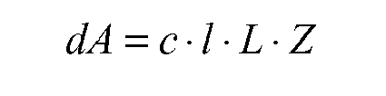
wherein dA is the respective relative movement-dependent wear part, c is an adjustment factor which is independent of the process variables |P|, l is the length of the respective rolling stock segment (16), L is the length of the sliding zone (13) and Z is a further influencing variable which is dependent on the process variables |P|. - Determination method according to claim 2, characterised in that
the further influencing variable |Z| depends on the pressure distribution in the rolling gap. - Determination method according to claim 3, characterised in that- the pressure distribution in the rolling gap is determined upon initial acceptance of the process variables |P| with the aid of the process variables |P| in conjunction with the rolling stand variables |W2| and the rolling stock variables |W1|,- the determined pressure distribution is stored,- with a subsequent acceptance of the process variables |P|, a check is carried out with the aid of the process variables |P| to determine whether the process variables |P| have changed, and- as a function of whether or not the process variables |P| have changed, the pressure distribution in the rolling gap is determined with the aid of the new process variables |P| in conjunction with the rolling stand variables |W2| and the rolling stock variables |W1| or the stored pressure distribution in the rolling gap is used.
- Determination method according to claim 2, 3 or 4, characterised in that
the further influencing variable |Z| depends on the surface hardness of the roller (3). - Determination method according to claim 5, characterised in that
an upper temperature is determined in real-time with the aid of the process variables |P| in conjunction with the roller stand variables |W2| and the rolling stock variables |W1|, to which upper temperature the surface of the roller (3) is heated during contact with the rolling stock (2) and that the surface hardness of the roller (3) is determined as a function of the determined upper temperature. - Determination method according to one of the above claims, characterised in that
a rolling gap lubrication is taken into consideration when determining the sliding zone (13). - Determination method according to one of the above claims, characterised in that
the determined wear |d| is used for the first rolling stand (1) within the scope of determining control variables |S| and/or for determining a roller replacement time. - Determination method according to one of claims 1 to 8, characterised in that- the process variables |P| include a rolling force |FW| occurring when rolling the rolling stock (2),- the rolling force |FW| is detected,- an expected rolling force |FW'| is determined using a flow curve of the rolling stock (2),- the respective relative movement-dependent wear part |dA| is determined as a direct or indirect function of the flow curve, and- the flow curve is traced as a function of the detected rolling force |FW| and the expected rolling force |FW'|.
- Determination method according to one of claims 1 to 8, characterised in that- the process variables P include a rolling force |FW| occurring when rolling the rolling stock (2) and a lead |v| occurring when rolling the rolling stock (2),- the rolling force |FW| and the lead |v| are detected,- an expected rolling force |FW'| and an expected lead |v'| are determined using a flow curve of the rolling stock (2) and a friction coefficient of the rolling stock (2) relative to the roller (3),- the respective relative movement-dependent wear part |dA| is determined as a direct or indirect function of the flow curve and the friction coefficient and- the flow curve and the friction curve are traced as a function of the detected rolling force |FW|, the expected rolling force |FW'|, the detected lead |v| and the expected lead |v'|.
- Determination method according to claim 10, characterised in that
with respect to a roller (3) of a second rolling stand (1), a determination method similar to claim 9 is embodied and a friction coefficient of the rolling stock (3) which is used within the scope of determining the wear |d| of the roller (3) of the second rolling stand (1) is determined relative to the roller (3) of the second rolling stand (1) with the aid of the friction coefficient traced for the first rolling stand (1). - Determination method according to claim 11, characterised in that
the rolling stock (2) initially passes through the second rolling stand (1) and then the first rolling stand (1). - Determination method according to claim 12, characterised in that
the second rolling stand (1) is a cogging stand of a cogging train and the first rolling stand (1) is a finishing stand of a finishing train. - Computer program including machine code (8) which can be processed directly by a computer (5) and the processing of which by means of the computer (5) means that the computer (5) executes a determination method having all steps of a determination method according to one of the above claims.
- Computer,
characterised in that
the computer is embodied such that it executes a determination method having all the steps of a determination method according to one of claims 1 to 13. - Rolling mill including at least one rolling stand (1) for rolling rolling stock (2),
characterised in that
the rolling mill is equipped with a computer (5) according to claim 15.
Priority Applications (3)
| Application Number | Priority Date | Filing Date | Title |
|---|---|---|---|
| PL11175028T PL2548665T3 (en) | 2011-07-22 | 2011-07-22 | Method for determining the wear on a roller dependent on relative movement |
| EP11175028.7A EP2548665B1 (en) | 2011-07-22 | 2011-07-22 | Method for determining the wear on a roller dependent on relative movement |
| CN201210257089.0A CN102886385B (en) | 2011-07-22 | 2012-07-23 | Method for determining relative movement-related degree of wear for roller |
Applications Claiming Priority (1)
| Application Number | Priority Date | Filing Date | Title |
|---|---|---|---|
| EP11175028.7A EP2548665B1 (en) | 2011-07-22 | 2011-07-22 | Method for determining the wear on a roller dependent on relative movement |
Publications (2)
| Publication Number | Publication Date |
|---|---|
| EP2548665A1 EP2548665A1 (en) | 2013-01-23 |
| EP2548665B1 true EP2548665B1 (en) | 2014-02-12 |
Family
ID=44999659
Family Applications (1)
| Application Number | Title | Priority Date | Filing Date |
|---|---|---|---|
| EP11175028.7A Active EP2548665B1 (en) | 2011-07-22 | 2011-07-22 | Method for determining the wear on a roller dependent on relative movement |
Country Status (3)
| Country | Link |
|---|---|
| EP (1) | EP2548665B1 (en) |
| CN (1) | CN102886385B (en) |
| PL (1) | PL2548665T3 (en) |
Cited By (2)
| Publication number | Priority date | Publication date | Assignee | Title |
|---|---|---|---|---|
| EP3685930A1 (en) | 2019-01-28 | 2020-07-29 | Primetals Technologies Germany GmbH | Local varying of the roll gap in the area of the edges of a rolled strip |
| WO2020156787A1 (en) | 2019-01-28 | 2020-08-06 | Primetals Technologies Germany Gmbh | Changing the effective contour of a running surface of a working roll during the hot rolling of rolling stock in a roll stand to form a rolled strip |
Families Citing this family (9)
| Publication number | Priority date | Publication date | Assignee | Title |
|---|---|---|---|---|
| JP6363388B2 (en) | 2014-05-01 | 2018-07-25 | ロレアル | Mist spray equipment |
| US9475526B2 (en) | 2014-08-23 | 2016-10-25 | Caterpillar Inc. | Track link having a wear sensing device |
| US9868482B2 (en) | 2014-10-29 | 2018-01-16 | Caterpillar Inc. | Track roller assembly with a wear measurement system |
| US9592866B2 (en) | 2014-11-06 | 2017-03-14 | Caterpillar Inc. | Track assembly having a wear monitoring system |
| US9557244B2 (en) | 2014-11-10 | 2017-01-31 | Caterpillar Inc. | Thrust bias detection system |
| US9371630B1 (en) | 2014-12-19 | 2016-06-21 | Caterpillar Inc. | Determination of undercarriage idler and roller wear based on final drive speed |
| CN205659983U (en) | 2016-06-15 | 2016-10-26 | 日照宝华新材料有限公司 | ESP production line is with long kilometer number rolling rollers |
| CN106694572B (en) * | 2017-02-28 | 2018-12-04 | 中冶华天工程技术有限公司 | On-line rolling technique adjustment system and method based on roll wear detection |
| CN114589205B (en) * | 2022-04-08 | 2023-03-28 | 燕山大学 | Method for determining online roll changing time node in strip rolling process |
Family Cites Families (8)
| Publication number | Priority date | Publication date | Assignee | Title |
|---|---|---|---|---|
| SU1329858A1 (en) * | 1986-01-03 | 1987-08-15 | Криворожский Филиал Киевского Института Автоматики Им.Хху Съезда Кпсс | Apparatus for automatic check of wear of hot rolling mill rolls |
| JPH02255207A (en) * | 1989-03-30 | 1990-10-16 | Kawasaki Steel Corp | Method for monitoring surface characteristic of rolling roll in hot finish rolling |
| JPH03138013A (en) * | 1989-10-24 | 1991-06-12 | Kawasaki Steel Corp | Control method for work roll bending in rolling of metal plate |
| JPH0417920A (en) * | 1990-05-11 | 1992-01-22 | Furukawa Electric Co Ltd:The | Method for measuring roll life of rolling mill |
| JP4177898B2 (en) | 1996-10-22 | 2008-11-05 | リーナル・ソリューションズ・インコーポレーテッド | Continuous flow-through peritoneal dialysis (CFPD) with controlled intra-abdominal pressure |
| AT407117B (en) | 1997-09-19 | 2000-12-27 | Immuno Ag | FIBRINE SPONGE |
| JP3548514B2 (en) * | 2000-04-13 | 2004-07-28 | 新日本製鐵株式会社 | Prediction method of work roll wear of rolling mill |
| CN101507978B (en) * | 2009-03-20 | 2012-08-22 | 燕山大学 | Worker roller abrasion forecasting method of cold continuous rolling device based on mechanism and operation condition |
-
2011
- 2011-07-22 PL PL11175028T patent/PL2548665T3/en unknown
- 2011-07-22 EP EP11175028.7A patent/EP2548665B1/en active Active
-
2012
- 2012-07-23 CN CN201210257089.0A patent/CN102886385B/en active Active
Cited By (4)
| Publication number | Priority date | Publication date | Assignee | Title |
|---|---|---|---|---|
| EP3685930A1 (en) | 2019-01-28 | 2020-07-29 | Primetals Technologies Germany GmbH | Local varying of the roll gap in the area of the edges of a rolled strip |
| WO2020156787A1 (en) | 2019-01-28 | 2020-08-06 | Primetals Technologies Germany Gmbh | Changing the effective contour of a running surface of a working roll during the hot rolling of rolling stock in a roll stand to form a rolled strip |
| WO2020156781A1 (en) | 2019-01-28 | 2020-08-06 | Primetals Technologies Germany Gmbh | Local modification of the roller nip in the region of the belt edges of a rolled belt |
| US11413669B2 (en) | 2019-01-28 | 2022-08-16 | Primetals Technologies Germany Gmbh | Locally changing the roll gap in the region of the strip edges of a rolled strip |
Also Published As
| Publication number | Publication date |
|---|---|
| CN102886385A (en) | 2013-01-23 |
| EP2548665A1 (en) | 2013-01-23 |
| PL2548665T3 (en) | 2014-07-31 |
| CN102886385B (en) | 2015-04-08 |
Similar Documents
| Publication | Publication Date | Title |
|---|---|---|
| EP2548665B1 (en) | Method for determining the wear on a roller dependent on relative movement | |
| EP1485216B1 (en) | Computer-aided method for determining desired values for controlling elements of profile and surface evenness | |
| EP2170535B1 (en) | Method for adjusting a state of a rolling stock, particularly a near-net strip | |
| EP2195127B1 (en) | Operating method for introducing a product to be rolled into a roll stand of a roll mill, control device, data carrier, and roll mill for rolling a strip-type product to be rolled | |
| EP3107666B1 (en) | Simple advance control of a wedge position of an advance frame | |
| EP2588257B1 (en) | Operating method for a roller mill for rolling flat rolled goods having roller wear prediction | |
| EP2259882B1 (en) | Operating method for a multi-stand rolling mill train comprising a strip thickness detection means that utilizes the continuity equation | |
| EP2697002B1 (en) | Control method for a mill train | |
| EP2527052A1 (en) | Operating method for a mill train | |
| EP1986795B1 (en) | Method for suppressing the influence of roll eccentricities | |
| DE3422762C2 (en) | ||
| DE10211623A1 (en) | Computer-aided determination process comprises feeding input variables to a material flow model which describes a metal strip before and after the passing through a roll stand | |
| EP3917694B1 (en) | Local varying of the roll gap in the area of the edges of a rolled strip | |
| DE19731980A1 (en) | Method for controlling and presetting a rolling stand or a rolling train for rolling a rolled strip | |
| EP3685930B1 (en) | Local varying of the roll gap in the area of the edges of a rolled strip | |
| DE102009043400A1 (en) | Method for the model-based determination of actuator setpoints for the asymmetric actuators of the rolling mills of a hot strip mill | |
| EP2595768B1 (en) | Method for determining wear on a roll for rolling metal stock | |
| EP4061552B1 (en) | Method, control device and rolling mill for the adjustment of an outlet temperature of a metal strip exiting a rolling train | |
| DE102009043401A1 (en) | Method for the model-based determination of actuator setpoints for the symmetrical and asymmetric actuators of the rolling mills of a hot strip mill | |
| EP3851217A1 (en) | Improved roll model adaptation | |
| DE10206758B4 (en) | Strip edge flatness control | |
| EP1919638A1 (en) | Method for thickness regulation during a hot-rolling process | |
| EP3448592B1 (en) | Method for rolling a product to be rolled | |
| DE102021212881A1 (en) | Device and method for producing a rolled metal strip |
Legal Events
| Date | Code | Title | Description |
|---|---|---|---|
| PUAI | Public reference made under article 153(3) epc to a published international application that has entered the european phase |
Free format text: ORIGINAL CODE: 0009012 |
|
| AK | Designated contracting states |
Kind code of ref document: A1 Designated state(s): AL AT BE BG CH CY CZ DE DK EE ES FI FR GB GR HR HU IE IS IT LI LT LU LV MC MK MT NL NO PL PT RO RS SE SI SK SM TR |
|
| AX | Request for extension of the european patent |
Extension state: BA ME |
|
| RAP1 | Party data changed (applicant data changed or rights of an application transferred) |
Owner name: SIEMENS AKTIENGESELLSCHAFT |
|
| 17P | Request for examination filed |
Effective date: 20130605 |
|
| RBV | Designated contracting states (corrected) |
Designated state(s): AL AT BE BG CH CY CZ DE DK EE ES FI FR GB GR HR HU IE IS IT LI LT LU LV MC MK MT NL NO PL PT RO RS SE SI SK SM TR |
|
| GRAP | Despatch of communication of intention to grant a patent |
Free format text: ORIGINAL CODE: EPIDOSNIGR1 |
|
| INTG | Intention to grant announced |
Effective date: 20130822 |
|
| GRAS | Grant fee paid |
Free format text: ORIGINAL CODE: EPIDOSNIGR3 |
|
| GRAA | (expected) grant |
Free format text: ORIGINAL CODE: 0009210 |
|
| AK | Designated contracting states |
Kind code of ref document: B1 Designated state(s): AL AT BE BG CH CY CZ DE DK EE ES FI FR GB GR HR HU IE IS IT LI LT LU LV MC MK MT NL NO PL PT RO RS SE SI SK SM TR |
|
| REG | Reference to a national code |
Ref country code: GB Ref legal event code: FG4D Free format text: NOT ENGLISH |
|
| REG | Reference to a national code |
Ref country code: CH Ref legal event code: EP |
|
| REG | Reference to a national code |
Ref country code: AT Ref legal event code: REF Ref document number: 651894 Country of ref document: AT Kind code of ref document: T Effective date: 20140215 |
|
| REG | Reference to a national code |
Ref country code: IE Ref legal event code: FG4D Free format text: LANGUAGE OF EP DOCUMENT: GERMAN |
|
| REG | Reference to a national code |
Ref country code: DE Ref legal event code: R096 Ref document number: 502011002141 Country of ref document: DE Effective date: 20140327 |
|
| REG | Reference to a national code |
Ref country code: SE Ref legal event code: TRGR |
|
| REG | Reference to a national code |
Ref country code: NL Ref legal event code: VDEP Effective date: 20140212 |
|
| REG | Reference to a national code |
Ref country code: LT Ref legal event code: MG4D |
|
| PG25 | Lapsed in a contracting state [announced via postgrant information from national office to epo] |
Ref country code: IS Free format text: LAPSE BECAUSE OF FAILURE TO SUBMIT A TRANSLATION OF THE DESCRIPTION OR TO PAY THE FEE WITHIN THE PRESCRIBED TIME-LIMIT Effective date: 20140612 Ref country code: LT Free format text: LAPSE BECAUSE OF FAILURE TO SUBMIT A TRANSLATION OF THE DESCRIPTION OR TO PAY THE FEE WITHIN THE PRESCRIBED TIME-LIMIT Effective date: 20140212 Ref country code: NO Free format text: LAPSE BECAUSE OF FAILURE TO SUBMIT A TRANSLATION OF THE DESCRIPTION OR TO PAY THE FEE WITHIN THE PRESCRIBED TIME-LIMIT Effective date: 20140512 |
|
| REG | Reference to a national code |
Ref country code: PL Ref legal event code: T3 |
|
| PG25 | Lapsed in a contracting state [announced via postgrant information from national office to epo] |
Ref country code: NL Free format text: LAPSE BECAUSE OF FAILURE TO SUBMIT A TRANSLATION OF THE DESCRIPTION OR TO PAY THE FEE WITHIN THE PRESCRIBED TIME-LIMIT Effective date: 20140212 Ref country code: CY Free format text: LAPSE BECAUSE OF FAILURE TO SUBMIT A TRANSLATION OF THE DESCRIPTION OR TO PAY THE FEE WITHIN THE PRESCRIBED TIME-LIMIT Effective date: 20140212 Ref country code: ES Free format text: LAPSE BECAUSE OF FAILURE TO SUBMIT A TRANSLATION OF THE DESCRIPTION OR TO PAY THE FEE WITHIN THE PRESCRIBED TIME-LIMIT Effective date: 20140212 Ref country code: FI Free format text: LAPSE BECAUSE OF FAILURE TO SUBMIT A TRANSLATION OF THE DESCRIPTION OR TO PAY THE FEE WITHIN THE PRESCRIBED TIME-LIMIT Effective date: 20140212 Ref country code: PT Free format text: LAPSE BECAUSE OF FAILURE TO SUBMIT A TRANSLATION OF THE DESCRIPTION OR TO PAY THE FEE WITHIN THE PRESCRIBED TIME-LIMIT Effective date: 20140612 |
|
| PG25 | Lapsed in a contracting state [announced via postgrant information from national office to epo] |
Ref country code: RS Free format text: LAPSE BECAUSE OF FAILURE TO SUBMIT A TRANSLATION OF THE DESCRIPTION OR TO PAY THE FEE WITHIN THE PRESCRIBED TIME-LIMIT Effective date: 20140212 Ref country code: HR Free format text: LAPSE BECAUSE OF FAILURE TO SUBMIT A TRANSLATION OF THE DESCRIPTION OR TO PAY THE FEE WITHIN THE PRESCRIBED TIME-LIMIT Effective date: 20140212 Ref country code: LV Free format text: LAPSE BECAUSE OF FAILURE TO SUBMIT A TRANSLATION OF THE DESCRIPTION OR TO PAY THE FEE WITHIN THE PRESCRIBED TIME-LIMIT Effective date: 20140212 |
|
| PG25 | Lapsed in a contracting state [announced via postgrant information from national office to epo] |
Ref country code: DK Free format text: LAPSE BECAUSE OF FAILURE TO SUBMIT A TRANSLATION OF THE DESCRIPTION OR TO PAY THE FEE WITHIN THE PRESCRIBED TIME-LIMIT Effective date: 20140212 Ref country code: EE Free format text: LAPSE BECAUSE OF FAILURE TO SUBMIT A TRANSLATION OF THE DESCRIPTION OR TO PAY THE FEE WITHIN THE PRESCRIBED TIME-LIMIT Effective date: 20140212 Ref country code: CZ Free format text: LAPSE BECAUSE OF FAILURE TO SUBMIT A TRANSLATION OF THE DESCRIPTION OR TO PAY THE FEE WITHIN THE PRESCRIBED TIME-LIMIT Effective date: 20140212 Ref country code: RO Free format text: LAPSE BECAUSE OF FAILURE TO SUBMIT A TRANSLATION OF THE DESCRIPTION OR TO PAY THE FEE WITHIN THE PRESCRIBED TIME-LIMIT Effective date: 20140212 |
|
| REG | Reference to a national code |
Ref country code: DE Ref legal event code: R097 Ref document number: 502011002141 Country of ref document: DE |
|
| PG25 | Lapsed in a contracting state [announced via postgrant information from national office to epo] |
Ref country code: SK Free format text: LAPSE BECAUSE OF FAILURE TO SUBMIT A TRANSLATION OF THE DESCRIPTION OR TO PAY THE FEE WITHIN THE PRESCRIBED TIME-LIMIT Effective date: 20140212 |
|
| PLBE | No opposition filed within time limit |
Free format text: ORIGINAL CODE: 0009261 |
|
| STAA | Information on the status of an ep patent application or granted ep patent |
Free format text: STATUS: NO OPPOSITION FILED WITHIN TIME LIMIT |
|
| 26N | No opposition filed |
Effective date: 20141113 |
|
| REG | Reference to a national code |
Ref country code: DE Ref legal event code: R097 Ref document number: 502011002141 Country of ref document: DE Effective date: 20141113 |
|
| PG25 | Lapsed in a contracting state [announced via postgrant information from national office to epo] |
Ref country code: LU Free format text: LAPSE BECAUSE OF FAILURE TO SUBMIT A TRANSLATION OF THE DESCRIPTION OR TO PAY THE FEE WITHIN THE PRESCRIBED TIME-LIMIT Effective date: 20140722 |
|
| REG | Reference to a national code |
Ref country code: CH Ref legal event code: PL |
|
| PG25 | Lapsed in a contracting state [announced via postgrant information from national office to epo] |
Ref country code: IT Free format text: LAPSE BECAUSE OF FAILURE TO SUBMIT A TRANSLATION OF THE DESCRIPTION OR TO PAY THE FEE WITHIN THE PRESCRIBED TIME-LIMIT Effective date: 20140212 |
|
| REG | Reference to a national code |
Ref country code: IE Ref legal event code: MM4A |
|
| PG25 | Lapsed in a contracting state [announced via postgrant information from national office to epo] |
Ref country code: CH Free format text: LAPSE BECAUSE OF NON-PAYMENT OF DUE FEES Effective date: 20140731 Ref country code: LI Free format text: LAPSE BECAUSE OF NON-PAYMENT OF DUE FEES Effective date: 20140731 |
|
| PG25 | Lapsed in a contracting state [announced via postgrant information from national office to epo] |
Ref country code: SI Free format text: LAPSE BECAUSE OF FAILURE TO SUBMIT A TRANSLATION OF THE DESCRIPTION OR TO PAY THE FEE WITHIN THE PRESCRIBED TIME-LIMIT Effective date: 20140212 |
|
| REG | Reference to a national code |
Ref country code: FR Ref legal event code: PLFP Year of fee payment: 5 |
|
| REG | Reference to a national code |
Ref country code: DE Ref legal event code: R081 Ref document number: 502011002141 Country of ref document: DE Owner name: PRIMETALS TECHNOLOGIES GERMANY GMBH, DE Free format text: FORMER OWNER: SIEMENS AKTIENGESELLSCHAFT, 80333 MUENCHEN, DE |
|
| PG25 | Lapsed in a contracting state [announced via postgrant information from national office to epo] |
Ref country code: IE Free format text: LAPSE BECAUSE OF NON-PAYMENT OF DUE FEES Effective date: 20140722 |
|
| REG | Reference to a national code |
Ref country code: FR Ref legal event code: TP Owner name: PRIMETALS TECHNOLOGIES GERMANY GMBH, DE Effective date: 20151105 |
|
| GBPC | Gb: european patent ceased through non-payment of renewal fee |
Effective date: 20150722 |
|
| PG25 | Lapsed in a contracting state [announced via postgrant information from national office to epo] |
Ref country code: MC Free format text: LAPSE BECAUSE OF FAILURE TO SUBMIT A TRANSLATION OF THE DESCRIPTION OR TO PAY THE FEE WITHIN THE PRESCRIBED TIME-LIMIT Effective date: 20140212 Ref country code: GB Free format text: LAPSE BECAUSE OF NON-PAYMENT OF DUE FEES Effective date: 20150722 Ref country code: SM Free format text: LAPSE BECAUSE OF FAILURE TO SUBMIT A TRANSLATION OF THE DESCRIPTION OR TO PAY THE FEE WITHIN THE PRESCRIBED TIME-LIMIT Effective date: 20140212 |
|
| PG25 | Lapsed in a contracting state [announced via postgrant information from national office to epo] |
Ref country code: GR Free format text: LAPSE BECAUSE OF FAILURE TO SUBMIT A TRANSLATION OF THE DESCRIPTION OR TO PAY THE FEE WITHIN THE PRESCRIBED TIME-LIMIT Effective date: 20140513 Ref country code: MT Free format text: LAPSE BECAUSE OF FAILURE TO SUBMIT A TRANSLATION OF THE DESCRIPTION OR TO PAY THE FEE WITHIN THE PRESCRIBED TIME-LIMIT Effective date: 20140212 Ref country code: BG Free format text: LAPSE BECAUSE OF FAILURE TO SUBMIT A TRANSLATION OF THE DESCRIPTION OR TO PAY THE FEE WITHIN THE PRESCRIBED TIME-LIMIT Effective date: 20140212 |
|
| REG | Reference to a national code |
Ref country code: FR Ref legal event code: PLFP Year of fee payment: 6 |
|
| PG25 | Lapsed in a contracting state [announced via postgrant information from national office to epo] |
Ref country code: HU Free format text: LAPSE BECAUSE OF FAILURE TO SUBMIT A TRANSLATION OF THE DESCRIPTION OR TO PAY THE FEE WITHIN THE PRESCRIBED TIME-LIMIT; INVALID AB INITIO Effective date: 20110722 Ref country code: BE Free format text: LAPSE BECAUSE OF FAILURE TO SUBMIT A TRANSLATION OF THE DESCRIPTION OR TO PAY THE FEE WITHIN THE PRESCRIBED TIME-LIMIT Effective date: 20140731 |
|
| PGFP | Annual fee paid to national office [announced via postgrant information from national office to epo] |
Ref country code: PL Payment date: 20160624 Year of fee payment: 6 Ref country code: TR Payment date: 20160624 Year of fee payment: 6 |
|
| PGFP | Annual fee paid to national office [announced via postgrant information from national office to epo] |
Ref country code: FR Payment date: 20160721 Year of fee payment: 6 |
|
| REG | Reference to a national code |
Ref country code: AT Ref legal event code: MM01 Ref document number: 651894 Country of ref document: AT Kind code of ref document: T Effective date: 20160722 |
|
| PG25 | Lapsed in a contracting state [announced via postgrant information from national office to epo] |
Ref country code: AT Free format text: LAPSE BECAUSE OF NON-PAYMENT OF DUE FEES Effective date: 20160722 |
|
| REG | Reference to a national code |
Ref country code: FR Ref legal event code: ST Effective date: 20180330 |
|
| PG25 | Lapsed in a contracting state [announced via postgrant information from national office to epo] |
Ref country code: FR Free format text: LAPSE BECAUSE OF NON-PAYMENT OF DUE FEES Effective date: 20170731 |
|
| PG25 | Lapsed in a contracting state [announced via postgrant information from national office to epo] |
Ref country code: MK Free format text: LAPSE BECAUSE OF FAILURE TO SUBMIT A TRANSLATION OF THE DESCRIPTION OR TO PAY THE FEE WITHIN THE PRESCRIBED TIME-LIMIT Effective date: 20140212 |
|
| PG25 | Lapsed in a contracting state [announced via postgrant information from national office to epo] |
Ref country code: AL Free format text: LAPSE BECAUSE OF FAILURE TO SUBMIT A TRANSLATION OF THE DESCRIPTION OR TO PAY THE FEE WITHIN THE PRESCRIBED TIME-LIMIT Effective date: 20140212 |
|
| PG25 | Lapsed in a contracting state [announced via postgrant information from national office to epo] |
Ref country code: PL Free format text: LAPSE BECAUSE OF NON-PAYMENT OF DUE FEES Effective date: 20170722 |
|
| REG | Reference to a national code |
Ref country code: DE Ref legal event code: R081 Ref document number: 502011002141 Country of ref document: DE Owner name: PRIMETALS TECHNOLOGIES GERMANY GMBH, DE Free format text: FORMER OWNER: PRIMETALS TECHNOLOGIES GERMANY GMBH, 91052 ERLANGEN, DE |
|
| PG25 | Lapsed in a contracting state [announced via postgrant information from national office to epo] |
Ref country code: TR Free format text: LAPSE BECAUSE OF NON-PAYMENT OF DUE FEES Effective date: 20170722 |
|
| PGFP | Annual fee paid to national office [announced via postgrant information from national office to epo] |
Ref country code: SE Payment date: 20230719 Year of fee payment: 13 Ref country code: DE Payment date: 20230719 Year of fee payment: 13 |