EP2547153A2 - Method for establishing a wireless link for a computer - Google Patents
Method for establishing a wireless link for a computer Download PDFInfo
- Publication number
- EP2547153A2 EP2547153A2 EP12166332A EP12166332A EP2547153A2 EP 2547153 A2 EP2547153 A2 EP 2547153A2 EP 12166332 A EP12166332 A EP 12166332A EP 12166332 A EP12166332 A EP 12166332A EP 2547153 A2 EP2547153 A2 EP 2547153A2
- Authority
- EP
- European Patent Office
- Prior art keywords
- access point
- wireless module
- internet
- executing
- computer
- Prior art date
- Legal status (The legal status is an assumption and is not a legal conclusion. Google has not performed a legal analysis and makes no representation as to the accuracy of the status listed.)
- Withdrawn
Links
Images



Classifications
-
- H—ELECTRICITY
- H04—ELECTRIC COMMUNICATION TECHNIQUE
- H04W—WIRELESS COMMUNICATION NETWORKS
- H04W48/00—Access restriction; Network selection; Access point selection
- H04W48/16—Discovering, processing access restriction or access information
-
- G—PHYSICS
- G06—COMPUTING OR CALCULATING; COUNTING
- G06F—ELECTRIC DIGITAL DATA PROCESSING
- G06F1/00—Details not covered by groups G06F3/00 - G06F13/00 and G06F21/00
- G06F1/16—Constructional details or arrangements
- G06F1/1613—Constructional details or arrangements for portable computers
- G06F1/1633—Constructional details or arrangements of portable computers not specific to the type of enclosures covered by groups G06F1/1615 - G06F1/1626
- G06F1/1684—Constructional details or arrangements related to integrated I/O peripherals not covered by groups G06F1/1635 - G06F1/1675
- G06F1/1698—Constructional details or arrangements related to integrated I/O peripherals not covered by groups G06F1/1635 - G06F1/1675 the I/O peripheral being a sending/receiving arrangement to establish a cordless communication link, e.g. radio or infrared link, integrated cellular phone
-
- H—ELECTRICITY
- H04—ELECTRIC COMMUNICATION TECHNIQUE
- H04W—WIRELESS COMMUNICATION NETWORKS
- H04W88/00—Devices specially adapted for wireless communication networks, e.g. terminals, base stations or access point devices
- H04W88/02—Terminal devices
Definitions
- the present invention is related to a method for establishing a wireless link for a computer, and more particularly, to a method for efficiently establishing a wireless link for a computer according to the pre-characterizing clause of claim 1.
- Wireless communication technologies such as Wifi (Wireless Fidelity), 3G (third-generation) and bluetooth, are widely used in mobile devices, such as smart phones, personal computers (PCs), tablet PCs and notebook PCs, for allowing users to surf the Internet.
- mobile devices such as smart phones, personal computers (PCs), tablet PCs and notebook PCs
- AP access points
- BIOS basic input output system
- OS operation system
- the computer can finally be linked to the Internet wirelessly according to inputted instructions, or via an installed software program automatically.
- linking the computer to the Internet wirelessly can only be implemented after executing the BIOS and initializing the OS. Therefore, the user has to wait for a long time before the computer can be linked to the Internet wirelessly.
- the present invention aims at providing a method of performing a recovery operation which prevents a functional storage device from being dropped when the failure of the recovery operation is caused by a temporary device error.
- the claimed method for establishing a wireless link for a computer includes executing a basic input output system (BIOS), using a wireless module built in the computer to scan at least one nearby access point when executing the BIOS, and linking the wireless module to an access point of the at least one access point.
- BIOS basic input output system
- FIG. 1 is a diagram showing a computer 30 linked to an Internet 70 in a wireless communication environment 100 according to the present invention.
- a wireless module 32 built in the computer 30 is used to scan at least one nearby access point. After an access point 20 is found via scanning, the computer 30 is linked to the Internet 70 through the access point 20.
- the wireless module 32 can be a Wifi, 3G or bluetooth wireless module. Please notice that each of the access points described above and below may be a wireless module of an electronic device.
- FIG. 2 is a flowchart showing the computer 30 linked to the Internet 70 through the access point 20 according to a first embodiment of the present invention. The flowchart is described as follows:
- the computer 30 may scan nearby access points with the built-in wireless module 32, or the wireless module 32 may scan nearby access points automatically when the computer 30 executes the BIOS.
- the wireless module 32 will compare each access point with the access point preference list of the wireless module 32 so as to link to a preferred access point 20 wirelessly.
- the access point preference list is updated according to priority and/or frequency of using the access point 20.
- the wireless module 32 tends to select a more frequently linked access point to establish a wireless link according to the access point preference list.
- the wireless module 32 can be allocated a static IP or a floating IP allocated through the dynamic host configuration protocol (DHCP).
- DHCP dynamic host configuration protocol
- the wireless module 32 can be linked to the Internet 70 via the access point 20 with the allocated static IP or floating IP.
- the computer 30 updates data through the Internet 70. Since the computer 30 has updated data before the desktop image is displayed in Step 220, the user can access the Internet 70 immediately after the desktop image is displayed. That is, the user does not have to spend additional time waiting for the wireless module 32 to search for an access point and link to the Internet 70 after the desktop image is displayed.
- FIG. 3 is a flowchart showing the computer 30 linked to the Internet 70 through the access point 20 according to a second embodiment of the present invention. The flowchart is described as follows:
- the difference between the second embodiment and the first embodiment is that in the second embodiment, the wireless module 32 has been linked to the access point 20 in Step 308 when executing the BIOS. In Step 314 or 316, the computer 30 has linked to the Internet 70 via the access point 20. Similarly, through utilizing the method and device provided in the second embodiment, the user can access the Internet 70 immediately after the desktop image is displayed. That is, the user does not have to spend additional time waiting for the wireless module 32 to search for an access point and link to the Internet 70 after the desktop image is displayed.
- FIG. 4 is a flowchart showing the computer 30 linked to the Internet 70 through the access point 20 according to a third embodiment of the present invention. The flowchart is described as follows:
- the access point 20 to be linked to the wireless module 32 is selected after the operating system is initialized.
- the user can access the Internet 70 immediately after the desktop image is displayed. That is, the user does not have to spend additional time waiting for the wireless module 32 to search for an access point and link to the Internet 70 after the desktop image is displayed.
- FIG. 5 is a flowchart showing the computer 30 linked to the Internet 70 through the access point 20 according to a fourth embodiment of the present invention. The flowchart is described as follows:
- the computer 30 has linked the wireless module 32 to the access point 20 in Step 508 and has linked the wireless module 32 to the Internet 70 in Step 510 or Step 512 when executing the BIOS and before executing the system driving program in order to update data of the computer 30 through the Internet 70.
- the user can access the Internet 70 immediately after the desktop image is displayed. That is, the user does not have to spend additional time waiting for the wireless module 32 to search for an access point and link to the Internet 70 after the desktop image is displayed.
- the computer 30 can be linked to the Internet 70 via the access point 20 before the OS is initialized. Therefore, after the OS is initialized, the user can access the Internet 70 immediately without spending additional time waiting for the wireless module 32 to search for an access point.
Landscapes
- Engineering & Computer Science (AREA)
- Computer Hardware Design (AREA)
- General Engineering & Computer Science (AREA)
- Theoretical Computer Science (AREA)
- Human Computer Interaction (AREA)
- Physics & Mathematics (AREA)
- General Physics & Mathematics (AREA)
- Computer Security & Cryptography (AREA)
- Computer Networks & Wireless Communication (AREA)
- Signal Processing (AREA)
- Mobile Radio Communication Systems (AREA)
- Small-Scale Networks (AREA)
Abstract
Description
- The present invention is related to a method for establishing a wireless link for a computer, and more particularly, to a method for efficiently establishing a wireless link for a computer according to the pre-characterizing clause of claim 1.
- Wireless communication technologies, such as Wifi (Wireless Fidelity), 3G (third-generation) and bluetooth, are widely used in mobile devices, such as smart phones, personal computers (PCs), tablet PCs and notebook PCs, for allowing users to surf the Internet. Besides, more and more access points (AP) for wirelessly linking to the Internet are being setup throughout cities. Thus, establishing a wireless link between a mobile device and an Internet efficiently has become an important issue.
- Before establishing a wireless link between a computer and the Internet, a user must turn on the computer first to execute a basic input output system (BIOS). After executing the BIOS, an operation system (OS) is initialized. After the OS is initialized, the computer can finally be linked to the Internet wirelessly according to inputted instructions, or via an installed software program automatically.
- In the aforementioned procedures, linking the computer to the Internet wirelessly can only be implemented after executing the BIOS and initializing the OS. Therefore, the user has to wait for a long time before the computer can be linked to the Internet wirelessly.
- This in mind, the present invention aims at providing a method of performing a recovery operation which prevents a functional storage device from being dropped when the failure of the recovery operation is caused by a temporary device error.
- This is achieved by a method for establishing a wireless link for a computer according to claim 1. The dependent claims pertain to corresponding further developments and improvements.
- As will be seen more clearly from the detailed description following below, the claimed method for establishing a wireless link for a computer includes executing a basic input output system (BIOS), using a wireless module built in the computer to scan at least one nearby access point when executing the BIOS, and linking the wireless module to an access point of the at least one access point.
- In the following, the invention is further illustrated by way of example, taking reference to the accompanying drawings thereof:
-
FIG. 1 is a diagram of a computer linked to an Internet in a wireless communication environment according to the present invention; -
FIG. 2 is a flowchart showing the computer linked to the Internet through an access point according to a first embodiment of the present invention; -
FIG. 3 is a flowchart showing the computer linked to the Internet through an access point according to a second embodiment of the present invention; -
FIG. 4 is a flowchart showing the computer linked to the Internet through an access point according to a third embodiment of the present invention; and -
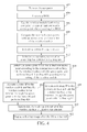
FIG. 5 is a flowchart showing the computer linked to the Internet through an access point in according to a fourth embodiment of the present invention. - Please refer to
FIG. 1. FIG. 1 is a diagram showing acomputer 30 linked to an Internet 70 in awireless communication environment 100 according to the present invention. As depicted inFIG. 1 , awireless module 32 built in thecomputer 30 is used to scan at least one nearby access point. After anaccess point 20 is found via scanning, thecomputer 30 is linked to the Internet 70 through theaccess point 20. Thewireless module 32 can be a Wifi, 3G or bluetooth wireless module. Please notice that each of the access points described above and below may be a wireless module of an electronic device. - Please refer to
FIG. 2. FIG. 2 is a flowchart showing thecomputer 30 linked to the Internet 70 through theaccess point 20 according to a first embodiment of the present invention. The flowchart is described as follows: - Step 202:
- turn on the
computer 30; - Step 204:
- execute a BIOS;
- Step 206:
- use the
wireless module 32 built in thecomputer 30 to scan at least one nearby access point when executing the BIOS; - Step 208:
- execute a system driving program;
- Step 210:
- initialize an operating system after executing the system driving program;
- Step 212:
- select an
access point 20 from the at least one access point according to an access point preference list of thewireless module 32, link thewireless module 32 with theaccess point 20, and performStep 214 orStep 216 according to the setting of thewireless module 32; - Step 214:
- allocate a static IP (Internet protocol) to the
wireless module 32 and link thewireless module 32 to the Internet 70 through theaccess point 20 with the static IP, and performStep 218; - Step 216:
- allocate a floating IP to the
wireless module 32 and link thewireless module 32 to the Internet 70 through theaccess point 20 with the floating IP, and performStep 218; - Step 218:
- update data through the Internet 70 after the
wireless module 32 is linked to the Internet 70; - Step 220:
- display a desktop image after the OS is initialized.
- In
Steps 202 to 220, thecomputer 30 may scan nearby access points with the built-inwireless module 32, or thewireless module 32 may scan nearby access points automatically when thecomputer 30 executes the BIOS. When multiple access points are found, thewireless module 32 will compare each access point with the access point preference list of thewireless module 32 so as to link to apreferred access point 20 wirelessly. The access point preference list is updated according to priority and/or frequency of using theaccess point 20. Thus thewireless module 32 tends to select a more frequently linked access point to establish a wireless link according to the access point preference list. Thewireless module 32 can be allocated a static IP or a floating IP allocated through the dynamic host configuration protocol (DHCP). Thus, inStep 214 orStep 216, thewireless module 32 can be linked to the Internet 70 via theaccess point 20 with the allocated static IP or floating IP. InStep 218, thecomputer 30 updates data through the Internet 70. Since thecomputer 30 has updated data before the desktop image is displayed inStep 220, the user can access the Internet 70 immediately after the desktop image is displayed. That is, the user does not have to spend additional time waiting for thewireless module 32 to search for an access point and link to the Internet 70 after the desktop image is displayed. - Please refer to
FIG. 3. FIG. 3 is a flowchart showing thecomputer 30 linked to the Internet 70 through theaccess point 20 according to a second embodiment of the present invention. The flowchart is described as follows: - Step 302:
- turn on the
computer 30; - Step 304:
- execute a BIOS;
- Step 306:
- use the
wireless module 32 built in thecomputer 30 to scan at least one nearby access point when executing the BIOS; - Step 308:
- select an
access point 20 from the at least one access point according to an access point preference list of thewireless module 32, and link thewireless module 32 with theaccess point 20 when executing the BIOS; - Step 310:
- execute a system driving program;
- Step 312:
- initialize an operating system after executing the system driving program, and perform
Step 314 orStep 316 according to the setting of thewireless module 32; - Step 314:
- allocate a static (Internet protocol) IP to the
wireless module 32 and link thewireless module 32 to theInternet 70 through theaccess point 20 with the static IP, and performStep 318; - Step 316:
- allocate a floating IP to the
wireless module 32 and link thewireless module 32 to theInternet 70 through theaccess point 20 with the floating IP, and performStep 318; - Step 318:
- update data through the
Internet 70 after thewireless module 32 is linked to theInternet 70; - Step 320:
- display a desktop image after the OS is initialized.
- The difference between the second embodiment and the first embodiment is that in the second embodiment, the
wireless module 32 has been linked to theaccess point 20 inStep 308 when executing the BIOS. InStep computer 30 has linked to theInternet 70 via theaccess point 20. Similarly, through utilizing the method and device provided in the second embodiment, the user can access theInternet 70 immediately after the desktop image is displayed. That is, the user does not have to spend additional time waiting for thewireless module 32 to search for an access point and link to theInternet 70 after the desktop image is displayed. - Please refer to
FIG. 4. FIG. 4 is a flowchart showing thecomputer 30 linked to theInternet 70 through theaccess point 20 according to a third embodiment of the present invention. The flowchart is described as follows: - Step 402:
- turn on the
computer 30; - Step 404:
- execute a BIOS;
- Step 406:
- use the
wireless module 32 built in thecomputer 30 to scan at least one nearby access point when executing the BIOS; - Step 408:
- compare the searched access points with an access point preference list of the
wireless module 32; - Step 410:
- execute a system driving program;
- Step 412:
- initialize an operating system after executing the system driving program;
- Step 414:
- select an
access point 20 from the at least one access point according to the comparison result inStep 408, link thewireless module 32 with theaccess point 20, and performStep 416 orStep 418 according to the setting of thewireless module 32; - Step 416:
- allocate a static IP to the
wireless module 32 and link thewireless module 32 to theInternet 70 through theaccess point 20 with the static IP, and performStep 420; - Step 418:
- allocate a floating IP to the
wireless module 32 and link thewireless module 32 to theInternet 70 through theaccess point 20 with the floating IP, and performStep 420; - Step 420:
- update data through the
Internet 70 after thewireless module 32 is linked to theInternet 70; - Step 422:
- display a desktop image after the OS is initialized.
- The difference between the third embodiment and the first embodiment is that in the third embodiment, the
access point 20 to be linked to thewireless module 32 is selected after the operating system is initialized. Similarly, through utilizing the method and device provided in the third embodiment, the user can access theInternet 70 immediately after the desktop image is displayed. That is, the user does not have to spend additional time waiting for thewireless module 32 to search for an access point and link to theInternet 70 after the desktop image is displayed. - Please refer to
FIG. 5. FIG. 5 is a flowchart showing thecomputer 30 linked to theInternet 70 through theaccess point 20 according to a fourth embodiment of the present invention. The flowchart is described as follows: - Step 502:
- turn on the
computer 30; - Step 504:
- execute a BIOS;
- Step 506:
- use the
wireless module 32 built in thecomputer 30 to scan at least one nearby access point when executing the BIOS; - Step 508:
- select an
access point 20 from the at least one access point according to an access point preference list of thewireless module 32, and link thewireless module 32 with theaccess point 20 when executing the BIOS, and performStep 510 orStep 512 according to the setting of thewireless module 32; - Step 510:
- allocate a static IP to the
wireless module 32 and link thewireless module 32 to theInternet 70 through theaccess point 20 with the static IP when executing the BIOS, and performStep 514; - Step 512:
- allocate a floating IP to the
wireless module 32 and link thewireless module 32 to theInternet 70 through theaccess point 20 with the floating IP when executing the BIOS, and performStep 514; - Step 514:
- update data through the
Internet 70 after thewireless module 32 is linked to theInternet 70; - Step 516:
- execute a system driving program;
- Step 518:
- initialize an operating system after executing the system driving program;
- Step 520:
- display a desktop image after the OS is initialized.
- The difference between the fourth embodiment and the second embodiment is that in the fourth embodiment, the
computer 30 has linked thewireless module 32 to theaccess point 20 inStep 508 and has linked thewireless module 32 to theInternet 70 inStep 510 orStep 512 when executing the BIOS and before executing the system driving program in order to update data of thecomputer 30 through theInternet 70. Similarly, through utilizing the method and device provided in the fourth embodiment, the user can access theInternet 70 immediately after the desktop image is displayed. That is, the user does not have to spend additional time waiting for thewireless module 32 to search for an access point and link to theInternet 70 after the desktop image is displayed. - In view of above, through utilizing the method and device provided in the present invention, the
computer 30 can be linked to theInternet 70 via theaccess point 20 before the OS is initialized. Therefore, after the OS is initialized, the user can access theInternet 70 immediately without spending additional time waiting for thewireless module 32 to search for an access point.
Claims (20)
- A method for establishing a wireless link for a computer comprising:executing a basic input output system; characterized by:using a wireless module built in the computer to scan at least one nearby access point when executing the basic input output system; andlinking the wireless module to an access point among the at least one access point.
- The method of claim 1 , characterized in that the access point is a wireless module of an electronic device.
- The method of claim 1 , further characterized by:selecting the access point among the at least one access point according to an access point preference list.
- The method of claim 3, further characterized by:updating the access point preference list according to a priority and/or a frequency of using the at least one access point.
- The method of claim 3, characterized in that selecting the access point is performed when executing the basic input output system.
- The method of claim 1, characterized in that linking the wireless module to the access point is performed when executing the basic input output system.
- The method of claim 1 , further characterized by:executing a system driving program.
- The method of claim 7, further characterized by:initializing an operating system after executing the system driving program.
- The method of claim 8, further characterized by:selecting the access point among the at least one access point according to an access point preference list when initializing the operating system.
- The method of claim 9, further characterized by:updating the access point preference list according to a priority and/or a frequency of using the at least one access point.
- The method of claim 8, characterized in that linking the wireless module to the access point is performed when initializing the operating system.
- The method of claim 8, further characterized by:allocating a static Internet protocol to the wireless module when initializing the operating system;linking the wireless module to an Internet through the access point according to the static Internet protocol when initializing the operating system; andthe computer updating data through the Internet when initializing the operating system.
- The method of claim 1 , further characterized by:allocating a static Internet protocol to the wireless module when executing the basic input output system.
- The method of claim 13, further characterized by:linking the wireless module to an Internet through the access point according to the static IP when executing the basic input output system.
- The method of claim 14, further characterized by:the computer updating data through the Internet when executing the basic input output system.
- The method of claim 8, further characterized by:allocating a floating Internet protocol to the wireless module when initializing the operating system;linking the wireless module to an Internet through the access point according to the floating Internet protocol when initializing the operating system; andthe computer updating data through the Internet when initializing the operating system.
- The method of claim 1 , further characterized by:allocating a floating Internet protocol to the wireless module when executing the basic input output system.
- The method of claim 17, further characterized by:linking the wireless module to an Internet through the access point according to the floating Internet protocol when executing the basic input output system.
- The method of claim 18, further characterized by:the computer updating data through the Internet when executing the basic input output system.
- The method of claim 1 , characterized in that the wireless module is a Wireless Fidelity, a third-generation or a bluetooth wireless module.
Applications Claiming Priority (3)
| Application Number | Priority Date | Filing Date | Title |
|---|---|---|---|
| US201161506647P | 2011-07-12 | 2011-07-12 | |
| US201161506650P | 2011-07-12 | 2011-07-12 | |
| TW100149521A TWI450626B (en) | 2011-07-12 | 2011-12-29 | Method of establishing a wireless link for a computer device |
Publications (2)
| Publication Number | Publication Date |
|---|---|
| EP2547153A2 true EP2547153A2 (en) | 2013-01-16 |
| EP2547153A3 EP2547153A3 (en) | 2015-09-09 |
Family
ID=47484500
Family Applications (1)
| Application Number | Title | Priority Date | Filing Date |
|---|---|---|---|
| EP12166332.2A Withdrawn EP2547153A3 (en) | 2011-07-12 | 2012-05-02 | Method for establishing a wireless link for a computer |
Country Status (4)
| Country | Link |
|---|---|
| US (1) | US20130019088A1 (en) |
| EP (1) | EP2547153A3 (en) |
| CN (1) | CN102883406A (en) |
| TW (1) | TWI450626B (en) |
Family Cites Families (13)
| Publication number | Priority date | Publication date | Assignee | Title |
|---|---|---|---|---|
| JP3799289B2 (en) * | 2002-04-18 | 2006-07-19 | インターナショナル・ビジネス・マシーンズ・コーポレーション | Computer apparatus and wireless system setting method |
| US7203183B2 (en) * | 2002-06-26 | 2007-04-10 | International Business Machines Corporation | Access point initiated forced roaming based upon bandwidth |
| US7652995B2 (en) * | 2003-12-19 | 2010-01-26 | International Business Machines Corporation | Autonomic reassociation of clients in a wireless local area network |
| US7275165B2 (en) * | 2004-03-22 | 2007-09-25 | Dell Products L.P. | Information handling system including wireless scanning feature |
| CN1705290A (en) * | 2004-06-03 | 2005-12-07 | 华为技术有限公司 | Method for accessing WLAN |
| US7480521B2 (en) * | 2005-09-15 | 2009-01-20 | Research In Motion Limited | Methods and apparatus for reducing power consumption during network scanning operations with adverse battery conditions |
| US7793339B2 (en) * | 2005-09-28 | 2010-09-07 | Hewlett-Packard Development Company, L.P. | Devices and methods of using network information in an authorization process |
| CN1988487A (en) * | 2005-12-22 | 2007-06-27 | 佛山市顺德区顺达电脑厂有限公司 | Method for automatic detecting radio network |
| JP4267018B2 (en) * | 2006-10-06 | 2009-05-27 | レノボ・シンガポール・プライベート・リミテッド | Portable computer capable of wireless communication and method of detecting access point |
| US9288751B2 (en) * | 2007-08-29 | 2016-03-15 | Qualcomm Incorporated | Use of position data to select wireless access point |
| TW200925881A (en) * | 2007-12-14 | 2009-06-16 | Inventec Corp | Notebook having a separatable warless communication module |
| CN101801106A (en) * | 2010-01-22 | 2010-08-11 | 深圳市权智掌上电脑有限公司 | WiFi access point connecting system and connecting method |
| US8560822B1 (en) * | 2011-05-26 | 2013-10-15 | Phoenix Technologies Ltd. | Pre-boot operating environment |
-
2011
- 2011-12-29 TW TW100149521A patent/TWI450626B/en active
-
2012
- 2012-01-31 CN CN2012100218981A patent/CN102883406A/en active Pending
- 2012-04-17 US US13/449,306 patent/US20130019088A1/en not_active Abandoned
- 2012-05-02 EP EP12166332.2A patent/EP2547153A3/en not_active Withdrawn
Non-Patent Citations (1)
| Title |
|---|
| None |
Also Published As
| Publication number | Publication date |
|---|---|
| US20130019088A1 (en) | 2013-01-17 |
| CN102883406A (en) | 2013-01-16 |
| TW201304587A (en) | 2013-01-16 |
| EP2547153A3 (en) | 2015-09-09 |
| TWI450626B (en) | 2014-08-21 |
Similar Documents
| Publication | Publication Date | Title |
|---|---|---|
| CN114415787B (en) | Electronic device and method for configuring display of the electronic device | |
| US20130055254A1 (en) | Methods and apparatuses for providing a virtual machine with dynamic assignment of a physical hardware resource | |
| JP6362761B2 (en) | Roaming network access method and apparatus | |
| EP2735133B1 (en) | Method and apparatus for providing data entry content to a remote environment | |
| CN103455348B (en) | Subarea adjustment, device, terminal, server and system | |
| US20140256316A1 (en) | Method and electronic device for network search | |
| CN106372102B (en) | Electronic device and method for managing objects in folders on the electronic device | |
| US10310722B2 (en) | Method and electronic device for controlling scroll speed of content | |
| US20190163293A1 (en) | Cross application digital ink repository | |
| CN105389076A (en) | METHOD OF PROVIDING NOTIFICATION BY ELECTRONIC DEVICE and ELECTRONIC DEVICE | |
| EP2631792A1 (en) | Apparatus and method for verifying operating system of host device in portable terminal | |
| US20150378599A1 (en) | Method and electronic device for displaying virtual keyboard | |
| JP2018535462A (en) | Touch heat map | |
| CN106168901A (en) | Application program font customizing method and control method and related device | |
| US9880799B1 (en) | Extendable display screens of electronic devices | |
| US8799542B2 (en) | System and method for providing remote device driver | |
| EP2869604A1 (en) | Method, apparatus and device for processing a mobile terminal resource | |
| CN110196662A (en) | A kind of method, apparatus, terminal and storage medium showing synchronous regime | |
| US20160080293A1 (en) | Accounts Control | |
| CN104965692B (en) | The method and system of striding course display data in desktop application | |
| US10564803B2 (en) | Selecting application that can handle data content | |
| CN106648607B (en) | Application starting method and device based on icon switching and terminal equipment | |
| CN103927197B (en) | Method and apparatus for executing application in an electronic | |
| KR102884741B1 (en) | Electronic device and Method for controlling the electronic device thereof | |
| US11606457B2 (en) | Technology and method for selectively providing network function to application of device |
Legal Events
| Date | Code | Title | Description |
|---|---|---|---|
| PUAI | Public reference made under article 153(3) epc to a published international application that has entered the european phase |
Free format text: ORIGINAL CODE: 0009012 |
|
| AK | Designated contracting states |
Kind code of ref document: A2 Designated state(s): AL AT BE BG CH CY CZ DE DK EE ES FI FR GB GR HR HU IE IS IT LI LT LU LV MC MK MT NL NO PL PT RO RS SE SI SK SM TR |
|
| AX | Request for extension of the european patent |
Extension state: BA ME |
|
| PUAL | Search report despatched |
Free format text: ORIGINAL CODE: 0009013 |
|
| AK | Designated contracting states |
Kind code of ref document: A3 Designated state(s): AL AT BE BG CH CY CZ DE DK EE ES FI FR GB GR HR HU IE IS IT LI LT LU LV MC MK MT NL NO PL PT RO RS SE SI SK SM TR |
|
| AX | Request for extension of the european patent |
Extension state: BA ME |
|
| RIC1 | Information provided on ipc code assigned before grant |
Ipc: H04W 48/16 20090101AFI20150806BHEP Ipc: G06F 3/00 20060101ALI20150806BHEP |
|
| STAA | Information on the status of an ep patent application or granted ep patent |
Free format text: STATUS: THE APPLICATION IS DEEMED TO BE WITHDRAWN |
|
| 18D | Application deemed to be withdrawn |
Effective date: 20160310 |