EP2546773A1 - Biometric authentication device, biometric authentication program and method - Google Patents
Biometric authentication device, biometric authentication program and method Download PDFInfo
- Publication number
- EP2546773A1 EP2546773A1 EP10847387A EP10847387A EP2546773A1 EP 2546773 A1 EP2546773 A1 EP 2546773A1 EP 10847387 A EP10847387 A EP 10847387A EP 10847387 A EP10847387 A EP 10847387A EP 2546773 A1 EP2546773 A1 EP 2546773A1
- Authority
- EP
- European Patent Office
- Prior art keywords
- comparison
- comparator
- biological information
- biometric authentication
- high accuracy
- Prior art date
- Legal status (The legal status is an assumption and is not a legal conclusion. Google has not performed a legal analysis and makes no representation as to the accuracy of the status listed.)
- Granted
Links
Images










Classifications
-
- G—PHYSICS
- G06—COMPUTING OR CALCULATING; COUNTING
- G06V—IMAGE OR VIDEO RECOGNITION OR UNDERSTANDING
- G06V40/00—Recognition of biometric, human-related or animal-related patterns in image or video data
- G06V40/10—Human or animal bodies, e.g. vehicle occupants or pedestrians; Body parts, e.g. hands
- G06V40/12—Fingerprints or palmprints
- G06V40/1365—Matching; Classification
-
- G—PHYSICS
- G06—COMPUTING OR CALCULATING; COUNTING
- G06F—ELECTRIC DIGITAL DATA PROCESSING
- G06F21/00—Security arrangements for protecting computers, components thereof, programs or data against unauthorised activity
- G06F21/30—Authentication, i.e. establishing the identity or authorisation of security principals
- G06F21/31—User authentication
- G06F21/32—User authentication using biometric data, e.g. fingerprints, iris scans or voiceprints
-
- H—ELECTRICITY
- H04—ELECTRIC COMMUNICATION TECHNIQUE
- H04L—TRANSMISSION OF DIGITAL INFORMATION, e.g. TELEGRAPHIC COMMUNICATION
- H04L9/00—Cryptographic mechanisms or cryptographic arrangements for secret or secure communications; Network security protocols
- H04L9/32—Cryptographic mechanisms or cryptographic arrangements for secret or secure communications; Network security protocols including means for verifying the identity or authority of a user of the system or for message authentication, e.g. authorization, entity authentication, data integrity or data verification, non-repudiation, key authentication or verification of credentials
- H04L9/3226—Cryptographic mechanisms or cryptographic arrangements for secret or secure communications; Network security protocols including means for verifying the identity or authority of a user of the system or for message authentication, e.g. authorization, entity authentication, data integrity or data verification, non-repudiation, key authentication or verification of credentials using a predetermined code, e.g. password, passphrase or PIN
- H04L9/3231—Biological data, e.g. fingerprint, voice or retina
-
- G—PHYSICS
- G06—COMPUTING OR CALCULATING; COUNTING
- G06V—IMAGE OR VIDEO RECOGNITION OR UNDERSTANDING
- G06V40/00—Recognition of biometric, human-related or animal-related patterns in image or video data
- G06V40/50—Maintenance of biometric data or enrolment thereof
-
- G—PHYSICS
- G06—COMPUTING OR CALCULATING; COUNTING
- G06V—IMAGE OR VIDEO RECOGNITION OR UNDERSTANDING
- G06V40/00—Recognition of biometric, human-related or animal-related patterns in image or video data
- G06V40/60—Static or dynamic means for assisting the user to position a body part for biometric acquisition
- G06V40/67—Static or dynamic means for assisting the user to position a body part for biometric acquisition by interactive indications to the user
Definitions
- the present invention relates to a biometric authentication apparatus, a biometric authentication program and method.
- Biometric authentication has been known as a technique to identify an individual person based on biological characteristics which is possessed by a human being, such as the vein pattern, the face pattern and the like.
- data representing the biological characteristics of an authentication target is registered as a registered template
- the subject person is identified by comparing authentication data representing characteristics of the biological pattern of an individual person obtained by a sensor such as a camera with the registered template in the authentication.
- the degree of similarity between the authentication data and the registered template is calculated, and when the degree of similarity exceeds a predetermined threshold, the authentication target is determined as the subject person.
- the authentication errors occur at a certain rate. As one of the authentication errors, there is a false rejection error by which, even though a characteristic data indicates the subject person, identity verification may fail due to a low degree of similarity of the characteristic data with the registered template.
- the biometric authentication using an image is sometimes affected by the sunlight from outside, indoor incandescent lights and the like. Whilemanyof the authenticationapparatuses illuminate the subject using a light source provided for themselves and capture the image, when the amount of unintended light from the sunlight and incandescent lights has a large influence on the image, these external lights cause an authentication error.
- the present invention has been made to solve the problem described above, with an objective of providing a biometric authentication apparatus, a biometric authentication program and method that makes it possible to investigate the cause of the occurrence of an authentication error without saving authentication data as a log.
- a biometric authentication apparatus has a comparator that performs authentication of the user by comparing biological information read from a user with registered biological information registered in a storage in advance; a high accuracy comparator that compares the biological information and the registered biological information with a higher accuracy than the comparison by the comparator when the user is not authenticated by the comparator; and a comparison result storage that records a comparison result obtained by the high accuracy comparator in the storage.
- the cause of the occurrence of an authentication error can be investigated without saving authentication data as a log.
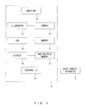
- FIG. 1 is a diagram illustrating the hardware configuration of a biometric authentication apparatus according to the embodiment 1.
- the biometric authentication apparatus 1 is connected to a door control apparatus 2, and performs palm vein authentication.
- the identity check is performed by comparing a registered template that is theveinpatternof apalmregistered in advance with authentication data that is based on a captured vein image.
- the biometric authentication apparatus 1 has a CPU (Central Processing Unit) 10, a memory 11, a non-volatile memory 12, an illuminator 13, a camera 14, an inputter 15, a display 16, an external IF (Interface) 17 as hardware.
- the CPU 10 controls the biometric authentication apparatus 1.
- the memory 11 is a main memory to which the CPU 10 accesses directly.
- the non-volatile memory 12 stores a registered template table, a wide area comparison log table and a search position table described later.
- a hard disc, a flash memory, and the like may be available.
- the illuminator 13 emits near-infrared rays to the palm being a target whose image to be captured by the camera 14.
- a LED and the like may be available.
- the camera 14 receives the near-infrared rays that is emitted from the illuminator 13 and is reflected from the palm to capture an image of the palm vein.
- the inputter 15 is a device by which the user of the biometric authentication apparatus 1 inputs the ID.
- a numerical keypad, a keyboard, a touch panel to input the ID, or a scanning device of a non-contact IC card on which the ID is recorded may be available.
- the display 16 presents information to the user of the biometric authentication apparatus 1.
- the external IF 17 intermediates the transmission/reception of information between the 17 the biometric authentication apparatus 1 the door controller 2.
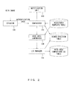
- FIG. 2 is a diagram illustrating the functional configuration of the biometric authentication apparatus according to the embodiment 1.
- FIG. 3 is a diagram illustrating the registered template table.
- FIG. 4 is a diagram illustrating a wide area comparison log table.
- FIG. 5 is a diagram illustrating a search position table.
- the biometric authentication apparatus 1 has an extractor 101, a comparator 102 (comparing unit, presentation unit), a notification unit 103, a wide area comparator 104 (high accuracy comparing unit), a log manager 105 (comparison result storage unit) as the functions.
- the extractor 101 extracts, from a vein image captured by the camera 14, a vein pattern being the biological characteristic used for the biometric authentication as the authentication data.
- the comparator 102 refers to the registered template table, and performs the identity check by comparing the registered template and the authentication data.
- the registered template associates and stores, as illustrated in FIG. 3 , the ID indicating the individual user and the registered template corresponding to the ID.
- the comparator 102 performs, specifically, in the registered template table, a comparison process of the characteristics in the registered template corresponding to the ID input by the inputter 15 and in the authentication data is performed, the degree of similarity indicating the degree of identity between them is calculated, and when the degree of similarity is equal to or above a threshold, it is determined that the user being the authentication target is the subject person.
- the comparator 102 calculates the largest degree of similarity while applying operations such as parallel shift, rotation, contraction and enlargement on a search area specified in advance, and records the search position at which the largest degree of similarity is obtained while associating it with the ID, in the search position table illustrated in FIG. 5 .
- the search area represents the moving area of the authentication data
- the searchposition represents the moved position of the authentication data.
- the notificator 103 sends notification of an instruction for opening a door to the door control apparatus 2 only when the identity check by the comparator 102 is successful.
- the wide area comparator 104 performs the wide area comparison described above, to the authentication with which the identify check by the comparator 102 failed.
- the log manager 105 records the comparison result by the wide area comparator 104 in the wide area comparison log table.
- the wide area comparison log table records, as illustrated in FIG. 4 , associates and stores the log number (No), ID, authentication execution time, comparison result, posture movement.
- the posture movement indicates a position moved with respect to a reference position of the authentication data with which the degree of similarity is equal to or above the threshold in the wide area comparison.
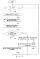
- FIG. 6 is a diagram illustrating the operation of an authentication process in embodiment 1.
- FIG. 7 is a diagram illustrating information attached to error authentication data.
- the extractor 101 determines whether or not an ID has been input to the inputter 15 (S101).
- the comparator 102 executes a message displaying process described later (S102).
- the extractor 101 causes the camera 14 to capture a vein image, and extracts authentication data from the captured image (S103).
- the comparator 102 executes a comparison of the registered template corresponding to the input ID with the registered template table (S104), and determines whether the degree of similarity is above a threshold (S105).
- the search position table when the search position corresponding to the ID exists, it is assumed that the search area of the authentication data in the comparison is based on the search position. In addition, when the search position corresponding to the ID does not exist in the search position table, it is assumed that the search area of the search data in the comparison is an area set in advance.
- step S105 When the degree of similarity is equal or greater than a threshold in step S105 (S105, YES), the comparator 102 records the search position that gave the largest degree of similarity in the search position table (S106). In addition, the notificator 103 sends notification of an instruction for opening the door to the door control apparatus 2 (S107). After the notification, the extractor 101 determines whether or not an ID has been input to the inputter 15 again (S101).
- the comparator 102 records the authentication data as error authentication data, in the memory 11. There, the comparator attaches information illustrated in FIG. 7 to the authentication data.
- the error authentication data includes the authentication data, ID, the authentication execution time, the valid period, the authentication process information.
- the valid period indicates a term to record the error authentication data in the memory 11.
- the authentication process information includes the search area indicating an area searched in the comparison, the largest degree of similarity, and the coordinate position of the authentication at which the degree of similarity becomes largest.
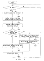
- FIG. 8 is a diagram illustrating operations of a wide area comparison process.
- FIG. 9 is a diagram illustrating the search area.
- FIG. 10 is a diagram illustrating the degree of priority of the search area.
- the wide area comparator 104 determines whether the authentication process is being performed (S201).
- the wide area comparator 104 determines whether error authentication data exists in the memory 11 (S202).
- the wide area comparator 104 conducts the comparison while increasing the search area beyond that in the comparison in the authentication process, as illustrated in FIG. 9 (S203).
- the wide area comparator 104 refers to the authentication process information attached to the authentication data, and excludes the area for which the comparison has already been performed in the authentication process from the search in the wide area comparison.
- the wide area comparator 104 divides the search area into a plurality of blocks as illustrated in FIG. 10 , calculates the distance from a point P at which the degree of similarity in the authentication process is largest to the central point of each block, and expands the search area while giving a higher priority to the block as the distance is smaller.
- the search area is expanded in the order of f, h, i.
- the wide area comparison may be performed efficiently by expanding the search area from around the point at which the degree of similarity is the largest.
- the log manager 105 records the result of the wide area comparison over the expanded search area into the wide area comparison log table with the posture mismatch (S204).
- the log manager 105 records or updates the ID and the corresponding search position in the search position table at the coordinate position at which the degree of similarity becomes largest.
- the log manager 105 deletes the error authentication data for which the wide area comparison has been performed from the memory 11 (S205), and determines whether error authentication data whose valid period has expired exists in the memory 11 (S206).
- the log manager 105 deletes the error authentication data whose valid period has expired from the memory 11 (S207).
- the wide area comparator 104 determines whether the authentication process is being performed again (S201).
- the wide area comparator 104 determines whether the authentication process is being performed again (S201).
- the wide area comparator 104 determines whether the authentication process is being performed again (S201).
- step S201 the wide area comparator 104 determines whether the authentication process is being performed again (S201).
- the biometric authentication apparatus 1 performs the wide area comparison for the error authentication data, and records its result and the posture mismatch as a log. Accordingly, the administrator of the biometric authentication apparatus 1 may investigate the cause of occurrence of the authentication error without retaining authentication data having a problem in security or privacy beyond the valid period.
- FIG. 11 is a diagram illustrating operations of a message display process.
- FIG. 12 is a diagram illustrating a message presented on a display.
- the comparator 102 determines whether a wide area comparison log table corresponding to the input ID exists (S301).
- the comparator 102 determines whether the average of the posture variations in the wide area comparison log table corresponding to the ID is equal to or greater than a predetermined value (S302).
- the comparator 102 determines whether the standard deviation of the posture variations corresponding to the ID is less than a predetermined value (S303). According to this determination, whether the posture variations of the user indicated by the ID have a certain trend.
- the comparator causes the display 16 to display a message for prompting the shift of the hand in the opposite direction to the posture variation direction (S304).
- the shift of the hand of the user may be presented in any way. For example, the user may be prompted to shift the hand by voice.
- the user may be prompted to reregister the registered template. The prompt of the reregistration of the registered template may be sent to the administrator and the like of the biometric authentication apparatus 1 via a connected network.
- the authentication error caused by the mismatch of the hand position in the authentication may be reduced.
- the biometric authentication apparatus performs palm vein authentication, while in embodiment 2, the biometric authentication apparatus performs face authentication as the biometric authentication.
- the biometric authentication apparatus according to the embodiment 2 is explained.
- the biometric authentication apparatus 1 according to the embodiment 2 is connected to the door control apparatus 2 and performs face authentication.
- face authentication the identity check is performed by comparing a pattern (registered template) representing the characteristics of a face registered in advance and authentication data based on a face image captured.
- the non-volatile memory 12 stores the registered template table, the wide area comparison log table, the search position table, as well as a partial comparison log table, an illumination intensityadjustment table, a user-specific external error table, an error factor table, and an external light error rate table.
- the illuminator 13 radiates white light toward the face of the user being the image capturing target of the camera 14.
- the camera 14 captures the image of the face irradiated with white light radiated by the illuminator 13.
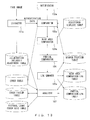
- FIG. 13 is a diagram illustrating the functional configuration of the biometric authentication apparatus according to the embodiment 2.
- FIG. 14 is a diagram illustrating a partial comparison log table.
- FIG. 15 is a diagram illustrating an error table.
- FIG. 16 is a diagram illustrating an error factor table.
- FIG. 17 is a diagram illustrating an illumination intensity table.
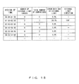
- FIG. 18 is a diagram illustrating an external light error rate table.
- the biometric authentication apparatus 1 has functionally an extractor 101a, a comparator 102a (comparing unit), notificator 103a, a wide area comparator 104a (high accuracy comparing unit), a log manager 105a (comparison result storage unit), a partial comparator 106 (high accuracy comparing unit), an analyzer 107.
- the extractor 101a causes the camera 14 to capture a face image, and extracts authentication data from the face image.
- the extractor 101a adjust the illumination intensity by the illuminator 13 based on an illumination intensity adjustment table in capturing the image.
- the comparator 102a refers to the registered template table, performs the identity check by comparing the registered template with the authentication data, and based on its result, updates the error table.
- the error table records, as illustrated in FIG. 15 , the combination of the ID and the period of time and the number of times of comparing and the number of errors.
- the notificator 103a sends notification of an instruction for opening a door to the door control apparatus 2 only when the identity check by the comparator 102a is successful.
- the wide area comparator 104a performs the wide area comparison described above, to the authentication with which the identify check by the comparator 102a failed.
- the partial comparator 106 performs partial comparison described later, to the authentication with which the identify check by the comparator 102a failed.
- the log manager 105a records the comparison result by the wide area comparator 104a in the wide area comparison log table, and records the comparison result by the partial comparator 106 in the partial comparison log table.
- the log number (No) the ID, the authentication execution time, the comparison result, the comparisonblock, and the external light direction are associated with each other and recorded. Meanwhile, the comparison block and the external light direction are described later.
- the analyzer 107 performs analysis based on at least one of the error table, the wide area comparison log table, and the partial comparison log table, and updates the illumination intensity adjustment table, the error factor table, and the external light error rate table.
- the error factor table as illustrated in FIG.
- the ID and the period of time, and each of the numbers of times of factors of the authentication are associated with each other and recorded.
- the illumination intensity adjustment table the period of time and the illumination intensity of the illuminator 13 are associated with each other and recorded.
- the illumination intensity is indicated by the duty ratio of the PWM (Pulse Width Modulation), for example.
- the external light error rate table as illustrated in FIG. 18 , the period of time, the number of external light errors, the total number of matching, the error rate due to external light and the external light direction are associated with each other and recorded.
- the error rate due to external light represents the ratio of the number of errors due to external light to the total number of times of comparing by all users who perform authentication in the corresponding period of time.
- the external direction represents the average value of all the external light directions calculated by the partial comparison of the error authentication data in the corresponding period of time.
- FIG. 19 is a diagram illustrating operations of an authentication process in the embodiment 2.
- the extractor 101a determines whether an ID has been input to the inputter 15 (S401).
- the extractor 101a When an ID has been input to the inputter 15 (S401, YES), the extractor 101a causes the illuminator 13 to adjust the illumination intensity to that corresponding to the current period of time in the illumination intensity adjustment table (S402). Next, the extractor 101a causes the camera 14 to capture a face image, and extracts an authentication data from the captured image (S403). Next, the comparator 102a performs comparing the registered template corresponding to the input ID in the registered template table and the authentication data (S404), and determines whether the degree of similarity is equal to or greater then a threshold (S405). Here, the comparator 102a refers to the search position table in a similar manner to the comparator 102 in the embodiment 1.
- the comparator 102a When the degree of similarity is less than the threshold (S405, NO), the comparator 102a records the authentication data as error authentication data in the memory 11 (S406), and updates the error table (S407). In this case, the comparator 102a increments the total number of comparisons and the number of errors corresponding to the ID. After the update of the error table, the extractor 101a determines whether an ID has been input to the inputter 15 again (S401).
- the comparator 102a records the search position that gave the largest degree of similarity in the search position table (S408).
- the notificator 103a sends a notification of an instruction for opening a door to the comparator 102a (S409).
- the comparator 102a increments only the total number of comparisons corresponding to the ID.
- the extractor 101a determines whether an ID has been input to the inputter 15 again (S401).
- the high accuracy comparison process is a process to perform partial comparison in addition to the wide area comparison explained in the embodiment 1.
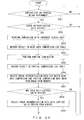
- FIG. 20 is a flowchart illustrating the operations of a high accuracy comparison process.
- FIG. 21 is a diagram illustrating blocks divided in the partial comparison.
- FIG. 22 is a diagram illustrating an effect of the partial comparison.
- FIG. 23 is a diagram illustrating the formula to obtain the external light direction.
- FIG. 24 is a diagram schematically illustrating the way to obtain the external light direction.
- FIG. 25 is a diagram illustrating the angle of the external light direction.
- the wide area comparator 104a determines whether the authentication process is being performed (S501).
- the wide area comparator 104a determines whether error authentication data exists in the memory 11 (S502).
- the wide area comparator 104a When error authentication data exists in the memory 11 (S502, YES), the wide area comparator 104a conducts the comparison while enlarging the search area beyond that in the comparison in the authentication process (S503). After the execution of the wide area comparison, the log manager 105a records the result of the wide area comparison over an expanded search area in the wide area comparison log table with the posture mismatch (S504).
- the partial comparator 106 executes partial comparison on the error authentication data (S505).
- the partial comparison is explained.
- the authentication data is divided into a plurality of blocks, and comparison with the registered template is performed for each of the blocks.
- the authentication data is divided into four blocks of a, b, c, d.
- the comparison can be performed with blocks without the lack.
- the partial comparator 106 estimates the external light direction representing the incident direction of external light in a captured image.
- the external light direction is a direction with respect to the center of the error authentication data at a position at which the degree of similarity is lowest in the authentication data.
- the vector A representing the external direction is obtained by the formula presented in FIG. 23 .
- the external light direction is obtained.
- the weight is a value represented by the reciprocal of the degree of similarity for each block.
- the light-dark tone for each block represents the degree of similarity, and the darker block means the lower the degree of similarity and the lighter block means the higher the degree of similarity.
- the external light direction estimated as described above is supposed to be expressed by the clockwise angle with respect to the center of the error authentication data as illustrated in FIG. 25 .
- the partial comparator 106 calculates the average luminance of the block with the lowest degree of similarity in the partial comparison and records the value in non-volatile memory 12 while associating it with the time zone in which the comparison is performed.
- the log manager 105a After the execution of the partial comparison, the log manager 105a records the result of the wide area comparison with an expanded search area in the wide area comparison log table with the posture mismatch (S504).
- the block with a degree of similarity equal to or greater than the threshold and the external light direction estimated in the method described above are associated with the ID and recorded in the search position table.
- the log manager 105a deletes the error authentication data for which the wide area comparison and the partial comparison have been performed from the memory 11 (S507), and determines whether error authentication data whose valid period has expired exists in the memory 11 (S508).
- the log manager 105a deletes the error authentication data whose valid period has expired from the memory 11 (S509).
- the wide area comparator 104a determines whether the authentication process is being performed again (S501).
- the wide area comparator 104a determines whether the authentication process is being performed again (S501).
- the wide area comparator 104a determines whether the authentication process is being performed again (S501).
- step S501 the wide area comparator 104a determines whether the authentication process is being performed again (S501).
- the biometric authentication apparatus 1 performs the partial area comparison on the error authentication data, and records its result and the external light direction as a log. Accordingly, the administrator of the biometric authentication apparatus 1 may investigates the cause of occurrence of the authentication error without leaving authentication data having an issue in terms of security or privacy beyond the valid period. In addition, by performing the wide area comparison and the partial comparison to the same error authentication data, the administrator may identify the cause of the occurrence of the authentication error from the group of posture mismatch, external light, and both of posture mismatch and external light.
- the analysis process is a process to perform analysis based on the result of the wide area comparison and the partial comparison.
- FIG. 26 is a diagram illustrating the operations of the analysis process.
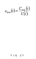
- FIG. 27 is a diagram illustrating the formula to calculate an error rate due to external light.
- FIG. 28 is a diagram illustrating the formula to calculate the average vector of the external light directions.
- the analyzer 107 determines whether a predetermined time set in advance has elapsed (S601).
- the analyzer 107 determines whether the authentication process is being executed (S602).
- the analyzer 107 determines whether the high accuracy comparison process is being processed (S603).
- the analyzer 107 updates the error factor table, based on the error table, the wide area comparison table and the partial comparison log table (S604).
- the analyzer 107 calculates the error rate due to external light for each period of time, based on the error factor table (S605).
- the error rate due to external light is obtained by the formula presented in FIG. 27 assuming the period of time as t, the error rate due to external light in the period of time t as e ErrL (t), the total number of comparison in the period of time t as C(t), the number of errors due to external light in the period of time t as C ErrL (t).
- t is assumed as a variable that represents 00:00 ⁇ 23:00 by values 0 ⁇ 23.
- the analyzer 107 calculates the average vector of the external directions based on the partial comparison log table (S606).
- the average vector is obtained by the formula presented in FIG. 2 8 , assuming the period of time as t, the average vector in the period of time t as vector ⁇ A>, the variable representing each external light error in the period of time t as i, the vector in the external error i as vector Ai, the number of errors due to external light in the period of time t as C ErrL (t).
- the analyzer 107 updates the external light error rate table based on these calculated values (S607).
- the analyzer 107 calculates the illumination intensity, based on the average luminance value associated with the ID of the user whose number of external light error is equal to or greater than a predetermined number in the error factor table and that is not recorded in the illumination intensity table (S608).
- the average luminance value is the value calculated by the partial comparator 106 in the partial comparison described above.
- the analyzer 107 calculates the illumination intensity, based on the correspondence relationship between the average luminance value and the appropriate illumination intensity.
- the correspondence relationship is supposed to have been obtained in advance by capturing the image of a face such that external light is included in a predetermined block i and adjusting the illumination intensity of the illuminator 13 so that the average illumination value of the block i in the authentication data based on the face image becomes a suitable value.
- the analyzer 107 updates the illumination intensity table of the period of time associated with the average illumination value (S609). After the update, the analyzer 107 determines whether the predetermined time has elapsed again (S601).
- step S603 when the high accuracy comparison is being performed (S603, YES), the analyzer 107 determines whether the authentication process is being performed again (S602).
- step S602 when the authentication process is being executed (S602, YES), the analyzer 107 whether the predetermined time has elapsed again (S601).
- step S601 when the predetermined time does not have elapsed (S601, NO), the analyzer 107 determines whether the predetermined time has elapsed again (S601).
- biometric authentication apparatus 1 performing analysis based on the error table, wide area comparison log table, partial comparison log table, the burden on the administrator of the biometric authentication apparatus 1 may be reduced. For example, with the biometric authentication apparatus 1 sending a notification mail to the administrator via a network, the administrator does not need to regularly monitor the log data of the biometric authentication apparatus 1.
- FIG. 29 is a diagram illustrating the formula to calculate an external light error generating user rate.
- the number of external light error generating users is calculated by the formula presented in FIG. 29 assuming the period of time as t, the rate of users for whom an error due to external light occurs in the period of time t as e' ErrL (t), the number of users for whom the comparison is performed in the period of time t as N(t), the number of users for whom an error due to external light occurs in the period of time t N ErrL (t).
- the external light error generating user rate is especially effective in a case such as when a particular user generates a number of errors and increases the overall external light error rate. For example, when the external light error generating user rate corresponding to the period of time over which the external error rate is high is high, the administrator may predict that the external light errors are occurring not just for a particular user. That is, by referring to the external lighterrorgeneratinguserrate, theadministratormaydetermine the degree of reliability of the external light error rate.
- FIG. 30 is a diagram illustrating a history table.
- the history table associates and records the date, the number of external errors per day, the total number of matching per day, the error rate due to external light per day, and the average of the external light directions per day.
- the history table is created for each period of time.
- the analyzer 107 updates the history table of the period of time in which the comparison is performed, for every comparison.
- the history table for each period of time is supposed to be linked to the corresponding period of time in the external light error rat table.
- the analyzer 107 may calculate the error rate due to posture mismatch for each user.
- FIG. 31 is a diagram illustrating an error rate due to posture mismatch.
- FIG. 32 is a diagram illustrating the change in the error rate due to external light.
- the error rate due to the posture mismatch is calculated by the formula presented in FIG. 31 assuming the period of time as t, the error rate due to the posture mismatch for a particular user as e A , the total number of comparison for the particular user in the period of time t as C(t), the total number of errors due to the posture of the particular user as C ErrA (t).
- the analyzer 107 may calculate the error rate due to external light for top 5% users with a low error rate due to the posture mismatch.
- the administrator may obtain the change in the external light error rate illustrated in FIG. 32 .
- the vertical axis represents the error rate due to external light
- the horizontal axis represents the time. With the change in the external light error rate, the administrator may predict the period of time over which external light affects the comparison more accurately.
- FIG. 33 is a diagram illustrating the formula for calculating a factor unknown error rate.
- the factor unknown error rate e* AL (t) in the period of time t is calculated by the formula presented in Fig. 33 assuming the period of time as t, the total number of comparisons during the time t as C(t). the total number of errors in the period of time (t) as CErr(t), the total number of errors due to the posture mismatch in the period of time t as C ErrA (t), and the total number of errors due to external light as C ErrL (t).
- the biometric authentication apparatus 1 sends a notification to the administrator by mail with a higher priority than that for errors due to other factors. Accordingly, the administrator may cope with an error with an unknown cause promptly.
- the administrator may estimate the cause of an error without saving the error authentication data.
- comparison such as the wide area comparison and the partial comparison with a higher accuracy than the normal comparison and recording their results.
- the administrator may estimate the cause of an error without saving the error authentication data.
- the two embodiments described above may be combined and implemented.
- FIG. 34 is a diagram illustrating an example of a computer system.
- the computer system 900 illustrated in FIG. 34 has a main unit 901 including built-in CPU, disc drive and the like, a display 902 that displays an image in response to an instruction from the main unit 901, a keyboard 903 for inputting various information to the computer system 900, a mouse 904 that specifies an arbitrary position on a display screen 902a on the display 902, and a communication apparatus 905 that accesses an external database and the like and downloads a program and the like stored in another computer system.
- the communication apparatus 905 a network communication card, modem (modulator-demodulator) are available.
- a program for causing the computer system as described above to execute each step described above may be provided as a biometric authentication program.
- the program can be stored in a recording medium readable by the computer system to be executed by the computer system constituting a biometric authentication apparatus.
- the program processing each step described above may be stored in a portable recording medium such as a disc 910 and the like, or may be downloaded from a recording medium 906 of another computer system by the communication apparatus 905.
- the biometric authentication program that realizes at least the biometric authentication function in the computer system 900 is loaded into and compiled by the computer system 900.
- the program causes the computer system 900 to operate as a biometric authentication apparatus having a biometric authentication function.
- this program may be stored in a computer readable recording medium such as the disc 910.
- the recording medium readable by the computer system 900 includes an internal storage apparatus implemented inside the computer such as ROM and RAM, a portable recording medium such as the disc 910, a flexible disc, DVD disc, magnet-optical disc, IC card and the like, a database that holds a computer program, or, another computer or its data base, and various recording media accessible by a computer system connected via communication means such as the communication apparatus 905.
- an internal storage apparatus implemented inside the computer such as ROM and RAM
- a portable recording medium such as the disc 910, a flexible disc, DVD disc, magnet-optical disc, IC card and the like
- a database that holds a computer program
- another computer or its data base such as the communication apparatus 905.
- 1 biometric authentication apparatus 2 door control apparatus , 10 CPU, 11 memory, 12 non-volatile memory , 13 illuminator , 14 camera, 15 inputter, 16 display, 17 external IF, 101,101a extractor , 102,102a comparator , 103,103a notificator , 104,104a wide area comparator , 105,105a log manager , 106 partial comparator , 107 analyzer
Landscapes
- Engineering & Computer Science (AREA)
- Computer Security & Cryptography (AREA)
- Theoretical Computer Science (AREA)
- Physics & Mathematics (AREA)
- General Physics & Mathematics (AREA)
- Biodiversity & Conservation Biology (AREA)
- Computer Hardware Design (AREA)
- Software Systems (AREA)
- General Engineering & Computer Science (AREA)
- Health & Medical Sciences (AREA)
- Life Sciences & Earth Sciences (AREA)
- Biomedical Technology (AREA)
- General Health & Medical Sciences (AREA)
- Computer Networks & Wireless Communication (AREA)
- Signal Processing (AREA)
- Multimedia (AREA)
- Human Computer Interaction (AREA)
- Collating Specific Patterns (AREA)
Abstract
Description
- The present invention relates to a biometric authentication apparatus, a biometric authentication program and method.
- Biometric authentication has been known as a technique to identify an individual person based on biological characteristics which is possessed by a human being, such as the vein pattern, the face pattern and the like. In the biometric authentication, first, data representing the biological characteristics of an authentication target is registered as a registered template, and the subject person is identified by comparing authentication data representing characteristics of the biological pattern of an individual person obtained by a sensor such as a camera with the registered template in the authentication. Specifically, the degree of similarity between the authentication data and the registered template is calculated, and when the degree of similarity exceeds a predetermined threshold, the authentication target is determined as the subject person. In such biometric authentication, the authentication errors occur at a certain rate. As one of the authentication errors, there is a false rejection error by which, even though a characteristic data indicates the subject person, identity verification may fail due to a low degree of similarity of the characteristic data with the registered template.
- There are mainly two possible reasons for the authentication errors described above. One reason is ascribed to the posture mismatch of the authentication part with the direction of the sensor used to the authentication. Since the subject of the authentication is a human being, the authentication part is not necessarily captured by the sensor when a posture of the authentication part matches with the posture in the registered template. Another reason is ascribed to an external light on the biometric authentication apparatus. The biometric authentication using an image is sometimes affected by the sunlight from outside, indoor incandescent lights and the like. Whilemanyof the authenticationapparatuses illuminate the subject using a light source provided for themselves and capture the image, when the amount of unintended light from the sunlight and incandescent lights has a large influence on the image, these external lights cause an authentication error.
-
- Patent Document 1: Japanese Laid-open Patent Publication No.
2007-257040 - Patent Document 2: Japanese Laid-open Patent Publication No.
2009-009434 - Patent Document 2: Japanese Laid-open Patent Publication No.
2005-071009 - Patent Document 2: Japanese Laid-open Patent Publication No.
H02-158841 - However, since it is difficult to save authentication data including data of the face and veins of a person to be authenticated as a log due to security and privacy issues, it is difficult for the administrator of the biometric authentication apparatus to investigate the cause of the occurrence of an authentication error.
- The present invention has been made to solve the problem described above, with an objective of providing a biometric authentication apparatus, a biometric authentication program and method that makes it possible to investigate the cause of the occurrence of an authentication error without saving authentication data as a log.
- In order to solve the problem described above, a biometric authentication apparatus has a comparator that performs authentication of the user by comparing biological information read from a user with registered biological information registered in a storage in advance; a high accuracy comparator that compares the biological information and the registered biological information with a higher accuracy than the comparison by the comparator when the user is not authenticated by the comparator; and a comparison result storage that records a comparison result obtained by the high accuracy comparator in the storage.
- The cause of the occurrence of an authentication error can be investigated without saving authentication data as a log.
-
-
FIG. 1 is a diagram illustrating the hardware configuration of a biometric authentication apparatus according toembodiment 1. -
FIG. 2 is a diagram illustrating the functional configuration of the biometric authentication apparatus according toembodiment 1. -
FIG. 3 is a diagram illustrating a registered template table. -
FIG. 4 is a diagram illustrating a wide area comparison log table. -
FIG. 5 is a diagram illustrating the search position table. -
FIG. 6 is a diagram illustrating operations of an authentication process inembodiment 1. -
FIG. 7 is a diagram illustrating information attached to error authentication data. -
FIG. 8 is a diagram illustrating operations of a wide area comparison process. -
FIG. 9 is a diagram illustrating a search area. -
FIG. 10 is a diagram illustrating the degree of priority of the search area. -
FIG. 11 is a diagram illustrating operations of a message display process. -
FIG. 12 is a diagram illustrating a message presented on a display. -
FIG. 13 is a diagram illustrating the functional configuration of the biometric authentication apparatus according toembodiment 2. -
FIG. 14 is a diagram illustrating a partial comparison log table. -
FIG. 15 is a diagram illustrating an error table. -
FIG. 16 is a diagram illustrating an error factor table. -
FIG. 17 is a diagram illustrating an illumination intensity table. -
FIG. 18 is a diagram illustrating an external light error rate table. -
FIG. 19 is a diagram illustrating operations of an authentication process inembodiment 2. -
FIG. 20 is a flowchart illustrating operations of a high accuracy comparison process. -
FIG. 21 is a diagram illustrating blocks divided in the partial comparison. -
FIG. 22 is a diagram illustrating an effect of the partial comparison. -
FIG. 23 is a diagram illustrating the formula for obtaining the external light direction. -
FIG. 24 is a diagram schematically illustrating a method for obtaining the external light direction. -
FIG. 25 is a diagram illustrating the angle of the external light direction. -
FIG. 26 is a diagram illustrating operations of an analysis process. -
FIG. 27 is a diagram illustrating the formula for calculating an error rate due to external light. -
FIG. 28 is a diagram illustrating the formula for calculating the average vector of the external light directions. -
FIG. 29 is a diagram illustrating the formula for calculating an external error generating user rate. -
FIG. 30 is a diagram illustrating a history table. -
FIG. 31 is a diagram illustrating an error rate due to posture mismatch. -
FIG. 32 is a diagram illustrating the change in the error rate due to external light. -
FIG. 33 is a diagram illustrating the formula for calculating a cause unknown error rate. -
FIG. 34 is a diagram illustrating an example of a computer system. - Hereinafter, embodiments of the present invention are explained referring to the drawings.
- First, the hardware configuration of a biometric authentication apparatus according to an
embodiment 1 is explained.FIG. 1 is a diagram illustrating the hardware configuration of a biometric authentication apparatus according to theembodiment 1. - The
biometric authentication apparatus 1 according to theembodiment 1 is connected to adoor control apparatus 2, and performs palm vein authentication. In the palm vein authentication, the identity check is performed by comparing a registered template that is theveinpatternof apalmregistered in advance with authentication data that is based on a captured vein image. As illustrated inFIG. 1 , thebiometric authentication apparatus 1 has a CPU (Central Processing Unit) 10, amemory 11, anon-volatile memory 12, anilluminator 13, acamera 14, aninputter 15, adisplay 16, an external IF (Interface) 17 as hardware. TheCPU 10 controls thebiometric authentication apparatus 1. Thememory 11 is a main memory to which theCPU 10 accesses directly. Thenon-volatile memory 12 stores a registered template table, a wide area comparison log table and a search position table described later. As thenon-volatile memory 12, a hard disc, a flash memory, and the like may be available. Theilluminator 13 emits near-infrared rays to the palm being a target whose image to be captured by thecamera 14. As theilluminator 13, a LED and the like may be available. Thecamera 14 receives the near-infrared rays that is emitted from theilluminator 13 and is reflected from the palm to capture an image of the palm vein. As thecamera 14, a CMOS (Complementary Metal Oxide Semiconductor) image sensor, and a CCD (Charge Coupled Device) may be available. Theinputter 15 is a device by which the user of thebiometric authentication apparatus 1 inputs the ID. As theinputter 15, a numerical keypad, a keyboard, a touch panel to input the ID, or a scanning device of a non-contact IC card on which the ID is recorded may be available. Thedisplay 16 presents information to the user of thebiometric authentication apparatus 1. The external IF 17 intermediates the transmission/reception of information between the 17 thebiometric authentication apparatus 1 thedoor controller 2. - Next, the functional configuration of the biometric authentication apparatus according to the
embodiment 1 is explained.FIG. 2 is a diagram illustrating the functional configuration of the biometric authentication apparatus according to theembodiment 1. Meanwhile,FIG. 3 is a diagram illustrating the registered template table. Meanwhile,FIG. 4 is a diagram illustrating a wide area comparison log table.FIG. 5 is a diagram illustrating a search position table. - As illustrated in
FIG. 2 , thebiometric authentication apparatus 1 has anextractor 101, a comparator 102 (comparing unit, presentation unit), anotification unit 103, a wide area comparator 104 (high accuracy comparing unit), a log manager 105 (comparison result storage unit) as the functions. Theextractor 101 extracts, from a vein image captured by thecamera 14, a vein pattern being the biological characteristic used for the biometric authentication as the authentication data. Thecomparator 102 refers to the registered template table, and performs the identity check by comparing the registered template and the authentication data. The registered template associates and stores, as illustrated inFIG. 3 , the ID indicating the individual user and the registered template corresponding to the ID. Thecomparator 102 performs, specifically, in the registered template table, a comparison process of the characteristics in the registered template corresponding to the ID input by theinputter 15 and in the authentication data is performed, the degree of similarity indicating the degree of identity between them is calculated, and when the degree of similarity is equal to or above a threshold, it is determined that the user being the authentication target is the subject person. In addition, thecomparator 102 calculates the largest degree of similarity while applying operations such as parallel shift, rotation, contraction and enlargement on a search area specified in advance, and records the search position at which the largest degree of similarity is obtained while associating it with the ID, in the search position table illustrated inFIG. 5 . Here, the search area represents the moving area of the authentication data, and the searchposition represents the moved position of the authentication data. Thenotificator 103 sends notification of an instruction for opening a door to thedoor control apparatus 2 only when the identity check by thecomparator 102 is successful. Thewide area comparator 104 performs the wide area comparison described above, to the authentication with which the identify check by thecomparator 102 failed. Thelog manager 105 records the comparison result by thewide area comparator 104 in the wide area comparison log table. The wide area comparison log table records, as illustrated inFIG. 4 , associates and stores the log number (No), ID, authentication execution time, comparison result, posture movement. Here, the posture movement indicates a position moved with respect to a reference position of the authentication data with which the degree of similarity is equal to or above the threshold in the wide area comparison. - Next, the authentication process in
embodiment 1 is explained.FIG. 6 is a diagram illustrating the operation of an authentication process inembodiment 1.FIG. 7 is a diagram illustrating information attached to error authentication data. - As illustrated in
FIG. 6 , first, theextractor 101 determines whether or not an ID has been input to the inputter 15 (S101). - When the ID has been input to the inputter 15 (S101, YES), the
comparator 102 executes a message displaying process described later (S102). Next, theextractor 101 causes thecamera 14 to capture a vein image, and extracts authentication data from the captured image (S103). Next, thecomparator 102 executes a comparison of the registered template corresponding to the input ID with the registered template table (S104), and determines whether the degree of similarity is above a threshold (S105). Meanwhile, in the search position table, when the search position corresponding to the ID exists, it is assumed that the search area of the authentication data in the comparison is based on the search position. In addition, when the search position corresponding to the ID does not exist in the search position table, it is assumed that the search area of the search data in the comparison is an area set in advance. - When the degree of similarity is equal or greater than a threshold in step S105 (S105, YES), the
comparator 102 records the search position that gave the largest degree of similarity in the search position table (S106). In addition, thenotificator 103 sends notification of an instruction for opening the door to the door control apparatus 2 (S107). After the notification, theextractor 101 determines whether or not an ID has been input to theinputter 15 again (S101). - On the other hand, when the degree of similarity is less than the threshold (S105, NO), the
comparator 102 records the authentication data as error authentication data, in thememory 11. There, the comparator attaches information illustrated inFIG. 7 to the authentication data. The error authentication data includes the authentication data, ID, the authentication execution time, the valid period, the authentication process information. Here, the valid period indicates a term to record the error authentication data in thememory 11. In addition, the authentication process information includes the search area indicating an area searched in the comparison, the largest degree of similarity, and the coordinate position of the authentication at which the degree of similarity becomes largest. After recording the error authentication data, theextractor 101 determines whether an ID has been input to theinputter 15 again (S101). - Next, the operation of a wide area comparison process is explained.
FIG. 8 is a diagram illustrating operations of a wide area comparison process. Meanwhile,FIG. 9 is a diagram illustrating the search area. Meanwhile,FIG. 10 is a diagram illustrating the degree of priority of the search area. - As illustrated in
FIG. 8 , first, thewide area comparator 104 determines whether the authentication process is being performed (S201). - When the authentication process is not being performed (5201, NO), the
wide area comparator 104 determines whether error authentication data exists in the memory 11 (S202). - When error authentication data exists in the memory 11 (S202, YES), the
wide area comparator 104 conducts the comparison while increasing the search area beyond that in the comparison in the authentication process, as illustrated inFIG. 9 (S203). At this process, thewide area comparator 104 refers to the authentication process information attached to the authentication data, and excludes the area for which the comparison has already been performed in the authentication process from the search in the wide area comparison. In addition, thewide area comparator 104 divides the search area into a plurality of blocks as illustrated inFIG. 10 , calculates the distance from a point P at which the degree of similarity in the authentication process is largest to the central point of each block, and expands the search area while giving a higher priority to the block as the distance is smaller. InFIG. 10 , the search area is expanded in the order of f, h, i. As described above, the wide area comparison may be performed efficiently by expanding the search area from around the point at which the degree of similarity is the largest. - Next, the
log manager 105 records the result of the wide area comparison over the expanded search area into the wide area comparison log table with the posture mismatch (S204). Here, when the degree of similarity in the wide area comparison is equal to or greater than a threshold, thelog manager 105 records or updates the ID and the corresponding search position in the search position table at the coordinate position at which the degree of similarity becomes largest. - Next, the
log manager 105 deletes the error authentication data for which the wide area comparison has been performed from the memory 11 (S205), and determines whether error authentication data whose valid period has expired exists in the memory 11 (S206). - When error authentication data whose valid period has expired exists in the memory 11 (S206, YES), the
log manager 105 deletes the error authentication data whose valid period has expired from the memory 11 (S207). Next, thewide area comparator 104 determines whether the authentication process is being performed again (S201). - On the other hand, when error authentication data whose valid period has expired does not exist in the memory 11 (S206, NO), the
wide area comparator 104 determines whether the authentication process is being performed again (S201). - Meanwhile, when there is no error authentication data in the memory 11 (S202, NO), the
wide area comparator 104 determines whether the authentication process is being performed again (S201). - Meanwhile, when the authentication process is being performed in step S201 (S201, YES), the
wide area comparator 104 determines whether the authentication process is being performed again (S201). - Thus, the
biometric authentication apparatus 1 according toembodiment 1 performs the wide area comparison for the error authentication data, and records its result and the posture mismatch as a log. Accordingly, the administrator of thebiometric authentication apparatus 1 may investigate the cause of occurrence of the authentication error without retaining authentication data having a problem in security or privacy beyond the valid period. - Next, the operation of a message display process is explained.
FIG. 11 is a diagram illustrating operations of a message display process. Meanwhile,FIG. 12 is a diagram illustrating a message presented on a display. - As illustrated in
FIG. 11 , first, thecomparator 102 determines whether a wide area comparison log table corresponding to the input ID exists (S301). - If a wide area comparison log table corresponding to the input ID exists (S301, YES), the
comparator 102 determines whether the average of the posture variations in the wide area comparison log table corresponding to the ID is equal to or greater than a predetermined value (S302). - When the average of the posture variations in the wide area comparison log table corresponding to the ID is equal to or greater than a predetermined value (S302, YES), the
comparator 102 determines whether the standard deviation of the posture variations corresponding to the ID is less than a predetermined value (S303). According to this determination, whether the posture variations of the user indicated by the ID have a certain trend. - When the standard deviation of the posture variations corresponding to the ID is less than a predetermined value, as illustrated in
FIG. 12 , the comparator causes thedisplay 16 to display a message for prompting the shift of the hand in the opposite direction to the posture variation direction (S304). Meanwhile, the shift of the hand of the user may be presented in any way. For example, the user may be prompted to shift the hand by voice. In addition, if the amount of the posture variation exceeds a predetermined range, the user may be prompted to reregister the registered template. The prompt of the reregistration of the registered template may be sent to the administrator and the like of thebiometric authentication apparatus 1 via a connected network. - Thus, by presenting a message to the user based on the posture variations in the wide area comparison log table, the authentication error caused by the mismatch of the hand position in the authentication may be reduced.
- In the
embodiment 1 described above, the biometric authentication apparatus performs palm vein authentication, while inembodiment 2, the biometric authentication apparatus performs face authentication as the biometric authentication. Hereinafter, the biometric authentication apparatus according to theembodiment 2 is explained. - First, regarding the hardware configuration of the
biometric authentication apparatus 1 according to theembodiment 2, the difference from theembodiment 1 is explained. Thebiometric authentication apparatus 1 according to theembodiment 2 is connected to thedoor control apparatus 2 and performs face authentication. In the face authentication, the identity check is performed by comparing a pattern (registered template) representing the characteristics of a face registered in advance and authentication data based on a face image captured. Thenon-volatile memory 12 stores the registered template table, the wide area comparison log table, the search position table, as well as a partial comparison log table, an illumination intensityadjustment table, a user-specific external error table, an error factor table, and an external light error rate table. Theilluminator 13 radiates white light toward the face of the user being the image capturing target of thecamera 14. Thecamera 14 captures the image of the face irradiated with white light radiated by theilluminator 13. - Next, the functional configuration of the
biometric authentication apparatus 1 according to theembodiment 2 is explained.FIG. 13 is a diagram illustrating the functional configuration of the biometric authentication apparatus according to theembodiment 2. Meanwhile,FIG. 14 is a diagram illustrating a partial comparison log table. Meanwhile,FIG. 15 is a diagram illustrating an error table. Meanwhile,FIG. 16 is a diagram illustrating an error factor table. Meanwhile,FIG. 17 is a diagram illustrating an illumination intensity table. Meanwhile,FIG. 18 is a diagram illustrating an external light error rate table. - As illustrated in
FIG. 13 , thebiometric authentication apparatus 1 according to theembodiment 2 has functionally anextractor 101a, acomparator 102a (comparing unit), notificator 103a, awide area comparator 104a (high accuracy comparing unit), alog manager 105a (comparison result storage unit), a partial comparator 106 (high accuracy comparing unit), ananalyzer 107. Theextractor 101a causes thecamera 14 to capture a face image, and extracts authentication data from the face image. In addition, theextractor 101a adjust the illumination intensity by theilluminator 13 based on an illumination intensity adjustment table in capturing the image. Thecomparator 102a refers to the registered template table, performs the identity check by comparing the registered template with the authentication data, and based on its result, updates the error table. The error table records, as illustrated inFIG. 15 , the combination of the ID and the period of time and the number of times of comparing and the number of errors. Thenotificator 103a sends notification of an instruction for opening a door to thedoor control apparatus 2 only when the identity check by thecomparator 102a is successful. Thewide area comparator 104a performs the wide area comparison described above, to the authentication with which the identify check by thecomparator 102a failed. Thepartial comparator 106 performs partial comparison described later, to the authentication with which the identify check by thecomparator 102a failed. Thelog manager 105a records the comparison result by thewide area comparator 104a in the wide area comparison log table, and records the comparison result by thepartial comparator 106 in the partial comparison log table. In the partial comparison log table, as illustrated inFIG. 14 , the log number (No), the ID, the authentication execution time, the comparison result, the comparisonblock, and the external light direction are associated with each other and recorded. Meanwhile, the comparison block and the external light direction are described later. Theanalyzer 107 performs analysis based on at least one of the error table, the wide area comparison log table, and the partial comparison log table, and updates the illumination intensity adjustment table, the error factor table, and the external light error rate table. In the error factor table, as illustrated inFIG. 16 , the ID and the period of time, and each of the numbers of times of factors of the authentication are associated with each other and recorded. Meanwhile, in the illumination intensity adjustment table, the period of time and the illumination intensity of theilluminator 13 are associated with each other and recorded. The illumination intensity is indicated by the duty ratio of the PWM (Pulse Width Modulation), for example. Meanwhile, in the external light error rate table, as illustrated inFIG. 18 , the period of time, the number of external light errors, the total number of matching, the error rate due to external light and the external light direction are associated with each other and recorded. The error rate due to external light represents the ratio of the number of errors due to external light to the total number of times of comparing by all users who perform authentication in the corresponding period of time. Meanwhile, the external direction represents the average value of all the external light directions calculated by the partial comparison of the error authentication data in the corresponding period of time. - Next, the authentication process in the
embodiment 2 is explained.FIG. 19 is a diagram illustrating operations of an authentication process in theembodiment 2. - As illustrated in
FIG. 19 , first, theextractor 101a determines whether an ID has been input to the inputter 15 (S401). - When an ID has been input to the inputter 15 (S401, YES), the
extractor 101a causes theilluminator 13 to adjust the illumination intensity to that corresponding to the current period of time in the illumination intensity adjustment table (S402). Next, theextractor 101a causes thecamera 14 to capture a face image, and extracts an authentication data from the captured image (S403). Next, thecomparator 102a performs comparing the registered template corresponding to the input ID in the registered template table and the authentication data (S404), and determines whether the degree of similarity is equal to or greater then a threshold (S405). Here, thecomparator 102a refers to the search position table in a similar manner to thecomparator 102 in theembodiment 1. - When the degree of similarity is less than the threshold (S405, NO), the
comparator 102a records the authentication data as error authentication data in the memory 11 (S406), and updates the error table (S407). In this case, thecomparator 102a increments the total number of comparisons and the number of errors corresponding to the ID. After the update of the error table, theextractor 101a determines whether an ID has been input to theinputter 15 again (S401). - On the other hand, when the degree of similarity is equal to or greater than the threshold (S405, YES), the
comparator 102a records the search position that gave the largest degree of similarity in the search position table (S408). In addition, the notificator 103a sends a notification of an instruction for opening a door to thecomparator 102a (S409). In this case, thecomparator 102a increments only the total number of comparisons corresponding to the ID. After the update of the error table, theextractor 101a determines whether an ID has been input to theinputter 15 again (S401). - Next, operations of a high accuracy comparison process is explained. The high accuracy comparison process is a process to perform partial comparison in addition to the wide area comparison explained in the
embodiment 1.FIG. 20 is a flowchart illustrating the operations of a high accuracy comparison process.
FIG. 21 is a diagram illustrating blocks divided in the partial comparison. Meanwhile,FIG. 22 is a diagram illustrating an effect of the partial comparison. Meanwhile,FIG. 23 is a diagram illustrating the formula to obtain the external light direction. Meanwhile,FIG. 24 is a diagram schematically illustrating the way to obtain the external light direction. Meanwhile,FIG. 25 is a diagram illustrating the angle of the external light direction. - As illustrated in
FIG. 20 , first, thewide area comparator 104a determines whether the authentication process is being performed (S501). - When the authentication process is not being performed (S501, NO), the
wide area comparator 104a determines whether error authentication data exists in the memory 11 (S502). - When error authentication data exists in the memory 11 (S502, YES), the
wide area comparator 104a conducts the comparison while enlarging the search area beyond that in the comparison in the authentication process (S503). After the execution of the wide area comparison, thelog manager 105a records the result of the wide area comparison over an expanded search area in the wide area comparison log table with the posture mismatch (S504). - Next, the
partial comparator 106 executes partial comparison on the error authentication data (S505). Here, the partial comparison is explained. In the partial comparison, as illustrated inFIG. 21 , the authentication data is divided into a plurality of blocks, and comparison with the registered template is performed for each of the blocks. In theembodiment 2, it is assumed that the authentication data is divided into four blocks of a, b, c, d. By this partial comparison, as illustrated inFIG. 22 . even for authentication data that lacks an appropriate image for authentication of a certain area due to external light and the like, the comparison can be performed with blocks without the lack. - In this partial comparison, the
partial comparator 106 estimates the external light direction representing the incident direction of external light in a captured image. The external light direction is a direction with respect to the center of the error authentication data at a position at which the degree of similarity is lowest in the authentication data. Assuming the external direction to be obtained as vector A, the number of divided blocks as i, the vector from the center of the error authentication data to the block i as vector ai, and the degree of similarity of each block as Wi, the vector A representing the external direction is obtained by the formula presented inFIG. 23 . According to this formula, as illustrated inFIG. 24 , based on the weight indicated by the thickness of the arrow from the center of the error authentication data to the center of each block, the external light direction is obtained. Here, the weight is a value represented by the reciprocal of the degree of similarity for each block. InFIG.24 , the light-dark tone for each block represents the degree of similarity, and the darker block means the lower the degree of similarity and the lighter block means the higher the degree of similarity. The external light direction estimated as described above is supposed to be expressed by the clockwise angle with respect to the center of the error authentication data as illustrated inFIG. 25 . In addition, thepartial comparator 106 calculates the average luminance of the block with the lowest degree of similarity in the partial comparison and records the value innon-volatile memory 12 while associating it with the time zone in which the comparison is performed. - After the execution of the partial comparison, the
log manager 105a records the result of the wide area comparison with an expanded search area in the wide area comparison log table with the posture mismatch (S504). Here, when there is a block with a degree of similarity equal to or greater than the threshold in the partial comparison, the block with a degree of similarity equal to or greater than the threshold and the external light direction estimated in the method described above are associated with the ID and recorded in the search position table. - Next, the
log manager 105a deletes the error authentication data for which the wide area comparison and the partial comparison have been performed from the memory 11 (S507), and determines whether error authentication data whose valid period has expired exists in the memory 11 (S508). - When error authentication data whose valid period has expired exists in the memory 11 (S508, YES), the
log manager 105a deletes the error authentication data whose valid period has expired from the memory 11 (S509). Next, thewide area comparator 104a determines whether the authentication process is being performed again (S501). - On the other hand, when error authentication data whose valid period has expired does not exist in the memory 11 (S508, NO), the
wide area comparator 104a determines whether the authentication process is being performed again (S501). - Meanwhile, when there is no error authentication data in the
memory 11 in step S502 (S502, NO), thewide area comparator 104a determines whether the authentication process is being performed again (S501). - Meanwhile, when the authentication process is being performed in step S501 (S501, YES), the
wide area comparator 104a determines whether the authentication process is being performed again (S501). - Thus, the
biometric authentication apparatus 1 according to theembodiment 2 performs the partial area comparison on the error authentication data, and records its result and the external light direction as a log. Accordingly, the administrator of thebiometric authentication apparatus 1 may investigates the cause of occurrence of the authentication error without leaving authentication data having an issue in terms of security or privacy beyond the valid period. In addition, by performing the wide area comparison and the partial comparison to the same error authentication data, the administrator may identify the cause of the occurrence of the authentication error from the group of posture mismatch, external light, and both of posture mismatch and external light. - Next, operations of an analysis process is explained. The analysis process is a process to perform analysis based on the result of the wide area comparison and the partial comparison.
FIG. 26 is a diagram illustrating the operations of the analysis process. Meanwhile,FIG. 27 is a diagram illustrating the formula to calculate an error rate due to external light. Meanwhile,FIG. 28 is a diagram illustrating the formula to calculate the average vector of the external light directions. - As illustrated in
FIG. 26 , first, theanalyzer 107 determines whether a predetermined time set in advance has elapsed (S601). - When the predetermined time has elapsed (S601, YES), the
analyzer 107 determines whether the authentication process is being executed (S602). - When the authentication process is not being executed (S602, NO), the
analyzer 107 determines whether the high accuracy comparison process is being processed (S603). - When the high accuracy comparison process is not being executed (S603, NO), the
analyzer 107 updates the error factor table, based on the error table, the wide area comparison table and the partial comparison log table (S604). - Next, the
analyzer 107 calculates the error rate due to external light for each period of time, based on the error factor table (S605). The error rate due to external light is obtained by the formula presented inFIG. 27 assuming the period of time as t, the error rate due to external light in the period of time t as eErrL(t), the total number of comparison in the period of time t as C(t), the number of errors due to external light in the period of time t as CErrL(t). There, t is assumed as a variable that represents 00:00∼23:00 byvalues 0∼23. - Next, the
analyzer 107 calculates the average vector of the external directions based on the partial comparison log table (S606). The average vector is obtained by the formula presented inFIG. 2 8 , assuming the period of time as t, the average vector in the period of time t as vector <A>, the variable representing each external light error in the period of time t as i, the vector in the external error i as vector Ai, the number of errors due to external light in the period of time t as CErrL(t). After calculating the average vector, theanalyzer 107 updates the external light error rate table based on these calculated values (S607). - Next, the
analyzer 107 calculates the illumination intensity, based on the average luminance value associated with the ID of the user whose number of external light error is equal to or greater than a predetermined number in the error factor table and that is not recorded in the illumination intensity table (S608). The average luminance value is the value calculated by thepartial comparator 106 in the partial comparison described above. Here, theanalyzer 107 calculates the illumination intensity, based on the correspondence relationship between the average luminance value and the appropriate illumination intensity. The correspondence relationship is supposed to have been obtained in advance by capturing the image of a face such that external light is included in a predetermined block i and adjusting the illumination intensity of theilluminator 13 so that the average illumination value of the block i in the authentication data based on the face image becomes a suitable value. After the calculation of the illumination intensity, theanalyzer 107 updates the illumination intensity table of the period of time associated with the average illumination value (S609). After the update, theanalyzer 107 determines whether the predetermined time has elapsed again (S601). - Meanwhile, in step S603, when the high accuracy comparison is being performed (S603, YES), the
analyzer 107 determines whether the authentication process is being performed again (S602). - Meanwhile, in step S602, when the authentication process is being executed (S602, YES), the
analyzer 107 whether the predetermined time has elapsed again (S601). - In addition, in step S601, when the predetermined time does not have elapsed (S601, NO), the
analyzer 107 determines whether the predetermined time has elapsed again (S601). - Thus, with the ,
biometric authentication apparatus 1 performing analysis based on the error table, wide area comparison log table, partial comparison log table, the burden on the administrator of thebiometric authentication apparatus 1 may be reduced. For example, with thebiometric authentication apparatus 1 sending a notification mail to the administrator via a network, the administrator does not need to regularly monitor the log data of thebiometric authentication apparatus 1. - Meanwhile, while the external light error rate is calculated for each period of time in the analysis process described above, the
analyzer 107 may calculate the rate of users for whom an error due to external light occurs in a certain period of time (external light error generating user rate).FIG. 29 is a diagram illustrating the formula to calculate an external light error generating user rate. The number of external light error generating users is calculated by the formula presented inFIG. 29 assuming the period of time as t, the rate of users for whom an error due to external light occurs in the period of time t as e'ErrL(t), the number of users for whom the comparison is performed in the period of time t as N(t), the number of users for whom an error due to external light occurs in the period of time t NErrL(t). The external light error generating user rate is especially effective in a case such as when a particular user generates a number of errors and increases the overall external light error rate. For example, when the external light error generating user rate corresponding to the period of time over which the external error rate is high is high, the administrator may predict that the external light errors are occurring not just for a particular user. That is, by referring to the external lighterrorgeneratinguserrate, theadministratormaydetermine the degree of reliability of the external light error rate. - Meanwhile, the
analyzer 107 may create a history table representing the external light error rate focusing on a specific period of time t.FIG. 30 is a diagram illustrating a history table. As illustrated inFIG. 30 , the history table associates and records the date, the number of external errors per day, the total number of matching per day, the error rate due to external light per day, and the average of the external light directions per day. In addition, the history table is created for each period of time. Theanalyzer 107 updates the history table of the period of time in which the comparison is performed, for every comparison. In addition, when displaying the external light error rate table and the history table, the history table for each period of time is supposed to be linked to the corresponding period of time in the external light error rat table. By creating a history table as described above, the administrator may know the change in the external light error rate, and accordingly, may predict that the environment around thebiometric authentication apparatus 1 has changed. - In addition, the
analyzer 107 may calculate the error rate due to posture mismatch for each user.FIG. 31 is a diagram illustrating an error rate due to posture mismatch. Meanwhile,FIG. 32 is a diagram illustrating the change in the error rate due to external light. The error rate due to the posture mismatch is calculated by the formula presented inFIG. 31 assuming the period of time as t, the error rate due to the posture mismatch for a particular user as eA, the total number of comparison for the particular user in the period of time t as C(t), the total number of errors due to the posture of the particular user as CErrA(t). By calculating the error rate due to the posture mismatch foreachuser, the user with less errors due to the posture mismatch may be extracted. Since the error due to the posture mismatch is an error that is ascribed to a specific user, by calculating the error rate due to external light only for the user with a low error rate due to the posture mismatch, the influence of the error due to the posture mismatch may be reduced. Theanalyzer 107 may calculate the error rate due to external light for top 5% users with a low error rate due to the posture mismatch. By plotting the error rate due to external light obtained as described above, the administrator may obtain the change in the external light error rate illustrated inFIG. 32 . InFIG. 32 , the vertical axis represents the error rate due to external light, and the horizontal axis represents the time. With the change in the external light error rate, the administrator may predict the period of time over which external light affects the comparison more accurately. - In addition, the
analyzer 107 may calculate the error rate (factor unknown error rate) due to a factor other than external light and posture mismatch.FIG. 33 is a diagram illustrating the formula for calculating a factor unknown error rate. The factor unknown error rate e*AL(t) in the period of time t is calculated by the formula presented inFig. 33 assuming the period of time as t, the total number of comparisons during the time t as C(t). the total number of errors in the period of time (t) as CErr(t), the total number of errors due to the posture mismatch in the period of time t as CErrA(t), and the total number of errors due to external light as CErrL(t). When the factor unknown error rate is equal to or greater than 0, thebiometric authentication apparatus 1 sends a notification to the administrator by mail with a higher priority than that for errors due to other factors. Accordingly, the administrator may cope with an error with an unknown cause promptly. - As described above, by performing comparison such as the wide area comparison and the partial comparison with a higher accuracy than the normal comparison and recording their results, the administrator may estimate the cause of an error without saving the error authentication data. In addition, the two embodiments described above may be combined and implemented.
- The processes for the
biometric authentication apparatus 1 described above may be executable in a computer system illustrated below by connecting devices for biometric authentication.FIG. 34 is a diagram illustrating an example of a computer system. Thecomputer system 900 illustrated inFIG. 34 has amain unit 901 including built-in CPU, disc drive and the like, adisplay 902 that displays an image in response to an instruction from themain unit 901, akeyboard 903 for inputting various information to thecomputer system 900, amouse 904 that specifies an arbitrary position on adisplay screen 902a on thedisplay 902, and acommunication apparatus 905 that accesses an external database and the like and downloads a program and the like stored in another computer system. As thecommunication apparatus 905, a network communication card, modem (modulator-demodulator) are available. - A program for causing the computer system as described above to execute each step described above may be provided as a biometric authentication program. The program can be stored in a recording medium readable by the computer system to be executed by the computer system constituting a biometric authentication apparatus. The program processing each step described above may be stored in a portable recording medium such as a
disc 910 and the like, or may be downloaded from arecording medium 906 of another computer system by thecommunication apparatus 905. Meanwhile, the biometric authentication program that realizes at least the biometric authentication function in thecomputer system 900 is loaded into and compiled by thecomputer system 900. The program causes thecomputer system 900 to operate as a biometric authentication apparatus having a biometric authentication function. In addition, this program may be stored in a computer readable recording medium such as thedisc 910. Here, the recording medium readable by thecomputer system 900 includes an internal storage apparatus implemented inside the computer such as ROM and RAM, a portable recording medium such as thedisc 910, a flexible disc, DVD disc, magnet-optical disc, IC card and the like, a database that holds a computer program, or, another computer or its data base, and various recording media accessible by a computer system connected via communication means such as thecommunication apparatus 905. - The invention may be embodied in other specific forms without departing from the spirit or essential characteristics thereof. The present embodiment is therefore to be considered in all respects as an illustrative and not restrictive one. The scope of the invention is indicated by the appended claims rather than by the foregoing description. Further all modifications, various improvements, replacements, and changes which come within the meaning and range of equivalency of the claims are therefore intended to be embraced therein.
- 1 biometric authentication apparatus , 2 door control apparatus , 10 CPU, 11 memory, 12 non-volatile memory , 13 illuminator , 14 camera, 15 inputter, 16 display, 17 external IF, 101,101a extractor , 102,102a comparator , 103,103a notificator , 104,104a wide area comparator , 105,105a log manager , 106 partial comparator , 107 analyzer
Claims (14)
- A biometric authentication apparatus comprising:a comparator that performs authentication of the user by comparing biological information read from a user with registered biological information registered in a storage in advance;a high accuracy comparator that compares the biological information with the registered biological information with a higher accuracy instead of comparison using the comparator when the user is not authenticated by the comparator; anda comparison result storage that records a comparison result obtained by the high accuracy comparator in the storage.
- The biometric authentication apparatus according to claim 1, wherein
the high accuracy comparator compares the biological information and the registered biological information by performing wide area comparison that is a comparison for an increased search area beyond that in the comparison by the comparator . - The biometric authentication apparatus according to claim 2, wherein
the high accuracy comparator further divides an area used in the comparison by the comparator into a plurality of parts, and compares the biological information and the registered biological information by processing a partial comparison to perform comparison for each of the plurality of parts. - The biometric authentication apparatus according to claim 3, wherein
the high accuracy comparator calculates and stores a vector in the storage based on a degree of similarity for each of the plurality of parts in the partial comparison. - The biometric authentication apparatus according to claim 2, wherein
the high accuracy comparator records a search position at which a degree of similarity in the wide area comparison is largest in the storage. - The biometric authentication apparatus according to claim 2, wherein
the high accuracy comparator excludes, in performing the wide area comparison, an area for which comparison has been performed by the comparator. - The biometric authentication apparatus according to claim 2, wherein
the comparator records, in performing the comparison, a search position of the biological information at which a degree of similarity between the biological information and the registered biological information is largest, in the storage; and
the high accuracy comparator performs the wide area comparison giving a higher priority to an area closer to the search position recorded in the storage by thecomparator. - A biometric authentication program causing a computer to execute:performing, by comparing biological information read from a user and registered biological information registered in a storage in advance, authentication of the user; and when the user is not authenticated, comparing the biological information and the registered biological information with a higher accuracy than the comparison; and recording a comparison result by the high accuracy comparison in the storage.
- The biometric authentication program according to claim 8, wherein
in the high accuracy comparison, the biological information and the registered biological information are compared by wide area comparison that is a comparison for an increased search area beyond that in the comparison by the comparator. - The biometric authentication program according to claim 9, wherein
in the high accuracy comparison, further, an area used in the comparison by the comparator is divided into a plurality of parts, and the biological information and the registered biological information are compared by processing a partial comparison to perform comparison for each of the plurality of parts. - The biometric authentication program according to claim 10, wherein
in the high accuracy comparison, a vector based on a degree of similarity for each of the plurality of parts in the partial matching is calculated and stored in the storage. - A biometric authentication method that causes a computer to execute:performing authentication of the user by comparing biological information read from a user with registered biological information registered in a storage in advance;comparing the biological information with the registered biological information with a higher accuracy instead of comparison using the comparator when the user is not authenticated; andrecording a comparison result obtained by the high accuracy comparator in the storage.
- The biometric authentication method according to claim 12, wherein
in the high accuracy comparison, the biological information and the registered biological information are compared by wide area comparison that is a comparison for an increased search area beyond that in the comparison by the comparator. - The biometric authentication method according to claim 13, wherein
in the high accuracy comparison, further, an area used in the comparison by the comparator is divided into a plurality of parts, and the biological information and the registered biological information are compared by processing a partial comparison to perform comparison for each of the plurality of parts.
Applications Claiming Priority (1)
| Application Number | Priority Date | Filing Date | Title |
|---|---|---|---|
| PCT/JP2010/053806 WO2011111155A1 (en) | 2010-03-08 | 2010-03-08 | Biometric authentication device, biometric authentication program and method |
Publications (3)
| Publication Number | Publication Date |
|---|---|
| EP2546773A1 true EP2546773A1 (en) | 2013-01-16 |
| EP2546773A4 EP2546773A4 (en) | 2017-07-05 |
| EP2546773B1 EP2546773B1 (en) | 2020-10-28 |
Family
ID=44563003
Family Applications (1)
| Application Number | Title | Priority Date | Filing Date |
|---|---|---|---|
| EP10847387.7A Not-in-force EP2546773B1 (en) | 2010-03-08 | 2010-03-08 | Biometric authentication device, biometric authentication program and method |
Country Status (4)
| Country | Link |
|---|---|
| US (1) | US9013271B2 (en) |
| EP (1) | EP2546773B1 (en) |
| JP (1) | JP5447647B2 (en) |
| WO (1) | WO2011111155A1 (en) |
Families Citing this family (15)
| Publication number | Priority date | Publication date | Assignee | Title |
|---|---|---|---|---|
| US8548206B2 (en) | 2011-01-20 | 2013-10-01 | Daon Holdings Limited | Methods and systems for capturing biometric data |
| US9076062B2 (en) * | 2012-09-17 | 2015-07-07 | Gravity Jack, Inc. | Feature searching along a path of increasing similarity |
| CH707230B1 (en) * | 2012-11-20 | 2016-02-29 | Frank Türen Ag | Door system with contactless access control and contactless door operation. |
| US9378350B2 (en) * | 2013-03-15 | 2016-06-28 | Airwatch Llc | Facial capture managing access to resources by a device |
| CN105164353B (en) * | 2013-05-03 | 2017-08-15 | 蓝贝尔安全股份有限公司 | Intelligent lock |
| JP6136859B2 (en) * | 2013-11-01 | 2017-05-31 | 富士ゼロックス株式会社 | Information processing apparatus and program |
| KR102160908B1 (en) * | 2013-12-23 | 2020-09-29 | 삼성전자 주식회사 | Image processing apparatus and control method thereof |
| CN103995997B (en) * | 2014-05-15 | 2017-09-12 | 华为技术有限公司 | The distribution method and equipment of a kind of user right |
| KR102255351B1 (en) * | 2014-09-11 | 2021-05-24 | 삼성전자주식회사 | Method and apparatus for iris recognition |
| KR101882281B1 (en) * | 2017-09-15 | 2018-08-24 | 엘지전자 주식회사 | Digital device and method for certifying living body thereof |
| JP7154061B2 (en) * | 2018-08-07 | 2022-10-17 | 株式会社東海理化電機製作所 | biometric authentication device |
| CN113449544B (en) * | 2020-03-24 | 2025-08-05 | 深圳引望智能技术有限公司 | Image processing method and system |
| JP7600719B2 (en) * | 2021-01-28 | 2024-12-17 | 大日本印刷株式会社 | PHOTOGRAPHING APPARATUS, ITS CONTROL METHOD, AND PROGRAM |
| US20240371121A1 (en) * | 2021-07-09 | 2024-11-07 | Nec Corporation | Control apparatus, control method, and recording medium |
| JP7028356B1 (en) | 2021-07-12 | 2022-03-02 | 三菱電機株式会社 | Biometric system, entry / exit control system, biometric device, biometric program, and biometric method |
Family Cites Families (39)
| Publication number | Priority date | Publication date | Assignee | Title |
|---|---|---|---|---|
| US5067162A (en) * | 1986-06-30 | 1991-11-19 | Identix Incorporated | Method and apparatus for verifying identity using image correlation |
| JPH02158841A (en) | 1988-12-12 | 1990-06-19 | Kansai Nippon Denki Software Kk | Effectively using system for idle cpu |
| JP3725996B2 (en) * | 1999-06-10 | 2005-12-14 | シャープ株式会社 | Image processing device |
| JP4321944B2 (en) * | 2000-04-27 | 2009-08-26 | 富士通株式会社 | Personal authentication system using biometric information |
| US7424618B2 (en) * | 2001-03-14 | 2008-09-09 | Paladin Electronic Services, Inc. | Biometric access control and time and attendance network including configurable system-on-chip (CSOC) processors with embedded programmable logic |
| JP4177598B2 (en) * | 2001-05-25 | 2008-11-05 | 株式会社東芝 | Face image recording apparatus, information management system, face image recording method, and information management method |
| JP4161659B2 (en) * | 2002-02-27 | 2008-10-08 | 日本電気株式会社 | Image recognition system, recognition method thereof, and program |
| JP2003323618A (en) * | 2002-04-30 | 2003-11-14 | Sharp Corp | Image collating device, image collating method, image collating program, and computer-readable recording medium recording image collating program |
| JP2004110481A (en) * | 2002-09-19 | 2004-04-08 | Casio Comput Co Ltd | Authentication device and program |
| JP3972779B2 (en) * | 2002-09-20 | 2007-09-05 | 株式会社日立製作所 | Personal authentication device |
| JP2004318583A (en) * | 2003-04-17 | 2004-11-11 | Canon Inc | Customer data management method, management system and program thereof, and medium |
| EP1619622B1 (en) * | 2003-04-25 | 2009-11-25 | Fujitsu Limited | Fingerprint matching device, fingerprint matching method, and fingerprint matching program |
| JP3879719B2 (en) | 2003-08-22 | 2007-02-14 | 松下電器産業株式会社 | Image input device and authentication device using the same |
| US20060018523A1 (en) * | 2004-07-23 | 2006-01-26 | Sanyo Electric Co., Ltd. | Enrollment apparatus and enrollment method, and authentication apparatus and authentication method |
| JP2006059282A (en) * | 2004-08-24 | 2006-03-02 | Fujitsu Ltd | Authentication method based on biometric feature information |
| JP2006085265A (en) * | 2004-09-14 | 2006-03-30 | Fuji Photo Film Co Ltd | Identification device, method and program |
| JP4340618B2 (en) * | 2004-10-08 | 2009-10-07 | 富士通株式会社 | Biometric information authentication apparatus and method, biometric information authentication program, and computer-readable recording medium recording the biometric information authentication program |
| JP2006309490A (en) * | 2005-04-28 | 2006-11-09 | Fuji Photo Film Co Ltd | Biological authentication system |
| JP2007140823A (en) * | 2005-11-17 | 2007-06-07 | Omron Corp | Face matching device, face matching method and program |
| KR101240261B1 (en) | 2006-02-07 | 2013-03-07 | 엘지전자 주식회사 | The apparatus and method for image communication of mobile communication terminal |
| JP2007257040A (en) | 2006-03-20 | 2007-10-04 | Oki Electric Ind Co Ltd | Biometrics authentication device and biometrics authentication system |
| JP4247691B2 (en) * | 2006-05-17 | 2009-04-02 | ソニー株式会社 | Registration device, verification device, registration method, verification method, and program |
| JP2008052701A (en) * | 2006-07-28 | 2008-03-06 | Sony Corp | Image processing method, image processing apparatus, and program |
| JP4640295B2 (en) * | 2006-09-07 | 2011-03-02 | 株式会社日立製作所 | Personal authentication apparatus and method |
| JP4680158B2 (en) * | 2006-09-13 | 2011-05-11 | 株式会社日立製作所 | Biometric authentication device |
| JP2008123207A (en) * | 2006-11-10 | 2008-05-29 | Sony Corp | Registration device, verification device, registration method, verification method, and program |
| JP2008176407A (en) | 2007-01-16 | 2008-07-31 | Toshiba Corp | Biometric authentication system, apparatus and program |
| JP5045128B2 (en) * | 2007-02-01 | 2012-10-10 | オムロン株式会社 | Face recognition device |
| JP5069954B2 (en) * | 2007-06-18 | 2012-11-07 | 日立オムロンターミナルソリューションズ株式会社 | Biometric authentication device |
| JP5110983B2 (en) * | 2007-06-29 | 2012-12-26 | 日立オムロンターミナルソリューションズ株式会社 | Biometric authentication processing system |
| KR100905675B1 (en) * | 2007-08-13 | 2009-07-03 | 한국전자통신연구원 | Fingerprint reader and method |
| US8693738B2 (en) * | 2008-01-29 | 2014-04-08 | Canon Kabushiki Kaisha | Imaging processing system and method and management apparatus |
| JP5426403B2 (en) * | 2008-01-29 | 2014-02-26 | 株式会社ディー・ディー・エス | Hybrid biometric authentication device, hybrid biometric authentication method, and hybrid biometric authentication computer program. |
| JP4596026B2 (en) * | 2008-03-24 | 2010-12-08 | 富士ゼロックス株式会社 | Authentication device and authentication system |
| JP4770936B2 (en) * | 2009-02-04 | 2011-09-14 | ソニー株式会社 | Vein authentication device and template registration method |
| US9076027B2 (en) * | 2009-11-17 | 2015-07-07 | Hitachi Industry & Control Colutions, Ltd. | Authentication system using biometric information and authentication device |
| KR101384446B1 (en) * | 2010-09-30 | 2014-04-10 | 후지츠 프론테크 가부시키가이샤 | Computer-readable recording medium, registration device, and registration method |
| JP5505323B2 (en) * | 2011-01-25 | 2014-05-28 | 富士通株式会社 | Biometric authentication device, control program for controlling biometric authentication device, control method for controlling biometric authentication device, and control method for biometric authentication system |
| JP5810581B2 (en) * | 2011-03-29 | 2015-11-11 | 富士通株式会社 | Biological information processing apparatus, biological information processing method, and biological information processing program |
-
2010
- 2010-03-08 EP EP10847387.7A patent/EP2546773B1/en not_active Not-in-force
- 2010-03-08 WO PCT/JP2010/053806 patent/WO2011111155A1/en not_active Ceased
- 2010-03-08 JP JP2012504181A patent/JP5447647B2/en not_active Expired - Fee Related
-
2012
- 2012-08-31 US US13/601,326 patent/US9013271B2/en active Active
Non-Patent Citations (1)
| Title |
|---|
| See references of WO2011111155A1 * |
Also Published As
| Publication number | Publication date |
|---|---|
| JPWO2011111155A1 (en) | 2013-06-27 |
| EP2546773B1 (en) | 2020-10-28 |
| US20120326841A1 (en) | 2012-12-27 |
| JP5447647B2 (en) | 2014-03-19 |
| EP2546773A4 (en) | 2017-07-05 |
| WO2011111155A1 (en) | 2011-09-15 |
| US9013271B2 (en) | 2015-04-21 |
Similar Documents
| Publication | Publication Date | Title |
|---|---|---|
| EP2546773B1 (en) | Biometric authentication device, biometric authentication program and method | |
| US11532178B2 (en) | Biometric identification and verification | |
| EP3909212B1 (en) | Face authentication embedding migration and drift-compensation | |
| JP5605854B2 (en) | Authentication system and authentication apparatus using biometric information | |
| JP6648769B2 (en) | Face recognition device | |
| CN105653922B (en) | Biometric authentication method and electronic device | |
| EP3035240A1 (en) | Authentication apparatus, method, and program | |
| AU2017316312A1 (en) | Remote usage of locally stored biometric authentication data | |
| CN102483845A (en) | Biometric authentication device, biometric authentication system, and biometric authentication method | |
| JP6390986B2 (en) | Authentication device, authentication system, authentication method and program | |
| US20210256282A1 (en) | Information processing apparatus, information processing method, and storage medium | |
| KR102040482B1 (en) | Fingerprint template management method and authentication apparatus using fingerprint template management method thereof | |
| JP6631331B2 (en) | Biometric authentication device, biometric authentication method, and biometric authentication program | |
| CN111191496B (en) | Facial recognition device and facial recognition method | |
| JP2022136312A (en) | Management server, telework management support system, telework management support method and program | |
| US11574471B2 (en) | Information processing device and non-transitory computer readable medium | |
| JP2019041811A (en) | Determination device, determination method, and determination program | |
| JP2018159976A (en) | Information processing apparatus, method, and program | |
| JP6398407B2 (en) | Authentication device, authentication system, and program | |
| US20260004610A1 (en) | Passive enrollment for user recognition | |
| KR20220132180A (en) | A work management method through comparison of work patterns and a system for operating it | |
| JP2021165981A (en) | Authentication flow creation system, authentication device, authentication flow creation method and authentication flow creation program |
Legal Events
| Date | Code | Title | Description |
|---|---|---|---|
| PUAI | Public reference made under article 153(3) epc to a published international application that has entered the european phase |
Free format text: ORIGINAL CODE: 0009012 |
|
| 17P | Request for examination filed |
Effective date: 20120910 |
|
| AK | Designated contracting states |
Kind code of ref document: A1 Designated state(s): AT BE BG CH CY CZ DE DK EE ES FI FR GB GR HR HU IE IS IT LI LT LU LV MC MK MT NL NO PL PT RO SE SI SK SM TR |
|
| DAX | Request for extension of the european patent (deleted) | ||
| REG | Reference to a national code |
Ref country code: DE Ref legal event code: R079 Ref document number: 602010065800 Country of ref document: DE Free format text: PREVIOUS MAIN CLASS: G06F0021200000 Ipc: G06T0007000000 |
|
| RA4 | Supplementary search report drawn up and despatched (corrected) |
Effective date: 20170606 |
|
| RIC1 | Information provided on ipc code assigned before grant |
Ipc: G06T 7/00 20170101AFI20170530BHEP Ipc: H04L 9/32 20060101ALI20170530BHEP Ipc: G06K 9/00 20060101ALI20170530BHEP Ipc: G06F 21/32 20130101ALI20170530BHEP |
|
| STAA | Information on the status of an ep patent application or granted ep patent |
Free format text: STATUS: EXAMINATION IS IN PROGRESS |
|
| 17Q | First examination report despatched |
Effective date: 20190311 |
|
| GRAP | Despatch of communication of intention to grant a patent |
Free format text: ORIGINAL CODE: EPIDOSNIGR1 |
|
| STAA | Information on the status of an ep patent application or granted ep patent |
Free format text: STATUS: GRANT OF PATENT IS INTENDED |
|
| INTG | Intention to grant announced |
Effective date: 20200703 |
|
| GRAS | Grant fee paid |
Free format text: ORIGINAL CODE: EPIDOSNIGR3 |
|
| GRAA | (expected) grant |
Free format text: ORIGINAL CODE: 0009210 |
|
| STAA | Information on the status of an ep patent application or granted ep patent |
Free format text: STATUS: THE PATENT HAS BEEN GRANTED |
|
| AK | Designated contracting states |
Kind code of ref document: B1 Designated state(s): AT BE BG CH CY CZ DE DK EE ES FI FR GB GR HR HU IE IS IT LI LT LU LV MC MK MT NL NO PL PT RO SE SI SK SM TR |
|
| REG | Reference to a national code |
Ref country code: GB Ref legal event code: FG4D |
|
| REG | Reference to a national code |
Ref country code: CH Ref legal event code: EP |
|
| REG | Reference to a national code |
Ref country code: DE Ref legal event code: R096 Ref document number: 602010065800 Country of ref document: DE |
|
| REG | Reference to a national code |
Ref country code: AT Ref legal event code: REF Ref document number: 1328975 Country of ref document: AT Kind code of ref document: T Effective date: 20201115 |
|
| REG | Reference to a national code |
Ref country code: IE Ref legal event code: FG4D |
|
| REG | Reference to a national code |
Ref country code: AT Ref legal event code: MK05 Ref document number: 1328975 Country of ref document: AT Kind code of ref document: T Effective date: 20201028 |
|
| REG | Reference to a national code |
Ref country code: NL Ref legal event code: MP Effective date: 20201028 |
|
| PG25 | Lapsed in a contracting state [announced via postgrant information from national office to epo] |
Ref country code: NO Free format text: LAPSE BECAUSE OF FAILURE TO SUBMIT A TRANSLATION OF THE DESCRIPTION OR TO PAY THE FEE WITHIN THE PRESCRIBED TIME-LIMIT Effective date: 20210128 Ref country code: PT Free format text: LAPSE BECAUSE OF FAILURE TO SUBMIT A TRANSLATION OF THE DESCRIPTION OR TO PAY THE FEE WITHIN THE PRESCRIBED TIME-LIMIT Effective date: 20210301 Ref country code: NL Free format text: LAPSE BECAUSE OF FAILURE TO SUBMIT A TRANSLATION OF THE DESCRIPTION OR TO PAY THE FEE WITHIN THE PRESCRIBED TIME-LIMIT Effective date: 20201028 Ref country code: FI Free format text: LAPSE BECAUSE OF FAILURE TO SUBMIT A TRANSLATION OF THE DESCRIPTION OR TO PAY THE FEE WITHIN THE PRESCRIBED TIME-LIMIT Effective date: 20201028 Ref country code: GR Free format text: LAPSE BECAUSE OF FAILURE TO SUBMIT A TRANSLATION OF THE DESCRIPTION OR TO PAY THE FEE WITHIN THE PRESCRIBED TIME-LIMIT Effective date: 20210129 |
|
| REG | Reference to a national code |
Ref country code: LT Ref legal event code: MG4D |
|
| PG25 | Lapsed in a contracting state [announced via postgrant information from national office to epo] |
Ref country code: BG Free format text: LAPSE BECAUSE OF FAILURE TO SUBMIT A TRANSLATION OF THE DESCRIPTION OR TO PAY THE FEE WITHIN THE PRESCRIBED TIME-LIMIT Effective date: 20210128 Ref country code: AT Free format text: LAPSE BECAUSE OF FAILURE TO SUBMIT A TRANSLATION OF THE DESCRIPTION OR TO PAY THE FEE WITHIN THE PRESCRIBED TIME-LIMIT Effective date: 20201028 Ref country code: IS Free format text: LAPSE BECAUSE OF FAILURE TO SUBMIT A TRANSLATION OF THE DESCRIPTION OR TO PAY THE FEE WITHIN THE PRESCRIBED TIME-LIMIT Effective date: 20210228 Ref country code: ES Free format text: LAPSE BECAUSE OF FAILURE TO SUBMIT A TRANSLATION OF THE DESCRIPTION OR TO PAY THE FEE WITHIN THE PRESCRIBED TIME-LIMIT Effective date: 20201028 Ref country code: PL Free format text: LAPSE BECAUSE OF FAILURE TO SUBMIT A TRANSLATION OF THE DESCRIPTION OR TO PAY THE FEE WITHIN THE PRESCRIBED TIME-LIMIT Effective date: 20201028 Ref country code: LV Free format text: LAPSE BECAUSE OF FAILURE TO SUBMIT A TRANSLATION OF THE DESCRIPTION OR TO PAY THE FEE WITHIN THE PRESCRIBED TIME-LIMIT Effective date: 20201028 Ref country code: SE Free format text: LAPSE BECAUSE OF FAILURE TO SUBMIT A TRANSLATION OF THE DESCRIPTION OR TO PAY THE FEE WITHIN THE PRESCRIBED TIME-LIMIT Effective date: 20201028 |
|
| PG25 | Lapsed in a contracting state [announced via postgrant information from national office to epo] |
Ref country code: HR Free format text: LAPSE BECAUSE OF FAILURE TO SUBMIT A TRANSLATION OF THE DESCRIPTION OR TO PAY THE FEE WITHIN THE PRESCRIBED TIME-LIMIT Effective date: 20201028 |
|
| REG | Reference to a national code |
Ref country code: DE Ref legal event code: R097 Ref document number: 602010065800 Country of ref document: DE |
|
| PG25 | Lapsed in a contracting state [announced via postgrant information from national office to epo] |
Ref country code: CZ Free format text: LAPSE BECAUSE OF FAILURE TO SUBMIT A TRANSLATION OF THE DESCRIPTION OR TO PAY THE FEE WITHIN THE PRESCRIBED TIME-LIMIT Effective date: 20201028 Ref country code: EE Free format text: LAPSE BECAUSE OF FAILURE TO SUBMIT A TRANSLATION OF THE DESCRIPTION OR TO PAY THE FEE WITHIN THE PRESCRIBED TIME-LIMIT Effective date: 20201028 Ref country code: SK Free format text: LAPSE BECAUSE OF FAILURE TO SUBMIT A TRANSLATION OF THE DESCRIPTION OR TO PAY THE FEE WITHIN THE PRESCRIBED TIME-LIMIT Effective date: 20201028 Ref country code: RO Free format text: LAPSE BECAUSE OF FAILURE TO SUBMIT A TRANSLATION OF THE DESCRIPTION OR TO PAY THE FEE WITHIN THE PRESCRIBED TIME-LIMIT Effective date: 20201028 Ref country code: SM Free format text: LAPSE BECAUSE OF FAILURE TO SUBMIT A TRANSLATION OF THE DESCRIPTION OR TO PAY THE FEE WITHIN THE PRESCRIBED TIME-LIMIT Effective date: 20201028 Ref country code: LT Free format text: LAPSE BECAUSE OF FAILURE TO SUBMIT A TRANSLATION OF THE DESCRIPTION OR TO PAY THE FEE WITHIN THE PRESCRIBED TIME-LIMIT Effective date: 20201028 |
|
| PG25 | Lapsed in a contracting state [announced via postgrant information from national office to epo] |
Ref country code: DK Free format text: LAPSE BECAUSE OF FAILURE TO SUBMIT A TRANSLATION OF THE DESCRIPTION OR TO PAY THE FEE WITHIN THE PRESCRIBED TIME-LIMIT Effective date: 20201028 |
|
| PLBE | No opposition filed within time limit |
Free format text: ORIGINAL CODE: 0009261 |
|
| STAA | Information on the status of an ep patent application or granted ep patent |
Free format text: STATUS: NO OPPOSITION FILED WITHIN TIME LIMIT |
|
| 26N | No opposition filed |
Effective date: 20210729 |
|
| PG25 | Lapsed in a contracting state [announced via postgrant information from national office to epo] |
Ref country code: MC Free format text: LAPSE BECAUSE OF FAILURE TO SUBMIT A TRANSLATION OF THE DESCRIPTION OR TO PAY THE FEE WITHIN THE PRESCRIBED TIME-LIMIT Effective date: 20201028 Ref country code: IT Free format text: LAPSE BECAUSE OF FAILURE TO SUBMIT A TRANSLATION OF THE DESCRIPTION OR TO PAY THE FEE WITHIN THE PRESCRIBED TIME-LIMIT Effective date: 20201028 |
|
| REG | Reference to a national code |
Ref country code: CH Ref legal event code: PL |
|
| PG25 | Lapsed in a contracting state [announced via postgrant information from national office to epo] |
Ref country code: SI Free format text: LAPSE BECAUSE OF FAILURE TO SUBMIT A TRANSLATION OF THE DESCRIPTION OR TO PAY THE FEE WITHIN THE PRESCRIBED TIME-LIMIT Effective date: 20201028 |
|
| REG | Reference to a national code |
Ref country code: BE Ref legal event code: MM Effective date: 20210331 |
|
| PG25 | Lapsed in a contracting state [announced via postgrant information from national office to epo] |
Ref country code: IE Free format text: LAPSE BECAUSE OF NON-PAYMENT OF DUE FEES Effective date: 20210308 Ref country code: LU Free format text: LAPSE BECAUSE OF NON-PAYMENT OF DUE FEES Effective date: 20210308 Ref country code: LI Free format text: LAPSE BECAUSE OF NON-PAYMENT OF DUE FEES Effective date: 20210331 Ref country code: CH Free format text: LAPSE BECAUSE OF NON-PAYMENT OF DUE FEES Effective date: 20210331 |
|
| PG25 | Lapsed in a contracting state [announced via postgrant information from national office to epo] |
Ref country code: IS Free format text: LAPSE BECAUSE OF FAILURE TO SUBMIT A TRANSLATION OF THE DESCRIPTION OR TO PAY THE FEE WITHIN THE PRESCRIBED TIME-LIMIT Effective date: 20210228 |
|
| PG25 | Lapsed in a contracting state [announced via postgrant information from national office to epo] |
Ref country code: BE Free format text: LAPSE BECAUSE OF NON-PAYMENT OF DUE FEES Effective date: 20210331 |
|
| PGFP | Annual fee paid to national office [announced via postgrant information from national office to epo] |
Ref country code: FR Payment date: 20230208 Year of fee payment: 14 |
|
| PG25 | Lapsed in a contracting state [announced via postgrant information from national office to epo] |
Ref country code: HU Free format text: LAPSE BECAUSE OF FAILURE TO SUBMIT A TRANSLATION OF THE DESCRIPTION OR TO PAY THE FEE WITHIN THE PRESCRIBED TIME-LIMIT; INVALID AB INITIO Effective date: 20100308 Ref country code: CY Free format text: LAPSE BECAUSE OF FAILURE TO SUBMIT A TRANSLATION OF THE DESCRIPTION OR TO PAY THE FEE WITHIN THE PRESCRIBED TIME-LIMIT Effective date: 20201028 |
|
| PGFP | Annual fee paid to national office [announced via postgrant information from national office to epo] |
Ref country code: GB Payment date: 20230202 Year of fee payment: 14 Ref country code: DE Payment date: 20230131 Year of fee payment: 14 |
|
| PG25 | Lapsed in a contracting state [announced via postgrant information from national office to epo] |
Ref country code: MK Free format text: LAPSE BECAUSE OF FAILURE TO SUBMIT A TRANSLATION OF THE DESCRIPTION OR TO PAY THE FEE WITHIN THE PRESCRIBED TIME-LIMIT Effective date: 20201028 |
|
| PG25 | Lapsed in a contracting state [announced via postgrant information from national office to epo] |
Ref country code: TR Free format text: LAPSE BECAUSE OF FAILURE TO SUBMIT A TRANSLATION OF THE DESCRIPTION OR TO PAY THE FEE WITHIN THE PRESCRIBED TIME-LIMIT Effective date: 20201028 |
|
| PG25 | Lapsed in a contracting state [announced via postgrant information from national office to epo] |
Ref country code: MT Free format text: LAPSE BECAUSE OF FAILURE TO SUBMIT A TRANSLATION OF THE DESCRIPTION OR TO PAY THE FEE WITHIN THE PRESCRIBED TIME-LIMIT Effective date: 20201028 |
|
| REG | Reference to a national code |
Ref country code: DE Ref legal event code: R119 Ref document number: 602010065800 Country of ref document: DE |
|
| GBPC | Gb: european patent ceased through non-payment of renewal fee |
Effective date: 20240308 |
|
| PG25 | Lapsed in a contracting state [announced via postgrant information from national office to epo] |
Ref country code: DE Free format text: LAPSE BECAUSE OF NON-PAYMENT OF DUE FEES Effective date: 20241001 |
|
| PG25 | Lapsed in a contracting state [announced via postgrant information from national office to epo] |
Ref country code: GB Free format text: LAPSE BECAUSE OF NON-PAYMENT OF DUE FEES Effective date: 20240308 |
|
| PG25 | Lapsed in a contracting state [announced via postgrant information from national office to epo] |
Ref country code: FR Free format text: LAPSE BECAUSE OF NON-PAYMENT OF DUE FEES Effective date: 20240331 |
|
| PG25 | Lapsed in a contracting state [announced via postgrant information from national office to epo] |
Ref country code: GB Free format text: LAPSE BECAUSE OF NON-PAYMENT OF DUE FEES Effective date: 20240308 Ref country code: FR Free format text: LAPSE BECAUSE OF NON-PAYMENT OF DUE FEES Effective date: 20240331 Ref country code: DE Free format text: LAPSE BECAUSE OF NON-PAYMENT OF DUE FEES Effective date: 20241001 |