EP2546643A2 - Apparatus for inspecting turbomachine components in-situ - Google Patents
Apparatus for inspecting turbomachine components in-situ Download PDFInfo
- Publication number
- EP2546643A2 EP2546643A2 EP12175806A EP12175806A EP2546643A2 EP 2546643 A2 EP2546643 A2 EP 2546643A2 EP 12175806 A EP12175806 A EP 12175806A EP 12175806 A EP12175806 A EP 12175806A EP 2546643 A2 EP2546643 A2 EP 2546643A2
- Authority
- EP
- European Patent Office
- Prior art keywords
- component
- wedge member
- end effector
- probe
- ultrasonic coupling
- Prior art date
- Legal status (The legal status is an assumption and is not a legal conclusion. Google has not performed a legal analysis and makes no representation as to the accuracy of the status listed.)
- Withdrawn
Links
- 238000011065 in-situ storage Methods 0.000 title claims abstract description 9
- 239000012636 effector Substances 0.000 claims abstract description 26
- 239000000523 sample Substances 0.000 claims abstract description 17
- 239000000725 suspension Substances 0.000 claims abstract description 14
- 230000008878 coupling Effects 0.000 claims description 16
- 238000010168 coupling process Methods 0.000 claims description 16
- 238000005859 coupling reaction Methods 0.000 claims description 16
- DNIAPMSPPWPWGF-UHFFFAOYSA-N Propylene glycol Chemical compound CC(O)CO DNIAPMSPPWPWGF-UHFFFAOYSA-N 0.000 claims description 6
- 239000002783 friction material Substances 0.000 claims description 6
- PEDCQBHIVMGVHV-UHFFFAOYSA-N Glycerine Chemical compound OCC(O)CO PEDCQBHIVMGVHV-UHFFFAOYSA-N 0.000 claims description 4
- 230000033001 locomotion Effects 0.000 claims description 4
- -1 polytetrafluoroethylene Polymers 0.000 claims description 4
- 229920001343 polytetrafluoroethylene Polymers 0.000 claims description 4
- 239000004810 polytetrafluoroethylene Substances 0.000 claims description 4
- 235000011187 glycerol Nutrition 0.000 claims description 2
- XLYOFNOQVPJJNP-UHFFFAOYSA-N water Substances O XLYOFNOQVPJJNP-UHFFFAOYSA-N 0.000 claims description 2
- 238000007689 inspection Methods 0.000 description 15
- 230000007547 defect Effects 0.000 description 5
- 238000000034 method Methods 0.000 description 5
- 238000012360 testing method Methods 0.000 description 4
- 238000002604 ultrasonography Methods 0.000 description 4
- 239000011248 coating agent Substances 0.000 description 2
- 238000000576 coating method Methods 0.000 description 2
- 229920003229 poly(methyl methacrylate) Polymers 0.000 description 2
- 239000004926 polymethyl methacrylate Substances 0.000 description 2
- 239000004793 Polystyrene Substances 0.000 description 1
- 230000005540 biological transmission Effects 0.000 description 1
- 239000002131 composite material Substances 0.000 description 1
- 230000006835 compression Effects 0.000 description 1
- 238000007906 compression Methods 0.000 description 1
- 238000013461 design Methods 0.000 description 1
- 230000001066 destructive effect Effects 0.000 description 1
- 238000001514 detection method Methods 0.000 description 1
- 238000011161 development Methods 0.000 description 1
- 238000010586 diagram Methods 0.000 description 1
- 239000012530 fluid Substances 0.000 description 1
- 239000000463 material Substances 0.000 description 1
- 229920002223 polystyrene Polymers 0.000 description 1
- 238000010408 sweeping Methods 0.000 description 1
- 230000001960 triggered effect Effects 0.000 description 1
Images





Classifications
-
- G—PHYSICS
- G01—MEASURING; TESTING
- G01N—INVESTIGATING OR ANALYSING MATERIALS BY DETERMINING THEIR CHEMICAL OR PHYSICAL PROPERTIES
- G01N29/00—Investigating or analysing materials by the use of ultrasonic, sonic or infrasonic waves; Visualisation of the interior of objects by transmitting ultrasonic or sonic waves through the object
- G01N29/22—Details, e.g. general constructional or apparatus details
- G01N29/225—Supports, positioning or alignment in moving situation
-
- F—MECHANICAL ENGINEERING; LIGHTING; HEATING; WEAPONS; BLASTING
- F01—MACHINES OR ENGINES IN GENERAL; ENGINE PLANTS IN GENERAL; STEAM ENGINES
- F01D—NON-POSITIVE DISPLACEMENT MACHINES OR ENGINES, e.g. STEAM TURBINES
- F01D5/00—Blades; Blade-carrying members; Heating, heat-insulating, cooling or antivibration means on the blades or the members
- F01D5/005—Repairing methods or devices
-
- G—PHYSICS
- G01—MEASURING; TESTING
- G01N—INVESTIGATING OR ANALYSING MATERIALS BY DETERMINING THEIR CHEMICAL OR PHYSICAL PROPERTIES
- G01N29/00—Investigating or analysing materials by the use of ultrasonic, sonic or infrasonic waves; Visualisation of the interior of objects by transmitting ultrasonic or sonic waves through the object
- G01N29/22—Details, e.g. general constructional or apparatus details
- G01N29/26—Arrangements for orientation or scanning by relative movement of the head and the sensor
- G01N29/265—Arrangements for orientation or scanning by relative movement of the head and the sensor by moving the sensor relative to a stationary material
-
- G—PHYSICS
- G01—MEASURING; TESTING
- G01N—INVESTIGATING OR ANALYSING MATERIALS BY DETERMINING THEIR CHEMICAL OR PHYSICAL PROPERTIES
- G01N29/00—Investigating or analysing materials by the use of ultrasonic, sonic or infrasonic waves; Visualisation of the interior of objects by transmitting ultrasonic or sonic waves through the object
- G01N29/22—Details, e.g. general constructional or apparatus details
- G01N29/28—Details, e.g. general constructional or apparatus details providing acoustic coupling, e.g. water
-
- G—PHYSICS
- G01—MEASURING; TESTING
- G01N—INVESTIGATING OR ANALYSING MATERIALS BY DETERMINING THEIR CHEMICAL OR PHYSICAL PROPERTIES
- G01N2291/00—Indexing codes associated with group G01N29/00
- G01N2291/26—Scanned objects
- G01N2291/269—Various geometry objects
- G01N2291/2693—Rotor or turbine parts
Definitions
- the apparatus described herein relates generally to turbomachines. More specifically, the apparatus relates to inspecting turbomachine components in-situ.
- Gas turbine compressor blades can get damaged due to operation. In the event of such damage, timely detection and replacement of these blades are desirable to prevent airfoil liberation and subsequent compressor failure.
- the current practice for blade inspection requires compressor case removal, which is inevitably time consuming and expensive. The removal of the compressor case for inspection of compressor blades also creates undesirable outage time, thereby resulting in lost income for the machine owner/operator.
- an apparatus for inspecting a component of a turbomachine.
- the apparatus includes an end effector having a frame defining a stable platform with a curved surface of the component, a spring loaded suspension attached to the frame, and a probe connected to a wedge member, where the probe and wedge member are connected to the spring loaded suspension.
- the probe is configured to inspect the component in-situ by passing signals through the wedge.
- the major challenge in the development of an in-situ blade inspection method and apparatus is to design a mechanism that can deliver the inspection tool to the target blade inside the compressor, due to the stringent spatial constraints imposed by the tight workspace within the compressor flow path.
- the delivery mechanism should be capable of reaching the desired portions of the target airfoil, blade or vane.
- FIG. 1 illustrates a partial, cut-away view of a turbomachine 100, which may be a gas turbine compressor. However, it is to be understood that the present invention can be applied to any turbomachine, including but not limited to, gas turbines, steam turbines, compressors, or any machine that transfers energy between a rotor and a fluid.
- compressor 100 half of the compressor bell mouth 110 is omitted to show the internal vanes and blades.
- the bell mouth 110 includes an outer surface 112 and an inner surface 114, and incoming flow passes between these two surfaces.
- a plurality of support members 116 are fastened or welded to the outer surface 112 and the inner surface 114 for support.
- the first stage of stator vanes is called the inlet guide vanes (IGVs) 120.
- IGVs inlet guide vanes
- FIG. 2 illustrates a partial perspective view of the compressor airfoils and vanes, with the casing omitted for clarity.
- the stator vanes are generally fixed, while the rotor airfoils/blades are connected to rotatable rotor 204.
- the inlet guide vanes 120 are generally fixed as well, but may pitch around a radial axis to vary the direction or amount of incoming flow.
- the inlet guide vanes 120 are followed by a first row of rotor airfoils 230.
- the airfoils can also be referred to as the R0 airfoils or R0 blades, as they are part of the R0 stage.
- the stator vanes 240 are next, and can also be referred to as the S0 vanes, as they are part of the S0 stage.
- the next row of rotor airfoils/blades 250 can be referred to as the R1 airfoils or R1 blades, as they are part of the R1 stage.
- the R1 airfoils are followed by the S1 stator vanes 260, as they are part of the S 1 stage, and so on.
- a delivery mechanism could go through the bell mouth 110 and reach the target blade or vane, as well as deliver an inspection tool to perform the desired inspection operation.
- an R1 blade can experience various types of damage and this blade could be reached without requiring case removal, according to an aspect of the present invention.
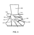
- an aspect of the present invention solves the problem of gaining access to preform nondestructive in-situ testing of machine components, such as an airfoil/blade 250 or vane by scanning, rastering or sweeping an ultrasonic beam 312 (phased array ultrasound) to inspect airfoil 250 for defects using different orientations with one scan.
- the horizontal line 314 of beam 312 represents a sound path normal to or directly below a transducer probe 316.
- the vertical line 318 of beam 312 represents 90 degrees of beam scanning.
- the cracked line/defect 320 shown in airfoil 250 indicates a defect in the airfoil.
- FIG. 3 the horizontal line 314 of beam 312 represents a sound path normal to or directly below a transducer probe 316.
- the vertical line 318 of beam 312 represents 90 degrees of beam scanning.
- the cracked line/defect 320 shown in airfoil 250 indicates a defect in the airfoil.
- defect 320 can only be seen if the operator using probe 316 is using about a 50° beam angle relative to the normal beam 314. As the surface 322 where transducer 316 is in contact with airfoil 250 changes its orientation, the angle at which beam 312 enters airfoil 250 changes, so that the angle of beam 312 to scan the area of interest 324 in airfoil 250 will change accordingly.
- the phased array transducer probe 316 used with the apparatus and method of the present invention may be a linear array probe which is comprised of a series of transducers. Each of these transducers is triggered at predetermined time intervals and receives an ultrasound signal back at predetermined time intervals. This predetermined triggering and receiving is the phasing which allows the steering of beam 312.
- the ultrasound signals acquired by each transducer are then processed by a computer programmed to give a composite view of the area of interest 324 that is being examined.
- the range of angles which are needed to keep the area of interest 324 in view must first be determined.
- a sector scan or sweep is then set up which is comprised of the angles required for inspection of the area of interest.
- the entire area of interest 324 can be monitored without interruption of the test.
- parts in a machine with limited access such as airfoils, can be readily inspected without disassembling the machine containing the airfoil. This is because the inspection method of the present invention does not require complete disassembly of the machine to access all areas of interest by physical means.
- a phased array beam an operator can see all beam angles of interest in one scan. This allows for a more comprehensive view of the inspection area 324 and reduces the test variation.
- FIG. 4 illustrates a perspective view of an apparatus 400 that can be used to inspect turbomachines (e.g., compressors) in-situ, according to an aspect of the present invention.
- the apparatus 400 includes a handle 410 that is connected to a tube or rod 420.
- the rod (or tube) 420 is at least partially bendable or malleable, so that it may be bent into a suitable or desired shape to fit around (and avoid contact with) the blades and vanes in the compressor stages.
- the tube 420 is connected to an end effector 430 that contains a transducer probe.
- the handle 410 may include a rounded bottom 412 into which one end of the tube 420 may be inserted and secured. For example, a set screw (not shown) may pass through the rounded bottom and/or the tube 420 to secure the handle 410 to the tube.
- the handle 410 is manipulated by an operator to maneuver the apparatus through the various stages of vanes and blades of the compressor.
- FIG. 5 illustrates a perspective view of the end effector 430, according to an aspect of the present invention.
- the end effector includes a frame 510 that has a substantially triangular shape, and this frame 510 defines a stable platform with a curved surface of the compressor blade or vane.
- the frame 510 also includes three cylindrical shells 512 that hold magnets 514, and low friction contact points 516 made of a low friction material or including a low friction coating.
- the magnets 514 (or magnetic elements) provide an attractive force between the end effector 430 and the compressor blade, and this attractive force helps an operator maintain contact between the end effector and blade during an inspection procedure.
- the low friction coating or low friction material may be formed of polytetrafluoroethylene (PTFE) or any other suitable low friction material that reduces friction and facilitates movement of the end effector 430 along the curved surface of the compressor blade or vane.
- PTFE polytetrafluoroethylene
- the end effector 430 is connected to the rod 420 via a rod coupler 520.
- One end of the rod 420 may be held in the rod coupler by a compression fitting, a set screw or any other suitable retaining means.
- the end effector 430 also includes a spring loaded suspension attached to the frame 510.
- the spring loaded suspension includes the yoke 540, springs 542 and screws 544.
- the spring loaded suspension provides pitch and roll motion to the probe 530 and wedge member 535 so that it can keep constant and uniform contact with the compressor blade during the scanning of areas or interest for inspection and provides a force to press a yoke 540 toward the blade.
- the wedge member 535 may be mounted to the yoke 540 via two screws 541 that act as a pivot joint for the wedge member 535.
- This pivot joint is positioned such that the load from the spring loaded suspension system is directed in line with a region of the wedge member 535 that must be in intimate contact with the blade.
- This suspension system forces the wedge to be firmly and squarely pressed against the blade even as the frame is slid along the width of the blade and the curvature changes below the wedge member.
- the wedge member 535 may be formed of a material that permits transmission of ultrasonic signals, such as poly(methyl methacrylate) (PMMA) or cross-linked polystyrene, and has a rounded bottom 536 to fit the curvature of the blade against the platform and provide a suitable offset to have non-destructive test (NDT) signals (e.g., ultrasonic signals) enter the component or blade at a suitable angle and distance to the areas to be inspected.
- NDT non-destructive test
- the wedge member 535 may also be connected to an ultrasonic coupling medium conduit 550 that may be routed back along rod 420 to a source of ultrasonic coupling medium (not shown).
- the wedge member 535 may have an ultrasonic coupling medium input (not shown) connected to the ultrasonic coupling medium supply conduit 550 and one or more ultrasonic coupling medium outputs 538.
- the ultrasonic coupling medium is used to couple ultrasonically the airfoil 250 and the wedge 535.
- Any suitable ultrasonic coupling medium or gel may be used, and as only one non-limiting example, the ultrasonic coupling medium may be a gel comprised of one or more of propylene glycol, glycerin and water.
- FIG. 6 illustrates a top view of the end effector 430, according to an aspect of the present invention.
- the end effector 430 is connected to the rod coupler via a pivot joint 610.
- the pivot joint 610 allows the end effector to pivot up or down in the plane of the drawing (as illustrated by the curved arrow).
- the spring loaded suspension allows the yoke to move as well. For example, the top of the yoke 540 may move left while the bottom of the yoke 540 may move to the right, in the plane of the drawing.
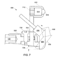
- FIG. 7 illustrates a cross-sectional view of the end effector 430, according to an aspect of the present invention.
- the substantially cylindrical shells 512 may have magnets 514 secured by set screws 710.
- the set screws may 710 also be used to hold the low friction contact points 516 in place as well.
- the set screws may be externally threaded, and these external threads can mate with internal threads on the interior walls of cylindrical shells 512.
- the offset distance 720 causes the spring loaded suspension to provide a downward force against the base of the blade and forces the wedge to rotate downward.
- the pivot joint 610 may be comprised of a shoulder screw 730 that passes through a portion of frame 510 and a tang of rod coupler 520.
- FIG. 8 illustrates a partial perspective view of the compressor airfoils and vanes, with the casing omitted for clarity, and the apparatus 400 inserted to perform an inspection on an R1 rotor blade, according to an aspect of the present invention.
- the end effector 430 is attached to the bendable rod 420 via the pivot joint 610 and this pivot allows the single degree of freedom necessary to keep the three points (defined by the end of the cylindrical shells/low friction points) in contact with the blade as an operator slides the apparatus 400 back and forth along the base of the blade as the inspection is taking place.
- the bendable rod 420 allows the operator to maneuver the mechanism into the compressor and place it on the blade with the aid of the magnetic attraction (via magnets 514).
- the pre-formed shape of rod 420 may be specifically designed so the operator can provide control motions to the end effector 430 to cover all the areas of interest without contacting the various blades/vanes between the operator and the blade being inspected.
- the bendable rod 420 is maneuvered with the aid of handle 410 with rounded bottom 412 to allow free rotation of the apparatus 400 and end effector 430 as the geometry of the area to be inspected changes along the platform of the blade.
Landscapes
- General Health & Medical Sciences (AREA)
- General Physics & Mathematics (AREA)
- Life Sciences & Earth Sciences (AREA)
- Chemical & Material Sciences (AREA)
- Analytical Chemistry (AREA)
- Biochemistry (AREA)
- Health & Medical Sciences (AREA)
- Immunology (AREA)
- Physics & Mathematics (AREA)
- Pathology (AREA)
- Engineering & Computer Science (AREA)
- Mechanical Engineering (AREA)
- General Engineering & Computer Science (AREA)
- Structures Of Non-Positive Displacement Pumps (AREA)
- Investigating Or Analyzing Materials By The Use Of Ultrasonic Waves (AREA)
Abstract
Description
- The apparatus described herein relates generally to turbomachines. More specifically, the apparatus relates to inspecting turbomachine components in-situ.
- Gas turbine compressor blades can get damaged due to operation. In the event of such damage, timely detection and replacement of these blades are desirable to prevent airfoil liberation and subsequent compressor failure. The current practice for blade inspection requires compressor case removal, which is inevitably time consuming and expensive. The removal of the compressor case for inspection of compressor blades also creates undesirable outage time, thereby resulting in lost income for the machine owner/operator.
- In an aspect of the present invention, an apparatus is provided for inspecting a component of a turbomachine. The apparatus includes an end effector having a frame defining a stable platform with a curved surface of the component, a spring loaded suspension attached to the frame, and a probe connected to a wedge member, where the probe and wedge member are connected to the spring loaded suspension. The probe is configured to inspect the component in-situ by passing signals through the wedge.
- Embodiments of the present invention will now be described, by way of example only, with reference to the accompanying drawings in which:
-
FIG. 1 illustrates a partial, cut-away view of a turbomachine; -
FIG. 2 illustrates a partial perspective view of a compressor showing the airfoils and vanes; -
FIG. 3 illustrates a schematic diagram of nondestructively inspecting a component for defects using phased array ultrasound; -
FIG. 4 illustrates a perspective view of an apparatus that can be used to inspect turbomachines in-situ, according to an aspect of the present invention; -
FIG. 5 illustrates a perspective view of the end effector, according to an aspect of the present invention; -
FIG. 6 illustrates a top view of the end effector, according to an aspect of the present invention; -
FIG. 7 illustrates a cross-sectional view of the end effector, according to an aspect of the present invention; and -
FIG. 8 illustrates a partial perspective view of the compressor airfoils and vanes, with the casing omitted for clarity, and the apparatus inserted to perform an inspection on an R1 rotor blade, according to an aspect of the present invention. - The major challenge in the development of an in-situ blade inspection method and apparatus is to design a mechanism that can deliver the inspection tool to the target blade inside the compressor, due to the stringent spatial constraints imposed by the tight workspace within the compressor flow path. The delivery mechanism should be capable of reaching the desired portions of the target airfoil, blade or vane.
-
FIG. 1 illustrates a partial, cut-away view of aturbomachine 100, which may be a gas turbine compressor. However, it is to be understood that the present invention can be applied to any turbomachine, including but not limited to, gas turbines, steam turbines, compressors, or any machine that transfers energy between a rotor and a fluid. Incompressor 100, half of thecompressor bell mouth 110 is omitted to show the internal vanes and blades. Thebell mouth 110 includes anouter surface 112 and an inner surface 114, and incoming flow passes between these two surfaces. Typically, a plurality ofsupport members 116 are fastened or welded to theouter surface 112 and the inner surface 114 for support. The first stage of stator vanes is called the inlet guide vanes (IGVs) 120. -
FIG. 2 illustrates a partial perspective view of the compressor airfoils and vanes, with the casing omitted for clarity. The stator vanes are generally fixed, while the rotor airfoils/blades are connected torotatable rotor 204. Theinlet guide vanes 120 are generally fixed as well, but may pitch around a radial axis to vary the direction or amount of incoming flow. Theinlet guide vanes 120 are followed by a first row ofrotor airfoils 230. The airfoils can also be referred to as the R0 airfoils or R0 blades, as they are part of the R0 stage. Thestator vanes 240 are next, and can also be referred to as the S0 vanes, as they are part of the S0 stage. The next row of rotor airfoils/blades 250 can be referred to as the R1 airfoils or R1 blades, as they are part of the R1 stage. The R1 airfoils are followed by theS1 stator vanes 260, as they are part of theS 1 stage, and so on. - It would be desirable if a delivery mechanism could go through the
bell mouth 110 and reach the target blade or vane, as well as deliver an inspection tool to perform the desired inspection operation. As one example only, an R1 blade can experience various types of damage and this blade could be reached without requiring case removal, according to an aspect of the present invention. - Referring to
FIG. 3 , an aspect of the present invention solves the problem of gaining access to preform nondestructive in-situ testing of machine components, such as an airfoil/blade 250 or vane by scanning, rastering or sweeping an ultrasonic beam 312 (phased array ultrasound) to inspectairfoil 250 for defects using different orientations with one scan. As can be seen inFIG. 3 , thehorizontal line 314 ofbeam 312 represents a sound path normal to or directly below atransducer probe 316. Thevertical line 318 ofbeam 312 represents 90 degrees of beam scanning. The cracked line/defect 320 shown inairfoil 250 indicates a defect in the airfoil. As can be seen fromFIG. 3 ,defect 320 can only be seen if theoperator using probe 316 is using about a 50° beam angle relative to thenormal beam 314. As thesurface 322 wheretransducer 316 is in contact withairfoil 250 changes its orientation, the angle at whichbeam 312 entersairfoil 250 changes, so that the angle ofbeam 312 to scan the area ofinterest 324 inairfoil 250 will change accordingly. - The phased
array transducer probe 316 used with the apparatus and method of the present invention may be a linear array probe which is comprised of a series of transducers. Each of these transducers is triggered at predetermined time intervals and receives an ultrasound signal back at predetermined time intervals. This predetermined triggering and receiving is the phasing which allows the steering ofbeam 312. The ultrasound signals acquired by each transducer are then processed by a computer programmed to give a composite view of the area ofinterest 324 that is being examined. - To inspect a
blade 250 from itsblade surface 322, the range of angles which are needed to keep the area ofinterest 324 in view must first be determined. A sector scan or sweep is then set up which is comprised of the angles required for inspection of the area of interest. During inspection, the entire area ofinterest 324 can be monitored without interruption of the test. Also, by using an ultrasonic phased array sector scan, parts in a machine with limited access, such as airfoils, can be readily inspected without disassembling the machine containing the airfoil. This is because the inspection method of the present invention does not require complete disassembly of the machine to access all areas of interest by physical means. By using a phased array beam, an operator can see all beam angles of interest in one scan. This allows for a more comprehensive view of theinspection area 324 and reduces the test variation. -
FIG. 4 illustrates a perspective view of anapparatus 400 that can be used to inspect turbomachines (e.g., compressors) in-situ, according to an aspect of the present invention. Theapparatus 400 includes ahandle 410 that is connected to a tube orrod 420. Preferably, the rod (or tube) 420 is at least partially bendable or malleable, so that it may be bent into a suitable or desired shape to fit around (and avoid contact with) the blades and vanes in the compressor stages. Thetube 420 is connected to anend effector 430 that contains a transducer probe. Thehandle 410 may include arounded bottom 412 into which one end of thetube 420 may be inserted and secured. For example, a set screw (not shown) may pass through the rounded bottom and/or thetube 420 to secure thehandle 410 to the tube. Thehandle 410 is manipulated by an operator to maneuver the apparatus through the various stages of vanes and blades of the compressor. -
FIG. 5 illustrates a perspective view of theend effector 430, according to an aspect of the present invention. The end effector includes aframe 510 that has a substantially triangular shape, and thisframe 510 defines a stable platform with a curved surface of the compressor blade or vane. Theframe 510 also includes threecylindrical shells 512 that holdmagnets 514, and low friction contact points 516 made of a low friction material or including a low friction coating. The magnets 514 (or magnetic elements) provide an attractive force between theend effector 430 and the compressor blade, and this attractive force helps an operator maintain contact between the end effector and blade during an inspection procedure. The low friction coating or low friction material may be formed of polytetrafluoroethylene (PTFE) or any other suitable low friction material that reduces friction and facilitates movement of theend effector 430 along the curved surface of the compressor blade or vane. - The
end effector 430 is connected to therod 420 via arod coupler 520. One end of therod 420 may be held in the rod coupler by a compression fitting, a set screw or any other suitable retaining means. Theend effector 430 also includes a spring loaded suspension attached to theframe 510. The spring loaded suspension includes theyoke 540, springs 542 and screws 544. The spring loaded suspension provides pitch and roll motion to theprobe 530 andwedge member 535 so that it can keep constant and uniform contact with the compressor blade during the scanning of areas or interest for inspection and provides a force to press ayoke 540 toward the blade. Thewedge member 535 may be mounted to theyoke 540 via twoscrews 541 that act as a pivot joint for thewedge member 535. This pivot joint is positioned such that the load from the spring loaded suspension system is directed in line with a region of thewedge member 535 that must be in intimate contact with the blade. This suspension system forces the wedge to be firmly and squarely pressed against the blade even as the frame is slid along the width of the blade and the curvature changes below the wedge member. - The
wedge member 535, may be formed of a material that permits transmission of ultrasonic signals, such as poly(methyl methacrylate) (PMMA) or cross-linked polystyrene, and has a roundedbottom 536 to fit the curvature of the blade against the platform and provide a suitable offset to have non-destructive test (NDT) signals (e.g., ultrasonic signals) enter the component or blade at a suitable angle and distance to the areas to be inspected. Thewedge member 535 may also be connected to an ultrasoniccoupling medium conduit 550 that may be routed back alongrod 420 to a source of ultrasonic coupling medium (not shown). Thewedge member 535 may have an ultrasonic coupling medium input (not shown) connected to the ultrasonic couplingmedium supply conduit 550 and one or more ultrasonic coupling medium outputs 538. The ultrasonic coupling medium is used to couple ultrasonically theairfoil 250 and thewedge 535. Any suitable ultrasonic coupling medium or gel may be used, and as only one non-limiting example, the ultrasonic coupling medium may be a gel comprised of one or more of propylene glycol, glycerin and water. -
FIG. 6 illustrates a top view of theend effector 430, according to an aspect of the present invention. Theend effector 430 is connected to the rod coupler via apivot joint 610. The pivot joint 610 allows the end effector to pivot up or down in the plane of the drawing (as illustrated by the curved arrow). The spring loaded suspension allows the yoke to move as well. For example, the top of theyoke 540 may move left while the bottom of theyoke 540 may move to the right, in the plane of the drawing. -
FIG. 7 illustrates a cross-sectional view of theend effector 430, according to an aspect of the present invention. The substantiallycylindrical shells 512 may havemagnets 514 secured byset screws 710. The set screws may 710 also be used to hold the low friction contact points 516 in place as well. The set screws may be externally threaded, and these external threads can mate with internal threads on the interior walls ofcylindrical shells 512. The offsetdistance 720 causes the spring loaded suspension to provide a downward force against the base of the blade and forces the wedge to rotate downward. The pivot joint 610 may be comprised of ashoulder screw 730 that passes through a portion offrame 510 and a tang ofrod coupler 520. -
FIG. 8 illustrates a partial perspective view of the compressor airfoils and vanes, with the casing omitted for clarity, and theapparatus 400 inserted to perform an inspection on an R1 rotor blade, according to an aspect of the present invention. Theend effector 430 is attached to thebendable rod 420 via the pivot joint 610 and this pivot allows the single degree of freedom necessary to keep the three points (defined by the end of the cylindrical shells/low friction points) in contact with the blade as an operator slides theapparatus 400 back and forth along the base of the blade as the inspection is taking place. Thebendable rod 420 allows the operator to maneuver the mechanism into the compressor and place it on the blade with the aid of the magnetic attraction (via magnets 514). The pre-formed shape ofrod 420 may be specifically designed so the operator can provide control motions to theend effector 430 to cover all the areas of interest without contacting the various blades/vanes between the operator and the blade being inspected. Thebendable rod 420 is maneuvered with the aid ofhandle 410 withrounded bottom 412 to allow free rotation of theapparatus 400 andend effector 430 as the geometry of the area to be inspected changes along the platform of the blade. - This written description uses examples to disclose the invention, including the best mode, and also to enable any person skilled in the art to practice the invention, including making and using any devices or systems and performing any incorporated methods. The patentable scope of the invention is defined by the claims, and may include other examples that occur to those skilled in the art. Such other examples are intended to be within the scope of the claims if they have structural elements that do not differ from the literal language of the claims, or if they include equivalent structural elements with insubstantial differences from the literal languages of the claims.
Claims (12)
- An apparatus (400) adapted for inspecting a component (250) of a turbomachine, the apparatus comprising:an end effector (430) comprising:a frame (510) defining a stable platform with a curved surface of the component;a spring loaded suspension (540) attached to the frame;a probe (530) connected to a wedge member (535), the probe and wedge member connected to the spring loaded suspension;wherein the probe is configured to inspect the component in-situ by passing signals through the wedge.
- The apparatus of claim 1, wherein the probe (530) is an ultrasonic transducer capable of sending and receiving ultrasonic signals.
- The apparatus of claim 1 or 2, the frame (510) further comprising a substantially triangular frame having three substantially cylindrical shells (512), the substantially cylindrical shells each having a substantially hemispherical contact point (516) for contacting the curved surface of the component.
- The apparatus of claim 3, each of the three substantially cylindrical shells further comprising:a magnetic element (514); anda low friction material located either in or on the substantially hemispherical contact point (516);wherein the magnetic element provides an attractive force to help an operator maintain contact between the end effector and the component, and the low friction material facilitates movement of the end effector along the curved surface of the component.
- The apparatus of claim 4, wherein the low friction material is polytetrafluoroethylene (PTFE).
- The apparatus of any preceding claim, further comprising:a bendable rod (420) connected to the end effector;a handle (410) attached to the bendable rod; andwherein the frame is connected to the bendable rod via a pivoting connection and a rod coupler.
- The apparatus of any preceding claim, the end effector further comprising:a yoke (540) connected to the spring loaded suspension and the probe and wedge member, the yoke connected to the wedge member by a pivoting connection.
- The apparatus of any preceding claim, the wedge member further comprising:a rounded bottom (536) configured to fit the curvature of the component and to provide an offset so the signals enter the component at a predetermined angle and distance to an area of interest.
- The apparatus of any of claims 2 to 8, the end effector further comprising:an ultrasonic coupling medium supply conduit (550) connected to the wedge member;wherein the ultrasonic coupling medium supply conduit supplies an ultrasonic coupling medium, and the wedge member comprises an ultrasonic coupling medium input connected to the ultrasonic coupling medium supply conduit and an ultrasonic coupling medium output to facilitate ultrasonic coupling between the wedge member and the component.
- The apparatus of claim 9, wherein the ultrasonic coupling medium is a gel comprising at least one of, propylene glycol, glycerin and water.
- The apparatus of any preceding claim, wherein the turbomachine is at least one of a compressor and a gas turbine.
- The apparatus of claim 11, wherein the turbomachine is the compressor and the component is at least one of a blade and a vane.
Applications Claiming Priority (1)
| Application Number | Priority Date | Filing Date | Title |
|---|---|---|---|
| US13/181,803 US8365584B1 (en) | 2011-07-13 | 2011-07-13 | Apparatus for inspecting turbomachine components in-situ |
Publications (2)
| Publication Number | Publication Date |
|---|---|
| EP2546643A2 true EP2546643A2 (en) | 2013-01-16 |
| EP2546643A3 EP2546643A3 (en) | 2013-03-13 |
Family
ID=46969968
Family Applications (1)
| Application Number | Title | Priority Date | Filing Date |
|---|---|---|---|
| EP12175806A Withdrawn EP2546643A3 (en) | 2011-07-13 | 2012-07-10 | Apparatus for inspecting turbomachine components in-situ |
Country Status (3)
| Country | Link |
|---|---|
| US (1) | US8365584B1 (en) |
| EP (1) | EP2546643A3 (en) |
| CN (1) | CN102879467B (en) |
Cited By (1)
| Publication number | Priority date | Publication date | Assignee | Title |
|---|---|---|---|---|
| PL446270A1 (en) * | 2023-09-29 | 2025-03-31 | Odlewnia Kutno Spółka Z Ograniczoną Odpowiedzialnością | Robotic station for quality control of metal castings |
Families Citing this family (21)
| Publication number | Priority date | Publication date | Assignee | Title |
|---|---|---|---|---|
| US9037419B2 (en) | 2011-05-10 | 2015-05-19 | Edison Welding Institute, Inc. | Portable matrix phased array spot weld inspection system |
| US9063059B2 (en) | 2011-05-10 | 2015-06-23 | Edison Welding Institute, Inc. | Three-dimensional matrix phased array spot weld inspection system |
| US8713775B2 (en) * | 2011-06-16 | 2014-05-06 | General Electric Company | Apparatus and method for servicing dynamoelectric machine components in-situ |
| JP2013185456A (en) * | 2012-03-06 | 2013-09-19 | Toshiba Corp | Method of measuring steam turbine, measuring device, and method of manufacturing steam turbine |
| US9027404B2 (en) * | 2012-05-17 | 2015-05-12 | Honeywell International Inc. | Ultrasonic non-destructive evaluation methods for friction-welded blisks |
| US20160023772A1 (en) * | 2013-07-26 | 2016-01-28 | Fbs, Inc. | Ultrasonic vibration system and method for removing/avoiding unwanted build-up on structures |
| US9348001B2 (en) * | 2013-10-21 | 2016-05-24 | General Electric Company | Method and system for detecting surface features on turbine components |
| JP6300225B2 (en) * | 2013-12-03 | 2018-03-28 | 東芝エネルギーシステムズ株式会社 | Turbine blade inspection device and inspection method thereof |
| FR3020463B1 (en) * | 2014-04-25 | 2016-05-27 | Snecma | METHOD AND DEVICE FOR ULTRASONIC INSPECTION OF WELDINGS, ESPECIALLY AUBES WELDING ON THE DISK OF A MONOBLOC AUBING DISK |
| CN105717195B (en) * | 2014-12-03 | 2018-09-07 | 国家电网公司 | Partition board main weld detecting system and detection method |
| CN105004790A (en) * | 2015-07-13 | 2015-10-28 | 中国人民解放军装甲兵工程学院 | Compressor impeller defect phased array ultrasonic detection method |
| WO2017165010A2 (en) * | 2016-02-09 | 2017-09-28 | Huggett Daniel J | On-line phased array ultrasonic testing system for friction stir welding applications |
| US10920590B2 (en) * | 2016-06-30 | 2021-02-16 | General Electric Company | Turbine assembly maintenance methods |
| NL2017525B1 (en) * | 2016-09-23 | 2018-04-04 | Roentgen Technische Dienst B V | Probe holder system |
| DE102016219171A1 (en) * | 2016-10-04 | 2018-04-05 | Siemens Aktiengesellschaft | Method for non-destructive material testing |
| US10808534B2 (en) * | 2017-02-08 | 2020-10-20 | General Electric Company | Reconfigurable maintenance apparatus |
| US11103964B2 (en) * | 2018-12-06 | 2021-08-31 | General Electric Company | Service apparatus for use with rotary machines |
| CN109839436B (en) * | 2019-01-23 | 2020-11-20 | 浙江大学 | Synchronous fusion method of ultrasonic data and position data in helical scanning mode |
| EP4097439A4 (en) * | 2020-01-30 | 2024-03-13 | Quest Integrity Group, LLC | IMPROVEMENT OF GEL MILKING |
| US11686710B2 (en) | 2020-03-31 | 2023-06-27 | Evident Canada, Inc. | Longitudinal and circumferential ultrasound scanner |
| USD1103806S1 (en) | 2020-10-22 | 2025-12-02 | Evident Canada, Inc. | Scanner frame |
Family Cites Families (24)
| Publication number | Priority date | Publication date | Assignee | Title |
|---|---|---|---|---|
| DE4241767C1 (en) | 1992-12-11 | 1993-12-09 | Wolf Gmbh Richard | Machining and viewing unit for entry in inspection hole e.g. for turbine blade repair - has tool for machining and optic e.g. technoscope, with shaft for simultaneous viewing of machining place with head jointed at distal end and swivelable relative to unit longitudinal axis |
| US5670879A (en) * | 1993-12-13 | 1997-09-23 | Westinghouse Electric Corporation | Nondestructive inspection device and method for monitoring defects inside a turbine engine |
| US5644394A (en) | 1994-10-19 | 1997-07-01 | United Technologies Corporation | System for repairing damaged gas turbine engine airfoils |
| US5535628A (en) * | 1994-11-14 | 1996-07-16 | Rohrback Cosasco Systems, Inc. | Ultrasonic scanner head and method |
| US5576492A (en) * | 1995-01-26 | 1996-11-19 | United Technologies Corporation | Mechanical contour follower |
| US5623107A (en) * | 1995-05-22 | 1997-04-22 | General Electric Co. | Wheel dovetail scanner |
| US5781007A (en) * | 1995-10-24 | 1998-07-14 | General Electric Company | Portable three axis scanner to inspect a gas turbine engine spool by eddy current or ultrasonic inspection |
| US5913243A (en) * | 1997-09-30 | 1999-06-15 | General Electric Co. | Ultrasonic transducer for nondestructive testing of generator field coils of dynamoelectric machines |
| US6082198A (en) * | 1998-12-30 | 2000-07-04 | Electric Power Research Institute Inc. | Method of ultrasonically inspecting turbine blade attachments |
| US6736011B2 (en) * | 2000-12-07 | 2004-05-18 | Electric Power Research Institute, Inc. | Inspection of shrunk-on steam turbine disks using advanced ultrasonic techniques |
| US6904818B2 (en) * | 2002-04-05 | 2005-06-14 | Vetco Gray Inc. | Internal riser inspection device |
| US7032279B2 (en) | 2002-10-18 | 2006-04-25 | General Electric Company | Apparatus and methods for repairing compressor airfoils in situ |
| US7174788B2 (en) | 2003-12-15 | 2007-02-13 | General Electric Company | Methods and apparatus for rotary machinery inspection |
| US7010982B2 (en) | 2004-04-30 | 2006-03-14 | General Electric Company | Method of ultrasonically inspecting airfoils |
| EP1610122A1 (en) * | 2004-06-01 | 2005-12-28 | Siemens Aktiengesellschaft | Method and apparatus for determination of defects in a turbine blade by means of an ultrasonic phased array transducer |
| EP1855835A4 (en) * | 2005-02-28 | 2014-04-30 | Electric Power Res Inst | INSPECTION AND REPAIR PROCESS |
| US7313961B2 (en) * | 2005-04-26 | 2008-01-01 | General Electric Company | Method and apparatus for inspecting a component |
| US7606445B2 (en) | 2005-11-30 | 2009-10-20 | General Electric Company | Methods and systems for ultrasound inspection |
| US7766726B2 (en) | 2006-11-16 | 2010-08-03 | General Electric Company | In-situ compressor blade tip cropping assembly and method |
| US7669477B2 (en) * | 2006-12-22 | 2010-03-02 | The Boeing Company | Ultrasonic probe for hollow fuse pin inspection |
| US7654143B2 (en) | 2007-04-03 | 2010-02-02 | General Electric Company | Method and apparatus for in-situ inspection of rotary machine components |
| US8028581B2 (en) * | 2008-08-08 | 2011-10-04 | Toyota Motor Engineering & Manufacturing North America, Inc. | Methods and systems for ultrasonic inspection of rotating shafts |
| US8109160B2 (en) * | 2009-02-06 | 2012-02-07 | The Boeing Company | Inspection apparatus |
| US8347746B2 (en) * | 2010-01-19 | 2013-01-08 | The Boeing Company | Crawling automated scanner for non-destructive inspection of aerospace structural elements |
-
2011
- 2011-07-13 US US13/181,803 patent/US8365584B1/en active Active
-
2012
- 2012-07-10 EP EP12175806A patent/EP2546643A3/en not_active Withdrawn
- 2012-07-13 CN CN201210242583.XA patent/CN102879467B/en not_active Expired - Fee Related
Non-Patent Citations (1)
| Title |
|---|
| None |
Cited By (3)
| Publication number | Priority date | Publication date | Assignee | Title |
|---|---|---|---|---|
| PL446270A1 (en) * | 2023-09-29 | 2025-03-31 | Odlewnia Kutno Spółka Z Ograniczoną Odpowiedzialnością | Robotic station for quality control of metal castings |
| WO2025071420A1 (en) * | 2023-09-29 | 2025-04-03 | Odlewnia Kutno Sp. Z O.O. | Robotised workstation for quality control of metal castings |
| PL248161B1 (en) * | 2023-09-29 | 2025-10-27 | Odlewnia Kutno Spolka Z Ograniczona Odpowiedzialnoscia | Robotic station for quality control of metal castings |
Also Published As
| Publication number | Publication date |
|---|---|
| US20130014571A1 (en) | 2013-01-17 |
| EP2546643A3 (en) | 2013-03-13 |
| CN102879467A (en) | 2013-01-16 |
| CN102879467B (en) | 2016-07-06 |
| US8365584B1 (en) | 2013-02-05 |
Similar Documents
| Publication | Publication Date | Title |
|---|---|---|
| US8365584B1 (en) | Apparatus for inspecting turbomachine components in-situ | |
| US7302851B2 (en) | Methods and apparatus for rotary machinery inspection | |
| US7654143B2 (en) | Method and apparatus for in-situ inspection of rotary machine components | |
| US7428842B2 (en) | Phased array ultrasonic testing system and methods of examination and modeling employing the same | |
| EP2881734B1 (en) | Ultrasonic turbine blade testing device and testing method thereof | |
| US8042399B2 (en) | Method and a device for inspecting a pipe connection weld by an ultrasound probe | |
| US8181528B2 (en) | Method and system for ultrasonic inspection of gearbox ring gear | |
| US8813567B2 (en) | Low profile ultrasound inspection scanner | |
| JP2019060888A (en) | Apparatus for non-destructive inspection of stringer | |
| KR100304079B1 (en) | Lamb wave ultrasonic probe for crack detection and measurement in thin-walled tubing and method for inspecting defects in the tubing using the same | |
| US20150233869A1 (en) | Ultrasonic phased array transducer for the nde inspection of the jet pump riser welds and welded attachments | |
| US8438929B2 (en) | Phased array ultrasonic inspection system for turbine and generator rotor bore | |
| EP1322952B1 (en) | Steam turbine inlet sleeve inspection apparatus and method | |
| JPH04301797A (en) | Apparatus for ultrasonic non-destructive inspection for slender part having substantially constant cross section | |
| JP5622597B2 (en) | Ultrasonic flaw detection apparatus and ultrasonic flaw detection method | |
| US7313961B2 (en) | Method and apparatus for inspecting a component | |
| CN108291894B (en) | Method, system and fixture for inspecting gasket welds | |
| US6222897B1 (en) | Wrist raster scan methods | |
| US9285346B2 (en) | Pipe processing device and pipe processing method | |
| JP2001065778A (en) | Piping inspection probe | |
| KR101745699B1 (en) | A non-destructive inspection apparatus for turbine blades | |
| US8395378B2 (en) | Nondestructive robotic inspection method and system therefor | |
| CN109580785A (en) | Scanning tooling and method for turbine blade root defect | |
| KR100567662B1 (en) | Turbine Blade Root NDT in Power Plant | |
| JP2007017164A (en) | Ultrasonic flaw detection method and flaw detection system |
Legal Events
| Date | Code | Title | Description |
|---|---|---|---|
| PUAI | Public reference made under article 153(3) epc to a published international application that has entered the european phase |
Free format text: ORIGINAL CODE: 0009012 |
|
| AK | Designated contracting states |
Kind code of ref document: A2 Designated state(s): AL AT BE BG CH CY CZ DE DK EE ES FI FR GB GR HR HU IE IS IT LI LT LU LV MC MK MT NL NO PL PT RO RS SE SI SK SM TR |
|
| AX | Request for extension of the european patent |
Extension state: BA ME |
|
| PUAL | Search report despatched |
Free format text: ORIGINAL CODE: 0009013 |
|
| AK | Designated contracting states |
Kind code of ref document: A3 Designated state(s): AL AT BE BG CH CY CZ DE DK EE ES FI FR GB GR HR HU IE IS IT LI LT LU LV MC MK MT NL NO PL PT RO RS SE SI SK SM TR |
|
| AX | Request for extension of the european patent |
Extension state: BA ME |
|
| RIC1 | Information provided on ipc code assigned before grant |
Ipc: G01N 29/28 20060101ALI20130207BHEP Ipc: G01N 29/22 20060101AFI20130207BHEP Ipc: G01N 29/265 20060101ALI20130207BHEP |
|
| 17P | Request for examination filed |
Effective date: 20130913 |
|
| RBV | Designated contracting states (corrected) |
Designated state(s): AL AT BE BG CH CY CZ DE DK EE ES FI FR GB GR HR HU IE IS IT LI LT LU LV MC MK MT NL NO PL PT RO RS SE SI SK SM TR |
|
| 17Q | First examination report despatched |
Effective date: 20170313 |
|
| STAA | Information on the status of an ep patent application or granted ep patent |
Free format text: STATUS: THE APPLICATION IS DEEMED TO BE WITHDRAWN |
|
| 18D | Application deemed to be withdrawn |
Effective date: 20200201 |