EP2546568A2 - Vehicle illumination lamp - Google Patents
Vehicle illumination lamp Download PDFInfo
- Publication number
- EP2546568A2 EP2546568A2 EP12174800A EP12174800A EP2546568A2 EP 2546568 A2 EP2546568 A2 EP 2546568A2 EP 12174800 A EP12174800 A EP 12174800A EP 12174800 A EP12174800 A EP 12174800A EP 2546568 A2 EP2546568 A2 EP 2546568A2
- Authority
- EP
- European Patent Office
- Prior art keywords
- light
- reflector
- intensity distribution
- luminous intensity
- distribution pattern
- Prior art date
- Legal status (The legal status is an assumption and is not a legal conclusion. Google has not performed a legal analysis and makes no representation as to the accuracy of the status listed.)
- Granted
Links
- 238000005286 illumination Methods 0.000 title claims description 48
- 230000003287 optical effect Effects 0.000 claims description 21
- 239000000470 constituent Substances 0.000 description 5
- 238000010586 diagram Methods 0.000 description 4
- 230000015572 biosynthetic process Effects 0.000 description 3
- 239000002131 composite material Substances 0.000 description 2
- 229910052736 halogen Inorganic materials 0.000 description 1
- 150000002367 halogens Chemical class 0.000 description 1
Images


Classifications
-
- F—MECHANICAL ENGINEERING; LIGHTING; HEATING; WEAPONS; BLASTING
- F21—LIGHTING
- F21S—NON-PORTABLE LIGHTING DEVICES; SYSTEMS THEREOF; VEHICLE LIGHTING DEVICES SPECIALLY ADAPTED FOR VEHICLE EXTERIORS
- F21S41/00—Illuminating devices specially adapted for vehicle exteriors, e.g. headlamps
- F21S41/60—Illuminating devices specially adapted for vehicle exteriors, e.g. headlamps characterised by a variable light distribution
- F21S41/68—Illuminating devices specially adapted for vehicle exteriors, e.g. headlamps characterised by a variable light distribution by acting on screens
- F21S41/683—Illuminating devices specially adapted for vehicle exteriors, e.g. headlamps characterised by a variable light distribution by acting on screens by moving screens
- F21S41/686—Blades, i.e. screens moving in a vertical plane
-
- F—MECHANICAL ENGINEERING; LIGHTING; HEATING; WEAPONS; BLASTING
- F21—LIGHTING
- F21S—NON-PORTABLE LIGHTING DEVICES; SYSTEMS THEREOF; VEHICLE LIGHTING DEVICES SPECIALLY ADAPTED FOR VEHICLE EXTERIORS
- F21S41/00—Illuminating devices specially adapted for vehicle exteriors, e.g. headlamps
- F21S41/10—Illuminating devices specially adapted for vehicle exteriors, e.g. headlamps characterised by the light source
- F21S41/14—Illuminating devices specially adapted for vehicle exteriors, e.g. headlamps characterised by the light source characterised by the type of light source
- F21S41/141—Light emitting diodes [LED]
- F21S41/147—Light emitting diodes [LED] the main emission direction of the LED being angled to the optical axis of the illuminating device
- F21S41/148—Light emitting diodes [LED] the main emission direction of the LED being angled to the optical axis of the illuminating device the main emission direction of the LED being perpendicular to the optical axis
-
- F—MECHANICAL ENGINEERING; LIGHTING; HEATING; WEAPONS; BLASTING
- F21—LIGHTING
- F21S—NON-PORTABLE LIGHTING DEVICES; SYSTEMS THEREOF; VEHICLE LIGHTING DEVICES SPECIALLY ADAPTED FOR VEHICLE EXTERIORS
- F21S41/00—Illuminating devices specially adapted for vehicle exteriors, e.g. headlamps
- F21S41/20—Illuminating devices specially adapted for vehicle exteriors, e.g. headlamps characterised by refractors, transparent cover plates, light guides or filters
- F21S41/25—Projection lenses
- F21S41/255—Lenses with a front view of circular or truncated circular outline
-
- F—MECHANICAL ENGINEERING; LIGHTING; HEATING; WEAPONS; BLASTING
- F21—LIGHTING
- F21S—NON-PORTABLE LIGHTING DEVICES; SYSTEMS THEREOF; VEHICLE LIGHTING DEVICES SPECIALLY ADAPTED FOR VEHICLE EXTERIORS
- F21S41/00—Illuminating devices specially adapted for vehicle exteriors, e.g. headlamps
- F21S41/30—Illuminating devices specially adapted for vehicle exteriors, e.g. headlamps characterised by reflectors
- F21S41/32—Optical layout thereof
- F21S41/321—Optical layout thereof the reflector being a surface of revolution or a planar surface, e.g. truncated
-
- F—MECHANICAL ENGINEERING; LIGHTING; HEATING; WEAPONS; BLASTING
- F21—LIGHTING
- F21S—NON-PORTABLE LIGHTING DEVICES; SYSTEMS THEREOF; VEHICLE LIGHTING DEVICES SPECIALLY ADAPTED FOR VEHICLE EXTERIORS
- F21S41/00—Illuminating devices specially adapted for vehicle exteriors, e.g. headlamps
- F21S41/30—Illuminating devices specially adapted for vehicle exteriors, e.g. headlamps characterised by reflectors
- F21S41/32—Optical layout thereof
- F21S41/323—Optical layout thereof the reflector having two perpendicular cross sections having regular geometrical curves of a distinct nature
-
- F—MECHANICAL ENGINEERING; LIGHTING; HEATING; WEAPONS; BLASTING
- F21—LIGHTING
- F21S—NON-PORTABLE LIGHTING DEVICES; SYSTEMS THEREOF; VEHICLE LIGHTING DEVICES SPECIALLY ADAPTED FOR VEHICLE EXTERIORS
- F21S41/00—Illuminating devices specially adapted for vehicle exteriors, e.g. headlamps
- F21S41/30—Illuminating devices specially adapted for vehicle exteriors, e.g. headlamps characterised by reflectors
- F21S41/32—Optical layout thereof
- F21S41/36—Combinations of two or more separate reflectors
-
- F—MECHANICAL ENGINEERING; LIGHTING; HEATING; WEAPONS; BLASTING
- F21—LIGHTING
- F21S—NON-PORTABLE LIGHTING DEVICES; SYSTEMS THEREOF; VEHICLE LIGHTING DEVICES SPECIALLY ADAPTED FOR VEHICLE EXTERIORS
- F21S41/00—Illuminating devices specially adapted for vehicle exteriors, e.g. headlamps
- F21S41/40—Illuminating devices specially adapted for vehicle exteriors, e.g. headlamps characterised by screens, non-reflecting members, light-shielding members or fixed shades
- F21S41/43—Illuminating devices specially adapted for vehicle exteriors, e.g. headlamps characterised by screens, non-reflecting members, light-shielding members or fixed shades characterised by the shape thereof
-
- F—MECHANICAL ENGINEERING; LIGHTING; HEATING; WEAPONS; BLASTING
- F21—LIGHTING
- F21S—NON-PORTABLE LIGHTING DEVICES; SYSTEMS THEREOF; VEHICLE LIGHTING DEVICES SPECIALLY ADAPTED FOR VEHICLE EXTERIORS
- F21S41/00—Illuminating devices specially adapted for vehicle exteriors, e.g. headlamps
- F21S41/60—Illuminating devices specially adapted for vehicle exteriors, e.g. headlamps characterised by a variable light distribution
- F21S41/65—Illuminating devices specially adapted for vehicle exteriors, e.g. headlamps characterised by a variable light distribution by acting on light sources
- F21S41/663—Illuminating devices specially adapted for vehicle exteriors, e.g. headlamps characterised by a variable light distribution by acting on light sources by switching light sources
-
- F—MECHANICAL ENGINEERING; LIGHTING; HEATING; WEAPONS; BLASTING
- F21—LIGHTING
- F21S—NON-PORTABLE LIGHTING DEVICES; SYSTEMS THEREOF; VEHICLE LIGHTING DEVICES SPECIALLY ADAPTED FOR VEHICLE EXTERIORS
- F21S41/00—Illuminating devices specially adapted for vehicle exteriors, e.g. headlamps
- F21S41/30—Illuminating devices specially adapted for vehicle exteriors, e.g. headlamps characterised by reflectors
- F21S41/32—Optical layout thereof
- F21S41/36—Combinations of two or more separate reflectors
- F21S41/365—Combinations of two or more separate reflectors successively reflecting the light
Definitions
- the present invention relates to a so-called projector type vehicle illumination lamp, and more particularly to a vehicle illumination lamp which is designed to form a variable luminous intensity distribution pattern.
- a projector type vehicle illumination lamp In general, in a projector type vehicle illumination lamp, light from a light source which is disposed further rearwards than a rear focal point of a projection lens is designed to be reflected towards the projection lens by a reflector.
- JP-A-2011-65960 describes a projector type vehicle illumination lamp which is designed to form a high-beam variable luminous intensity distribution pattern.
- a movable shade is disposed between the reflector and the projection lens.
- This movable shade is designed to shift between a light interruptive position where part of reflected light from the reflector is interrupted and a light uninterruptive position where the part of the reflected light becomes free from interruption or is left uninterrupted. Then, when this movable shade shifts to the light uninterruptive position, a high-beam luminous intensity distribution pattern is formed as a first variable luminous intensity distribution pattern, whereas when the movable shade shifts to the light interruptive position, a luminous intensity distribution pattern in which part of the high-beam luminous intensity distribution pattern is lost is formed as a second variable luminous intensity distribution pattern.
- the forward visibility of the driver of the subject vehicle can be enhanced without dazzling the driver of a preceding vehicle or an oncoming vehicle.
- a luminous intensity distribution pattern that is formed by the reflected light from the second reflector is formed into a constant pattern irrespective of the position of the movable shade. Therefore, when the movable shade shifts to the light interruptive position to form the second variable luminous intensity distribution pattern, part of the luminous intensity distribution pattern formed by the reflected light from the second reflector projects to a dark portion which is formed in the second variable luminous intensity distribution pattern when it is formed as a result of the part of the high-beam luminous intensity distribution pattern being lost. This causes a problem that the driver of a preceding vehicle or an oncoming vehicle is dazzled by the resulting luminous intensity distribution pattern.
- the invention has been made in view of these situations, and an object thereof is to provide a projector type vehicle illumination lamp designed to form a high-beam variable luminous intensity distribution pattern in which when a second variable luminous intensity distribution pattern is formed which lacks part of a high-beam luminous intensity distribution pattern as a first variable luminous intensity distribution pattern, the brightness of the first variable luminous intensity distribution pattern can be enhanced without dazzling the driver of a preceding vehicle or an oncoming vehicle.
- this object is attained by adopting a configuration in which a second light source and a second reflector are additionally provided and then devising an optimum relationship between them.
- a vehicle illumination lamp designed to form a high-beam variable luminous intensity distribution pattern
- the vehicle illumination lamp comprising a projection lens, a light source which is disposed further rearwards than a rear focal point of the projection lens, a reflector which reflects light from the light source towards the projection lens, and a movable shade which is disposed between the reflector and the projection lens so as to shift between a light interruptive position where part of reflected light from the reflector is interrupted so as to eliminate part of a high-beam luminous intensity distribution pattern and a light uninterruptive position where the interruption of the reflected light is released, wherein a second light source is disposed rearwards of the movable shade and a second reflector is disposed forwards of the movable shade, and wherein the second light source and the second reflector are disposed in such a positional relationship that when the movable shade shifts to the light uninterruptive position, light from the second light source is reflected by the second reflector so as
- the type of the "light source” is not limited to any specific type, and hence, for example, a light emitting portion of a discharge bulb, a filament of a halogen lamp or a light emitting chip of a light emitting element such as a light emitting diode can be adopted.
- the disposition of the "second light source” and the “second reflector” is not limited to any specific disposition as long as the second light source and the second reflector are disposed in such a positional relationship that when the movable shade shifts to the light uninterruptive position, light from the second light source is reflected by the second reflector so as to be shone to the front of the lamp without being allowed to be incident on the projection lens, while when the movable shade shifts to the light interruptive position, the light from the second light source is interrupted by the movable shade so as not to be incident on the second reflector.
- the vehicle illumination lamp according to the present invention configured as a projector type vehicle illumination lamp designed to form the high-beam variable luminous intensity distribution pattern
- the movable shade designed to selectively form the high-beam luminous intensity distribution pattern which is the first variable luminous intensity distribution pattern and the second variable luminous intensity distribution pattern in which part of the first variable luminous intensity distribution pattern is eliminated
- the second light source is disposed rearwards of the movable shade
- the second reflector is disposed forwards of the movable shade.
- the second light source and the second reflector are disposed in such a positional relationship that when the movable shade shifts to the light uninterruptive position, light from the second light source is reflected by the second reflector so as to be shone to the front of the lamp without being allowed to be incident on the projection lens, while when the movable shade shifts to the light interruptive position, the light from the second light source is interrupted by the movable shade so as not to be incident on the second reflector.
- the first variable luminous intensity distribution pattern is formed when the movable shade shifts to the light uninterruptive position, and as this occurs, the light from the second light source is reflected by the second reflector and is thereafter shone to the front of the lamp without being allowed to be incident on the projection lens. Therefore, the brightness of the first variable luminous intensity distribution pattern can be enhanced by a luminous intensity distribution pattern which is formed by the light shone to the front of the lamp.
- the second variable luminous intensity distribution pattern in which part of the first variable luminous intensity distribution pattern is eliminated is formed when the movable shade shifts to the light interruptive position.
- the light from the second light source is interrupted by the movable shade and is not allowed to be incident on the second reflector. Therefore, it becomes possible to prevent part of the luminous intensity distribution pattern which is formed by the reflected light from the second reflector from being formed so as to project to a dark portion in the second variable luminous intensity distribution pattern which is formed as a result of the part of the first movable luminous intensity distribution pattern being eliminated.
- the brightness of the first variable luminous intensity distribution pattern can be enhanced without dazzling the driver of a preceding or oncoming vehicle.
- the brightness of the high-beam variable luminous intensity distribution pattern can be enhanced further by a luminous intensity distribution pattern which is formed by the reflected light from the third reflector.
- the vehicle illumination lamp can be switched between a low beam and a high beam.
- the movable shade and the second movable shade can be disposed without any difficulty.
- the second light source is made up of a light emitting element which is disposed to be oriented upwards on or near to an optical axis of the projection lens
- the second light source is made up of a light emitting element which is disposed to be oriented downwards in a position lying further forwards than the light source and further upwards than the optical axis
- the second reflector is disposed further downwards than the optical axis
- the light source, the second light source and the second reflector can be disposed compact.
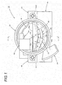
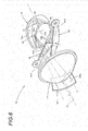
- Fig. 1 is a front view of a vehicle illumination lamp 10 according to an embodiment of the invention, which shows a state in which a movable shade 18 is in a light uninterruptive position and a second movable shade 28 is in a light interruptive position.
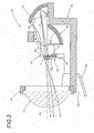
- Fig. 2 is a sectional view of the vehicle illumination lamp 10 which is taken along the line II-II in Fig. 1 .
- the vehicle illumination lamp 10 is configured as a projector type lamp unit and is designed to be incorporated in a lamp body, not shown, for use.
- This vehicle illumination lamp 10 is designed to form a high-beam variable luminous intensity distribution pattern.
- the vehicle illumination lamp 10 includes a projection lens 12, a light source 14 which is disposed further rearwards than a rear focal point F of the projection lens 12, a reflector 16 which reflects light from the light source 14 towards the projection lens 12, a movable shade 18 which is disposed between the reflector 16 and the projection lens 12, and a holder 40 which supports these constituent components of the vehicle illumination lamp 10.
- the projection lens 12 is a planoconvex aspheric lens which is convex on a front surface and is flat on a rear surface thereof. This projection lens 12 is supported on the holder 40 via a lens holder 20.
- the light source 14 is made up of a light emitting element which is disposed to be oriented upwards on an optical axis Ax of the projection lens 12. Specifically, the light source 14 is made up of a white light emitting diode having a horizontally elongated rectangular light emitting chip.
- the reflector 16 is disposed so as to cover the light source 14 from thereabove.
- a reflecting surface 16a of the reflector 16 is formed into a substantially ellipsoidal curved surface which has a major axis which is coaxial with the optical axis Ax and whose first focal point is constituted by a light emitting center of the light source 14.
- a lower edge of the reflecting surface 16 is situated on a horizontal plane which contains the optical axis Ax.
- This reflecting surface 16a is designed to reflect light from the light source 14 in such a form that the light substantially converges near to the front of the rear focal point F in a vertical plane and that the converging position is displaced forwards in a horizontal plane.
- the movable shade 18 is disposed near to the front of the rear focal point F of the projection lens 12 and is designed to shift between a light interruptive position (a position indicated by chain double-dashed lines in Fig. 1 ) where part of reflected light from the reflector 16 is interrupted and a light uninterruptive position (a position indicated by solid lines in Fig. 1 ) where the interruption of the reflected light is released.
- This movable shade 18 is a plate-shaped member which is disposed so as to lie along a vertical plane which intersects the optical axis Ax at right angles.
- the movable shade 18 is supported on an actuator 42 at a right end portion (a left end portion when the lamp is seen from the front, this being true in the following diagrams) thereof so as to rotate about an axis Ax1 which extends in a front-to-rear direction of the actuator 42. Then, the movable shade 18 is designed to shift between the light interruptive position and the light uninterruptive position when the actuator 42 is driven.
- the movable shade 18 When shifting to the light interruptive position, the movable shade 18 is disposed so that an upper edge 18a extends horizontally near to a lower side of the optical axis Ax, while a left edge 18b extends along a vertical plane which contains the optical axis Ax.
- a high-beam variable luminous intensity distribution pattern is formed as a first variable luminous intensity distribution pattern PH1 (refer to Fig. 7(a) ), while when the movable shade 18 shifts to the light interruptive position, a luminous intensity distribution pattern in which part of the high-beam luminous intensity distribution pattern is eliminated is formed as a second variable luminous intensity distribution pattern PH2 (refer to Fig. 7(b) ).
- a second light source 24 is disposed rearwards of the movable shade 18, and a second reflector 26 is disposed forwards of the movable shade 18.
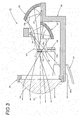
- Fig. 3 is a sectional view of the vehicle illumination lamp 10, which is similar to Fig. 2 , showing a state in which the second movable shade 28 is caused to shift from the state shown in Fig. 2 to a light uninterruptive position.
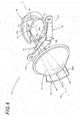
- Fig. 4 is a perspective view of the vehicle illumination lamp 10 which is in the state shown in Fig. 3 with main constituent elements removed.
- Fig. 5 is a sectional view of the vehicle illumination lamp 10, which is similar to Fig. 3 , showing a state in which the movable shade 18 is caused to shift from the state shown in Fig. 3 to the light interruptive position.
- Fig. 6 is a perspective view of the vehicle illumination lamp 10 which is in the state shown in Fig. 5 with the main constituent elements removed.
- the second light source 24 and the second reflector 26 are disposed in such a positional relationship that when the movable shade 18 shifts to the light uninterruptive position, light from the second light source 24 is reflected by the second reflector 26 so as to be shone to the front of the lamp without being allowed to be incident on the projection lens 12, while when the movable shade 18 shifts to the light interruptive position, the light from the second light source 24 is interrupted by the movable shade 18 so as not to be incident on the second reflector 26.
- the second light source 24 is made up of a light emitting element which is disposed to be oriented downwards in a position which lies further forwards than the light source 14 and further upwards than the optical axis Ax.
- this light source 24 is made up of a white light emitting diode having a horizontally elongated rectangular light emitting chip.
- the second reflector 26 is disposed further downwards than the optical axis Ax of the projection lens 12. Specifically, this second reflector 26 is disposed downwardly rightwards of the projection lens 12.
- a reflecting surface 26a of the second reflector 26 is formed into a paraboloidal surface whose focal point is constituted by the second light source 24 as a reference plane. The reflecting surface 26a is designed to reflect light from the second light source 24 as light which slightly diffuses.
- a third reflector 36 is disposed rearwards of the movable shade 18, and this third reflector 36 is designed to reflect light from the second light source 24 towards the projection lens 12.
- This third reflector 36 is disposed so as to cover the second light source 24 from therebelow.
- a reflecting surface 36a of this third reflector 36 is formed into a substantially ellipsoidal curved surface which has a major axis which is coaxial with the optical axis Ax and whose first focal point is constituted by a light emitting center of the second light source 24.
- An upper edge of the reflecting surface 36a is situated on the horizontal plane which contains the optical axis Ax.
- this reflecting surface 36a is designed to reflect light from the second light source 24 in such a form that the light substantially converges in a position lying obliquely upwards and forwards of the rear focal point F in a vertical plane and that the converging position is displaced forwards in a horizontal plane.
- the vehicle illumination lamp 10 is designed not only to form the high-beam variable luminous intensity distribution pattern but also to form selectively a low-beam luminous intensity distribution pattern.
- the second movable shade 28 is disposed between the reflector 16 and the projection lens 12.
- the second movable shade 28 is disposed near to the rear of the movable shade 18 so as to shift between a light interruptive position (a position indicated by solid lines in Fig. 1 ) where part of reflected light from the reflector 16 is interrupted and a light uninterruptive position (a position indicated by chain double-dashed lines in Fig. 1 ) where the interruption of the reflected light is released.
- This second movable shade 28 is a plate-shaped member which is disposed so as to lie along a vertical plane which intersects the optical axis Ax at right angles.
- the second movable shade 28 is rotatably supported on an actuator 44 at a left end portion thereof. Then, the second movable shade 28 is designed to shift between the light interruptive position and the light uninterruptive position when the actuator 44 is driven.
- the second movable shade 28 When shifting to the light interruptive position, the second movable shade 28 is disposed so that an upper edge 28a extends horizontally in a step-like fashion so as to pass through the rear focal point F of the projection lens 12.
- this vehicle illumination lamp 10 is switched to the low beam, only the light source 14 is turned on with the second movable shade 28 caused to shift to the light interruptive position, whereby a low-beam luminous intensity distribution pattern PL (refer to Fig. 8(a) ) is formed.
- the second light source 24 is additionally turned on with the second movable shade 28 caused to shift to the light uninterruptive position, whereby the high-beam luminous intensity distribution patterns PH1, PH2 (refer to Figs. 7(a), (b) ) are formed.
- the second light source 24 and the second reflector 26 are in such a positional relationship that light from the second light source 24 passes above the second movable shade 28 which has shifted to the light uninterruptive position to reach the second reflector 26.
- the second light source 24, the second and third reflectors 26, 36, the second movable shade 28 and the actuators 42, 44 are also supported on the holder 40.
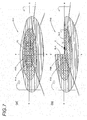
- Fig. 7 shows diagrams depicting in a perspective fashion the variable luminous intensity distribution patterns which are formed on an imaginary vertical aiming board which is disposed 25 m ahead of the vehicle illumination lamp 10, of which Fig. 7(a) shows the first variable luminous intensity distribution pattern and Fig. 7(b) shows the second variable luminous intensity distribution pattern.
- the first variable luminous intensity distribution pattern PH1 shown in Fig. 7(a) is the high-beam luminous intensity distribution pattern and is formed when the light source 14 and the second light source 24 are tuned on simultaneously with both the movable shade 18 and the second movable shade 28 having shifted to the light uninterruptive positions.
- This first variable luminous intensity distribution pattern PH1 is formed as a composite luminous intensity distribution pattern in which three luminous intensity distribution patterns P1A, P2, P3 are superposed one on another.
- the luminous intensity distribution pattern P1A is a luminous intensity distribution pattern which forms a basic configuration of the first variable luminous intensity distribution pattern PH1.
- the luminous intensity distribution pattern P1A is a luminous intensity distribution pattern which is formed by light which is emitted from the light source 14, is then reflected on the reflector 16 and is thereafter shone to the front of the lamp through the projection lens 12.
- the luminous intensity distribution pattern P2 is a relatively small luminous intensity distribution pattern which enhances a central luminous intensity of the first variable luminous intensity distribution pattern PH1 so as to ensure a sufficient far-field visibility.
- This luminous intensity distribution pattern P2 is a luminous intensity distribution pattern which is formed by light which is emitted from the second light source 24, is then reflected on the second reflector 26 and is thereafter shone to the front of the lamp without being allowed to be incident on the projection lens 12.
- a luminous intensity distribution pattern P3A is a luminous intensity distribution pattern which enhances the overall brightness of the first variable luminous intensity distribution pattern PH1.
- This luminous intensity distribution pattern P3A is a luminous intensity distribution pattern which is formed by light which is emitted from the second light source 24, is then reflected on the third reflector 36 and is thereafter shone to the front of the lamp through the projection lens 12.
- the second variable luminous intensity distribution pattern PH2 shown in Fig 7(b) is a luminous intensity distribution pattern in which part of the high-beam luminous intensity distribution pattern is eliminated and is formed when the light source 14 and the second light source 24 are turned on simultaneously with the second movable shade 28 and the movable shade 18 having shifted to the light uninterruptive position and the light interruptive position, respectively.
- a horizontal cut-off line CL3 and a vertical cut-off line CL4 are formed, respectively, by the upper edge 18a and the left edge 18b of the movable shade 18 which is in the light interruptive position to thereby form a luminous intensity distribution pattern in which a dark portion is formed at an upper right-hand side portion as a result of a corresponding portion of the first variable luminous intensity distribution pattern PH1 being eliminated.
- This second variable luminous intensity distribution pattern PH2 is formed as a composite luminous intensity distribution pattern in which two luminous intensity distribution patterns P1 B, P3B are superposed one on the other.
- the luminous intensity distribution pattern PB1 is a luminous intensity distribution pattern which forms a basic configuration of the second variable luminous intensity distribution pattern PH2.
- This luminous intensity distribution pattern PB1 is a luminous intensity distribution pattern which is formed by light which is emitted from the light source 14, is then reflected on the reflector 16 and is thereafter shone to the front of the lamp through the projection lens 12.
- This luminous intensity distribution pattern P1B has the horizontal cut-off line CL3 and the vertical cut-off line CL4.
- the luminous intensity distribution pattern P3B is a luminous intensity distribution pattern which enhances the overall brightness of the second variable luminous intensity distribution pattern PH2.
- This luminous intensity distribution pattern PH2 is a luminous intensity distribution pattern which is formed by light which is emitted from the second light source 24, is then reflected on the third reflector 36 and is thereafter shone to the front of the lamp through the projection lens 12.
- This luminous intensity distribution pattern P3B also has the horizontal cut-off line CL3 and the vertical cut-off line CL4.
- the luminous intensity distribution pattern P2 which contributes to the formation of the first variable luminous intensity distribution pattern PH1 does not contribute to the formation of the second variable luminous intensity distribution pattern PH2. This is because the light from the second light source 24 is interrupted by the movable shade 18 which is in the light interruptive position so as not to be incident on the second reflector 26.
- the low-beam luminous intensity distribution pattern PL is formed as a luminous intensity distribution pattern in which an upper portion of the luminous intensity distribution pattern P1A (refer to Fig. 8(b) ) which forms the basic configuration of the first variable luminous intensity distribution pattern PH1 is eliminated.
- This low-beam luminous intensity distribution pattern PL is a low-beam luminous intensity distribution pattern which is suitable for a left-hand traffic.
- Left and right horizontal cut-off lines CL1, CL2 are formed at an upper end portion thereof, and these left and right horizontal cut-off lines CL1, CL2 are different in level and are connected together via an elbow point E.
- These left and right cut-off lines CL1, CL2 which are different in level are formed by the upper edge 28a of the second movable shade 28 which has shifted to the light interruptive position.
- the vehicle illumination lamp 10 is configured as the projector type vehicle illumination lamp which forms the high-beam variable luminous intensity distribution pattern.
- the second light source 24 is disposed rearwards of the movable shade 18 which forms selectively the high-beam luminous intensity distribution pattern as the first variable luminous intensity distribution pattern PH1 and the second variable luminous intensity distribution pattern PH2 in which the part of the first variable luminous intensity distribution pattern is eliminated, and the second reflector 26 is disposed forwards of the movable shade 18.
- these second light source 24 and the second reflector 26 are in such a positional relationship that when the movable shade 18 shifts to the light uninterruptive position, the light from the second light source 24 is reflected by the second reflector 26 so as to be shone to the front of the lamp without being allowed to be incident on the projection lens 12, while when the movable shade 18 shifts to the light interruptive position, the light from the second light source 24 is interrupted by the movable shade 18 so as not to be incident on the second reflector 26.
- the first variable luminous intensity distribution pattern PH1 is formed when the movable shade 18 shifts to the light uninterruptive position, and as this occurs, the light from the second light source 24 is reflected by the second reflector 26 and is thereafter shone to the front of the lamp without being allowed to be incident on the projection lens 12. Therefore, the brightness of the first variable luminous intensity distribution pattern PH1 can be enhanced by a luminous intensity distribution pattern P2 which is formed by the light so shone to the front of the lamp.
- the second variable luminous intensity distribution pattern in which the part of the first variable luminous intensity distribution pattern PH1 is eliminated is formed when the movable shade 18 shifts to the light interruptive position.
- the light from the second light source 24 is interrupted by the movable shade 18 and is not allowed to be incident on the second reflector 26. Therefore, it becomes possible to prevent part of the luminous intensity distribution pattern P2 which is formed by the reflected light from the second reflector 26 from being formed so as to project to the upper right-hand side dark portion in the second variable luminous intensity distribution pattern which is formed as a result of the part of the first movable luminous intensity distribution pattern PH1 being eliminated. By so doing, it becomes possible to prevent the driver of the oncoming vehicle 2 from being dazzled.
- the brightness of the first variable luminous intensity distribution pattern PH1 can be enhanced without dazzling the driver of the oncoming vehicle 2.
- the third reflector 36 is disposed rearwards of the movable shade 18 which third reflector 36 is designed to reflect light from the second light source 24 towards the projection lens 12, and therefore, the brightness of the high-beam variable luminous intensity distribution patterns PH1, PH2 can be enhanced further by the luminous intensity distribution patterns P3A, P3B which are formed by the reflected light from that third reflector 36.
- the second movable shade 28 is disposed between the reflector 16 and the projection lens 12 which second movable shade 28 is designed to shift between the light interruptive position where part of the reflected light from the reflector 16 is interrupted so as to form the low-beam luminous intensity distribution pattern PL and the light uninterruptive position where the interruption of the reflected light is released, and therefore, the vehicle illumination lamp 10 can be switched between the low beam and the high beam.
- the second light source 24 and the second reflector 26 are disposed in such a positional relationship that the light from the second light source 24 reaches the second reflector 26 by passing above the second movable shade 28 which has shifted to the light uninterruptive position, and therefore, the movable shade 18 and the second movable shade 28 can be disposed without any difficulty.
- the light source 14 is made up of the light emitting element which is disposed to be oriented upwards on the optical axis Ax of the projection lens 12
- the second light source 24 is made up of the light emitting element which is disposed to be oriented downwards in the position lying further forwards than the light source 14 and further upwards than the optical axis Ax
- the second reflector 26 is disposed further downwards than the optical axis Ax. Therefore, the light source 14, the second light source 24 and the second reflector 26 can be disposed compact.
- the luminous intensity distribution pattern P2 which is formed by the light which is emitted from the second light source 24, is then reflected by the second reflector 26 and is thereafter shone to the front of the lamp without being allowed to be incident on the projection lens 12 is described as being formed as the relatively small luminous intensity distribution pattern which enhances the central luminous intensity of the first variable luminous intensity distribution pattern PH1 so as to ensure the sufficient far-field visibility.
- the luminous intensity distribution pattern P2 can also be formed as a relatively large luminous intensity distribution pattern.
- the second variable luminous intensity distribution pattern PH2 is described as being formed as the luminous intensity distribution pattern in which the upper right-hand side portion becomes the dark portion relative to the first variable luminous intensity distribution pattern PH1.
- the second variable luminous intensity distribution pattern can be formed as a luminous intensity distribution pattern in which an upper left-hand side portion becomes a dark portion relative to the first variable luminous intensity distribution pattern PH1. Then, by adopting this configuration, the dazzling of the driver of a preceding vehicle can be prevented when the second variable luminous intensity distribution pattern is formed.
- the vehicle illumination lamp 10 is described as being designed to form the low-beam luminous intensity distribution pattern suitable for the left-hand traffic as the low-beam luminous intensity distribution pattern PL.
- the same function and advantage as those of the embodiment can be obtained by adopting the same configuration as that of the embodiment.
Landscapes
- Engineering & Computer Science (AREA)
- General Engineering & Computer Science (AREA)
- Physics & Mathematics (AREA)
- Microelectronics & Electronic Packaging (AREA)
- Optics & Photonics (AREA)
- Geometry (AREA)
- Non-Portable Lighting Devices Or Systems Thereof (AREA)
Abstract
Description
- The present invention relates to a so-called projector type vehicle illumination lamp, and more particularly to a vehicle illumination lamp which is designed to form a variable luminous intensity distribution pattern.
- In general, in a projector type vehicle illumination lamp, light from a light source which is disposed further rearwards than a rear focal point of a projection lens is designed to be reflected towards the projection lens by a reflector.
-
JP-A-2011-65960 - Namely, in the vehicle illumination lamp described in
JP-A-2011-65960 - As done in the vehicle illumination lamp described in
JP-A-2011-65960 - In a vehicle illumination lamp like this, when a configuration is adopted in which a second light source and a second reflector which reflects to shine light from the second light source to the front of the lamp without allowing it to be incident on the projection lens are additionally provided, it becomes possible to increase the brightness of the high-beam luminous intensity distribution pattern.
- However, the following problem remains unsolved only by adopting that configuration alone. In particular, a luminous intensity distribution pattern that is formed by the reflected light from the second reflector is formed into a constant pattern irrespective of the position of the movable shade. Therefore, when the movable shade shifts to the light interruptive position to form the second variable luminous intensity distribution pattern, part of the luminous intensity distribution pattern formed by the reflected light from the second reflector projects to a dark portion which is formed in the second variable luminous intensity distribution pattern when it is formed as a result of the part of the high-beam luminous intensity distribution pattern being lost. This causes a problem that the driver of a preceding vehicle or an oncoming vehicle is dazzled by the resulting luminous intensity distribution pattern.
- The invention has been made in view of these situations, and an object thereof is to provide a projector type vehicle illumination lamp designed to form a high-beam variable luminous intensity distribution pattern in which when a second variable luminous intensity distribution pattern is formed which lacks part of a high-beam luminous intensity distribution pattern as a first variable luminous intensity distribution pattern, the brightness of the first variable luminous intensity distribution pattern can be enhanced without dazzling the driver of a preceding vehicle or an oncoming vehicle.
- In the present invention, this object is attained by adopting a configuration in which a second light source and a second reflector are additionally provided and then devising an optimum relationship between them.
- According to an aspect of the invention, there is provided a vehicle illumination lamp designed to form a high-beam variable luminous intensity distribution pattern, the vehicle illumination lamp comprising a projection lens, a light source which is disposed further rearwards than a rear focal point of the projection lens, a reflector which reflects light from the light source towards the projection lens, and a movable shade which is disposed between the reflector and the projection lens so as to shift between a light interruptive position where part of reflected light from the reflector is interrupted so as to eliminate part of a high-beam luminous intensity distribution pattern and a light uninterruptive position where the interruption of the reflected light is released, wherein a second light source is disposed rearwards of the movable shade and a second reflector is disposed forwards of the movable shade, and wherein the second light source and the second reflector are disposed in such a positional relationship that when the movable shade shifts to the light uninterruptive position, light from the second light source is reflected by the second reflector so as to be shone to the front of the lamp without being allowed to be incident on the projection lens, while when the movable shade shifts to the light interruptive position, the light from the second light source is interrupted by the movable shade so as not to be incident on the second reflector.
- The type of the "light source" is not limited to any specific type, and hence, for example, a light emitting portion of a discharge bulb, a filament of a halogen lamp or a light emitting chip of a light emitting element such as a light emitting diode can be adopted.
- The disposition of the "second light source" and the "second reflector" is not limited to any specific disposition as long as the second light source and the second reflector are disposed in such a positional relationship that when the movable shade shifts to the light uninterruptive position, light from the second light source is reflected by the second reflector so as to be shone to the front of the lamp without being allowed to be incident on the projection lens, while when the movable shade shifts to the light interruptive position, the light from the second light source is interrupted by the movable shade so as not to be incident on the second reflector. In disposing the second light source and the second reflector in such a positional relationship, as long as the driver of a preceding or oncoming vehicle is not dazzled, it is not necessarily required that light from the second light source is interrupted by the movable shade to such an extent that the light is totally prevented from being incident on the second reflector.
- As the configuration described above shows, in the vehicle illumination lamp according to the present invention configured as a projector type vehicle illumination lamp designed to form the high-beam variable luminous intensity distribution pattern, with the movable shade designed to selectively form the high-beam luminous intensity distribution pattern which is the first variable luminous intensity distribution pattern and the second variable luminous intensity distribution pattern in which part of the first variable luminous intensity distribution pattern is eliminated, the second light source is disposed rearwards of the movable shade, and the second reflector is disposed forwards of the movable shade. Additionally, the second light source and the second reflector are disposed in such a positional relationship that when the movable shade shifts to the light uninterruptive position, light from the second light source is reflected by the second reflector so as to be shone to the front of the lamp without being allowed to be incident on the projection lens, while when the movable shade shifts to the light interruptive position, the light from the second light source is interrupted by the movable shade so as not to be incident on the second reflector. Thus, the following function and advantage can be obtained.
- Namely, the first variable luminous intensity distribution pattern is formed when the movable shade shifts to the light uninterruptive position, and as this occurs, the light from the second light source is reflected by the second reflector and is thereafter shone to the front of the lamp without being allowed to be incident on the projection lens. Therefore, the brightness of the first variable luminous intensity distribution pattern can be enhanced by a luminous intensity distribution pattern which is formed by the light shone to the front of the lamp.
- On the other hand, the second variable luminous intensity distribution pattern in which part of the first variable luminous intensity distribution pattern is eliminated is formed when the movable shade shifts to the light interruptive position. As this occurs, the light from the second light source is interrupted by the movable shade and is not allowed to be incident on the second reflector. Therefore, it becomes possible to prevent part of the luminous intensity distribution pattern which is formed by the reflected light from the second reflector from being formed so as to project to a dark portion in the second variable luminous intensity distribution pattern which is formed as a result of the part of the first movable luminous intensity distribution pattern being eliminated. By so doing, it becomes possible to prevent the driver of a preceding or oncoming vehicle from being dazzled.
- In this way, in the present invention, in a projector type vehicle illumination lamp designed to form a high-beam variable luminous intensity distribution pattern, when the second variable luminous intensity distribution pattern is formed in which the part of the high-beam luminous intensity distribution pattern which is the first variable luminous intensity distribution pattern is eliminated, the brightness of the first variable luminous intensity distribution pattern can be enhanced without dazzling the driver of a preceding or oncoming vehicle.
- In the configuration described above, in the event that a third reflector is disposed rearwards of the movable shade which third reflector is designed to reflect light from the second light source towards the projection lens, the brightness of the high-beam variable luminous intensity distribution pattern can be enhanced further by a luminous intensity distribution pattern which is formed by the reflected light from the third reflector.
- In the configuration described above, in the event that a second movable shade is disposed between the reflector and the projection lens which second movable shade is designed to shift between a light interruptive position where part of reflected light from the reflector is interrupted so as to form a low-beam luminous intensity distribution pattern and a light uninterruptive position where the interruption of the reflected light is released, the vehicle illumination lamp can be switched between a low beam and a high beam. In this case, in the event that the second light source and the second reflector are disposed in such a positional relationship that light from the second light source reaches the second reflector by passing above the second movable shade which shifts to the light uninterruptive position, the movable shade and the second movable shade can be disposed without any difficulty.
- In the configuration described above, in the event that the light source is made up of a light emitting element which is disposed to be oriented upwards on or near to an optical axis of the projection lens, the second light source is made up of a light emitting element which is disposed to be oriented downwards in a position lying further forwards than the light source and further upwards than the optical axis, and the second reflector is disposed further downwards than the optical axis, the light source, the second light source and the second reflector can be disposed compact.
- Examples of the present invention will now be described in detail with reference to the accompanying drawings, in which:
-
Fig. 1 is a front view of a vehicle illumination lamp according to an embodiment of the invention, which shows a state in which a movable shade is in a light uninterruptive position and a second movable shade is in a light interruptive position. -
Fig. 2 is a sectional view of the vehicle illumination lamp taken along the line II-II inFig. 1 . -
Fig. 3 is a sectional view of the vehicle illumination lamp, which is similar toFig. 2 , showing a state in which the second movable shade is caused to shift from the state shown inFig. 2 to a light uninterruptive position. -
Fig. 4 is a perspective view of the vehicle illumination lamp which is in the state shown inFig. 3 with main constituent elements removed. -
Fig. 5 is a sectional view of the vehicle illumination lamp, which is similar toFig. 3 , showing a state in which the movable shade is caused to shift from the state shown inFig. 3 to a light interruptive position. -
Fig. 6 is a perspective view of the vehicle illumination lamp which is in the state shown inFig. 5 with the main constituent elements removed. -
Fig. 7 shows diagrams depicting in a perspective fashion variable luminous intensity distribution patterns which are formed on an imaginary vertical aiming board which is disposed 25 m ahead of the lamp, of whichFig. 7(a) shows a first variable luminous intensity distribution pattern andFig. 7(b) shows a second variable luminous intensity distribution pattern. -
Fig. 8 shows diagrams depicting the variable luminous intensity distribution patterns in a disassembled fashion by disassembling them into a plurality of luminous intensity distribution patterns. -
Fig. 1 is a front view of avehicle illumination lamp 10 according to an embodiment of the invention, which shows a state in which amovable shade 18 is in a light uninterruptive position and a secondmovable shade 28 is in a light interruptive position.Fig. 2 is a sectional view of thevehicle illumination lamp 10 which is taken along the line II-II inFig. 1 . - As shown in these figures, the
vehicle illumination lamp 10 according to the embodiment is configured as a projector type lamp unit and is designed to be incorporated in a lamp body, not shown, for use. - This
vehicle illumination lamp 10 is designed to form a high-beam variable luminous intensity distribution pattern. - To realize this, the
vehicle illumination lamp 10 includes aprojection lens 12, alight source 14 which is disposed further rearwards than a rear focal point F of theprojection lens 12, areflector 16 which reflects light from thelight source 14 towards theprojection lens 12, amovable shade 18 which is disposed between thereflector 16 and theprojection lens 12, and aholder 40 which supports these constituent components of thevehicle illumination lamp 10. - The
projection lens 12 is a planoconvex aspheric lens which is convex on a front surface and is flat on a rear surface thereof. Thisprojection lens 12 is supported on theholder 40 via alens holder 20. - The
light source 14 is made up of a light emitting element which is disposed to be oriented upwards on an optical axis Ax of theprojection lens 12. Specifically, thelight source 14 is made up of a white light emitting diode having a horizontally elongated rectangular light emitting chip. - The
reflector 16 is disposed so as to cover thelight source 14 from thereabove. A reflectingsurface 16a of thereflector 16 is formed into a substantially ellipsoidal curved surface which has a major axis which is coaxial with the optical axis Ax and whose first focal point is constituted by a light emitting center of thelight source 14. A lower edge of the reflectingsurface 16 is situated on a horizontal plane which contains the optical axis Ax. This reflectingsurface 16a is designed to reflect light from thelight source 14 in such a form that the light substantially converges near to the front of the rear focal point F in a vertical plane and that the converging position is displaced forwards in a horizontal plane. - The
movable shade 18 is disposed near to the front of the rear focal point F of theprojection lens 12 and is designed to shift between a light interruptive position (a position indicated by chain double-dashed lines inFig. 1 ) where part of reflected light from thereflector 16 is interrupted and a light uninterruptive position (a position indicated by solid lines inFig. 1 ) where the interruption of the reflected light is released. - This
movable shade 18 is a plate-shaped member which is disposed so as to lie along a vertical plane which intersects the optical axis Ax at right angles. Themovable shade 18 is supported on anactuator 42 at a right end portion (a left end portion when the lamp is seen from the front, this being true in the following diagrams) thereof so as to rotate about an axis Ax1 which extends in a front-to-rear direction of theactuator 42. Then, themovable shade 18 is designed to shift between the light interruptive position and the light uninterruptive position when theactuator 42 is driven. - When shifting to the light interruptive position, the
movable shade 18 is disposed so that anupper edge 18a extends horizontally near to a lower side of the optical axis Ax, while aleft edge 18b extends along a vertical plane which contains the optical axis Ax. - Additionally, in this
vehicle illumination lamp 10, when themovable shade 18 shifts to the light uninterruptive position, a high-beam variable luminous intensity distribution pattern is formed as a first variable luminous intensity distribution pattern PH1 (refer toFig. 7(a) ), while when themovable shade 18 shifts to the light interruptive position, a luminous intensity distribution pattern in which part of the high-beam luminous intensity distribution pattern is eliminated is formed as a second variable luminous intensity distribution pattern PH2 (refer toFig. 7(b) ). - As shown in
Figs. 1 and2 , asecond light source 24 is disposed rearwards of themovable shade 18, and asecond reflector 26 is disposed forwards of themovable shade 18. -
Fig. 3 is a sectional view of thevehicle illumination lamp 10, which is similar toFig. 2 , showing a state in which the secondmovable shade 28 is caused to shift from the state shown inFig. 2 to a light uninterruptive position. Additionally,Fig. 4 is a perspective view of thevehicle illumination lamp 10 which is in the state shown inFig. 3 with main constituent elements removed. - On the other hand,
Fig. 5 is a sectional view of thevehicle illumination lamp 10, which is similar toFig. 3 , showing a state in which themovable shade 18 is caused to shift from the state shown inFig. 3 to the light interruptive position. Additionally,Fig. 6 is a perspective view of thevehicle illumination lamp 10 which is in the state shown inFig. 5 with the main constituent elements removed. - As shown in these figures, the second
light source 24 and thesecond reflector 26 are disposed in such a positional relationship that when themovable shade 18 shifts to the light uninterruptive position, light from the secondlight source 24 is reflected by thesecond reflector 26 so as to be shone to the front of the lamp without being allowed to be incident on theprojection lens 12, while when themovable shade 18 shifts to the light interruptive position, the light from the secondlight source 24 is interrupted by themovable shade 18 so as not to be incident on thesecond reflector 26. - In order to realize this, the second
light source 24 is made up of a light emitting element which is disposed to be oriented downwards in a position which lies further forwards than thelight source 14 and further upwards than the optical axis Ax. Specifically, thislight source 24 is made up of a white light emitting diode having a horizontally elongated rectangular light emitting chip. - In addition, the
second reflector 26 is disposed further downwards than the optical axis Ax of theprojection lens 12. Specifically, thissecond reflector 26 is disposed downwardly rightwards of theprojection lens 12. A reflectingsurface 26a of thesecond reflector 26 is formed into a paraboloidal surface whose focal point is constituted by the secondlight source 24 as a reference plane. The reflectingsurface 26a is designed to reflect light from the secondlight source 24 as light which slightly diffuses. - A
third reflector 36 is disposed rearwards of themovable shade 18, and thisthird reflector 36 is designed to reflect light from the secondlight source 24 towards theprojection lens 12. - This
third reflector 36 is disposed so as to cover the secondlight source 24 from therebelow. A reflectingsurface 36a of thisthird reflector 36 is formed into a substantially ellipsoidal curved surface which has a major axis which is coaxial with the optical axis Ax and whose first focal point is constituted by a light emitting center of the secondlight source 24. An upper edge of the reflectingsurface 36a is situated on the horizontal plane which contains the optical axis Ax. Additionally, this reflectingsurface 36a is designed to reflect light from the secondlight source 24 in such a form that the light substantially converges in a position lying obliquely upwards and forwards of the rear focal point F in a vertical plane and that the converging position is displaced forwards in a horizontal plane. - The
vehicle illumination lamp 10 according to the embodiment is designed not only to form the high-beam variable luminous intensity distribution pattern but also to form selectively a low-beam luminous intensity distribution pattern. - In order to realize this, the second
movable shade 28 is disposed between thereflector 16 and theprojection lens 12. - The second
movable shade 28 is disposed near to the rear of themovable shade 18 so as to shift between a light interruptive position (a position indicated by solid lines inFig. 1 ) where part of reflected light from thereflector 16 is interrupted and a light uninterruptive position (a position indicated by chain double-dashed lines inFig. 1 ) where the interruption of the reflected light is released. - This second
movable shade 28 is a plate-shaped member which is disposed so as to lie along a vertical plane which intersects the optical axis Ax at right angles. The secondmovable shade 28 is rotatably supported on anactuator 44 at a left end portion thereof. Then, the secondmovable shade 28 is designed to shift between the light interruptive position and the light uninterruptive position when theactuator 44 is driven. - When shifting to the light interruptive position, the second
movable shade 28 is disposed so that anupper edge 28a extends horizontally in a step-like fashion so as to pass through the rear focal point F of theprojection lens 12. - Then, when this
vehicle illumination lamp 10 is switched to the low beam, only thelight source 14 is turned on with the secondmovable shade 28 caused to shift to the light interruptive position, whereby a low-beam luminous intensity distribution pattern PL (refer toFig. 8(a) ) is formed. On the other hand, when thevehicle illumination lamp 10 is switched to the high beam, the secondlight source 24 is additionally turned on with the secondmovable shade 28 caused to shift to the light uninterruptive position, whereby the high-beam luminous intensity distribution patterns PH1, PH2 (refer toFigs. 7(a), (b) ) are formed. - As this occurs, the second
light source 24 and thesecond reflector 26 are in such a positional relationship that light from the secondlight source 24 passes above the secondmovable shade 28 which has shifted to the light uninterruptive position to reach thesecond reflector 26. - The second
light source 24, the second andthird reflectors movable shade 28 and theactuators holder 40. -
Fig. 7 shows diagrams depicting in a perspective fashion the variable luminous intensity distribution patterns which are formed on an imaginary vertical aiming board which is disposed 25 m ahead of thevehicle illumination lamp 10, of whichFig. 7(a) shows the first variable luminous intensity distribution pattern andFig. 7(b) shows the second variable luminous intensity distribution pattern. - The first variable luminous intensity distribution pattern PH1 shown in
Fig. 7(a) is the high-beam luminous intensity distribution pattern and is formed when thelight source 14 and the secondlight source 24 are tuned on simultaneously with both themovable shade 18 and the secondmovable shade 28 having shifted to the light uninterruptive positions. - This first variable luminous intensity distribution pattern PH1 is formed as a composite luminous intensity distribution pattern in which three luminous intensity distribution patterns P1A, P2, P3 are superposed one on another.
- As shown in
Fig. 8(b) , the luminous intensity distribution pattern P1A is a luminous intensity distribution pattern which forms a basic configuration of the first variable luminous intensity distribution pattern PH1. The luminous intensity distribution pattern P1A is a luminous intensity distribution pattern which is formed by light which is emitted from thelight source 14, is then reflected on thereflector 16 and is thereafter shone to the front of the lamp through theprojection lens 12. - As shown in
Fig. 8(d) , the luminous intensity distribution pattern P2 is a relatively small luminous intensity distribution pattern which enhances a central luminous intensity of the first variable luminous intensity distribution pattern PH1 so as to ensure a sufficient far-field visibility. This luminous intensity distribution pattern P2 is a luminous intensity distribution pattern which is formed by light which is emitted from the secondlight source 24, is then reflected on thesecond reflector 26 and is thereafter shone to the front of the lamp without being allowed to be incident on theprojection lens 12. - As shown in
Fig. 8(e) , a luminous intensity distribution pattern P3A is a luminous intensity distribution pattern which enhances the overall brightness of the first variable luminous intensity distribution pattern PH1. This luminous intensity distribution pattern P3A is a luminous intensity distribution pattern which is formed by light which is emitted from the secondlight source 24, is then reflected on thethird reflector 36 and is thereafter shone to the front of the lamp through theprojection lens 12. - On the other hand, the second variable luminous intensity distribution pattern PH2 shown in
Fig 7(b) is a luminous intensity distribution pattern in which part of the high-beam luminous intensity distribution pattern is eliminated and is formed when thelight source 14 and the secondlight source 24 are turned on simultaneously with the secondmovable shade 28 and themovable shade 18 having shifted to the light uninterruptive position and the light interruptive position, respectively. - In the second variable luminous intensity distribution pattern PH2, a horizontal cut-off line CL3 and a vertical cut-off line CL4 are formed, respectively, by the
upper edge 18a and theleft edge 18b of themovable shade 18 which is in the light interruptive position to thereby form a luminous intensity distribution pattern in which a dark portion is formed at an upper right-hand side portion as a result of a corresponding portion of the first variable luminous intensity distribution pattern PH1 being eliminated. - This second variable luminous intensity distribution pattern PH2 is formed as a composite luminous intensity distribution pattern in which two luminous intensity distribution patterns P1 B, P3B are superposed one on the other.
- As shown in
Fig. 8(c) , the luminous intensity distribution pattern PB1 is a luminous intensity distribution pattern which forms a basic configuration of the second variable luminous intensity distribution pattern PH2. This luminous intensity distribution pattern PB1 is a luminous intensity distribution pattern which is formed by light which is emitted from thelight source 14, is then reflected on thereflector 16 and is thereafter shone to the front of the lamp through theprojection lens 12. This luminous intensity distribution pattern P1B has the horizontal cut-off line CL3 and the vertical cut-off line CL4. - As shown in
Fig. 8(f) , the luminous intensity distribution pattern P3B is a luminous intensity distribution pattern which enhances the overall brightness of the second variable luminous intensity distribution pattern PH2. This luminous intensity distribution pattern PH2 is a luminous intensity distribution pattern which is formed by light which is emitted from the secondlight source 24, is then reflected on thethird reflector 36 and is thereafter shone to the front of the lamp through theprojection lens 12. This luminous intensity distribution pattern P3B also has the horizontal cut-off line CL3 and the vertical cut-off line CL4. - In this second variable luminous intensity distribution pattern PH2, the luminous intensity distribution pattern P2 which contributes to the formation of the first variable luminous intensity distribution pattern PH1 does not contribute to the formation of the second variable luminous intensity distribution pattern PH2. This is because the light from the second
light source 24 is interrupted by themovable shade 18 which is in the light interruptive position so as not to be incident on thesecond reflector 26. - Consequently, in this second variable luminous intensity distribution pattern PH2, the upper right-hand side portion defined by the horizontal cut-off line CL3 and the vertical cut-off line CL4 is left as the dark portion, whereby the dazzling of the driver of an oncoming vehicle 2 is prevented.
- As shown in
Fig. 8(a) , the low-beam luminous intensity distribution pattern PL is formed as a luminous intensity distribution pattern in which an upper portion of the luminous intensity distribution pattern P1A (refer toFig. 8(b) ) which forms the basic configuration of the first variable luminous intensity distribution pattern PH1 is eliminated. - This low-beam luminous intensity distribution pattern PL is a low-beam luminous intensity distribution pattern which is suitable for a left-hand traffic. Left and right horizontal cut-off lines CL1, CL2 are formed at an upper end portion thereof, and these left and right horizontal cut-off lines CL1, CL2 are different in level and are connected together via an elbow point E. These left and right cut-off lines CL1, CL2 which are different in level are formed by the
upper edge 28a of the secondmovable shade 28 which has shifted to the light interruptive position. - Next, the function and advantage of the embodiment will be described.
- The
vehicle illumination lamp 10 according to the embodiment is configured as the projector type vehicle illumination lamp which forms the high-beam variable luminous intensity distribution pattern. In thevehicle illumination lamp 10, the secondlight source 24 is disposed rearwards of themovable shade 18 which forms selectively the high-beam luminous intensity distribution pattern as the first variable luminous intensity distribution pattern PH1 and the second variable luminous intensity distribution pattern PH2 in which the part of the first variable luminous intensity distribution pattern is eliminated, and thesecond reflector 26 is disposed forwards of themovable shade 18. Then, these secondlight source 24 and thesecond reflector 26 are in such a positional relationship that when themovable shade 18 shifts to the light uninterruptive position, the light from the secondlight source 24 is reflected by thesecond reflector 26 so as to be shone to the front of the lamp without being allowed to be incident on theprojection lens 12, while when themovable shade 18 shifts to the light interruptive position, the light from the secondlight source 24 is interrupted by themovable shade 18 so as not to be incident on thesecond reflector 26. Thus, the following function and advantage can be obtained. - Namely, the first variable luminous intensity distribution pattern PH1 is formed when the
movable shade 18 shifts to the light uninterruptive position, and as this occurs, the light from the secondlight source 24 is reflected by thesecond reflector 26 and is thereafter shone to the front of the lamp without being allowed to be incident on theprojection lens 12. Therefore, the brightness of the first variable luminous intensity distribution pattern PH1 can be enhanced by a luminous intensity distribution pattern P2 which is formed by the light so shone to the front of the lamp. - On the other hand, the second variable luminous intensity distribution pattern in which the part of the first variable luminous intensity distribution pattern PH1 is eliminated is formed when the
movable shade 18 shifts to the light interruptive position. As this occurs, the light from the secondlight source 24 is interrupted by themovable shade 18 and is not allowed to be incident on thesecond reflector 26. Therefore, it becomes possible to prevent part of the luminous intensity distribution pattern P2 which is formed by the reflected light from thesecond reflector 26 from being formed so as to project to the upper right-hand side dark portion in the second variable luminous intensity distribution pattern which is formed as a result of the part of the first movable luminous intensity distribution pattern PH1 being eliminated. By so doing, it becomes possible to prevent the driver of the oncoming vehicle 2 from being dazzled. - In this way, according to the embodiment of the invention, in the projector type
vehicle illumination lamp 10 designed to form the high-beam variable luminous intensity distribution pattern, when the second variable luminous intensity distribution pattern PH2 is formed in which the part of the high-beam luminous intensity distribution pattern which is the first variable luminous intensity distribution pattern PH1 is eliminated, the brightness of the first variable luminous intensity distribution pattern PH1 can be enhanced without dazzling the driver of the oncoming vehicle 2. - In addition, in the embodiment of the invention, the
third reflector 36 is disposed rearwards of themovable shade 18 whichthird reflector 36 is designed to reflect light from the secondlight source 24 towards theprojection lens 12, and therefore, the brightness of the high-beam variable luminous intensity distribution patterns PH1, PH2 can be enhanced further by the luminous intensity distribution patterns P3A, P3B which are formed by the reflected light from thatthird reflector 36. - Further, in the embodiment of the invention, the second
movable shade 28 is disposed between thereflector 16 and theprojection lens 12 which secondmovable shade 28 is designed to shift between the light interruptive position where part of the reflected light from thereflector 16 is interrupted so as to form the low-beam luminous intensity distribution pattern PL and the light uninterruptive position where the interruption of the reflected light is released, and therefore, thevehicle illumination lamp 10 can be switched between the low beam and the high beam. - In this case, in the embodiment of the invention, the second
light source 24 and thesecond reflector 26 are disposed in such a positional relationship that the light from the secondlight source 24 reaches thesecond reflector 26 by passing above the secondmovable shade 28 which has shifted to the light uninterruptive position, and therefore, themovable shade 18 and the secondmovable shade 28 can be disposed without any difficulty. - Additionally, in the embodiment of the invention, the
light source 14 is made up of the light emitting element which is disposed to be oriented upwards on the optical axis Ax of theprojection lens 12, the secondlight source 24 is made up of the light emitting element which is disposed to be oriented downwards in the position lying further forwards than thelight source 14 and further upwards than the optical axis Ax, and thesecond reflector 26 is disposed further downwards than the optical axis Ax. Therefore, thelight source 14, the secondlight source 24 and thesecond reflector 26 can be disposed compact. - In the embodiment of the invention, the luminous intensity distribution pattern P2 which is formed by the light which is emitted from the second
light source 24, is then reflected by thesecond reflector 26 and is thereafter shone to the front of the lamp without being allowed to be incident on theprojection lens 12 is described as being formed as the relatively small luminous intensity distribution pattern which enhances the central luminous intensity of the first variable luminous intensity distribution pattern PH1 so as to ensure the sufficient far-field visibility. However, instead of adopting this configuration, the luminous intensity distribution pattern P2 can also be formed as a relatively large luminous intensity distribution pattern. - In the embodiment of the invention, the second variable luminous intensity distribution pattern PH2 is described as being formed as the luminous intensity distribution pattern in which the upper right-hand side portion becomes the dark portion relative to the first variable luminous intensity distribution pattern PH1. However, in the event that a second movable shade is used which is disposed in such a position as to be laterally symmetrical with the second
movable shade 28 of the embodiment described above with respect to the optical axis Ax, the second variable luminous intensity distribution pattern can be formed as a luminous intensity distribution pattern in which an upper left-hand side portion becomes a dark portion relative to the first variable luminous intensity distribution pattern PH1. Then, by adopting this configuration, the dazzling of the driver of a preceding vehicle can be prevented when the second variable luminous intensity distribution pattern is formed. - In this embodiment, the
vehicle illumination lamp 10 is described as being designed to form the low-beam luminous intensity distribution pattern suitable for the left-hand traffic as the low-beam luminous intensity distribution pattern PL. However, even in the event that thevehicle illumination lamp 10 is designed to form a low-beam luminous intensity distribution pattern suitable for a right-hand traffic, the same function and advantage as those of the embodiment can be obtained by adopting the same configuration as that of the embodiment. - It should be noted that the numeric values shown as the specifications in the embodiment are only examples, and hence, those values may, of course, be set to different values as required.
Claims (4)
- A vehicle illumination lamp designed to form a high-beam variable luminous intensity distribution pattern, the vehicle illumination lamp comprising: a projection lens; a light source which is disposed further rearwards than a rear focal point of the projection lens; a reflector which reflects light from the light source towards the projection lens; and a movable shade which is disposed between the reflector and the projection lens so as to shift between a light interruptive position where part of reflected light from the reflector is interrupted so as to eliminate part of a high-beam luminous intensity distribution pattern and a light uninterruptive position where the interruption of the reflected light is released, wherein
a second light source is disposed rearwards of the movable shade and a second reflector is disposed forwards of the movable shade, and wherein
the second light source and the second reflector are disposed in such a positional relationship that when the movable shade shifts to the light uninterruptive position, light from the second light source is reflected by the second reflector so as to be shone to the front of the lamp without being allowed to be incident on the projection lens, while when the movable shade shifts to the light interruptive position, the light from the second light source is interrupted by the movable shade so as not to be incident on the second reflector. - A vehicle illumination lamp according to claim 1, wherein
a third reflector is disposed rearwards of the movable shade which third reflector is designed to reflect light from the second light source towards the projection lens. - A vehicle illumination lamp according to claim 2, wherein
a second movable shade is disposed between the reflector and the projection lens which second movable shade is designed to shift between a light interruptive position where part of reflected light from the reflector is interrupted so as to form a low-beam luminous intensity distribution pattern and a light uninterruptive position where the interruption of the reflected light is released, and wherein
the second light source and the second reflector are disposed in such a positional relationship that light from the second light source reaches the second reflector by passing above the second movable shade which shifts to the light uninterruptive position. - A vehicle illumination lamp according to any preceding claim, wherein
the light source is made up of a light emitting element which is disposed to be oriented upwards on or near to an optical axis of the projection lens, wherein
the second light source is made up of a light emitting element which is disposed to be oriented downwards in a position lying further forwards than the light source and further upwards than the optical axis, and wherein
the second reflector is disposed further downwards than the optical axis.
Applications Claiming Priority (1)
| Application Number | Priority Date | Filing Date | Title |
|---|---|---|---|
| JP2011152555A JP5717565B2 (en) | 2011-07-11 | 2011-07-11 | Lighting fixtures for vehicles |
Publications (3)
| Publication Number | Publication Date |
|---|---|
| EP2546568A2 true EP2546568A2 (en) | 2013-01-16 |
| EP2546568A3 EP2546568A3 (en) | 2015-02-25 |
| EP2546568B1 EP2546568B1 (en) | 2017-06-21 |
Family
ID=46420005
Family Applications (1)
| Application Number | Title | Priority Date | Filing Date |
|---|---|---|---|
| EP12174800.8A Not-in-force EP2546568B1 (en) | 2011-07-11 | 2012-07-03 | Vehicle illumination lamp |
Country Status (3)
| Country | Link |
|---|---|
| EP (1) | EP2546568B1 (en) |
| JP (1) | JP5717565B2 (en) |
| CN (1) | CN102878510B (en) |
Cited By (1)
| Publication number | Priority date | Publication date | Assignee | Title |
|---|---|---|---|---|
| DE102013202370A1 (en) * | 2013-02-14 | 2014-08-14 | Automotive Lighting Reutlingen Gmbh | Light module i.e. adaptive front lighting system light module, for headlight of motor car, has primary optics unit arranged to generate narrower light distribution focused to center of broader light distribution |
Families Citing this family (9)
| Publication number | Priority date | Publication date | Assignee | Title |
|---|---|---|---|---|
| JP6235237B2 (en) * | 2013-05-17 | 2017-11-22 | 株式会社小糸製作所 | Vehicle lighting |
| JP6132684B2 (en) * | 2013-07-10 | 2017-05-24 | 株式会社小糸製作所 | Vehicle lighting |
| JP6271183B2 (en) * | 2013-08-12 | 2018-01-31 | 株式会社小糸製作所 | Vehicle lighting |
| JP2016181351A (en) * | 2015-03-23 | 2016-10-13 | スタンレー電気株式会社 | Vehicular headlamp |
| JP2019102230A (en) * | 2017-11-30 | 2019-06-24 | 株式会社小糸製作所 | Vehicular lighting fixture |
| JP6968686B2 (en) * | 2017-12-22 | 2021-11-17 | スタンレー電気株式会社 | Vehicle lighting |
| CN110864265B (en) * | 2019-11-22 | 2022-06-21 | 芜湖安瑞光电有限公司 | Steering lamp reflector structure |
| EP3839327A1 (en) * | 2019-12-20 | 2021-06-23 | ZKW Group GmbH | Projection module for a motor vehicle headlight |
| JP7576524B2 (en) * | 2021-08-20 | 2024-10-31 | 株式会社小糸製作所 | Drawing lamp |
Citations (1)
| Publication number | Priority date | Publication date | Assignee | Title |
|---|---|---|---|---|
| JP2011065960A (en) | 2009-09-18 | 2011-03-31 | Koito Mfg Co Ltd | Vehicle headlight |
Family Cites Families (13)
| Publication number | Priority date | Publication date | Assignee | Title |
|---|---|---|---|---|
| JP3779173B2 (en) * | 2001-04-24 | 2006-05-24 | 株式会社小糸製作所 | Vehicle headlamp |
| JP3995919B2 (en) * | 2001-11-08 | 2007-10-24 | 株式会社小糸製作所 | Vehicle headlamp |
| JP4500273B2 (en) * | 2006-01-31 | 2010-07-14 | 株式会社小糸製作所 | Vehicle headlamp |
| JP4717696B2 (en) * | 2006-04-20 | 2011-07-06 | 株式会社小糸製作所 | Vehicle headlamp lamp unit |
| JP2008060021A (en) * | 2006-09-04 | 2008-03-13 | Koito Mfg Co Ltd | Vehicle headlamp |
| JP2008123753A (en) * | 2006-11-09 | 2008-05-29 | Koito Mfg Co Ltd | Vehicle lamp unit |
| JP2010161035A (en) * | 2009-01-09 | 2010-07-22 | Koito Mfg Co Ltd | Vehicle headlamp |
| JP2010262750A (en) * | 2009-04-30 | 2010-11-18 | Koito Mfg Co Ltd | Vehicle lighting |
| JP2011090839A (en) * | 2009-10-21 | 2011-05-06 | Koito Mfg Co Ltd | Vehicular headlamp |
| JP5468876B2 (en) * | 2009-11-10 | 2014-04-09 | 株式会社小糸製作所 | Optical unit |
| JP5410259B2 (en) * | 2009-12-10 | 2014-02-05 | 株式会社小糸製作所 | Lighting fixtures for vehicles |
| JP5398507B2 (en) * | 2009-12-16 | 2014-01-29 | 株式会社小糸製作所 | Vehicle headlamp device |
| JP5988594B2 (en) * | 2012-01-24 | 2016-09-07 | 株式会社小糸製作所 | Lamp unit and vehicle lamp |
-
2011
- 2011-07-11 JP JP2011152555A patent/JP5717565B2/en active Active
-
2012
- 2012-07-03 EP EP12174800.8A patent/EP2546568B1/en not_active Not-in-force
- 2012-07-11 CN CN201210240602.5A patent/CN102878510B/en not_active Expired - Fee Related
Patent Citations (1)
| Publication number | Priority date | Publication date | Assignee | Title |
|---|---|---|---|---|
| JP2011065960A (en) | 2009-09-18 | 2011-03-31 | Koito Mfg Co Ltd | Vehicle headlight |
Cited By (2)
| Publication number | Priority date | Publication date | Assignee | Title |
|---|---|---|---|---|
| DE102013202370A1 (en) * | 2013-02-14 | 2014-08-14 | Automotive Lighting Reutlingen Gmbh | Light module i.e. adaptive front lighting system light module, for headlight of motor car, has primary optics unit arranged to generate narrower light distribution focused to center of broader light distribution |
| DE102013202370B4 (en) * | 2013-02-14 | 2015-08-06 | Automotive Lighting Reutlingen Gmbh | Light module for a motor vehicle |
Also Published As
| Publication number | Publication date |
|---|---|
| CN102878510B (en) | 2015-05-13 |
| EP2546568A3 (en) | 2015-02-25 |
| EP2546568B1 (en) | 2017-06-21 |
| CN102878510A (en) | 2013-01-16 |
| JP2013020781A (en) | 2013-01-31 |
| JP5717565B2 (en) | 2015-05-13 |
Similar Documents
| Publication | Publication Date | Title |
|---|---|---|
| EP2546568B1 (en) | Vehicle illumination lamp | |
| US8425097B2 (en) | Lamp unit | |
| KR101423874B1 (en) | Vehicular lamp | |
| KR100986778B1 (en) | Automotive lighting unit | |
| JP5752982B2 (en) | Lighting fixtures for vehicles | |
| JP6235237B2 (en) | Vehicle lighting | |
| US7607811B2 (en) | Lighting unit | |
| JP5937310B2 (en) | Vehicle headlamp | |
| JP6448944B2 (en) | Vehicle lighting | |
| JP5897913B2 (en) | Lamp unit | |
| JP2005108554A (en) | Vehicle headlamp | |
| JP2011165600A (en) | Vehicular illumination lamp | |
| CN102466189A (en) | Vehicle lighting apparatus | |
| EP2172694B1 (en) | Vehicular lamp | |
| JP6935266B2 (en) | Vehicle lighting | |
| JP2017073344A (en) | Lighting appliance for vehicle | |
| KR102006319B1 (en) | Vehicle lighting unit | |
| JP2015146270A (en) | Vehicle lighting | |
| JP6495992B2 (en) | Vehicle lighting | |
| JP2015018702A (en) | Vehicle lighting | |
| JP2011090905A (en) | Vehicular headlight | |
| JP4315342B2 (en) | Vehicle headlamp | |
| JP5412314B2 (en) | Vehicle headlamp | |
| JP5897996B2 (en) | Vehicle lighting | |
| JP7234681B2 (en) | vehicle lamp |
Legal Events
| Date | Code | Title | Description |
|---|---|---|---|
| PUAI | Public reference made under article 153(3) epc to a published international application that has entered the european phase |
Free format text: ORIGINAL CODE: 0009012 |
|
| 17P | Request for examination filed |
Effective date: 20120703 |
|
| AK | Designated contracting states |
Kind code of ref document: A2 Designated state(s): AL AT BE BG CH CY CZ DE DK EE ES FI FR GB GR HR HU IE IS IT LI LT LU LV MC MK MT NL NO PL PT RO RS SE SI SK SM TR |
|
| AX | Request for extension of the european patent |
Extension state: BA ME |
|
| PUAL | Search report despatched |
Free format text: ORIGINAL CODE: 0009013 |
|
| AK | Designated contracting states |
Kind code of ref document: A3 Designated state(s): AL AT BE BG CH CY CZ DE DK EE ES FI FR GB GR HR HU IE IS IT LI LT LU LV MC MK MT NL NO PL PT RO RS SE SI SK SM TR |
|
| AX | Request for extension of the european patent |
Extension state: BA ME |
|
| RIC1 | Information provided on ipc code assigned before grant |
Ipc: F21S 8/10 20060101ALI20150119BHEP Ipc: F21V 14/08 20060101ALI20150119BHEP Ipc: F21S 8/12 20060101AFI20150119BHEP Ipc: F21V 7/00 20060101ALI20150119BHEP |
|
| GRAP | Despatch of communication of intention to grant a patent |
Free format text: ORIGINAL CODE: EPIDOSNIGR1 |
|
| STAA | Information on the status of an ep patent application or granted ep patent |
Free format text: STATUS: GRANT OF PATENT IS INTENDED |
|
| INTG | Intention to grant announced |
Effective date: 20170123 |
|
| GRAS | Grant fee paid |
Free format text: ORIGINAL CODE: EPIDOSNIGR3 |
|
| GRAA | (expected) grant |
Free format text: ORIGINAL CODE: 0009210 |
|
| STAA | Information on the status of an ep patent application or granted ep patent |
Free format text: STATUS: THE PATENT HAS BEEN GRANTED |
|
| AK | Designated contracting states |
Kind code of ref document: B1 Designated state(s): AL AT BE BG CH CY CZ DE DK EE ES FI FR GB GR HR HU IE IS IT LI LT LU LV MC MK MT NL NO PL PT RO RS SE SI SK SM TR |
|
| REG | Reference to a national code |
Ref country code: GB Ref legal event code: FG4D |
|
| REG | Reference to a national code |
Ref country code: CH Ref legal event code: EP |
|
| REG | Reference to a national code |
Ref country code: IE Ref legal event code: FG4D |
|
| REG | Reference to a national code |
Ref country code: FR Ref legal event code: PLFP Year of fee payment: 6 |
|
| REG | Reference to a national code |
Ref country code: AT Ref legal event code: REF Ref document number: 903292 Country of ref document: AT Kind code of ref document: T Effective date: 20170715 |
|
| REG | Reference to a national code |
Ref country code: DE Ref legal event code: R096 Ref document number: 602012033637 Country of ref document: DE |
|
| REG | Reference to a national code |
Ref country code: NL Ref legal event code: MP Effective date: 20170621 |
|
| PG25 | Lapsed in a contracting state [announced via postgrant information from national office to epo] |
Ref country code: GR Free format text: LAPSE BECAUSE OF FAILURE TO SUBMIT A TRANSLATION OF THE DESCRIPTION OR TO PAY THE FEE WITHIN THE PRESCRIBED TIME-LIMIT Effective date: 20170922 Ref country code: FI Free format text: LAPSE BECAUSE OF FAILURE TO SUBMIT A TRANSLATION OF THE DESCRIPTION OR TO PAY THE FEE WITHIN THE PRESCRIBED TIME-LIMIT Effective date: 20170621 Ref country code: NO Free format text: LAPSE BECAUSE OF FAILURE TO SUBMIT A TRANSLATION OF THE DESCRIPTION OR TO PAY THE FEE WITHIN THE PRESCRIBED TIME-LIMIT Effective date: 20170921 Ref country code: HR Free format text: LAPSE BECAUSE OF FAILURE TO SUBMIT A TRANSLATION OF THE DESCRIPTION OR TO PAY THE FEE WITHIN THE PRESCRIBED TIME-LIMIT Effective date: 20170621 Ref country code: LT Free format text: LAPSE BECAUSE OF FAILURE TO SUBMIT A TRANSLATION OF THE DESCRIPTION OR TO PAY THE FEE WITHIN THE PRESCRIBED TIME-LIMIT Effective date: 20170621 |
|
| PGFP | Annual fee paid to national office [announced via postgrant information from national office to epo] |
Ref country code: GB Payment date: 20170705 Year of fee payment: 6 |
|
| REG | Reference to a national code |
Ref country code: LT Ref legal event code: MG4D |
|
| REG | Reference to a national code |
Ref country code: AT Ref legal event code: MK05 Ref document number: 903292 Country of ref document: AT Kind code of ref document: T Effective date: 20170621 |
|
| REG | Reference to a national code |
Ref country code: DE Ref legal event code: R079 Ref document number: 602012033637 Country of ref document: DE Free format text: PREVIOUS MAIN CLASS: F21S0008120000 Ipc: F21S0041000000 |
|
| PG25 | Lapsed in a contracting state [announced via postgrant information from national office to epo] |
Ref country code: SE Free format text: LAPSE BECAUSE OF FAILURE TO SUBMIT A TRANSLATION OF THE DESCRIPTION OR TO PAY THE FEE WITHIN THE PRESCRIBED TIME-LIMIT Effective date: 20170621 Ref country code: RS Free format text: LAPSE BECAUSE OF FAILURE TO SUBMIT A TRANSLATION OF THE DESCRIPTION OR TO PAY THE FEE WITHIN THE PRESCRIBED TIME-LIMIT Effective date: 20170621 Ref country code: BG Free format text: LAPSE BECAUSE OF FAILURE TO SUBMIT A TRANSLATION OF THE DESCRIPTION OR TO PAY THE FEE WITHIN THE PRESCRIBED TIME-LIMIT Effective date: 20170921 Ref country code: LV Free format text: LAPSE BECAUSE OF FAILURE TO SUBMIT A TRANSLATION OF THE DESCRIPTION OR TO PAY THE FEE WITHIN THE PRESCRIBED TIME-LIMIT Effective date: 20170621 Ref country code: NL Free format text: LAPSE BECAUSE OF FAILURE TO SUBMIT A TRANSLATION OF THE DESCRIPTION OR TO PAY THE FEE WITHIN THE PRESCRIBED TIME-LIMIT Effective date: 20170621 |
|
| PG25 | Lapsed in a contracting state [announced via postgrant information from national office to epo] |
Ref country code: CZ Free format text: LAPSE BECAUSE OF FAILURE TO SUBMIT A TRANSLATION OF THE DESCRIPTION OR TO PAY THE FEE WITHIN THE PRESCRIBED TIME-LIMIT Effective date: 20170621 Ref country code: RO Free format text: LAPSE BECAUSE OF FAILURE TO SUBMIT A TRANSLATION OF THE DESCRIPTION OR TO PAY THE FEE WITHIN THE PRESCRIBED TIME-LIMIT Effective date: 20170621 Ref country code: AT Free format text: LAPSE BECAUSE OF FAILURE TO SUBMIT A TRANSLATION OF THE DESCRIPTION OR TO PAY THE FEE WITHIN THE PRESCRIBED TIME-LIMIT Effective date: 20170621 Ref country code: SK Free format text: LAPSE BECAUSE OF FAILURE TO SUBMIT A TRANSLATION OF THE DESCRIPTION OR TO PAY THE FEE WITHIN THE PRESCRIBED TIME-LIMIT Effective date: 20170621 Ref country code: EE Free format text: LAPSE BECAUSE OF FAILURE TO SUBMIT A TRANSLATION OF THE DESCRIPTION OR TO PAY THE FEE WITHIN THE PRESCRIBED TIME-LIMIT Effective date: 20170621 |
|
| PG25 | Lapsed in a contracting state [announced via postgrant information from national office to epo] |
Ref country code: ES Free format text: LAPSE BECAUSE OF FAILURE TO SUBMIT A TRANSLATION OF THE DESCRIPTION OR TO PAY THE FEE WITHIN THE PRESCRIBED TIME-LIMIT Effective date: 20170621 Ref country code: PL Free format text: LAPSE BECAUSE OF FAILURE TO SUBMIT A TRANSLATION OF THE DESCRIPTION OR TO PAY THE FEE WITHIN THE PRESCRIBED TIME-LIMIT Effective date: 20170621 Ref country code: IS Free format text: LAPSE BECAUSE OF FAILURE TO SUBMIT A TRANSLATION OF THE DESCRIPTION OR TO PAY THE FEE WITHIN THE PRESCRIBED TIME-LIMIT Effective date: 20171021 Ref country code: SM Free format text: LAPSE BECAUSE OF FAILURE TO SUBMIT A TRANSLATION OF THE DESCRIPTION OR TO PAY THE FEE WITHIN THE PRESCRIBED TIME-LIMIT Effective date: 20170621 Ref country code: IT Free format text: LAPSE BECAUSE OF FAILURE TO SUBMIT A TRANSLATION OF THE DESCRIPTION OR TO PAY THE FEE WITHIN THE PRESCRIBED TIME-LIMIT Effective date: 20170621 |
|
| REG | Reference to a national code |
Ref country code: CH Ref legal event code: PL |
|
| REG | Reference to a national code |
Ref country code: DE Ref legal event code: R097 Ref document number: 602012033637 Country of ref document: DE |
|
| PG25 | Lapsed in a contracting state [announced via postgrant information from national office to epo] |
Ref country code: MC Free format text: LAPSE BECAUSE OF FAILURE TO SUBMIT A TRANSLATION OF THE DESCRIPTION OR TO PAY THE FEE WITHIN THE PRESCRIBED TIME-LIMIT Effective date: 20170621 |
|
| REG | Reference to a national code |
Ref country code: IE Ref legal event code: MM4A |
|
| PLBE | No opposition filed within time limit |
Free format text: ORIGINAL CODE: 0009261 |
|
| STAA | Information on the status of an ep patent application or granted ep patent |
Free format text: STATUS: NO OPPOSITION FILED WITHIN TIME LIMIT |
|
| PG25 | Lapsed in a contracting state [announced via postgrant information from national office to epo] |
Ref country code: DK Free format text: LAPSE BECAUSE OF FAILURE TO SUBMIT A TRANSLATION OF THE DESCRIPTION OR TO PAY THE FEE WITHIN THE PRESCRIBED TIME-LIMIT Effective date: 20170621 Ref country code: LI Free format text: LAPSE BECAUSE OF NON-PAYMENT OF DUE FEES Effective date: 20170731 Ref country code: CH Free format text: LAPSE BECAUSE OF NON-PAYMENT OF DUE FEES Effective date: 20170731 Ref country code: IE Free format text: LAPSE BECAUSE OF NON-PAYMENT OF DUE FEES Effective date: 20170703 |
|
| 26N | No opposition filed |
Effective date: 20180322 |
|
| REG | Reference to a national code |
Ref country code: BE Ref legal event code: MM Effective date: 20170731 |
|
| REG | Reference to a national code |
Ref country code: FR Ref legal event code: PLFP Year of fee payment: 7 |
|
| PG25 | Lapsed in a contracting state [announced via postgrant information from national office to epo] |
Ref country code: LU Free format text: LAPSE BECAUSE OF NON-PAYMENT OF DUE FEES Effective date: 20170703 |
|
| PG25 | Lapsed in a contracting state [announced via postgrant information from national office to epo] |
Ref country code: BE Free format text: LAPSE BECAUSE OF NON-PAYMENT OF DUE FEES Effective date: 20170731 Ref country code: SI Free format text: LAPSE BECAUSE OF FAILURE TO SUBMIT A TRANSLATION OF THE DESCRIPTION OR TO PAY THE FEE WITHIN THE PRESCRIBED TIME-LIMIT Effective date: 20170621 |
|
| PGFP | Annual fee paid to national office [announced via postgrant information from national office to epo] |
Ref country code: FR Payment date: 20180612 Year of fee payment: 7 |
|
| PG25 | Lapsed in a contracting state [announced via postgrant information from national office to epo] |
Ref country code: MT Free format text: LAPSE BECAUSE OF NON-PAYMENT OF DUE FEES Effective date: 20170703 |
|
| PGFP | Annual fee paid to national office [announced via postgrant information from national office to epo] |
Ref country code: DE Payment date: 20180619 Year of fee payment: 7 |
|
| GBPC | Gb: european patent ceased through non-payment of renewal fee |
Effective date: 20180703 |
|
| PG25 | Lapsed in a contracting state [announced via postgrant information from national office to epo] |
Ref country code: GB Free format text: LAPSE BECAUSE OF NON-PAYMENT OF DUE FEES Effective date: 20180703 |
|
| PG25 | Lapsed in a contracting state [announced via postgrant information from national office to epo] |
Ref country code: HU Free format text: LAPSE BECAUSE OF FAILURE TO SUBMIT A TRANSLATION OF THE DESCRIPTION OR TO PAY THE FEE WITHIN THE PRESCRIBED TIME-LIMIT; INVALID AB INITIO Effective date: 20120703 |
|
| PG25 | Lapsed in a contracting state [announced via postgrant information from national office to epo] |
Ref country code: CY Free format text: LAPSE BECAUSE OF NON-PAYMENT OF DUE FEES Effective date: 20170621 |
|
| PG25 | Lapsed in a contracting state [announced via postgrant information from national office to epo] |
Ref country code: MK Free format text: LAPSE BECAUSE OF FAILURE TO SUBMIT A TRANSLATION OF THE DESCRIPTION OR TO PAY THE FEE WITHIN THE PRESCRIBED TIME-LIMIT Effective date: 20170621 |
|
| REG | Reference to a national code |
Ref country code: DE Ref legal event code: R119 Ref document number: 602012033637 Country of ref document: DE |
|
| PG25 | Lapsed in a contracting state [announced via postgrant information from national office to epo] |
Ref country code: TR Free format text: LAPSE BECAUSE OF FAILURE TO SUBMIT A TRANSLATION OF THE DESCRIPTION OR TO PAY THE FEE WITHIN THE PRESCRIBED TIME-LIMIT Effective date: 20170621 |
|
| PG25 | Lapsed in a contracting state [announced via postgrant information from national office to epo] |
Ref country code: DE Free format text: LAPSE BECAUSE OF NON-PAYMENT OF DUE FEES Effective date: 20200201 |
|
| PG25 | Lapsed in a contracting state [announced via postgrant information from national office to epo] |
Ref country code: PT Free format text: LAPSE BECAUSE OF FAILURE TO SUBMIT A TRANSLATION OF THE DESCRIPTION OR TO PAY THE FEE WITHIN THE PRESCRIBED TIME-LIMIT Effective date: 20170621 |
|
| PG25 | Lapsed in a contracting state [announced via postgrant information from national office to epo] |
Ref country code: FR Free format text: LAPSE BECAUSE OF NON-PAYMENT OF DUE FEES Effective date: 20190731 |
|
| PG25 | Lapsed in a contracting state [announced via postgrant information from national office to epo] |
Ref country code: AL Free format text: LAPSE BECAUSE OF FAILURE TO SUBMIT A TRANSLATION OF THE DESCRIPTION OR TO PAY THE FEE WITHIN THE PRESCRIBED TIME-LIMIT Effective date: 20170621 |