EP2546516B1 - Wind turbine auxiliary drive system - Google Patents
Wind turbine auxiliary drive system Download PDFInfo
- Publication number
- EP2546516B1 EP2546516B1 EP11382236.5A EP11382236A EP2546516B1 EP 2546516 B1 EP2546516 B1 EP 2546516B1 EP 11382236 A EP11382236 A EP 11382236A EP 2546516 B1 EP2546516 B1 EP 2546516B1
- Authority
- EP
- European Patent Office
- Prior art keywords
- wind turbine
- drive system
- lubricant
- auxiliary drive
- bearing ring
- Prior art date
- Legal status (The legal status is an assumption and is not a legal conclusion. Google has not performed a legal analysis and makes no representation as to the accuracy of the status listed.)
- Not-in-force
Links
- 239000000314 lubricant Substances 0.000 claims description 66
- 238000005096 rolling process Methods 0.000 claims description 27
- 238000005461 lubrication Methods 0.000 claims description 24
- 230000002787 reinforcement Effects 0.000 claims description 20
- 239000004519 grease Substances 0.000 claims description 12
- 238000011084 recovery Methods 0.000 description 9
- 239000012530 fluid Substances 0.000 description 3
- 238000005260 corrosion Methods 0.000 description 2
- 230000007797 corrosion Effects 0.000 description 2
- 238000007789 sealing Methods 0.000 description 2
- 238000010276 construction Methods 0.000 description 1
- 239000000356 contaminant Substances 0.000 description 1
- 238000011109 contamination Methods 0.000 description 1
- 230000000694 effects Effects 0.000 description 1
- 230000005611 electricity Effects 0.000 description 1
- JEIPFZHSYJVQDO-UHFFFAOYSA-N iron(III) oxide Inorganic materials O=[Fe]O[Fe]=O JEIPFZHSYJVQDO-UHFFFAOYSA-N 0.000 description 1
- 230000001050 lubricating effect Effects 0.000 description 1
- 238000012423 maintenance Methods 0.000 description 1
- 150000003839 salts Chemical class 0.000 description 1
- XLYOFNOQVPJJNP-UHFFFAOYSA-N water Substances O XLYOFNOQVPJJNP-UHFFFAOYSA-N 0.000 description 1
- 238000003466 welding Methods 0.000 description 1
Images



Classifications
-
- F—MECHANICAL ENGINEERING; LIGHTING; HEATING; WEAPONS; BLASTING
- F03—MACHINES OR ENGINES FOR LIQUIDS; WIND, SPRING, OR WEIGHT MOTORS; PRODUCING MECHANICAL POWER OR A REACTIVE PROPULSIVE THRUST, NOT OTHERWISE PROVIDED FOR
- F03D—WIND MOTORS
- F03D7/00—Controlling wind motors
- F03D7/02—Controlling wind motors the wind motors having rotation axis substantially parallel to the air flow entering the rotor
- F03D7/022—Adjusting aerodynamic properties of the blades
- F03D7/0224—Adjusting blade pitch
-
- F—MECHANICAL ENGINEERING; LIGHTING; HEATING; WEAPONS; BLASTING
- F03—MACHINES OR ENGINES FOR LIQUIDS; WIND, SPRING, OR WEIGHT MOTORS; PRODUCING MECHANICAL POWER OR A REACTIVE PROPULSIVE THRUST, NOT OTHERWISE PROVIDED FOR
- F03D—WIND MOTORS
- F03D80/00—Details, components or accessories not provided for in groups F03D1/00 - F03D17/00
- F03D80/70—Bearing or lubricating arrangements
-
- F—MECHANICAL ENGINEERING; LIGHTING; HEATING; WEAPONS; BLASTING
- F03—MACHINES OR ENGINES FOR LIQUIDS; WIND, SPRING, OR WEIGHT MOTORS; PRODUCING MECHANICAL POWER OR A REACTIVE PROPULSIVE THRUST, NOT OTHERWISE PROVIDED FOR
- F03D—WIND MOTORS
- F03D7/00—Controlling wind motors
- F03D7/02—Controlling wind motors the wind motors having rotation axis substantially parallel to the air flow entering the rotor
- F03D7/04—Automatic control; Regulation
-
- F—MECHANICAL ENGINEERING; LIGHTING; HEATING; WEAPONS; BLASTING
- F16—ENGINEERING ELEMENTS AND UNITS; GENERAL MEASURES FOR PRODUCING AND MAINTAINING EFFECTIVE FUNCTIONING OF MACHINES OR INSTALLATIONS; THERMAL INSULATION IN GENERAL
- F16C—SHAFTS; FLEXIBLE SHAFTS; ELEMENTS OR CRANKSHAFT MECHANISMS; ROTARY BODIES OTHER THAN GEARING ELEMENTS; BEARINGS
- F16C33/00—Parts of bearings; Special methods for making bearings or parts thereof
- F16C33/30—Parts of ball or roller bearings
- F16C33/58—Raceways; Race rings
- F16C33/583—Details of specific parts of races
- F16C33/586—Details of specific parts of races outside the space between the races, e.g. end faces or bore of inner ring
-
- F—MECHANICAL ENGINEERING; LIGHTING; HEATING; WEAPONS; BLASTING
- F16—ENGINEERING ELEMENTS AND UNITS; GENERAL MEASURES FOR PRODUCING AND MAINTAINING EFFECTIVE FUNCTIONING OF MACHINES OR INSTALLATIONS; THERMAL INSULATION IN GENERAL
- F16C—SHAFTS; FLEXIBLE SHAFTS; ELEMENTS OR CRANKSHAFT MECHANISMS; ROTARY BODIES OTHER THAN GEARING ELEMENTS; BEARINGS
- F16C33/00—Parts of bearings; Special methods for making bearings or parts thereof
- F16C33/30—Parts of ball or roller bearings
- F16C33/66—Special parts or details in view of lubrication
- F16C33/6603—Special parts or details in view of lubrication with grease as lubricant
- F16C33/6622—Details of supply and/or removal of the grease, e.g. purging grease
-
- F—MECHANICAL ENGINEERING; LIGHTING; HEATING; WEAPONS; BLASTING
- F05—INDEXING SCHEMES RELATING TO ENGINES OR PUMPS IN VARIOUS SUBCLASSES OF CLASSES F01-F04
- F05B—INDEXING SCHEME RELATING TO WIND, SPRING, WEIGHT, INERTIA OR LIKE MOTORS, TO MACHINES OR ENGINES FOR LIQUIDS COVERED BY SUBCLASSES F03B, F03D AND F03G
- F05B2260/00—Function
- F05B2260/70—Adjusting of angle of incidence or attack of rotating blades
- F05B2260/79—Bearing, support or actuation arrangements therefor
-
- F—MECHANICAL ENGINEERING; LIGHTING; HEATING; WEAPONS; BLASTING
- F05—INDEXING SCHEMES RELATING TO ENGINES OR PUMPS IN VARIOUS SUBCLASSES OF CLASSES F01-F04
- F05B—INDEXING SCHEME RELATING TO WIND, SPRING, WEIGHT, INERTIA OR LIKE MOTORS, TO MACHINES OR ENGINES FOR LIQUIDS COVERED BY SUBCLASSES F03B, F03D AND F03G
- F05B2260/00—Function
- F05B2260/98—Lubrication
-
- F—MECHANICAL ENGINEERING; LIGHTING; HEATING; WEAPONS; BLASTING
- F16—ENGINEERING ELEMENTS AND UNITS; GENERAL MEASURES FOR PRODUCING AND MAINTAINING EFFECTIVE FUNCTIONING OF MACHINES OR INSTALLATIONS; THERMAL INSULATION IN GENERAL
- F16C—SHAFTS; FLEXIBLE SHAFTS; ELEMENTS OR CRANKSHAFT MECHANISMS; ROTARY BODIES OTHER THAN GEARING ELEMENTS; BEARINGS
- F16C19/00—Bearings with rolling contact, for exclusively rotary movement
- F16C19/02—Bearings with rolling contact, for exclusively rotary movement with bearing balls essentially of the same size in one or more circular rows
- F16C19/04—Bearings with rolling contact, for exclusively rotary movement with bearing balls essentially of the same size in one or more circular rows for radial load mainly
- F16C19/08—Bearings with rolling contact, for exclusively rotary movement with bearing balls essentially of the same size in one or more circular rows for radial load mainly with two or more rows of balls
-
- F—MECHANICAL ENGINEERING; LIGHTING; HEATING; WEAPONS; BLASTING
- F16—ENGINEERING ELEMENTS AND UNITS; GENERAL MEASURES FOR PRODUCING AND MAINTAINING EFFECTIVE FUNCTIONING OF MACHINES OR INSTALLATIONS; THERMAL INSULATION IN GENERAL
- F16C—SHAFTS; FLEXIBLE SHAFTS; ELEMENTS OR CRANKSHAFT MECHANISMS; ROTARY BODIES OTHER THAN GEARING ELEMENTS; BEARINGS
- F16C2360/00—Engines or pumps
- F16C2360/31—Wind motors
-
- Y—GENERAL TAGGING OF NEW TECHNOLOGICAL DEVELOPMENTS; GENERAL TAGGING OF CROSS-SECTIONAL TECHNOLOGIES SPANNING OVER SEVERAL SECTIONS OF THE IPC; TECHNICAL SUBJECTS COVERED BY FORMER USPC CROSS-REFERENCE ART COLLECTIONS [XRACs] AND DIGESTS
- Y02—TECHNOLOGIES OR APPLICATIONS FOR MITIGATION OR ADAPTATION AGAINST CLIMATE CHANGE
- Y02E—REDUCTION OF GREENHOUSE GAS [GHG] EMISSIONS, RELATED TO ENERGY GENERATION, TRANSMISSION OR DISTRIBUTION
- Y02E10/00—Energy generation through renewable energy sources
- Y02E10/70—Wind energy
- Y02E10/72—Wind turbines with rotation axis in wind direction
Definitions
- the present invention relates to a wind turbine auxiliary drive system comprising a slew bearing and a lubrication system.
- the invention further relates to a wind turbine comprising the same.
- Wind turbines are commonly used to supply electricity into the electrical grid.
- Wind turbines generally comprise a rotor with a rotor hub and a plurality of blades.
- the rotor is set into rotation under the influence of the wind on the blades.
- the rotation of the rotor shaft drives the generator rotor either directly (“directly driven”) or through the use of a gearbox.
- Pitch systems are employed for adapting the position of a wind turbine blade to varying wind conditions.
- it is known to rotate the position of a blade along its longitudinal axis with respect to the rotor hub aided by a slew bearing.
- This slew bearing normally comprises an outer ring, an inner ring and, between these two rings, one or more rows of rolling elements which allow both rings to rotate relative to each other.
- this type of bearing may comprise a gear which meshes with a drive pinion.
- bearings normally include an annular chamber for retaining the rolling elements.
- the bearing chamber is normally built from two annular components known as raceways, more particularly outer and inner raceways having interior surfaces which form the radial walls of the bearing chamber.
- a lubrication fluid such as oil or grease, is normally contained within the bearing chamber in order to reduce the friction between the components and also to assist in the dissipation of heat.
- a circulation system may further be provided to inject and/or drain lubrication fluid into the bearing chamber.
- the loss of lubricating effectiveness may result in accelerated wear of the bearing elements.
- Document US7077630 describes the lubrication of a pitch system of a windmill wherein the spacing between the rolling bodies of the bearing and the teeth of the gear is very small and the bearing arrangement and the teeth are disposed in the volume region of a lubricant chamber.
- the lubricant chamber has the form of a circular ring which is coaxial with the bearing and the gear and which has two radially outer wall regions separated from each other by a gap which permits the rotary movement of the two wall regions with the rotor blade and the hub respectively.
- Such an arrangement is rather complicated and adds the extra weight of the lubricant chamber to the system.
- a blade bearing includes an inner ring that is firmly fixed to the rotor hub and an outer ring that is fitted with a toothing and is firmly connected to the rotor blade.
- a lubrication pinion is situated next to the drive pinion and underneath a cover means.
- cover means protects the lubrication pinion (and the drive pinion) against corrosion and contaminants. This is an expensive solution and the complete sealing of the cover may be difficult to achieve. If the sealing is not complete, the cover may not give an adequate protection against extreme temperatures and humidity.
- a wind turbine auxiliary drive system comprising a motor, a drive pinion, a bearing and a lubrication system, the bearing comprising an outer bearing ring, an inner bearing ring and, between these two bearing rings, one or more rows of rolling elements which allow both bearing rings to rotate relative to each other.
- the inner bearing ring has an inner side comprising a gear which meshes with the drive pinion, wherein a height of the gear in an axial direction is smaller than the height of the inner bearing ring such that a gearless portion is defined, and wherein at least one lubricant inlet and/or at least one lubricant outlet is arranged on said gearless portion.
- the lubrication of the contact areas between raceways and rolling elements arranged inside the bearing is carried out inside the blade root (some components may also be inside the hub) despite having a gear provided on an inner side of the inner bearing ring.
- This ensures the protection of lubrication components against water, rust and other contaminations without any additional means such as a cover.
- maintenance of the lubrication system may be relatively simple and cheap as it can be performed from inside the hub.
- At least one lubricant feeder and/or at least one lubricant collector may be directly fixed to the gearless portion. In others, it may be arranged on a reinforcement disc radially fixed to the gearless portion. These types of arrangement substantially avoid relative movement between the at least one lubricant feeder and/or lubricant collector and the bearing.
- lubrication components such as feeders and/or collectors, arranged on the reinforcement disc radially fixed to the gearless portion may be mounted above the gear.
- a drive motor may be mounted inside the hub and the drive pinion may mesh with the gear below the lubrication components. This way there will be substantially no interference between them when rotating the blade.
- a supporting arrangement for supporting lubrication components may be provided inside the inner bearing ring of the slew bearing in such a way that it traverses a bearing rotational axis.
- a pump and/or grease deposit may be arranged on said supporting arrangement.
- the connections, for power supply and electrical control of the pump and the grease deposit, can be arranged along the bearing rotational axis. This way, these connections will not be substantially affected by the rotational movement of the blade.
- grease circuits for grease or lubricant feeding may be machined in the inner bearing ring in such a way that the at least one lubricant inlet can be directly connected to the one or more rows of rolling elements. This way, the lubricant can reach the contact areas between raceways and internal rolling elements arranged inside them.
- Another aspect provides a wind turbine comprising at least one auxiliary drive system substantially as hereinbefore described.
- FIGS. 1 and 4 each show a wind turbine rotor according to different embodiments.
- the same reference numbers will be used for matching parts.
- the rotor may comprise a hub 10 to which a plurality of blades (not shown) may be rotatably attached.
- a pitch mechanism may be provided for rotating each blade along its longitudinal axis.
- the pitch mechanism may comprise a pitch bearing 20.
- the pitch bearing 20 may comprise an outer bearing ring 21 connected with the hub 10 and an inner bearing ring 22 connected with a blade (not shown).
- the hub 10 may comprise a flange 11 for mounting a drive pinion of a drive motor (neither shown). In some embodiments, the flange may form an integral piece with the hub.
- a reinforcement ring 23 may be radially fixed to an inner side (reference 222 of figure 7a ) of the inner bearing ring 22.
- the reinforcement ring 23 may be provided with axial through-bores 231.
- Lubricant injectors 32 may be fixed to the reinforcement ring 23, e.g. using screws, bolts, clamps or any other suitable fastening means in combination with said through-bores 231.
- the lubricant injectors 32 may be directly fixed to an inner side (reference 222 of figure 7a ) of the inner bearing ring 22.
- a supporting arrangement 30 for supporting lubrication components may be fixed to the reinforcement ring 23 in such a manner that the supporting arrangement 30 traverses a pitch bearing rotational axis 24.
- the supporting arrangement 30 may comprise two substantially parallel beams 31.
- Each beam 31 may be fixed to the reinforcement ring 23 by screws, bolts 311 or similar, e.g. one bolt at each end.
- the supporting arrangement may comprise a beam diametrically fixed to the reinforcement ring.
- the supporting arrangement may be directly fixed to the inner side of the inner bearing ring.
- Such a supporting arrangement 30 may support a lubrication pump 40.
- the pump 40 may be mounted on a platform 41 provided on the beams 31.
- the pump 40 may be arranged in such a manner that its main connection for power supply 42 may run along the bearing rotational axis 24, from the pump 40 to a front frame 12 on which the hub 10 may be rotatably mounted. And from the front frame, said main connection may continue towards a general electric system housed inside the nacelle (not shown). This way, it may not be affected by a pitch movement of the blade, i.e. the central line will not get tangled up with other components.
- the pump 40 can be used e.g. to pump lubricant through the lubricant injectors 32 into a feed line through inlets (reference 34 of figure 7a ) arranged on an inner side (reference 222 of figure 7a ) of the inner bearing ring 22.
- a lubricant deposit 43 may further be arranged on the supporting arrangement 30.
- the lubricant deposit 43 may be mounted on a platform 44 provided on the beams 31.
- the lubricant deposit 43 can be used, e.g., to store old lubricant recovered from inside the bearing. Such a lubricant recovery may need a recovery circuit, shown in figure 7c and lubricant extractors (reference 33a of figures 2a and 2b ).
- the lubricant deposit may be part of the pump assembly.
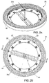
- Figure 2a shows a perspective of figure 1 viewed from the bottom, wherein the hub and the flange for mounting the drive pinion have been deleted.
- Figure 2b shows a rear view of figure 2a.
- Figures 2a and 2b show the lubricant injectors 32 and the lubricant extractors 33a fixed to the reinforcement ring 23.
- the lubricant extractors 33a may be directly fixed to an inner side (reference 222 of figure 7a ) of the inner bearing ring 22.
- the components of the lubrication circuit may all be arranged inside the blade root which ensures appropriate protection against corrosion. Furthermore, in case of wind turbines equipped with a temperature and humidity control inside the hub, e.g. for cold climates or desert climates, all the components housed inside the blade root may further be protected from extreme temperatures and humidity. These arrangements may also be suitable for offshore wind farms as no high salt content or humid air can come into contact with these components arranged inside the blade root.
- Figure 3 shows a cross-sectional view along line A-A of figure 2b .
- the outer bearing ring 21 and the inner bearing ring 22 may rotate relative to each other by means of two rows 23a, 23b of rolling elements.
- the rolling elements may be either balls or rollers and the bearing may comprise one or more rows of such rolling elements.
- the rolling elements may be housed inside a chamber defined by raceways 221 and 211 machined in the inner 22 and outer 21 bearing ring respectively.
- the inner bearing ring 22 may comprise an annular gear 223 radially on its inside, i.e. on the inner side (reference 222 of figure 7a ), to mesh with a drive pinion of a drive motor (neither shown) for driving the blade between different pitch positions about its longitudinal axis.
- a height h of the gear 223 in an axial direction may be smaller than a height H of the inner bearing ring 22, thus a gearless portion 224 may be defined on the inner side 222 of the inner bearing ring 22 (also shown in figure 7b ).
- the gear may be a partial gear or annular gear segments.
- a gear segment should be understood as a plurality of teeth shaped to be meshed with a drive pinion.
- Such gear segments or such a partial gear may be axially screwed or bolted to the reinforcement ring. This construction may facilitate the replacement of a deteriorated gear segment.
- Figure 4 shows another embodiment.
- the main difference with the embodiment shown in figures 1-3 is that the lubricant extractors and lubricant deposit have been replaced by lubricant collectors 33b such as bottles.
- lubricant collectors 33b such as bottles.
- the use of collectors or bottles is cheaper than the use of extractors, but the manual operation of emptying the bottles may be cumbersome as each bottle has to be emptied separately.
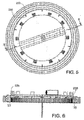
- Figure 5 shows a rear view of figure 4 , wherein the hub and the flange for mounting the drive pinion have been deleted.
- the reinforcement ring 23 may be provided with a first set of axial through-bores (reference 231 of figure 4 ) and a second set of axial through-bores 232.
- Lubricant injectors 32 may be screwed to the reinforcement ring 23 by means of the through-bores (reference 231 of figure 4 ) and the lubricant collectors or bottles 33b may be fixed to the reinforcement ring 23 by the through-bores 232.
- a tube 233 may connect each outlet (reference 35 of figure 6 ) with a lubricant collector or bottle (reference 33b of figures 4 or 6 ).
- Figure 6 shows a cross-sectional view along line B-B of figure 5 .
- the main difference with figure 3 is that the lubricant extractors and lubricant deposit have been replaced by lubricant collectors 33b such as bottles arranged on the reinforcement ring 23.
- lubricant collectors 33b such as bottles arranged on the reinforcement ring 23.
- Each collector 33b may be connected to an outlet 35 of the grease circuit by a tube 233 or similar.
- the reinforcement ring may be an annular disc comprising a central opening connecting an inside portion of the blade root with an inside portion of the hub.
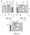
- Figures 7a, 7b and 7c show cross-sections of the bearing 20 with the lubricant circuits machined therein.
- the lubricant circuits may define a circulating system that injects and/or drain lubrication fluid into and from the bearing chamber defined by raceways 221, 211 machined in the inner 22 and outer 21 rings respectively. No reinforcement ring is shown in these cross-sections.
- the bearing 20 comprises two rows 23a, 23b of rolling elements.
- the lubricant circuits may be machined in the inner ring 22 from inlets 34 and outlets 35 arranged on the inner side 222 of the inner ring 22.
- the lubricant circuits may be defined by a combination of radial and axial holes. The axial holes may be closed by plugs 341 in order to avoid lubricant escape.
- Figures 7a and 7b show respective feed circuits
- figure 7a shows the feed circuit for the lower row 23b of rolling elements
- figure 7b shows the feed circuit for the upper row 23a of rolling elements in a bearing 20 comprising two rows 23a, 23b of rolling elements.
- Having a separate feed system for each row of rolling elements ensures a substantially equal distribution of lubricant between rows and avoids loss of charge effects.
- Figure 7c shows a recovery circuit arranged between the two rows 23a, 23b of rolling elements.
- Injectors 32 may shoot lubricant through inlets 34 arranged on the gearless portion 224 of the inner side 222 of the inner ring 22 to a feed duct 36. From said feed duct 36 the lubricant may be connected to the rows 23a, 23b of rolling elements by a first 37a or a second 37b duct respectively. Some of the inlets 34 may be connected to the first ducts 37a, others may be connected to the second ducts 37b. Alternatively, all inlets 34 may be connected to one passage that selectively supply the different rows 23a, 23b of rolling elements. This way, the inlet 34 can be directly connected to the different rows 23a, 23b of rolling elements thus reaching the contact areas between raceways 221, 211 and internal rolling elements arranged inside them.
- Figure 7c shows a recovery circuit, wherein the old lubricant may be removed by means of a return duct 38 that may be arranged substantially half-way between the two rows 23a, 23b of rolling elements.
- the return duct 38 may be further connected to a return line 39 that may end on an outlet 35 arranged on the gearless portion 224 of the inner side 222 of the inner ring 22.
- the outlets 35 may be connected to collectors (reference 33b of figures 4 or 6 ).
- they may be connected to lubricant extractors (reference 33a of figures 2a, 2b or 3 ) substantially as hereinbefore explained.
- Figures 8a and 8b show a grease feeding circuit for a manual or automatic system.
- Figure 8c shows a recovery circuit for an automatic system.
- the grease or lubricant initially stored in the pump 40, may be pumped to the injectors 32 that may be arranged in series.
- the clean lubricant of such feeding circuit may also pass through the extractors 33a which may also be arranged in series. Said clean lubricant may provide pressure to activate the extractors 33a.
- Figure 8b shows that the clean lubricant may further be injected inside the raceways by the injectors 32 (already filled with the lubricant originally stored inside the pump). Each injector 32 may feed only one inlet (reference 34 of figure 7a ).
- Figure 8c shows a recovery circuit for used lubricant that may comprise extractors 33a.
- the extractors 33a may also be arranged in series.
- the used lubricant may be accumulated in a grease deposit 43 substantially as hereinbefore explained.
- the lubricant can be brought to the bearing while the blades are rotating, i.e. when the rolling elements move inside the bearing. This way a better distribution of the lubricant on the raceways is ensured. This alternative is generally preferred in larger wind turbines.
- the feeding circuits and the automatic recovery circuit may be controlled by any suitable control means (not shown), which via an enabling switch (not shown) may activate the lubricant injectors or lubricant extractors whenever it is necessary. Also one or more valves (not shown) may be provided in the ducts.
- inlets and outlets are distributed around the circumference. Usually there are more inlets than outlets.
- injectors and extractors or collectors are fixed, directly or indirectly (by means of a reinforcement ring), these components will not have relative movements with the bearing which reduces the strain of the arrangement.
Landscapes
- Engineering & Computer Science (AREA)
- General Engineering & Computer Science (AREA)
- Mechanical Engineering (AREA)
- Life Sciences & Earth Sciences (AREA)
- Sustainable Development (AREA)
- Sustainable Energy (AREA)
- Chemical & Material Sciences (AREA)
- Combustion & Propulsion (AREA)
- Physics & Mathematics (AREA)
- Fluid Mechanics (AREA)
- Rolling Contact Bearings (AREA)
- Wind Motors (AREA)
Description
- The present invention relates to a wind turbine auxiliary drive system comprising a slew bearing and a lubrication system. The invention further relates to a wind turbine comprising the same.
- Modern wind turbines are commonly used to supply electricity into the electrical grid. Wind turbines generally comprise a rotor with a rotor hub and a plurality of blades. The rotor is set into rotation under the influence of the wind on the blades. The rotation of the rotor shaft drives the generator rotor either directly ("directly driven") or through the use of a gearbox.
- An important auxiliary system generally provided on wind turbines is the pitch system.
- Pitch systems are employed for adapting the position of a wind turbine blade to varying wind conditions. In this respect, it is known to rotate the position of a blade along its longitudinal axis with respect to the rotor hub aided by a slew bearing.
- This slew bearing normally comprises an outer ring, an inner ring and, between these two rings, one or more rows of rolling elements which allow both rings to rotate relative to each other. In some cases this type of bearing may comprise a gear which meshes with a drive pinion.
- These bearings normally include an annular chamber for retaining the rolling elements. The bearing chamber is normally built from two annular components known as raceways, more particularly outer and inner raceways having interior surfaces which form the radial walls of the bearing chamber. A lubrication fluid, such as oil or grease, is normally contained within the bearing chamber in order to reduce the friction between the components and also to assist in the dissipation of heat. A circulation system may further be provided to inject and/or drain lubrication fluid into the bearing chamber.
- The loss of lubricating effectiveness may result in accelerated wear of the bearing elements.
- Thus, proper lubrication of the bearings must be provided and maintained, in particular lubrication of the contact areas between raceways and rolling elements arranged inside the bearing chamber. Such lubrication may be particularly complicated and expensive due to the complicated accessibility of such contact areas.
- Document
US7077630 describes the lubrication of a pitch system of a windmill wherein the spacing between the rolling bodies of the bearing and the teeth of the gear is very small and the bearing arrangement and the teeth are disposed in the volume region of a lubricant chamber. The lubricant chamber has the form of a circular ring which is coaxial with the bearing and the gear and which has two radially outer wall regions separated from each other by a gap which permits the rotary movement of the two wall regions with the rotor blade and the hub respectively. Such an arrangement is rather complicated and adds the extra weight of the lubricant chamber to the system. - Document
US7470111 describes a wind turbine wherein a blade bearing includes an inner ring that is firmly fixed to the rotor hub and an outer ring that is fitted with a toothing and is firmly connected to the rotor blade. A lubrication pinion is situated next to the drive pinion and underneath a cover means. Such cover means protects the lubrication pinion (and the drive pinion) against corrosion and contaminants. This is an expensive solution and the complete sealing of the cover may be difficult to achieve. If the sealing is not complete, the cover may not give an adequate protection against extreme temperatures and humidity. - Other prior art examples can be found in
US 2010135808 andDE102006050765 . - Thus, there still exists a need to provide a cost-effective lubrication system for lubrication of the contact areas between raceways and internal rolling elements arranged inside the bearing chamber.
- In a first aspect, a wind turbine auxiliary drive system is provided that comprises a motor, a drive pinion, a bearing and a lubrication system, the bearing comprising an outer bearing ring, an inner bearing ring and, between these two bearing rings, one or more rows of rolling elements which allow both bearing rings to rotate relative to each other. The inner bearing ring has an inner side comprising a gear which meshes with the drive pinion, wherein a height of the gear in an axial direction is smaller than the height of the inner bearing ring such that a gearless portion is defined, and wherein at least one lubricant inlet and/or at least one lubricant outlet is arranged on said gearless portion.
- According to this aspect, the lubrication of the contact areas between raceways and rolling elements arranged inside the bearing is carried out inside the blade root (some components may also be inside the hub) despite having a gear provided on an inner side of the inner bearing ring. This ensures the protection of lubrication components against water, rust and other contaminations without any additional means such as a cover. Also, maintenance of the lubrication system may be relatively simple and cheap as it can be performed from inside the hub.
- In some embodiments, at least one lubricant feeder and/or at least one lubricant collector may be directly fixed to the gearless portion. In others, it may be arranged on a reinforcement disc radially fixed to the gearless portion. These types of arrangement substantially avoid relative movement between the at least one lubricant feeder and/or lubricant collector and the bearing.
- Further, lubrication components such as feeders and/or collectors, arranged on the reinforcement disc radially fixed to the gearless portion may be mounted above the gear. And a drive motor may be mounted inside the hub and the drive pinion may mesh with the gear below the lubrication components. This way there will be substantially no interference between them when rotating the blade.
- According to the invention, a supporting arrangement for supporting lubrication components may be provided inside the inner bearing ring of the slew bearing in such a way that it traverses a bearing rotational axis. In such cases a pump and/or grease deposit may be arranged on said supporting arrangement. The connections, for power supply and electrical control of the pump and the grease deposit, can be arranged along the bearing rotational axis. This way, these connections will not be substantially affected by the rotational movement of the blade.
- In some embodiments, grease circuits for grease or lubricant feeding may be machined in the inner bearing ring in such a way that the at least one lubricant inlet can be directly connected to the one or more rows of rolling elements. This way, the lubricant can reach the contact areas between raceways and internal rolling elements arranged inside them.
- Another aspect provides a wind turbine comprising at least one auxiliary drive system substantially as hereinbefore described.
- Additional objects, advantages and features of embodiments of the invention will become apparent to those skilled in the art upon examination of the description, or may be learned by practice of the invention.
- Particular embodiments of the present invention will be described in the following by way of non-limiting examples, with reference to the appended drawings, in which:
-
Figure 1 shows a wind turbine rotor according to an embodiment; -
Figures 2a-2b show bottom views offigure 1 ; -
Figure 3 shows a cross-section along line A-A offigure 2b ; -
Figure 4 shows a wind turbine rotor according to another embodiment; -
Figure 5 shows a bottom view offigure 4 ; -
Figure 6 shows a cross-section along line B-B offigure 5 ; -
Figures 7a, 7b and 7c show a partial cross-section of different embodiments of a slew bearing and its lubricant circuits; -
Figures 8a-8c show a schematic view of different embodiments of feeding and collecting circuits. -
Figures 1 and4 each show a wind turbine rotor according to different embodiments. The same reference numbers will be used for matching parts. The rotor may comprise ahub 10 to which a plurality of blades (not shown) may be rotatably attached. A pitch mechanism may be provided for rotating each blade along its longitudinal axis. The pitch mechanism may comprise a pitch bearing 20. Thepitch bearing 20 may comprise anouter bearing ring 21 connected with thehub 10 and aninner bearing ring 22 connected with a blade (not shown). Thehub 10 may comprise aflange 11 for mounting a drive pinion of a drive motor (neither shown). In some embodiments, the flange may form an integral piece with the hub. In others it may be a separate piece fixed to the hub by welding or by fastening means such as screws, bolts or similar. Further, areinforcement ring 23 may be radially fixed to an inner side (reference 222 offigure 7a ) of theinner bearing ring 22. - The
reinforcement ring 23 may be provided with axial through-bores 231.Lubricant injectors 32 may be fixed to thereinforcement ring 23, e.g. using screws, bolts, clamps or any other suitable fastening means in combination with said through-bores 231. Alternatively, thelubricant injectors 32 may be directly fixed to an inner side (reference 222 offigure 7a ) of theinner bearing ring 22. - Further, a supporting
arrangement 30 for supporting lubrication components may be fixed to thereinforcement ring 23 in such a manner that the supportingarrangement 30 traverses a pitch bearingrotational axis 24. The supportingarrangement 30 may comprise two substantially parallel beams 31. Eachbeam 31 may be fixed to thereinforcement ring 23 by screws,bolts 311 or similar, e.g. one bolt at each end. In alternative embodiments, the supporting arrangement may comprise a beam diametrically fixed to the reinforcement ring. In yet further embodiments, the supporting arrangement may be directly fixed to the inner side of the inner bearing ring. - Such a supporting
arrangement 30 may support alubrication pump 40. In some cases, thepump 40 may be mounted on aplatform 41 provided on thebeams 31. Thepump 40 may be arranged in such a manner that its main connection for power supply 42 may run along the bearingrotational axis 24, from thepump 40 to afront frame 12 on which thehub 10 may be rotatably mounted. And from the front frame, said main connection may continue towards a general electric system housed inside the nacelle (not shown). This way, it may not be affected by a pitch movement of the blade, i.e. the central line will not get tangled up with other components. Thepump 40 can be used e.g. to pump lubricant through thelubricant injectors 32 into a feed line through inlets (reference 34 offigure 7a ) arranged on an inner side (reference 222 offigure 7a ) of theinner bearing ring 22. - In the embodiment shown in
figure 1 alubricant deposit 43 may further be arranged on the supportingarrangement 30. In some cases, thelubricant deposit 43 may be mounted on aplatform 44 provided on thebeams 31. Thelubricant deposit 43 can be used, e.g., to store old lubricant recovered from inside the bearing. Such a lubricant recovery may need a recovery circuit, shown infigure 7c and lubricant extractors (reference 33a offigures 2a and 2b ). In alternative embodiments, the lubricant deposit may be part of the pump assembly. -
Figure 2a shows a perspective offigure 1 viewed from the bottom, wherein the hub and the flange for mounting the drive pinion have been deleted.Figure 2b shows a rear view offigure 2a. Figures 2a and 2b show thelubricant injectors 32 and thelubricant extractors 33a fixed to thereinforcement ring 23. In alternative embodiments, thelubricant extractors 33a may be directly fixed to an inner side (reference 222 offigure 7a ) of theinner bearing ring 22. - Thus, the components of the lubrication circuit may all be arranged inside the blade root which ensures appropriate protection against corrosion. Furthermore, in case of wind turbines equipped with a temperature and humidity control inside the hub, e.g. for cold climates or desert climates, all the components housed inside the blade root may further be protected from extreme temperatures and humidity. These arrangements may also be suitable for offshore wind farms as no high salt content or humid air can come into contact with these components arranged inside the blade root.
-
Figure 3 shows a cross-sectional view along line A-A offigure 2b . Theouter bearing ring 21 and theinner bearing ring 22 may rotate relative to each other by means of tworows raceways inner bearing ring 22 may comprise anannular gear 223 radially on its inside, i.e. on the inner side (reference 222 offigure 7a ), to mesh with a drive pinion of a drive motor (neither shown) for driving the blade between different pitch positions about its longitudinal axis. - A height h of the
gear 223 in an axial direction may be smaller than a height H of theinner bearing ring 22, thus agearless portion 224 may be defined on theinner side 222 of the inner bearing ring 22 (also shown infigure 7b ). - In alternative embodiments the gear may be a partial gear or annular gear segments. A gear segment should be understood as a plurality of teeth shaped to be meshed with a drive pinion. Such gear segments or such a partial gear may be axially screwed or bolted to the reinforcement ring. This construction may facilitate the replacement of a deteriorated gear segment.
-
Figure 4 shows another embodiment. The main difference with the embodiment shown infigures 1-3 is that the lubricant extractors and lubricant deposit have been replaced bylubricant collectors 33b such as bottles. The use of collectors or bottles is cheaper than the use of extractors, but the manual operation of emptying the bottles may be cumbersome as each bottle has to be emptied separately. -
Figure 5 shows a rear view offigure 4 , wherein the hub and the flange for mounting the drive pinion have been deleted. Thereinforcement ring 23 may be provided with a first set of axial through-bores (reference 231 offigure 4 ) and a second set of axial through-bores 232.Lubricant injectors 32 may be screwed to thereinforcement ring 23 by means of the through-bores (reference 231 offigure 4 ) and the lubricant collectors orbottles 33b may be fixed to thereinforcement ring 23 by the through-bores 232. Atube 233 may connect each outlet (reference 35 offigure 6 ) with a lubricant collector or bottle (reference 33b offigures 4 or6 ). -
Figure 6 shows a cross-sectional view along line B-B offigure 5 . The main difference withfigure 3 is that the lubricant extractors and lubricant deposit have been replaced bylubricant collectors 33b such as bottles arranged on thereinforcement ring 23. Eachcollector 33b may be connected to anoutlet 35 of the grease circuit by atube 233 or similar. - In alternative embodiments, the reinforcement ring may be an annular disc comprising a central opening connecting an inside portion of the blade root with an inside portion of the hub.
-
Figures 7a, 7b and 7c show cross-sections of the bearing 20 with the lubricant circuits machined therein. The lubricant circuits may define a circulating system that injects and/or drain lubrication fluid into and from the bearing chamber defined byraceways bearing 20 comprises tworows inner ring 22 frominlets 34 andoutlets 35 arranged on theinner side 222 of theinner ring 22. The lubricant circuits may be defined by a combination of radial and axial holes. The axial holes may be closed byplugs 341 in order to avoid lubricant escape. -
Figures 7a and 7b show respective feed circuits,figure 7a shows the feed circuit for thelower row 23b of rolling elements andfigure 7b shows the feed circuit for theupper row 23a of rolling elements in abearing 20 comprising tworows Figure 7c shows a recovery circuit arranged between the tworows -
Injectors 32 may shoot lubricant throughinlets 34 arranged on thegearless portion 224 of theinner side 222 of theinner ring 22 to afeed duct 36. From saidfeed duct 36 the lubricant may be connected to therows inlets 34 may be connected to thefirst ducts 37a, others may be connected to thesecond ducts 37b. Alternatively, allinlets 34 may be connected to one passage that selectively supply thedifferent rows inlet 34 can be directly connected to thedifferent rows raceways -
Figure 7c shows a recovery circuit, wherein the old lubricant may be removed by means of areturn duct 38 that may be arranged substantially half-way between the tworows return duct 38 may be further connected to areturn line 39 that may end on anoutlet 35 arranged on thegearless portion 224 of theinner side 222 of theinner ring 22. In some cases theoutlets 35 may be connected to collectors (reference 33b offigures 4 or6 ). In others they may be connected to lubricant extractors (reference 33a offigures 2a, 2b or3 ) substantially as hereinbefore explained. -
Figures 8a and 8b show a grease feeding circuit for a manual or automatic system.Figure 8c shows a recovery circuit for an automatic system. - In
figure 8a the grease or lubricant, initially stored in thepump 40, may be pumped to theinjectors 32 that may be arranged in series. In case of an automatic system, the clean lubricant of such feeding circuit may also pass through theextractors 33a which may also be arranged in series. Said clean lubricant may provide pressure to activate theextractors 33a. -
Figure 8b shows that the clean lubricant may further be injected inside the raceways by the injectors 32 (already filled with the lubricant originally stored inside the pump). Eachinjector 32 may feed only one inlet (reference 34 offigure 7a ). -
Figure 8c shows a recovery circuit for used lubricant that may compriseextractors 33a. Theextractors 33a may also be arranged in series. In some embodiments, the used lubricant may be accumulated in agrease deposit 43 substantially as hereinbefore explained. - In the case of a manual system there may not be a recovery circuit as such, but the recovery of used lubricant may be carried out in a passive manner. The used lubricant moves (by pressure) towards the bottles. And, when the bottles are filled they may be manually emptied.
- In some cases, the lubricant can be brought to the bearing while the blades are rotating, i.e. when the rolling elements move inside the bearing. This way a better distribution of the lubricant on the raceways is ensured. This alternative is generally preferred in larger wind turbines.
- The feeding circuits and the automatic recovery circuit may be controlled by any suitable control means (not shown), which via an enabling switch (not shown) may activate the lubricant injectors or lubricant extractors whenever it is necessary. Also one or more valves (not shown) may be provided in the ducts.
- In general, the inlets and outlets are distributed around the circumference. Usually there are more inlets than outlets.
- Further, since the injectors and extractors or collectors are fixed, directly or indirectly (by means of a reinforcement ring), these components will not have relative movements with the bearing which reduces the strain of the arrangement.
Claims (12)
- Wind turbine auxiliary drive system comprising a motor, a drive pinion and a bearing (20), the bearing (20) comprising an outer bearing ring (21), an inner bearing ring (22) and, between these two bearing rings, one or more rows of rolling elements (23a; 23b) which allow both bearing rings to rotate relative to each other, the inner bearing ring (22) having an inner side (222) comprising a gear (223) which meshes with the drive pinion, wherein a height (h) of the gear (223) in an axial direction is smaller than the height (H) of the inner bearing ring (22) such that a gearless portion (224) is defined characterized in that it comprises a lubrication system wherein at least one lubricant inlet (35) and/or at least one lubricant outlet (34) is arranged on the gearless portion (224), and wherein a supporting arrangement (30) for supporting lubrication components is provided inside the inner bearing ring (22) of the bearing (20) in such a way that it traverses a bearing rotational axis (24).
- Wind turbine auxiliary drive system according to claim 1, wherein at least one lubricant feeder (32) and/or at least one lubricant collector (33a; 33b) is directly fixed to said gearless portion (224).
- Wind turbine auxiliary drive system according to claim 1, wherein at least one lubricant feeder and/or at least one lubricant collector is arranged on a reinforcement disc (23) radially fixed to the gearless portion (224).
- Wind turbine auxiliary drive system according to claim 3, wherein an outer diameter of the reinforcement disc (23) is slightly bigger than an inner diameter of the inner bearing ring (22) such that the reinforcement disc (23) and the inner bearing ring (22) can be shrink-fitted.
- Wind turbine auxiliary drive system according to any of claims 1-4, wherein the supporting arrangement (30) comprises a beam diametrically arranged inside the inner bearing ring (22).
- Wind turbine auxiliary drive system according to any of claims 1-4, wherein the supporting arrangement (30) comprises two substantially parallel beams (31) provided inside the inner bearing ring (22).
- Wind turbine auxiliary drive system according to any of claims 1-6, wherein a pump (40) is arranged on the supporting arrangement (30).
- Wind turbine auxiliary drive system according to claim 7, wherein the pump (40) comprises a main connection for power supply arranged substantially at the bearing rotational axis (24).
- Wind turbine auxiliary drive system according to any of claims 1-8, wherein a grease deposit (43) is arranged on the supporting arrangement (30).
- Wind turbine auxiliary drive system according to any of claims 1 to 9, wherein grease circuits are machined in the inner bearing ring (22) for grease feeding in such a way that the at least one lubricant inlet (35) is directly connected to the one or more rows of rolling elements (23a; 23b).
- Wind turbine auxiliary drive system according to any of claims 1 to 10, wherein said auxiliary drive system is a pitch system.
- Wind turbine comprising at least one auxiliary drive system according to any of claims 1 to 11.
Priority Applications (6)
| Application Number | Priority Date | Filing Date | Title |
|---|---|---|---|
| DK11382236.5T DK2546516T3 (en) | 2011-07-13 | 2011-07-13 | Wind turbine auxiliary drive system |
| EP11382236.5A EP2546516B8 (en) | 2011-07-13 | 2011-07-13 | Wind turbine auxiliary drive system |
| PCT/EP2012/063655 WO2013007777A1 (en) | 2011-07-13 | 2012-07-12 | Wind turbine auxiliary drive system |
| BR112014000567A BR112014000567A2 (en) | 2011-07-13 | 2012-07-12 | wind turbine auxiliary drive system |
| US14/131,196 US9523350B2 (en) | 2011-07-13 | 2012-07-12 | Wind turbine auxiliary drive system |
| CN201280034507.8A CN103649529A (en) | 2011-07-13 | 2012-07-12 | Wind turbine auxiliary drive system |
Applications Claiming Priority (1)
| Application Number | Priority Date | Filing Date | Title |
|---|---|---|---|
| EP11382236.5A EP2546516B8 (en) | 2011-07-13 | 2011-07-13 | Wind turbine auxiliary drive system |
Publications (3)
| Publication Number | Publication Date |
|---|---|
| EP2546516A1 EP2546516A1 (en) | 2013-01-16 |
| EP2546516B1 true EP2546516B1 (en) | 2016-09-07 |
| EP2546516B8 EP2546516B8 (en) | 2016-10-19 |
Family
ID=44645620
Family Applications (1)
| Application Number | Title | Priority Date | Filing Date |
|---|---|---|---|
| EP11382236.5A Not-in-force EP2546516B8 (en) | 2011-07-13 | 2011-07-13 | Wind turbine auxiliary drive system |
Country Status (6)
| Country | Link |
|---|---|
| US (1) | US9523350B2 (en) |
| EP (1) | EP2546516B8 (en) |
| CN (1) | CN103649529A (en) |
| BR (1) | BR112014000567A2 (en) |
| DK (1) | DK2546516T3 (en) |
| WO (1) | WO2013007777A1 (en) |
Families Citing this family (9)
| Publication number | Priority date | Publication date | Assignee | Title |
|---|---|---|---|---|
| DK177926B1 (en) * | 2013-12-20 | 2015-01-12 | Fritz Schur Energy As | Pitch actuator arrangement |
| ES2479365B1 (en) * | 2014-03-14 | 2015-04-30 | Laulagun Bearings, S.A. | Gear lubrication system |
| JP2017044268A (en) * | 2015-08-26 | 2017-03-02 | Thk株式会社 | Pivot bearing |
| CN109306940A (en) * | 2017-07-28 | 2019-02-05 | 大连华锐重工德国有限公司 | The auxiliary drive device of rotor for wind power plant |
| DE102018203917A1 (en) * | 2018-03-14 | 2019-09-19 | Aktiebolaget Skf | bearing arrangement |
| CN110332082B (en) * | 2019-07-01 | 2020-11-24 | 金华橙果环保科技有限公司 | A kind of wind power generation equipment with convenient disassembly and assembly and long service life |
| CN112855441A (en) * | 2021-01-11 | 2021-05-28 | 大唐向阳风电有限公司 | Fan driftage system with maintain mechanism |
| CN116538032A (en) * | 2022-01-14 | 2023-08-04 | 通用电气可再生能源西班牙有限公司 | Lubrication system for a pitch bearing of a wind turbine |
| CN118293012A (en) * | 2024-03-19 | 2024-07-05 | 华能广西清洁能源有限公司 | A wind turbine independent pitch control method with good lubrication performance |
Family Cites Families (16)
| Publication number | Priority date | Publication date | Assignee | Title |
|---|---|---|---|---|
| US3811577A (en) * | 1972-03-27 | 1974-05-21 | Caterpillar Tractor Co | Enclosed gear drive mechanism for excavators |
| DE10141667A1 (en) | 2001-08-25 | 2003-03-13 | Aloys Wobben | Device for rotating two components against each other |
| DE102004023773B3 (en) | 2004-05-11 | 2005-11-17 | Repower Systems Ag | Wind turbine |
| DE102006050765B3 (en) * | 2006-10-27 | 2007-12-20 | Nordex Energy Gmbh | Antifriction bearing lubricating device for wind energy plant, has container for lubricant, and including chamber that is separated into chamber section for fresh lubricant and another chamber section for used lubricant by movable piston |
| CN101307750A (en) * | 2007-05-15 | 2008-11-19 | 罗虹 | Wind-driven generator group wheel box |
| US7935020B2 (en) * | 2007-08-27 | 2011-05-03 | General Electric Company | Integrated medium-speed geared drive train |
| JPWO2010018630A1 (en) * | 2008-08-14 | 2012-01-26 | 三菱重工業株式会社 | Wind power generator |
| DE102008045939B4 (en) * | 2008-09-04 | 2013-02-28 | Powerwind Gmbh | Wind energy plant with lightning protection device |
| GB0817617D0 (en) * | 2008-09-25 | 2008-11-05 | Ricardo Uk Ltd | Bearing for wind turbine |
| DE102009004494A1 (en) * | 2009-01-09 | 2010-07-22 | Imo Holding Gmbh | Device for rotatable coupling of two parts of the plant and wind turbine equipped therewith |
| CN102498291B (en) * | 2009-04-29 | 2014-07-23 | 维斯塔斯风力系统有限公司 | A bearing for a wind turbine and a canister for a bearing |
| US20100143136A1 (en) * | 2009-08-31 | 2010-06-10 | Jeffrey Michael Daniels | Systems and methods for assembling a pitch assembly for use in a wind turbine |
| CN201487047U (en) * | 2009-09-01 | 2010-05-26 | 中机洛阳轴承科技有限公司 | Special bearing for megawatt wind turbine impeller system |
| US8092171B2 (en) * | 2009-09-30 | 2012-01-10 | General Electric Company | Systems and methods for assembling a pitch assembly for use in a wind turbine |
| CA2715920A1 (en) * | 2010-02-08 | 2011-08-08 | Mitsubishi Heavy Industries, Ltd. | Lubricant heating mechanism, gear mechanism, and wind turbine generator using the same |
| CN102812240A (en) * | 2010-02-12 | 2012-12-05 | 三菱重工业株式会社 | Wind power generation device |
-
2011
- 2011-07-13 EP EP11382236.5A patent/EP2546516B8/en not_active Not-in-force
- 2011-07-13 DK DK11382236.5T patent/DK2546516T3/en active
-
2012
- 2012-07-12 CN CN201280034507.8A patent/CN103649529A/en active Pending
- 2012-07-12 WO PCT/EP2012/063655 patent/WO2013007777A1/en not_active Ceased
- 2012-07-12 BR BR112014000567A patent/BR112014000567A2/en not_active IP Right Cessation
- 2012-07-12 US US14/131,196 patent/US9523350B2/en not_active Expired - Fee Related
Also Published As
| Publication number | Publication date |
|---|---|
| US9523350B2 (en) | 2016-12-20 |
| DK2546516T3 (en) | 2017-01-02 |
| US20140205456A1 (en) | 2014-07-24 |
| CN103649529A (en) | 2014-03-19 |
| EP2546516B8 (en) | 2016-10-19 |
| BR112014000567A2 (en) | 2017-02-14 |
| EP2546516A1 (en) | 2013-01-16 |
| WO2013007777A1 (en) | 2013-01-17 |
Similar Documents
| Publication | Publication Date | Title |
|---|---|---|
| US9523350B2 (en) | Wind turbine auxiliary drive system | |
| EP2546512B1 (en) | Wind turbine rotor | |
| EP2643585B1 (en) | A pitch system for a wind turbine | |
| US8585367B2 (en) | Wind turbine, a method for servicing a main bearing unit of a wind turbine and use thereof | |
| US9903345B2 (en) | Wind turbine with oil lubrication | |
| EP2463521B1 (en) | Pitch gear | |
| US9803691B2 (en) | Rotating electrical machine having improved bearing lubrication and associated methods | |
| EP2623772A1 (en) | Wind turbine rotor | |
| EP2530310A1 (en) | Renewable energy generator | |
| WO2008092448A1 (en) | A wind turbine with a drive train | |
| EP3739205B1 (en) | Bearing arrangement for a wind turbine and wind turbine | |
| US9528500B2 (en) | System for lubricating gears in a wind turbine | |
| EP3739208B1 (en) | Bearing arrangement for a wind turbine and wind turbine | |
| US8568098B2 (en) | Pitch drive apparatus of wind generator and wind generator | |
| EP4063649B1 (en) | Retrofitting of wind turbines | |
| US11725539B2 (en) | Oil standpipe assembly for servicing and oil level maintenance of a starter in a gas turbine engine | |
| EP3739206B1 (en) | Bearing arrangement for a wind turbine and wind turbine | |
| CN209781474U (en) | Radial retainer of three-row cylindrical roller variable pitch bearing | |
| CN210034177U (en) | Axial retainer of three-row cylindrical roller variable pitch bearing | |
| CN102840107A (en) | Retention systems | |
| US20230228254A1 (en) | Lubrication system for a pitch bearing of a wind turbine |
Legal Events
| Date | Code | Title | Description |
|---|---|---|---|
| PUAI | Public reference made under article 153(3) epc to a published international application that has entered the european phase |
Free format text: ORIGINAL CODE: 0009012 |
|
| AK | Designated contracting states |
Kind code of ref document: A1 Designated state(s): AL AT BE BG CH CY CZ DE DK EE ES FI FR GB GR HR HU IE IS IT LI LT LU LV MC MK MT NL NO PL PT RO RS SE SI SK SM TR |
|
| AX | Request for extension of the european patent |
Extension state: BA ME |
|
| 17P | Request for examination filed |
Effective date: 20130716 |
|
| RBV | Designated contracting states (corrected) |
Designated state(s): AL AT BE BG CH CY CZ DE DK EE ES FI FR GB GR HR HU IE IS IT LI LT LU LV MC MK MT NL NO PL PT RO RS SE SI SK SM TR |
|
| 17Q | First examination report despatched |
Effective date: 20150416 |
|
| GRAP | Despatch of communication of intention to grant a patent |
Free format text: ORIGINAL CODE: EPIDOSNIGR1 |
|
| RIC1 | Information provided on ipc code assigned before grant |
Ipc: F03D 7/02 20060101ALI20151210BHEP Ipc: F03D 7/04 20060101ALI20151210BHEP Ipc: F03D 11/00 00000000AFI20151210BHEP |
|
| INTG | Intention to grant announced |
Effective date: 20151222 |
|
| GRAS | Grant fee paid |
Free format text: ORIGINAL CODE: EPIDOSNIGR3 |
|
| REG | Reference to a national code |
Ref country code: DE Ref legal event code: R079 Ref document number: 602011030069 Country of ref document: DE Free format text: PREVIOUS MAIN CLASS: F03D0011000000 Ipc: F03D0007040000 |
|
| GRAA | (expected) grant |
Free format text: ORIGINAL CODE: 0009210 |
|
| AK | Designated contracting states |
Kind code of ref document: B1 Designated state(s): AL AT BE BG CH CY CZ DE DK EE ES FI FR GB GR HR HU IE IS IT LI LT LU LV MC MK MT NL NO PL PT RO RS SE SI SK SM TR |
|
| REG | Reference to a national code |
Ref country code: GB Ref legal event code: FG4D |
|
| RIC1 | Information provided on ipc code assigned before grant |
Ipc: F03D 7/02 20060101ALI20160803BHEP Ipc: F03D 7/04 20060101AFI20160803BHEP |
|
| REG | Reference to a national code |
Ref country code: CH Ref legal event code: EP |
|
| RAP2 | Party data changed (patent owner data changed or rights of a patent transferred) |
Owner name: ALSTOM RENEWABLE TECHNOLOGIES |
|
| REG | Reference to a national code |
Ref country code: IE Ref legal event code: FG4D |
|
| REG | Reference to a national code |
Ref country code: AT Ref legal event code: REF Ref document number: 827124 Country of ref document: AT Kind code of ref document: T Effective date: 20161015 |
|
| REG | Reference to a national code |
Ref country code: DE Ref legal event code: R096 Ref document number: 602011030069 Country of ref document: DE |
|
| REG | Reference to a national code |
Ref country code: DE Ref legal event code: R081 Ref document number: 602011030069 Country of ref document: DE Owner name: ALSTOM RENEWABLE TECHNOLOGIES, FR Free format text: FORMER OWNER: ALSTOM WIND, S.L.U., BARCELONA, ES Ref country code: DE Ref legal event code: R081 Ref document number: 602011030069 Country of ref document: DE Owner name: GE RENEWABLE TECHNOLOGIES WIND B.V., NL Free format text: FORMER OWNER: ALSTOM WIND, S.L.U., BARCELONA, ES |
|
| REG | Reference to a national code |
Ref country code: DK Ref legal event code: T3 Effective date: 20161227 |
|
| REG | Reference to a national code |
Ref country code: LT Ref legal event code: MG4D |
|
| REG | Reference to a national code |
Ref country code: NL Ref legal event code: MP Effective date: 20160907 |
|
| PG25 | Lapsed in a contracting state [announced via postgrant information from national office to epo] |
Ref country code: RS Free format text: LAPSE BECAUSE OF FAILURE TO SUBMIT A TRANSLATION OF THE DESCRIPTION OR TO PAY THE FEE WITHIN THE PRESCRIBED TIME-LIMIT Effective date: 20160907 Ref country code: FI Free format text: LAPSE BECAUSE OF FAILURE TO SUBMIT A TRANSLATION OF THE DESCRIPTION OR TO PAY THE FEE WITHIN THE PRESCRIBED TIME-LIMIT Effective date: 20160907 Ref country code: HR Free format text: LAPSE BECAUSE OF FAILURE TO SUBMIT A TRANSLATION OF THE DESCRIPTION OR TO PAY THE FEE WITHIN THE PRESCRIBED TIME-LIMIT Effective date: 20160907 Ref country code: LT Free format text: LAPSE BECAUSE OF FAILURE TO SUBMIT A TRANSLATION OF THE DESCRIPTION OR TO PAY THE FEE WITHIN THE PRESCRIBED TIME-LIMIT Effective date: 20160907 Ref country code: NO Free format text: LAPSE BECAUSE OF FAILURE TO SUBMIT A TRANSLATION OF THE DESCRIPTION OR TO PAY THE FEE WITHIN THE PRESCRIBED TIME-LIMIT Effective date: 20161207 |
|
| REG | Reference to a national code |
Ref country code: AT Ref legal event code: MK05 Ref document number: 827124 Country of ref document: AT Kind code of ref document: T Effective date: 20160907 |
|
| PG25 | Lapsed in a contracting state [announced via postgrant information from national office to epo] |
Ref country code: ES Free format text: LAPSE BECAUSE OF FAILURE TO SUBMIT A TRANSLATION OF THE DESCRIPTION OR TO PAY THE FEE WITHIN THE PRESCRIBED TIME-LIMIT Effective date: 20160907 Ref country code: LV Free format text: LAPSE BECAUSE OF FAILURE TO SUBMIT A TRANSLATION OF THE DESCRIPTION OR TO PAY THE FEE WITHIN THE PRESCRIBED TIME-LIMIT Effective date: 20160907 Ref country code: NL Free format text: LAPSE BECAUSE OF FAILURE TO SUBMIT A TRANSLATION OF THE DESCRIPTION OR TO PAY THE FEE WITHIN THE PRESCRIBED TIME-LIMIT Effective date: 20160907 Ref country code: GR Free format text: LAPSE BECAUSE OF FAILURE TO SUBMIT A TRANSLATION OF THE DESCRIPTION OR TO PAY THE FEE WITHIN THE PRESCRIBED TIME-LIMIT Effective date: 20161208 Ref country code: SE Free format text: LAPSE BECAUSE OF FAILURE TO SUBMIT A TRANSLATION OF THE DESCRIPTION OR TO PAY THE FEE WITHIN THE PRESCRIBED TIME-LIMIT Effective date: 20160907 |
|
| PG25 | Lapsed in a contracting state [announced via postgrant information from national office to epo] |
Ref country code: RO Free format text: LAPSE BECAUSE OF FAILURE TO SUBMIT A TRANSLATION OF THE DESCRIPTION OR TO PAY THE FEE WITHIN THE PRESCRIBED TIME-LIMIT Effective date: 20160907 Ref country code: EE Free format text: LAPSE BECAUSE OF FAILURE TO SUBMIT A TRANSLATION OF THE DESCRIPTION OR TO PAY THE FEE WITHIN THE PRESCRIBED TIME-LIMIT Effective date: 20160907 |
|
| PG25 | Lapsed in a contracting state [announced via postgrant information from national office to epo] |
Ref country code: SK Free format text: LAPSE BECAUSE OF FAILURE TO SUBMIT A TRANSLATION OF THE DESCRIPTION OR TO PAY THE FEE WITHIN THE PRESCRIBED TIME-LIMIT Effective date: 20160907 Ref country code: CZ Free format text: LAPSE BECAUSE OF FAILURE TO SUBMIT A TRANSLATION OF THE DESCRIPTION OR TO PAY THE FEE WITHIN THE PRESCRIBED TIME-LIMIT Effective date: 20160907 Ref country code: SM Free format text: LAPSE BECAUSE OF FAILURE TO SUBMIT A TRANSLATION OF THE DESCRIPTION OR TO PAY THE FEE WITHIN THE PRESCRIBED TIME-LIMIT Effective date: 20160907 Ref country code: PT Free format text: LAPSE BECAUSE OF FAILURE TO SUBMIT A TRANSLATION OF THE DESCRIPTION OR TO PAY THE FEE WITHIN THE PRESCRIBED TIME-LIMIT Effective date: 20170109 Ref country code: AT Free format text: LAPSE BECAUSE OF FAILURE TO SUBMIT A TRANSLATION OF THE DESCRIPTION OR TO PAY THE FEE WITHIN THE PRESCRIBED TIME-LIMIT Effective date: 20160907 Ref country code: BE Free format text: LAPSE BECAUSE OF FAILURE TO SUBMIT A TRANSLATION OF THE DESCRIPTION OR TO PAY THE FEE WITHIN THE PRESCRIBED TIME-LIMIT Effective date: 20160907 Ref country code: BG Free format text: LAPSE BECAUSE OF FAILURE TO SUBMIT A TRANSLATION OF THE DESCRIPTION OR TO PAY THE FEE WITHIN THE PRESCRIBED TIME-LIMIT Effective date: 20161207 Ref country code: PL Free format text: LAPSE BECAUSE OF FAILURE TO SUBMIT A TRANSLATION OF THE DESCRIPTION OR TO PAY THE FEE WITHIN THE PRESCRIBED TIME-LIMIT Effective date: 20160907 Ref country code: IS Free format text: LAPSE BECAUSE OF FAILURE TO SUBMIT A TRANSLATION OF THE DESCRIPTION OR TO PAY THE FEE WITHIN THE PRESCRIBED TIME-LIMIT Effective date: 20170107 |
|
| REG | Reference to a national code |
Ref country code: DE Ref legal event code: R097 Ref document number: 602011030069 Country of ref document: DE |
|
| PG25 | Lapsed in a contracting state [announced via postgrant information from national office to epo] |
Ref country code: IT Free format text: LAPSE BECAUSE OF FAILURE TO SUBMIT A TRANSLATION OF THE DESCRIPTION OR TO PAY THE FEE WITHIN THE PRESCRIBED TIME-LIMIT Effective date: 20160907 |
|
| PLBE | No opposition filed within time limit |
Free format text: ORIGINAL CODE: 0009261 |
|
| STAA | Information on the status of an ep patent application or granted ep patent |
Free format text: STATUS: NO OPPOSITION FILED WITHIN TIME LIMIT |
|
| 26N | No opposition filed |
Effective date: 20170608 |
|
| PG25 | Lapsed in a contracting state [announced via postgrant information from national office to epo] |
Ref country code: SI Free format text: LAPSE BECAUSE OF FAILURE TO SUBMIT A TRANSLATION OF THE DESCRIPTION OR TO PAY THE FEE WITHIN THE PRESCRIBED TIME-LIMIT Effective date: 20160907 |
|
| REG | Reference to a national code |
Ref country code: DE Ref legal event code: R081 Ref document number: 602011030069 Country of ref document: DE Owner name: GE RENEWABLE TECHNOLOGIES WIND B.V., NL Free format text: FORMER OWNER: ALSTOM RENEWABLE TECHNOLOGIES, GRENOBLE, FR |
|
| REG | Reference to a national code |
Ref country code: CH Ref legal event code: PL |
|
| GBPC | Gb: european patent ceased through non-payment of renewal fee |
Effective date: 20170713 |
|
| REG | Reference to a national code |
Ref country code: IE Ref legal event code: MM4A |
|
| REG | Reference to a national code |
Ref country code: FR Ref legal event code: ST Effective date: 20180330 |
|
| PG25 | Lapsed in a contracting state [announced via postgrant information from national office to epo] |
Ref country code: GB Free format text: LAPSE BECAUSE OF NON-PAYMENT OF DUE FEES Effective date: 20170713 Ref country code: IE Free format text: LAPSE BECAUSE OF NON-PAYMENT OF DUE FEES Effective date: 20170713 Ref country code: LI Free format text: LAPSE BECAUSE OF NON-PAYMENT OF DUE FEES Effective date: 20170731 Ref country code: CH Free format text: LAPSE BECAUSE OF NON-PAYMENT OF DUE FEES Effective date: 20170731 |
|
| PG25 | Lapsed in a contracting state [announced via postgrant information from national office to epo] |
Ref country code: FR Free format text: LAPSE BECAUSE OF NON-PAYMENT OF DUE FEES Effective date: 20170731 |
|
| PG25 | Lapsed in a contracting state [announced via postgrant information from national office to epo] |
Ref country code: LU Free format text: LAPSE BECAUSE OF NON-PAYMENT OF DUE FEES Effective date: 20170713 |
|
| PG25 | Lapsed in a contracting state [announced via postgrant information from national office to epo] |
Ref country code: MT Free format text: LAPSE BECAUSE OF NON-PAYMENT OF DUE FEES Effective date: 20170713 |
|
| PG25 | Lapsed in a contracting state [announced via postgrant information from national office to epo] |
Ref country code: AL Free format text: LAPSE BECAUSE OF FAILURE TO SUBMIT A TRANSLATION OF THE DESCRIPTION OR TO PAY THE FEE WITHIN THE PRESCRIBED TIME-LIMIT Effective date: 20160907 |
|
| PGFP | Annual fee paid to national office [announced via postgrant information from national office to epo] |
Ref country code: DE Payment date: 20180620 Year of fee payment: 8 |
|
| PGFP | Annual fee paid to national office [announced via postgrant information from national office to epo] |
Ref country code: DK Payment date: 20180625 Year of fee payment: 8 |
|
| PG25 | Lapsed in a contracting state [announced via postgrant information from national office to epo] |
Ref country code: MC Free format text: LAPSE BECAUSE OF FAILURE TO SUBMIT A TRANSLATION OF THE DESCRIPTION OR TO PAY THE FEE WITHIN THE PRESCRIBED TIME-LIMIT Effective date: 20160907 Ref country code: HU Free format text: LAPSE BECAUSE OF FAILURE TO SUBMIT A TRANSLATION OF THE DESCRIPTION OR TO PAY THE FEE WITHIN THE PRESCRIBED TIME-LIMIT; INVALID AB INITIO Effective date: 20110713 |
|
| PG25 | Lapsed in a contracting state [announced via postgrant information from national office to epo] |
Ref country code: CY Free format text: LAPSE BECAUSE OF NON-PAYMENT OF DUE FEES Effective date: 20160907 |
|
| PG25 | Lapsed in a contracting state [announced via postgrant information from national office to epo] |
Ref country code: MK Free format text: LAPSE BECAUSE OF FAILURE TO SUBMIT A TRANSLATION OF THE DESCRIPTION OR TO PAY THE FEE WITHIN THE PRESCRIBED TIME-LIMIT Effective date: 20160907 |
|
| REG | Reference to a national code |
Ref country code: DE Ref legal event code: R119 Ref document number: 602011030069 Country of ref document: DE |
|
| REG | Reference to a national code |
Ref country code: DK Ref legal event code: EBP Effective date: 20190731 |
|
| PG25 | Lapsed in a contracting state [announced via postgrant information from national office to epo] |
Ref country code: TR Free format text: LAPSE BECAUSE OF FAILURE TO SUBMIT A TRANSLATION OF THE DESCRIPTION OR TO PAY THE FEE WITHIN THE PRESCRIBED TIME-LIMIT Effective date: 20160907 |
|
| PG25 | Lapsed in a contracting state [announced via postgrant information from national office to epo] |
Ref country code: DE Free format text: LAPSE BECAUSE OF NON-PAYMENT OF DUE FEES Effective date: 20200201 |
|
| PG25 | Lapsed in a contracting state [announced via postgrant information from national office to epo] |
Ref country code: DK Free format text: LAPSE BECAUSE OF NON-PAYMENT OF DUE FEES Effective date: 20190731 |