EP2546463A2 - Blade outer air seal having partial coating - Google Patents
Blade outer air seal having partial coating Download PDFInfo
- Publication number
- EP2546463A2 EP2546463A2 EP12175296A EP12175296A EP2546463A2 EP 2546463 A2 EP2546463 A2 EP 2546463A2 EP 12175296 A EP12175296 A EP 12175296A EP 12175296 A EP12175296 A EP 12175296A EP 2546463 A2 EP2546463 A2 EP 2546463A2
- Authority
- EP
- European Patent Office
- Prior art keywords
- area
- blade
- air seal
- outer air
- seal member
- Prior art date
- Legal status (The legal status is an assumption and is not a legal conclusion. Google has not performed a legal analysis and makes no representation as to the accuracy of the status listed.)
- Granted
Links
Images

Classifications
-
- F—MECHANICAL ENGINEERING; LIGHTING; HEATING; WEAPONS; BLASTING
- F01—MACHINES OR ENGINES IN GENERAL; ENGINE PLANTS IN GENERAL; STEAM ENGINES
- F01D—NON-POSITIVE DISPLACEMENT MACHINES OR ENGINES, e.g. STEAM TURBINES
- F01D11/00—Preventing or minimising internal leakage of working-fluid, e.g. between stages
- F01D11/08—Preventing or minimising internal leakage of working-fluid, e.g. between stages for sealing space between rotor blade tips and stator
-
- F—MECHANICAL ENGINEERING; LIGHTING; HEATING; WEAPONS; BLASTING
- F05—INDEXING SCHEMES RELATING TO ENGINES OR PUMPS IN VARIOUS SUBCLASSES OF CLASSES F01-F04
- F05D—INDEXING SCHEME FOR ASPECTS RELATING TO NON-POSITIVE-DISPLACEMENT MACHINES OR ENGINES, GAS-TURBINES OR JET-PROPULSION PLANTS
- F05D2230/00—Manufacture
- F05D2230/90—Coating; Surface treatment
-
- F—MECHANICAL ENGINEERING; LIGHTING; HEATING; WEAPONS; BLASTING
- F05—INDEXING SCHEMES RELATING TO ENGINES OR PUMPS IN VARIOUS SUBCLASSES OF CLASSES F01-F04
- F05D—INDEXING SCHEME FOR ASPECTS RELATING TO NON-POSITIVE-DISPLACEMENT MACHINES OR ENGINES, GAS-TURBINES OR JET-PROPULSION PLANTS
- F05D2250/00—Geometry
- F05D2250/20—Three-dimensional
- F05D2250/29—Three-dimensional machined; miscellaneous
- F05D2250/292—Three-dimensional machined; miscellaneous tapered
-
- F—MECHANICAL ENGINEERING; LIGHTING; HEATING; WEAPONS; BLASTING
- F05—INDEXING SCHEMES RELATING TO ENGINES OR PUMPS IN VARIOUS SUBCLASSES OF CLASSES F01-F04
- F05D—INDEXING SCHEME FOR ASPECTS RELATING TO NON-POSITIVE-DISPLACEMENT MACHINES OR ENGINES, GAS-TURBINES OR JET-PROPULSION PLANTS
- F05D2260/00—Function
- F05D2260/20—Heat transfer, e.g. cooling
- F05D2260/202—Heat transfer, e.g. cooling by film cooling
-
- Y—GENERAL TAGGING OF NEW TECHNOLOGICAL DEVELOPMENTS; GENERAL TAGGING OF CROSS-SECTIONAL TECHNOLOGIES SPANNING OVER SEVERAL SECTIONS OF THE IPC; TECHNICAL SUBJECTS COVERED BY FORMER USPC CROSS-REFERENCE ART COLLECTIONS [XRACs] AND DIGESTS
- Y02—TECHNOLOGIES OR APPLICATIONS FOR MITIGATION OR ADAPTATION AGAINST CLIMATE CHANGE
- Y02T—CLIMATE CHANGE MITIGATION TECHNOLOGIES RELATED TO TRANSPORTATION
- Y02T50/00—Aeronautics or air transport
- Y02T50/60—Efficient propulsion technologies, e.g. for aircraft
Definitions
- This disclosure relates to seals and, more particularly, to a blade outer air seal member for a gas turbine engine.
- a gas turbine engine typically includes a compressor section, a combustor section, and a turbine section that cooperate in the combustion of fuel to expand combustion gases over the turbine section in a known manner.
- a blade outer air seal is located radially outwards from the turbine section and functions as an outer wall for the hot gas flow through the turbine section. Due to large pressures and the contact with the hot gas flow, the blade outer air seal is made of a strong, oxidation-resistant metal alloy and requires a cooling system to keep the alloy below a certain temperature. For example, relatively cool air is taken from an air flow through the engine (e.g., compressor) and routed through an intricate system of cooling passages in the seal to maintain a desirable seal temperature.
- the gas path surface of the blade outer air seal may include a thermal, environmental or corrosion resistance coating system to help protect the underlying metal alloy.
- a blade outer air seal member that includes a body that extends between two circumferential sides, axially between a leading edge and a trailing edge, and between a gas path side and a radially outer side opposite the gas path side.
- a ceramic coating is initially disposed on a portion of the gas path side outside of a blade rub area of the gas path side such that the blade rub area is bare with regard to any ceramic coating.
- the blade outer air seal member also includes a cooling passage that has an outlet hole that opens at a bare area such as a blade rub area.
- the cooling passage extends in the body in an axial direction such that a portion of the cooling passage is adjacent the ceramic coating.
- the method includes establishing a greater amount of cooling to the blade rub area of the gas path side than to the portion that is coated.
- Figure 1 illustrates a selected portion of a turbine section 20 of a gas turbine engine.
- the gas turbine engine is of known arrangement and includes a compressor section, a combustion section and the turbine section 20.
- the turbine section 20 includes turbine blades 22 and turbine vanes 24.
- the turbine blades 22 receive a hot gas flow 26 from the combustion section of the engine.
- the turbine section 20 includes a blade outer air seal system 28 having a blade outer air seal member 32 that functions as an outer wall for the hot gas flow 26 through the turbine section 20.
- the blade outer air seal member 32 is removably secured to a support 34 using L-shaped hooks or other attachment features.
- the support 34 is secured to a case 36 that generally surrounds the turbine section 20.
- the turbine section 20 is provided with a plurality of blade outer air seal members 32, or segments, that are circumferentially arranged about the turbine blades 22. The features of the blade outer air seal member 32 that will be described below with regard to the normal orientation of the blade outer air seal member 32 in the engine relative to a central axis A of the engine.
- Figure 1 is a schematic presentation to illustrate an example operating environment of the blade outer air seal member 32 and is not a limitation on the disclosed examples. Additionally, there are various types of gas turbine engines, many of which could benefit from the examples disclosed herein.
- FIG. 2 illustrates an example of the blade outer air seal member 32.
- the blade outer air seal member 32 is shown in a simplified view, without connection features or cooling passages that may be included.
- the blade outer air seal member 32 includes a body 40 that extends between two circumferential sides 42 (one shown), axially between a leading edge 44a and a trailing edge 44b, between a gas path side 46a and a radially outer side 46b opposite the gas path side 46a.
- a coating 48 is initially disposed on a portion 50 of the gas path side 46a.
- the portion 50 is outside of a blade rub area 52 (i.e., surface) of the gas path side 46a.
- the blade rub area 52 is initially bare with regard to any of the coating 48.
- the blade rub area 52 optionally includes another type of types of non-ceramic or non-thermal barrier coatings (e.g., MCrAlY), but does not include a ceramic coating. That is, the blade rub area 52 is bare with, regard to any ceramic coating, prior to any contact with the tips of the blades 22 and is not bare from abrasion contact with the blades 22.
- the blade rub area 52 is directly outboard of the tips of the blades 22 and rubs against the tips during a wear-in period of the blade outer air seal member 32. After the wear-in period, there is reduced or no contact between the tips and the blade rub area 52.
- the coated portion 50 of the gas path side 46a includes a first area (to the left of the blade rub area 52 in the illustration) that extends along the leading edge 44a and a second area (to the right of the blade rub area 52 in the illustration) that extends along the trailing edge 44b.
- the blade rub area 52 separates the first area from the second area, although in other examples the portion 50 need not be divided.
- the blade rub area 52 bisects the coated portion 50 such that the size of the first area is approximately equivalent to the size of the second area. It is to be understood that in other examples, the sizes of the first area and the second area need not be equal and the sizes may depend upon the particular design of the turbine section 20.
- FIG. 3 illustrates another example blade outer air seal member 132.
- like reference numerals designate like elements where appropriate and reference numerals with the addition of one-hundred or multiples thereof designate modified elements.
- the modified elements are understood to incorporate the same features and benefits of the corresponding elements.
- the blade outer air seal member 132 is similar to the blade outer air seal member 32 shown in Figure 2 , but additionally includes a cooling passage 60 that extends within the body 40.
- the blade outer air seal member 132 may include multiple of such cooling passages 60.
- the cooling passage 60 has an outlet hole 62 that opens at the blade rub area 52.
- the cooling passage 60 extends in the body 40 in an axial direction relative to engine axis A such that a portion 64 of the cooling passage 60 is adjacent to the coating 48.
- the portion 64 of the cooling passage 60 is axially aligned (i.e., at the same axial position), as represented at 66, with a part of the coating 48. That is, the cooling passage 60 in this example extends forward from the outlet hole 62 toward the leading edge 44a and underneath a portion of the coating 48.
- the cooling passage 60 has an inlet hole 68 on the radially outer side 46b of the blade outer air seal member 132.
- the tips of the blades 22 extend into contact with the blade rub area 52 of the body 40. During the wear-in period, the tips rub against the blade rub area 52, or at least a portion thereof. After the wear-in period, the blade rub area 52 is exposed to high temperature combustion gases.
- the cooling fluid flowing through the cooling passage 60 enters through inlet hole 68 and travels through the portion 64 to the outlet hole 62.
- the cooling fluid that exits the outlet hole 62 provides a film of cooling fluid over the blade rub area 52 to help maintain the blade rub area 52 at a desired temperature.
- the routing of the cooling passage 60 under and adjacent the coating 48 also helps to maintain the coated portions 50 in the first area at a desirable temperature.
- the cooling passage 60 serves the dual purpose of helping to cool the coated areas as well as film cooling the blade rub area 52.
- the disclosed cooling passage 60 may therefore reduce the need for other cooling to the coated portions 50.
- the coated portions 50 may be cooled through the use of film cooling holes that are located on the leading edge 44a (not shown).
- the repeated heating and relative cooling of the blade rub area 52 causes the body 40 at the blade rub area 52 to thermally expand and contract.
- the cooling passage 60 is provided to maintain the blade rub area 52 at a desired temperature to reduce the effects of thermal expansion and contraction.
- a blade outer air seal member having a gas path side that is entirely coated with a ceramic thermal barrier coating is subject to wear against the tips of the blades during a wear-in period.
- the tips wear or spall away the ceramic coating in the blade rub area.
- the ceramic coating can spall and expose the underlying bare metal to the high temperature combustion gases.
- With local exposure of the central portion of the BOAS excessive temperatures and stresses can lead to early degradation of the segment. In areas outside of the blade rub area, less heat is generated. The difference in heat generation between the blade rub area and areas outside of the blade rub area cause thermal stress in the axial direction of the blade outer air seal member.
- the thermal stresses can cause cracking in the coating and/or in the underlying metal of the body.
- the heat from the high temperature combustion gases can be adequately removed to limit the effects of thermal expansion and contraction.
- FIG 4 illustrates another embodiment blade outer air seal member 232.
- the blade outer air seal member 232 is similar to the blade outer air seal member 32 shown in Figure 2 , in which the coating 48 has a uniform thickness throughout.
- the blade outer air seal member 232 includes a coating 248 that tapers axially. As shown, the coating 248 is thicker at a first location 280 than at a second location 282 that is closer to an axial center 284 of the blade outer air seal member 232. For instance, the coating 248 is thickest at the leading edge 44a, the trailing edge 44b, or both and reduces in thickness as a function of distance from the axial center 284.
- the coating 248 on the first area (to the left of the blade rub area 52 in the illustration) of the gas path side 46a tapers from the leading edge 44a to a zero thickness at a terminal edge of the coating along the blade rub area 52.
- the coating 248 on the second area (to the right of the blade rub area 52 in the illustration) of the gas path side 46a tapers in thickness from the trailing edge 44b toward a zero thickness at a terminal edge of the coating 248 along the blade rub area 52.
- the coating 284 tapers only over a partial axial length of the first area and/or the second area.
- the tapered thickness of the coating 248 helps to reduce thermal mechanical fatigue of the coating 248 due to heat cycling and difference in temperature between the blade rub area 52 and the portions outside of the blade rub area 52 on which the coating 248 is disposed. That is, there is less of the coating 248 material near the blade rub area 52, which is the hottest portion of the blade outer air seal member 232.
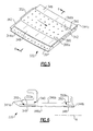
- Figure 5 illustrates another example blade outer air seal member 332 in a perspective view
- Figure 6 illustrates the blade outer air seal member 332 in cross-section.
- the blade outer air seal member 332 includes a body 340 that extends between two circumferential sides 342, axially between a leading edge 344a and a trailing edge 344b, and between a gas path side 346a and a radially outer side 346b opposite the gas path side 346a.
- the blade outer air seal member 332 includes a coating 348 that is disposed on a portion 350 of the gas path side 346a.
- part of the coating 348 is disposed on a first area 350a and another part of the coating 348 is disposed on a second area 350b.
- the areas 350a and 350b are separated by the blade rub area 352 such that the coating 348 is discontinuous on the gas path side 346a.
- the blade outer air seal member 332 includes a row 390 of cooling holes that extend adjacent the coating 348 that is located on the leading edge 344a side of the blade outer air seal member 332.
- the cooling holes can extend under the coating 348, as shown in Figure 3 .
- the row 390 is located closer to the coating 348 that is on the first area 350a than to the coating 348 that is on the second area 350b.
- another row 392 of cooling holes may be provided along the coating 348 that is on the second area 350b.
- the row 392 is unnecessary because the cooling film emitted from the row 390 flows over the surface of the coating 348 on the second area 350b.
- the coating 348 on the first area 350a is cooled by cooling holes 394 in the leading edge 344a.
- the row 390 of cooling holes is adjacent a terminal edge 396a of the coating 348 on the first area 350a.
- the other row 392 of cooling holes is adjacent a terminal edge 396b of the coating 348 on the second area 350b.
- each hole in the row 390 is an equivalent distance from the terminal edge 396a and each hole in the row 392 is an equivalent distance from the terminal edge 396b.
- the cooling holes in the blade rub area 352 help to maintain the blade rub area 352 at a desirable temperature.
- the areas 350a and 350b outside of the blade rub area 352 are thermally protected by the coating 348 and therefore do not require as much cooling as the blade rub area 352.
- the areas 350a and 350b outside of the blade rub area 352 do not include cooling holes. That is, some of the cooling that might otherwise have been used to cool the areas 350a and 350b outside of the blade rub area 352 may instead be used to cool the blade rub area 352 that does not include any coating thereon.
- the blade outer area seal member 332 embodies a method of establishing a greater amount of cooling to the bare blade rub area 352 than to the areas 350a and 350b that are coated by providing cooling holes on the blade rub area 352 but not on the coated areas 350a and 350b.
- the coatings disclosed herein do not contact the tips of the blades. There is therefore no need for the coatings to be abradable with a certain predetermined porosity. Thus, the porosity of the coatings disclosed herein may be reduced to substantially zero if desired, without regard to the abradability with the tips of the blades. Moreover, because the disclosed coatings are not in contact with the tips of the blades and see less heat, the composition of the coatings can be varied from compositions previously used. However, in a few examples, the coating is or includes a ceramic material, such as yttria stabilized zirconia, gadolinia stabilized zirconia, or combinations thereof.
Landscapes
- Engineering & Computer Science (AREA)
- Mechanical Engineering (AREA)
- General Engineering & Computer Science (AREA)
- Turbine Rotor Nozzle Sealing (AREA)
Abstract
Description
- This disclosure relates to seals and, more particularly, to a blade outer air seal member for a gas turbine engine.
- Conventional gas turbine engines are widely known and used as ground-based turbines for energy production or for propelling aircraft or other vehicles. Typically, a gas turbine engine includes a compressor section, a combustor section, and a turbine section that cooperate in the combustion of fuel to expand combustion gases over the turbine section in a known manner.
- A blade outer air seal is located radially outwards from the turbine section and functions as an outer wall for the hot gas flow through the turbine section. Due to large pressures and the contact with the hot gas flow, the blade outer air seal is made of a strong, oxidation-resistant metal alloy and requires a cooling system to keep the alloy below a certain temperature. For example, relatively cool air is taken from an air flow through the engine (e.g., compressor) and routed through an intricate system of cooling passages in the seal to maintain a desirable seal temperature. The gas path surface of the blade outer air seal may include a thermal, environmental or corrosion resistance coating system to help protect the underlying metal alloy.
- Disclosed is a blade outer air seal member that includes a body that extends between two circumferential sides, axially between a leading edge and a trailing edge, and between a gas path side and a radially outer side opposite the gas path side. A ceramic coating is initially disposed on a portion of the gas path side outside of a blade rub area of the gas path side such that the blade rub area is bare with regard to any ceramic coating.
- In another aspect, the blade outer air seal member also includes a cooling passage that has an outlet hole that opens at a bare area such as a blade rub area. The cooling passage extends in the body in an axial direction such that a portion of the cooling passage is adjacent the ceramic coating.
- Also disclosed is a method for enhancing durability of a blade outer air seal member. The method includes establishing a greater amount of cooling to the blade rub area of the gas path side than to the portion that is coated.
- The various features and advantages of the disclosed examples will become apparent to those skilled in the art from the following detailed description. The drawings that accompany the detailed description can be briefly described as follows.
-
-
Figure 1 illustrates an example turbine section. -
Figure 2 illustrates an example blade outer air seal member having a partial ceramic coating. -
Figure 3 illustrates another example blade outer air seal member having a partial ceramic coating and a cooling passage that extends under the coating. -
Figure 4 illustrates another example blade outer air seal member that has a tapered ceramic coating. -
Figure 5 illustrates an example blade outer air seal member that has a row of circumferential cooling holes. -
Figure 6 is a cross-sectional view of the blade outer air seal member ofFigure 5 . -
Figure 1 illustrates a selected portion of aturbine section 20 of a gas turbine engine. The gas turbine engine is of known arrangement and includes a compressor section, a combustion section and theturbine section 20. Theturbine section 20 includesturbine blades 22 andturbine vanes 24. - The
turbine blades 22 receive ahot gas flow 26 from the combustion section of the engine. Theturbine section 20 includes a blade outerair seal system 28 having a blade outerair seal member 32 that functions as an outer wall for thehot gas flow 26 through theturbine section 20. In the disclosed example, the blade outerair seal member 32 is removably secured to asupport 34 using L-shaped hooks or other attachment features. Thesupport 34 is secured to acase 36 that generally surrounds theturbine section 20. Theturbine section 20 is provided with a plurality of blade outerair seal members 32, or segments, that are circumferentially arranged about theturbine blades 22. The features of the blade outerair seal member 32 that will be described below with regard to the normal orientation of the blade outerair seal member 32 in the engine relative to a central axis A of the engine. -
Figure 1 is a schematic presentation to illustrate an example operating environment of the blade outerair seal member 32 and is not a limitation on the disclosed examples. Additionally, there are various types of gas turbine engines, many of which could benefit from the examples disclosed herein. -
Figure 2 illustrates an example of the blade outerair seal member 32. In the illustration, the blade outerair seal member 32 is shown in a simplified view, without connection features or cooling passages that may be included. In this example, the blade outerair seal member 32 includes abody 40 that extends between two circumferential sides 42 (one shown), axially between aleading edge 44a and a trailingedge 44b, between agas path side 46a and a radiallyouter side 46b opposite thegas path side 46a. - A
coating 48 is initially disposed on aportion 50 of thegas path side 46a. Theportion 50 is outside of a blade rub area 52 (i.e., surface) of thegas path side 46a. Theblade rub area 52 is initially bare with regard to any of thecoating 48. Theblade rub area 52 optionally includes another type of types of non-ceramic or non-thermal barrier coatings (e.g., MCrAlY), but does not include a ceramic coating. That is, theblade rub area 52 is bare with, regard to any ceramic coating, prior to any contact with the tips of theblades 22 and is not bare from abrasion contact with theblades 22. For example, theblade rub area 52 is directly outboard of the tips of theblades 22 and rubs against the tips during a wear-in period of the blade outerair seal member 32. After the wear-in period, there is reduced or no contact between the tips and theblade rub area 52. - In the illustrated example, the coated
portion 50 of thegas path side 46a includes a first area (to the left of theblade rub area 52 in the illustration) that extends along theleading edge 44a and a second area (to the right of theblade rub area 52 in the illustration) that extends along the trailingedge 44b. Theblade rub area 52 separates the first area from the second area, although in other examples theportion 50 need not be divided. In a further example, theblade rub area 52 bisects the coatedportion 50 such that the size of the first area is approximately equivalent to the size of the second area. It is to be understood that in other examples, the sizes of the first area and the second area need not be equal and the sizes may depend upon the particular design of theturbine section 20. -
Figure 3 illustrates another example blade outerair seal member 132. In this disclosure, like reference numerals designate like elements where appropriate and reference numerals with the addition of one-hundred or multiples thereof designate modified elements. The modified elements are understood to incorporate the same features and benefits of the corresponding elements. In this example, the blade outerair seal member 132 is similar to the blade outerair seal member 32 shown inFigure 2 , but additionally includes acooling passage 60 that extends within thebody 40. The blade outerair seal member 132 may include multiple ofsuch cooling passages 60. Thecooling passage 60 has anoutlet hole 62 that opens at theblade rub area 52. Thecooling passage 60 extends in thebody 40 in an axial direction relative to engine axis A such that aportion 64 of thecooling passage 60 is adjacent to thecoating 48. In a further example, theportion 64 of thecooling passage 60 is axially aligned (i.e., at the same axial position), as represented at 66, with a part of thecoating 48. That is, thecooling passage 60 in this example extends forward from theoutlet hole 62 toward theleading edge 44a and underneath a portion of thecoating 48. In this example, thecooling passage 60 has aninlet hole 68 on the radiallyouter side 46b of the blade outerair seal member 132. - In operation, the tips of the
blades 22 extend into contact with theblade rub area 52 of thebody 40. During the wear-in period, the tips rub against theblade rub area 52, or at least a portion thereof. After the wear-in period, theblade rub area 52 is exposed to high temperature combustion gases. - In use, the cooling fluid flowing through the
cooling passage 60 enters throughinlet hole 68 and travels through theportion 64 to theoutlet hole 62. The cooling fluid that exits theoutlet hole 62 provides a film of cooling fluid over theblade rub area 52 to help maintain theblade rub area 52 at a desired temperature. The routing of thecooling passage 60 under and adjacent thecoating 48 also helps to maintain thecoated portions 50 in the first area at a desirable temperature. Thus, thecooling passage 60 serves the dual purpose of helping to cool the coated areas as well as film cooling theblade rub area 52. The disclosedcooling passage 60 may therefore reduce the need for other cooling to thecoated portions 50. For example, thecoated portions 50 may be cooled through the use of film cooling holes that are located on theleading edge 44a (not shown). - With cycling of the engine between on and off conditions, or even between throttle levels, different amounts of heat are generated. The repeated heating and relative cooling of the
blade rub area 52 causes thebody 40 at theblade rub area 52 to thermally expand and contract. Thecooling passage 60 is provided to maintain theblade rub area 52 at a desired temperature to reduce the effects of thermal expansion and contraction. - In comparison, a blade outer air seal member having a gas path side that is entirely coated with a ceramic thermal barrier coating is subject to wear against the tips of the blades during a wear-in period. The tips wear or spall away the ceramic coating in the blade rub area. With continued use, the ceramic coating can spall and expose the underlying bare metal to the high temperature combustion gases. With local exposure of the central portion of the BOAS, excessive temperatures and stresses can lead to early degradation of the segment. In areas outside of the blade rub area, less heat is generated. The difference in heat generation between the blade rub area and areas outside of the blade rub area cause thermal stress in the axial direction of the blade outer air seal member. The thermal stresses can cause cracking in the coating and/or in the underlying metal of the body. However, in the disclosed example where sufficient cooling is provided to the
blade rub area 52 to account for there not being any of thecoating 48, the heat from the high temperature combustion gases can be adequately removed to limit the effects of thermal expansion and contraction. -
Figure 4 illustrates another embodiment blade outerair seal member 232. In this example, the blade outerair seal member 232 is similar to the blade outerair seal member 32 shown inFigure 2 , in which thecoating 48 has a uniform thickness throughout. However, in this example, the blade outerair seal member 232 includes acoating 248 that tapers axially. As shown, thecoating 248 is thicker at a first location 280 than at a second location 282 that is closer to anaxial center 284 of the blade outerair seal member 232. For instance, thecoating 248 is thickest at theleading edge 44a, the trailingedge 44b, or both and reduces in thickness as a function of distance from theaxial center 284. - In the illustrated example, the
coating 248 on the first area (to the left of theblade rub area 52 in the illustration) of thegas path side 46a tapers from theleading edge 44a to a zero thickness at a terminal edge of the coating along theblade rub area 52. Likewise, thecoating 248 on the second area (to the right of theblade rub area 52 in the illustration) of thegas path side 46a tapers in thickness from the trailingedge 44b toward a zero thickness at a terminal edge of thecoating 248 along theblade rub area 52. In a further example, thecoating 284 tapers only over a partial axial length of the first area and/or the second area. - In operation, the tapered thickness of the
coating 248 helps to reduce thermal mechanical fatigue of thecoating 248 due to heat cycling and difference in temperature between theblade rub area 52 and the portions outside of theblade rub area 52 on which thecoating 248 is disposed. That is, there is less of thecoating 248 material near theblade rub area 52, which is the hottest portion of the blade outerair seal member 232. -
Figure 5 illustrates another example blade outerair seal member 332 in a perspective view andFigure 6 illustrates the blade outerair seal member 332 in cross-section. In this example, the blade outerair seal member 332 includes abody 340 that extends between twocircumferential sides 342, axially between aleading edge 344a and a trailingedge 344b, and between agas path side 346a and a radiallyouter side 346b opposite thegas path side 346a. - The blade outer
air seal member 332 includes acoating 348 that is disposed on aportion 350 of thegas path side 346a. In this example, part of thecoating 348 is disposed on afirst area 350a and another part of thecoating 348 is disposed on asecond area 350b. Theareas blade rub area 352 such that thecoating 348 is discontinuous on thegas path side 346a. - The blade outer
air seal member 332 includes arow 390 of cooling holes that extend adjacent thecoating 348 that is located on theleading edge 344a side of the blade outerair seal member 332. The cooling holes can extend under thecoating 348, as shown inFigure 3 . As shown, therow 390 is located closer to thecoating 348 that is on thefirst area 350a than to thecoating 348 that is on thesecond area 350b. Optionally, anotherrow 392 of cooling holes may be provided along thecoating 348 that is on thesecond area 350b. However, in some examples, therow 392 is unnecessary because the cooling film emitted from therow 390 flows over the surface of thecoating 348 on thesecond area 350b. Thecoating 348 on thefirst area 350a is cooled by coolingholes 394 in theleading edge 344a. - In the illustrated example, the
row 390 of cooling holes is adjacent aterminal edge 396a of thecoating 348 on thefirst area 350a. Theother row 392 of cooling holes is adjacent aterminal edge 396b of thecoating 348 on thesecond area 350b. For instance, each hole in therow 390 is an equivalent distance from theterminal edge 396a and each hole in therow 392 is an equivalent distance from theterminal edge 396b. - The cooling holes in the
blade rub area 352 help to maintain theblade rub area 352 at a desirable temperature. Theareas blade rub area 352 are thermally protected by thecoating 348 and therefore do not require as much cooling as theblade rub area 352. In that regard, theareas blade rub area 352 do not include cooling holes. That is, some of the cooling that might otherwise have been used to cool theareas blade rub area 352 may instead be used to cool theblade rub area 352 that does not include any coating thereon. Thus, the blade outerarea seal member 332 embodies a method of establishing a greater amount of cooling to the bareblade rub area 352 than to theareas blade rub area 352 but not on thecoated areas - Whereas coatings that are normally used on gas path side surfaces of blade outer air seals must be abradable by having a certain porosity to allow the coating to wear away upon contact with the tips of the blades, the coatings disclosed herein do not contact the tips of the blades. There is therefore no need for the coatings to be abradable with a certain predetermined porosity. Thus, the porosity of the coatings disclosed herein may be reduced to substantially zero if desired, without regard to the abradability with the tips of the blades. Moreover, because the disclosed coatings are not in contact with the tips of the blades and see less heat, the composition of the coatings can be varied from compositions previously used. However, in a few examples, the coating is or includes a ceramic material, such as yttria stabilized zirconia, gadolinia stabilized zirconia, or combinations thereof.
- Although a combination of features is shown in the illustrated examples, not all of them need to be combined to realize the benefits of various embodiments of this disclosure. In other words, a system designed according to an embodiment of this disclosure will not necessarily include all of the features shown in any one of the Figures or all of the portions schematically shown in the Figures. Moreover, selected features of one example embodiment may be combined with selected features of other example embodiments.
- The preceding description is exemplary rather than limiting in nature. Variations and modifications to the disclosed examples may become apparent to those skilled in the art that do not necessarily depart from the essence of this disclosure. The scope of legal protection given to this disclosure can only be determined by studying the following claims.
Claims (15)
- A blade outer air seal member (32; 132;232;332) comprising:a body (40;340) that extends between two circumferential sides (42;342), axially between a leading edge (44a;344a) and a trailing edge (44b;344b), and between a gas path side (46a;346a) and a radially outer side (46b;346b) opposite the gas path side (46a;346a); anda ceramic coating (48;248;348) initially disposed on a portion (50;350) of the gas path side (46a;346a) outside of a blade rub area (52;352) of the gas path side (46a;346a) such that the blade rub area (52;352) is bare with regard to any of the ceramic coating (48;248;348).
- The blade outer air seal member (32;132;232;332) as recited in claim 1, wherein the coated portion (50;350) includes a first area along the leading edge (44a;344a) and a second area along the trailing edge (44b;344b).
- The blade outer air seal member (32;132;232;332) as recited in claim 2, wherein the blade rub area (52;352) separates the first area and the second area.
- The blade outer air seal member (32;132;232;332) as recited in claim 2 or 3, wherein the blade rub area (52;352) includes a circumferential row of cooling holes that are located closer to the first area than to the second area.
- The blade outer air seal member (32;132;232;332) as recited in any of claims 1 to 3, wherein the blade rub area (52;352) includes cooling holes.
- The blade outer air seal member (32;132;232;332) as recited in claim 5, wherein the coated portion (50;350) is free of any cooling holes.
- The blade outer air seal member (232) as recited in any preceding claim, wherein the coating thickness tapers axially, and optionally the ceramic coating (248) is thicker at a first location (280) than at a second location (282) that is closer to the axial center (284) of the body (40).
- The blade outer air seal member (32;132;332) as recited in any of claims 1 to 6, wherein the ceramic coating (48;348) has a uniform thickness throughout.
- The blade outer air seal member (332) as recited in any preceding claim, wherein the blade rub area (352) includes a first circumferential row (390) of cooling holes adjacent to a first terminal edge (396a) of the coating (348) and a second circumferential row (392) of cooling holes adjacent to a second, different terminal edge of the ceramic coating.
- The blade outer air seal member (132) as recited in any preceding claim, wherein the body (40) includes a cooling passage (60) having an outlet hole (62) that opens at the bare area (52) and the cooling passage (60) extends in the body (40) in an axial direction such that a portion (64) of the cooling passage (60) is adjacent the ceramic coating (48).
- A blade outer air seal member (132) comprising:a body (40) that extends between two circumferential sides (42), axially between a leading edge (44a) and a trailing edge (44b), and between a gas path side (46a) and a radially outer side (46b) opposite the gas path side (46a);a ceramic coating (48) initially disposed on a portion (50) of the gas path side (46a) such that an area (52) of the gas path side (46a) is bare with regard to any of the ceramic coating (48); anda cooling passage (60) having an outlet hole (62) that opens at the bare area (52), the cooling passage (60) extending in the body (40) in an axial direction such that a portion (64) of the cooling passage (60) is adjacent the ceramic coating (48).
- The blade outer air seal member (132) as recited in claim 11, wherein the coated portion (50) includes a first area along the leading edge (44a) and a second area along the trailing edge (44b), and optionally the bare area (52) separates the first area and the second area.
- The blade outer air seal member (132) as recited in claim 10, 11 or 12, wherein the cooling passage (60) extends from the outlet hole (62) axially forward in the body (40) toward the leading edge (44a).
- The blade outer air seal member (132) as recited in any of claims 10 to 13, wherein a portion (64) of the cooling passage (60) is axially aligned with the coated portion.
- A method for enhancing durability of a blade outer air seal member (32;132;232;332), the method comprising:providing a blade outer air seal member (32;132;232;332) that includes a body (40;340) that extends between two circumferential sides (42;342), axially between a leading edge (44a;344a) and a trailing edge (44b;344b), and between a gas path side (46a;346a) and a radially outer side (46b;346b) opposite the gas path side (46a;346a), and a ceramic coating (48;248;348) on a portion (50;350) of the gas path side (46a;346a) outside of a blade rub area (52;352)of the gas path side (46a;346a) such that the blade rub area (52;352) is bare with regard to any of the ceramic coating (48;248;348); andestablishing a greater amount of cooling to the blade rub area (52;352) of the gas path side (46a;346a) than to the portion (50;350) that is coated, optionally by providing cooling holes (62;390;392) on the blade rub area (52;352) but not on the portions (50;350) that are coated.
Applications Claiming Priority (1)
| Application Number | Priority Date | Filing Date | Title |
|---|---|---|---|
| US13/183,891 US9062558B2 (en) | 2011-07-15 | 2011-07-15 | Blade outer air seal having partial coating |
Publications (3)
| Publication Number | Publication Date |
|---|---|
| EP2546463A2 true EP2546463A2 (en) | 2013-01-16 |
| EP2546463A3 EP2546463A3 (en) | 2014-08-13 |
| EP2546463B1 EP2546463B1 (en) | 2015-10-07 |
Family
ID=46545628
Family Applications (1)
| Application Number | Title | Priority Date | Filing Date |
|---|---|---|---|
| EP12175296.8A Active EP2546463B1 (en) | 2011-07-15 | 2012-07-06 | Blade outer air seal having partial coating and method for enhancing its durability |
Country Status (2)
| Country | Link |
|---|---|
| US (1) | US9062558B2 (en) |
| EP (1) | EP2546463B1 (en) |
Cited By (2)
| Publication number | Priority date | Publication date | Assignee | Title |
|---|---|---|---|---|
| EP3103967A1 (en) * | 2015-06-10 | 2016-12-14 | United Technologies Corporation | Blade outer air seal having partial coating |
| US9995165B2 (en) | 2011-07-15 | 2018-06-12 | United Technologies Corporation | Blade outer air seal having partial coating |
Families Citing this family (8)
| Publication number | Priority date | Publication date | Assignee | Title |
|---|---|---|---|---|
| DE102011053619A1 (en) * | 2011-09-14 | 2013-03-14 | Becker Marine Systems Gmbh & Co. Kg | Propeller nozzle for watercraft |
| US9833869B2 (en) | 2013-02-11 | 2017-12-05 | United Technologies Corporation | Blade outer air seal surface |
| EP2961930B1 (en) * | 2013-02-26 | 2020-05-27 | United Technologies Corporation | Edge treatment for blade outer air seal segment |
| WO2014171997A2 (en) * | 2013-02-28 | 2014-10-23 | United Technologies Corporation | Contoured blade outer air seal for a gas turbine engine |
| WO2014186015A2 (en) * | 2013-03-11 | 2014-11-20 | United Technologies Corporation | Actuator for gas turbine engine blade outer air seal |
| US10502093B2 (en) * | 2017-12-13 | 2019-12-10 | Pratt & Whitney Canada Corp. | Turbine shroud cooling |
| US11047250B2 (en) * | 2019-04-05 | 2021-06-29 | Raytheon Technologies Corporation | CMC BOAS transverse hook arrangement |
| CN114320488A (en) * | 2021-10-20 | 2022-04-12 | 中国航发四川燃气涡轮研究院 | Sealing structure of aeroengine turbine guider blade flange plate |
Family Cites Families (21)
| Publication number | Priority date | Publication date | Assignee | Title |
|---|---|---|---|---|
| US4337016A (en) * | 1979-12-13 | 1982-06-29 | United Technologies Corporation | Dual wall seal means |
| US4551064A (en) * | 1982-03-05 | 1985-11-05 | Rolls-Royce Limited | Turbine shroud and turbine shroud assembly |
| GB2125111B (en) * | 1982-03-23 | 1985-06-05 | Rolls Royce | Shroud assembly for a gas turbine engine |
| US4422648A (en) * | 1982-06-17 | 1983-12-27 | United Technologies Corporation | Ceramic faced outer air seal for gas turbine engines |
| US5282718A (en) * | 1991-01-30 | 1994-02-01 | United Technologies Corporation | Case treatment for compressor blades |
| DE69204861T2 (en) * | 1991-01-30 | 1996-05-23 | United Technologies Corp | Fan housing with recirculation channels. |
| US5165847A (en) * | 1991-05-20 | 1992-11-24 | General Electric Company | Tapered enlargement metering inlet channel for a shroud cooling assembly of gas turbine engines |
| US5439348A (en) | 1994-03-30 | 1995-08-08 | United Technologies Corporation | Turbine shroud segment including a coating layer having varying thickness |
| DE19619438B4 (en) | 1996-05-14 | 2005-04-21 | Alstom | Heat release segment for a turbomachine |
| DE59809578D1 (en) * | 1998-10-05 | 2003-10-16 | Alstom Switzerland Ltd | Fluid machine for compressing or relaxing a compressible medium |
| US6196792B1 (en) | 1999-01-29 | 2001-03-06 | General Electric Company | Preferentially cooled turbine shroud |
| US6670046B1 (en) | 2000-08-31 | 2003-12-30 | Siemens Westinghouse Power Corporation | Thermal barrier coating system for turbine components |
| US6726448B2 (en) * | 2002-05-15 | 2004-04-27 | General Electric Company | Ceramic turbine shroud |
| US6887529B2 (en) | 2003-04-02 | 2005-05-03 | General Electric Company | Method of applying environmental and bond coatings to turbine flowpath parts |
| US6905302B2 (en) * | 2003-09-17 | 2005-06-14 | General Electric Company | Network cooled coated wall |
| US7008183B2 (en) * | 2003-12-26 | 2006-03-07 | General Electric Company | Deflector embedded impingement baffle |
| US7306424B2 (en) | 2004-12-29 | 2007-12-11 | United Technologies Corporation | Blade outer seal with micro axial flow cooling system |
| US7726936B2 (en) * | 2006-07-25 | 2010-06-01 | Siemens Energy, Inc. | Turbine engine ring seal |
| US8439629B2 (en) | 2007-03-01 | 2013-05-14 | United Technologies Corporation | Blade outer air seal |
| US8100640B2 (en) | 2007-10-25 | 2012-01-24 | United Technologies Corporation | Blade outer air seal with improved thermomechanical fatigue life |
| US8177492B2 (en) | 2008-03-04 | 2012-05-15 | United Technologies Corporation | Passage obstruction for improved inlet coolant filling |
-
2011
- 2011-07-15 US US13/183,891 patent/US9062558B2/en active Active
-
2012
- 2012-07-06 EP EP12175296.8A patent/EP2546463B1/en active Active
Non-Patent Citations (1)
| Title |
|---|
| None |
Cited By (2)
| Publication number | Priority date | Publication date | Assignee | Title |
|---|---|---|---|---|
| US9995165B2 (en) | 2011-07-15 | 2018-06-12 | United Technologies Corporation | Blade outer air seal having partial coating |
| EP3103967A1 (en) * | 2015-06-10 | 2016-12-14 | United Technologies Corporation | Blade outer air seal having partial coating |
Also Published As
| Publication number | Publication date |
|---|---|
| US20130017058A1 (en) | 2013-01-17 |
| EP2546463A3 (en) | 2014-08-13 |
| US9062558B2 (en) | 2015-06-23 |
| EP2546463B1 (en) | 2015-10-07 |
Similar Documents
| Publication | Publication Date | Title |
|---|---|---|
| EP2546463B1 (en) | Blade outer air seal having partial coating and method for enhancing its durability | |
| US8328505B2 (en) | Turbine shroud thermal distortion control | |
| US9995165B2 (en) | Blade outer air seal having partial coating | |
| US8215900B2 (en) | Turbine vane with high temperature capable skins | |
| EP1079071B1 (en) | Turbine blade with preferentially cooled trailing edge pressure wall | |
| EP2540994B1 (en) | Chordal mounting arrangement for low-ductility turbine shroud | |
| US20170218768A1 (en) | Blade of a turbomachine having blade root thermal insulation | |
| US11555419B2 (en) | Cost effective manufacturing method for GSAC incorporating a stamped preform | |
| CN104704203A (en) | Turbine vane arrangement | |
| US20210054745A1 (en) | Turbine vane assembly with ceramic matrix composite parts and platform sealing features | |
| US11492692B2 (en) | Thermal barrier coating with high corrosion resistance | |
| US9068469B2 (en) | Gas turbine engines with abradable turbine seal assemblies | |
| EP3196419A1 (en) | Blade outer air seal having surface layer with pockets | |
| US20170268368A1 (en) | Boas spring loaded rail shield | |
| US20100247291A1 (en) | Gas turbine engine article having columnar microstructure | |
| EP2574545A2 (en) | Wear Resistant Coating and Use Thereof | |
| EP3103967B1 (en) | Blade outer air seal having partial coating | |
| EP3192972B1 (en) | Flow exchange baffle insert for a gas turbine engine component | |
| US20150275682A1 (en) | Sprayed haynes 230 layer to increase spallation life of thermal barrier coating on a gas turbine engine component | |
| WO2016148695A1 (en) | Turbine airfoil with internal cooling system having nearwall cooling channels formed from an inner wall formed separately from an outer wall forming the turbine airfoil |
Legal Events
| Date | Code | Title | Description |
|---|---|---|---|
| PUAI | Public reference made under article 153(3) epc to a published international application that has entered the european phase |
Free format text: ORIGINAL CODE: 0009012 |
|
| AK | Designated contracting states |
Kind code of ref document: A2 Designated state(s): AL AT BE BG CH CY CZ DE DK EE ES FI FR GB GR HR HU IE IS IT LI LT LU LV MC MK MT NL NO PL PT RO RS SE SI SK SM TR |
|
| AX | Request for extension of the european patent |
Extension state: BA ME |
|
| PUAL | Search report despatched |
Free format text: ORIGINAL CODE: 0009013 |
|
| AK | Designated contracting states |
Kind code of ref document: A3 Designated state(s): AL AT BE BG CH CY CZ DE DK EE ES FI FR GB GR HR HU IE IS IT LI LT LU LV MC MK MT NL NO PL PT RO RS SE SI SK SM TR |
|
| AX | Request for extension of the european patent |
Extension state: BA ME |
|
| RIC1 | Information provided on ipc code assigned before grant |
Ipc: F01D 11/08 20060101ALI20140710BHEP Ipc: F01D 5/20 20060101AFI20140710BHEP |
|
| 17P | Request for examination filed |
Effective date: 20150213 |
|
| RBV | Designated contracting states (corrected) |
Designated state(s): AL AT BE BG CH CY CZ DE DK EE ES FI FR GB GR HR HU IE IS IT LI LT LU LV MC MK MT NL NO PL PT RO RS SE SI SK SM TR |
|
| GRAP | Despatch of communication of intention to grant a patent |
Free format text: ORIGINAL CODE: EPIDOSNIGR1 |
|
| INTG | Intention to grant announced |
Effective date: 20150417 |
|
| GRAS | Grant fee paid |
Free format text: ORIGINAL CODE: EPIDOSNIGR3 |
|
| GRAA | (expected) grant |
Free format text: ORIGINAL CODE: 0009210 |
|
| AK | Designated contracting states |
Kind code of ref document: B1 Designated state(s): AL AT BE BG CH CY CZ DE DK EE ES FI FR GB GR HR HU IE IS IT LI LT LU LV MC MK MT NL NO PL PT RO RS SE SI SK SM TR |
|
| REG | Reference to a national code |
Ref country code: GB Ref legal event code: FG4D |
|
| REG | Reference to a national code |
Ref country code: AT Ref legal event code: REF Ref document number: 753891 Country of ref document: AT Kind code of ref document: T Effective date: 20151015 Ref country code: CH Ref legal event code: EP |
|
| REG | Reference to a national code |
Ref country code: IE Ref legal event code: FG4D |
|
| REG | Reference to a national code |
Ref country code: DE Ref legal event code: R096 Ref document number: 602012011274 Country of ref document: DE |
|
| REG | Reference to a national code |
Ref country code: NL Ref legal event code: MP Effective date: 20151007 |
|
| REG | Reference to a national code |
Ref country code: AT Ref legal event code: MK05 Ref document number: 753891 Country of ref document: AT Kind code of ref document: T Effective date: 20151007 |
|
| REG | Reference to a national code |
Ref country code: LT Ref legal event code: MG4D |
|
| PG25 | Lapsed in a contracting state [announced via postgrant information from national office to epo] |
Ref country code: IT Free format text: LAPSE BECAUSE OF FAILURE TO SUBMIT A TRANSLATION OF THE DESCRIPTION OR TO PAY THE FEE WITHIN THE PRESCRIBED TIME-LIMIT Effective date: 20151007 Ref country code: LT Free format text: LAPSE BECAUSE OF FAILURE TO SUBMIT A TRANSLATION OF THE DESCRIPTION OR TO PAY THE FEE WITHIN THE PRESCRIBED TIME-LIMIT Effective date: 20151007 Ref country code: HR Free format text: LAPSE BECAUSE OF FAILURE TO SUBMIT A TRANSLATION OF THE DESCRIPTION OR TO PAY THE FEE WITHIN THE PRESCRIBED TIME-LIMIT Effective date: 20151007 Ref country code: NL Free format text: LAPSE BECAUSE OF FAILURE TO SUBMIT A TRANSLATION OF THE DESCRIPTION OR TO PAY THE FEE WITHIN THE PRESCRIBED TIME-LIMIT Effective date: 20151007 Ref country code: NO Free format text: LAPSE BECAUSE OF FAILURE TO SUBMIT A TRANSLATION OF THE DESCRIPTION OR TO PAY THE FEE WITHIN THE PRESCRIBED TIME-LIMIT Effective date: 20160107 Ref country code: IS Free format text: LAPSE BECAUSE OF FAILURE TO SUBMIT A TRANSLATION OF THE DESCRIPTION OR TO PAY THE FEE WITHIN THE PRESCRIBED TIME-LIMIT Effective date: 20160207 Ref country code: ES Free format text: LAPSE BECAUSE OF FAILURE TO SUBMIT A TRANSLATION OF THE DESCRIPTION OR TO PAY THE FEE WITHIN THE PRESCRIBED TIME-LIMIT Effective date: 20151007 |
|
| PG25 | Lapsed in a contracting state [announced via postgrant information from national office to epo] |
Ref country code: GR Free format text: LAPSE BECAUSE OF FAILURE TO SUBMIT A TRANSLATION OF THE DESCRIPTION OR TO PAY THE FEE WITHIN THE PRESCRIBED TIME-LIMIT Effective date: 20160108 Ref country code: AT Free format text: LAPSE BECAUSE OF FAILURE TO SUBMIT A TRANSLATION OF THE DESCRIPTION OR TO PAY THE FEE WITHIN THE PRESCRIBED TIME-LIMIT Effective date: 20151007 Ref country code: FI Free format text: LAPSE BECAUSE OF FAILURE TO SUBMIT A TRANSLATION OF THE DESCRIPTION OR TO PAY THE FEE WITHIN THE PRESCRIBED TIME-LIMIT Effective date: 20151007 Ref country code: SE Free format text: LAPSE BECAUSE OF FAILURE TO SUBMIT A TRANSLATION OF THE DESCRIPTION OR TO PAY THE FEE WITHIN THE PRESCRIBED TIME-LIMIT Effective date: 20151007 Ref country code: RS Free format text: LAPSE BECAUSE OF FAILURE TO SUBMIT A TRANSLATION OF THE DESCRIPTION OR TO PAY THE FEE WITHIN THE PRESCRIBED TIME-LIMIT Effective date: 20151007 Ref country code: LV Free format text: LAPSE BECAUSE OF FAILURE TO SUBMIT A TRANSLATION OF THE DESCRIPTION OR TO PAY THE FEE WITHIN THE PRESCRIBED TIME-LIMIT Effective date: 20151007 Ref country code: PT Free format text: LAPSE BECAUSE OF FAILURE TO SUBMIT A TRANSLATION OF THE DESCRIPTION OR TO PAY THE FEE WITHIN THE PRESCRIBED TIME-LIMIT Effective date: 20160208 Ref country code: PL Free format text: LAPSE BECAUSE OF FAILURE TO SUBMIT A TRANSLATION OF THE DESCRIPTION OR TO PAY THE FEE WITHIN THE PRESCRIBED TIME-LIMIT Effective date: 20151007 |
|
| REG | Reference to a national code |
Ref country code: DE Ref legal event code: R097 Ref document number: 602012011274 Country of ref document: DE |
|
| PG25 | Lapsed in a contracting state [announced via postgrant information from national office to epo] |
Ref country code: CZ Free format text: LAPSE BECAUSE OF FAILURE TO SUBMIT A TRANSLATION OF THE DESCRIPTION OR TO PAY THE FEE WITHIN THE PRESCRIBED TIME-LIMIT Effective date: 20151007 |
|
| PLBE | No opposition filed within time limit |
Free format text: ORIGINAL CODE: 0009261 |
|
| STAA | Information on the status of an ep patent application or granted ep patent |
Free format text: STATUS: NO OPPOSITION FILED WITHIN TIME LIMIT |
|
| PG25 | Lapsed in a contracting state [announced via postgrant information from national office to epo] |
Ref country code: DK Free format text: LAPSE BECAUSE OF FAILURE TO SUBMIT A TRANSLATION OF THE DESCRIPTION OR TO PAY THE FEE WITHIN THE PRESCRIBED TIME-LIMIT Effective date: 20151007 Ref country code: SM Free format text: LAPSE BECAUSE OF FAILURE TO SUBMIT A TRANSLATION OF THE DESCRIPTION OR TO PAY THE FEE WITHIN THE PRESCRIBED TIME-LIMIT Effective date: 20151007 Ref country code: EE Free format text: LAPSE BECAUSE OF FAILURE TO SUBMIT A TRANSLATION OF THE DESCRIPTION OR TO PAY THE FEE WITHIN THE PRESCRIBED TIME-LIMIT Effective date: 20151007 Ref country code: SK Free format text: LAPSE BECAUSE OF FAILURE TO SUBMIT A TRANSLATION OF THE DESCRIPTION OR TO PAY THE FEE WITHIN THE PRESCRIBED TIME-LIMIT Effective date: 20151007 Ref country code: RO Free format text: LAPSE BECAUSE OF FAILURE TO SUBMIT A TRANSLATION OF THE DESCRIPTION OR TO PAY THE FEE WITHIN THE PRESCRIBED TIME-LIMIT Effective date: 20151007 |
|
| 26N | No opposition filed |
Effective date: 20160708 |
|
| PG25 | Lapsed in a contracting state [announced via postgrant information from national office to epo] |
Ref country code: SI Free format text: LAPSE BECAUSE OF FAILURE TO SUBMIT A TRANSLATION OF THE DESCRIPTION OR TO PAY THE FEE WITHIN THE PRESCRIBED TIME-LIMIT Effective date: 20151007 |
|
| PG25 | Lapsed in a contracting state [announced via postgrant information from national office to epo] |
Ref country code: BE Free format text: LAPSE BECAUSE OF FAILURE TO SUBMIT A TRANSLATION OF THE DESCRIPTION OR TO PAY THE FEE WITHIN THE PRESCRIBED TIME-LIMIT Effective date: 20151007 |
|
| REG | Reference to a national code |
Ref country code: CH Ref legal event code: PL |
|
| PG25 | Lapsed in a contracting state [announced via postgrant information from national office to epo] |
Ref country code: MC Free format text: LAPSE BECAUSE OF FAILURE TO SUBMIT A TRANSLATION OF THE DESCRIPTION OR TO PAY THE FEE WITHIN THE PRESCRIBED TIME-LIMIT Effective date: 20151007 |
|
| PG25 | Lapsed in a contracting state [announced via postgrant information from national office to epo] |
Ref country code: FR Free format text: LAPSE BECAUSE OF NON-PAYMENT OF DUE FEES Effective date: 20160801 Ref country code: LI Free format text: LAPSE BECAUSE OF NON-PAYMENT OF DUE FEES Effective date: 20160731 Ref country code: CH Free format text: LAPSE BECAUSE OF NON-PAYMENT OF DUE FEES Effective date: 20160731 |
|
| REG | Reference to a national code |
Ref country code: FR Ref legal event code: ST Effective date: 20170331 |
|
| REG | Reference to a national code |
Ref country code: IE Ref legal event code: MM4A |
|
| REG | Reference to a national code |
Ref country code: DE Ref legal event code: R082 Ref document number: 602012011274 Country of ref document: DE Representative=s name: SCHMITT-NILSON SCHRAUD WAIBEL WOHLFROM PATENTA, DE |
|
| REG | Reference to a national code |
Ref country code: DE Ref legal event code: R082 Ref document number: 602012011274 Country of ref document: DE Representative=s name: SCHMITT-NILSON SCHRAUD WAIBEL WOHLFROM PATENTA, DE Ref country code: DE Ref legal event code: R081 Ref document number: 602012011274 Country of ref document: DE Owner name: UNITED TECHNOLOGIES CORP. (N.D.GES.D. STAATES , US Free format text: FORMER OWNER: UNITED TECHNOLOGIES CORP., HARTFORD, CONN., US |
|
| PG25 | Lapsed in a contracting state [announced via postgrant information from national office to epo] |
Ref country code: IE Free format text: LAPSE BECAUSE OF NON-PAYMENT OF DUE FEES Effective date: 20160706 |
|
| PG25 | Lapsed in a contracting state [announced via postgrant information from national office to epo] |
Ref country code: LU Free format text: LAPSE BECAUSE OF NON-PAYMENT OF DUE FEES Effective date: 20160706 |
|
| PG25 | Lapsed in a contracting state [announced via postgrant information from national office to epo] |
Ref country code: CY Free format text: LAPSE BECAUSE OF FAILURE TO SUBMIT A TRANSLATION OF THE DESCRIPTION OR TO PAY THE FEE WITHIN THE PRESCRIBED TIME-LIMIT Effective date: 20151007 Ref country code: HU Free format text: LAPSE BECAUSE OF FAILURE TO SUBMIT A TRANSLATION OF THE DESCRIPTION OR TO PAY THE FEE WITHIN THE PRESCRIBED TIME-LIMIT; INVALID AB INITIO Effective date: 20120706 |
|
| PG25 | Lapsed in a contracting state [announced via postgrant information from national office to epo] |
Ref country code: MK Free format text: LAPSE BECAUSE OF FAILURE TO SUBMIT A TRANSLATION OF THE DESCRIPTION OR TO PAY THE FEE WITHIN THE PRESCRIBED TIME-LIMIT Effective date: 20151007 Ref country code: TR Free format text: LAPSE BECAUSE OF FAILURE TO SUBMIT A TRANSLATION OF THE DESCRIPTION OR TO PAY THE FEE WITHIN THE PRESCRIBED TIME-LIMIT Effective date: 20151007 Ref country code: MT Free format text: LAPSE BECAUSE OF NON-PAYMENT OF DUE FEES Effective date: 20160731 |
|
| PG25 | Lapsed in a contracting state [announced via postgrant information from national office to epo] |
Ref country code: BG Free format text: LAPSE BECAUSE OF FAILURE TO SUBMIT A TRANSLATION OF THE DESCRIPTION OR TO PAY THE FEE WITHIN THE PRESCRIBED TIME-LIMIT Effective date: 20151007 |
|
| PG25 | Lapsed in a contracting state [announced via postgrant information from national office to epo] |
Ref country code: AL Free format text: LAPSE BECAUSE OF FAILURE TO SUBMIT A TRANSLATION OF THE DESCRIPTION OR TO PAY THE FEE WITHIN THE PRESCRIBED TIME-LIMIT Effective date: 20151007 |
|
| REG | Reference to a national code |
Ref country code: DE Ref legal event code: R081 Ref document number: 602012011274 Country of ref document: DE Owner name: RAYTHEON TECHNOLOGIES CORPORATION (N.D.GES.D.S, US Free format text: FORMER OWNER: UNITED TECHNOLOGIES CORP. (N.D.GES.D. STAATES DELAWARE), FARMINGTON, CONN., US Ref country code: DE Ref legal event code: R081 Ref document number: 602012011274 Country of ref document: DE Owner name: RTX CORPORATION (N.D.GES.D. STAATES DELAWARE),, US Free format text: FORMER OWNER: UNITED TECHNOLOGIES CORP. (N.D.GES.D. STAATES DELAWARE), FARMINGTON, CONN., US |
|
| P01 | Opt-out of the competence of the unified patent court (upc) registered |
Effective date: 20230520 |
|
| PGFP | Annual fee paid to national office [announced via postgrant information from national office to epo] |
Ref country code: GB Payment date: 20250619 Year of fee payment: 14 |
|
| PGFP | Annual fee paid to national office [announced via postgrant information from national office to epo] |
Ref country code: DE Payment date: 20250620 Year of fee payment: 14 |
|
| REG | Reference to a national code |
Ref country code: DE Ref legal event code: R081 Ref document number: 602012011274 Country of ref document: DE Owner name: RTX CORPORATION (N.D.GES.D. STAATES DELAWARE),, US Free format text: FORMER OWNER: RAYTHEON TECHNOLOGIES CORPORATION (N.D.GES.D.STAATES DELAWARE), ARLINGTON, VA, US |