EP2546456A1 - Positioning method - Google Patents
Positioning method Download PDFInfo
- Publication number
- EP2546456A1 EP2546456A1 EP11173403A EP11173403A EP2546456A1 EP 2546456 A1 EP2546456 A1 EP 2546456A1 EP 11173403 A EP11173403 A EP 11173403A EP 11173403 A EP11173403 A EP 11173403A EP 2546456 A1 EP2546456 A1 EP 2546456A1
- Authority
- EP
- European Patent Office
- Prior art keywords
- casing
- sensor
- tool
- velocity
- positioning method
- Prior art date
- Legal status (The legal status is an assumption and is not a legal conclusion. Google has not performed a legal analysis and makes no representation as to the accuracy of the status listed.)
- Withdrawn
Links
Images

Classifications
-
- E—FIXED CONSTRUCTIONS
- E21—EARTH OR ROCK DRILLING; MINING
- E21B—EARTH OR ROCK DRILLING; OBTAINING OIL, GAS, WATER, SOLUBLE OR MELTABLE MATERIALS OR A SLURRY OF MINERALS FROM WELLS
- E21B47/00—Survey of boreholes or wells
- E21B47/09—Locating or determining the position of objects in boreholes or wells, e.g. the position of an extending arm; Identifying the free or blocked portions of pipes
- E21B47/092—Locating or determining the position of objects in boreholes or wells, e.g. the position of an extending arm; Identifying the free or blocked portions of pipes by detecting magnetic anomalies
-
- G—PHYSICS
- G01—MEASURING; TESTING
- G01B—MEASURING LENGTH, THICKNESS OR SIMILAR LINEAR DIMENSIONS; MEASURING ANGLES; MEASURING AREAS; MEASURING IRREGULARITIES OF SURFACES OR CONTOURS
- G01B7/00—Measuring arrangements characterised by the use of electric or magnetic techniques
- G01B7/003—Measuring arrangements characterised by the use of electric or magnetic techniques for measuring position, not involving coordinate determination
-
- G—PHYSICS
- G01—MEASURING; TESTING
- G01N—INVESTIGATING OR ANALYSING MATERIALS BY DETERMINING THEIR CHEMICAL OR PHYSICAL PROPERTIES
- G01N27/00—Investigating or analysing materials by the use of electric, electrochemical, or magnetic means
- G01N27/72—Investigating or analysing materials by the use of electric, electrochemical, or magnetic means by investigating magnetic variables
-
- G—PHYSICS
- G01—MEASURING; TESTING
- G01V—GEOPHYSICS; GRAVITATIONAL MEASUREMENTS; DETECTING MASSES OR OBJECTS; TAGS
- G01V3/00—Electric or magnetic prospecting or detecting; Measuring magnetic field characteristics of the earth, e.g. declination, deviation
- G01V3/18—Electric or magnetic prospecting or detecting; Measuring magnetic field characteristics of the earth, e.g. declination, deviation specially adapted for well-logging
- G01V3/26—Electric or magnetic prospecting or detecting; Measuring magnetic field characteristics of the earth, e.g. declination, deviation specially adapted for well-logging operating with magnetic or electric fields produced or modified either by the surrounding earth formation or by the detecting device
Definitions
- the present invention relates to a positioning method for determining the position of a tool in a casing downhole.
- a known device for determining the position of a tool downhole is called a "Casing collar locator".
- a locator comprises one or more magnets and one or more coils for measuring changes in the magnetic and electrical flux when passing a collar or casing feature significant enough to cause a measurable change.
- the device is thus only able to determine the position of the tool collar by collar and not between two collars, and in order to measure differences in the flux, the device must be moved with considerable speed in the casing.
- Another "Casing collar locator” comprises one or more flux gate magnetometers in the form of coils for measuring the remaining or naturally occurring magnetism in the casing collars.
- the wireline depth must be used.
- a "Casing collar locator” may also comprise one magnetometer for measuring changes in the strength of the magnetic field generated from a magnet.
- the "Casing collar locator” may also comprise more than one magnetometer to achieve different modes of detection so that one magnetometer detects collars and the other magnetometers detect the direction of the tool in order to control the direction of the drilling head of the tool.
- a positioning method for determining a position of a downhole tool moving at a velocity in a casing in a well comprising the steps of:
- the step of determining a manufacturing pattern may comprise determining a cycle in the measurement coming when manufacturing the casing, such as forming the casing by means of rolling, cold drawing, rolling milling.
- the manufacturing pattern may be barrel or rolling lines in the casing.
- the casing may be connected by means of casing collars and the first part and second part of the casing may be arranged between two collars.
- the first part of the casing may comprise several casing sections connected by collars.
- the manufacturing pattern may be thickness variations in the casing.
- Said manufacturing pattern may result from a rolling process, mill rolling, cold drawing, or hot drawing.
- the senor may be arranged in a detecting unit arranged in a tool and comprising two magnets and two sensors being arranged with an axial distance from each other and in a same plane, such as on a plate.
- the manufacturing pattern may be a distance between a local minimum or maximum thickness of the casing and a next local minimum or maximum thickness of the casing.
- the first sensor may have an axial distance to a second sensor and the step of determining the velocity is from a measured time period between the first sensor measuring a first point of the casing and the second detector measuring the same first point of the casing.
- the variation of the thickness of the casing may result from a non-circular roller used when manufacturing the casing by rolling.
- the manufacturing pattern may be several fractions identified along the first part of the casing.
- the method according to the present invention may comprise the steps of:
- Said step of measuring the magnitude and/or direction of the magnetic field may be performed several times over a time period, and the step of comparing the measurements from the sensor may be performed after this time period.
- the present invention also relates to a system for carrying out the method as described above.
- the present invention relates to use of the method as described above for accurately displaying a condition downhole in real time.
- the present invention relates to use of the method as described above for accurately displaying a position downhole in real time.
- accurately is meant that the displaying of the condition is more accurate than if carried out by means of a casing collar locator.
- the present invention relates to a positioning method for determining a position of a downhole tool moving at a velocity in a casing in a well also in between two casing collars.
- a downhole tool is conducting certain measurements of the well properties, such as the well flow, fluid characteristics, temperature, the pressure etc.
- the measurements are each conducted at a certain time and position along the casing.
- the position is not accurate do to the fact that the tool moves at another velocity than expected, the measurements give an inaccurate picture of the well properties.
- present positioning tools such as a casing collar locator
- the position is adjusted when passing a casing collar and the position from passing the last casing collar is adjusted accordingly.
- such an adjustment presumes that the variation of tool velocity has been constant between the last and present casing collar, and this may not always be the case and in such a case the measured well properties are not providing an accurate picture of the well.
- a magnitude and/or direction of a magnetic field is measured by means of a first sensor several times over a time period while moving along a first part of the casing manufactured from metal as shown in Figs. 1A and 1B .
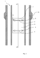
- the sensor is arranged in a positioning tool 1 comprising a detection unit 2, as shown in Fig. 2 .
- the detection unit 2 comprises two magnets 4 and four sensors 5, 6. These sensors 5, 6 are positioned so that one sensor is positioned on each side of the magnet 4.
- the sensors 5, 6 are arranged with an axial distance d 2 from each other and in the same plane 7, such as on a plate 8.
- the positioning tool 1 has a substantially cylindrical shape, and the detecting unit 2 is arranged in its centre, extending along the length the tool.
- the plate 8 is fastened to the wall of the tool 1.
- the magnetic field changes depending on the surroundings, and the sensors 5, 6 detect the direction ⁇ of the magnetic field lines when the tool moves.
- small variations are measured while the tool 1 passes the part of the casing 3 between two collars or joints as shown in Fig. 1B .
- the small variations in thickness result from the manufacturing process when making the casing by means of rolling resulting in barrel lines or rolling lines in the casing.
- the measurements come from small inaccuracies in the diameter of the roller and results in the manufacturing pattern shown in Fig. 1B having peaks in the form of local minimums and maximums.
- Each sensor 5, 6 measures the same changes, but there is a difference in time between the measurements due to the distance between the sensors.
- the data from the sensors 5, 6 is convoluted, and from the maximum value of the convolution, it can be deducted when a first sensor 5 passes the same position as a second sensor 6, and so forth.
- ⁇ t the time between calculations
- ⁇ x the estimated velocity.
- the method is relatively insensitive to noise in the measurements. In this way, a more accurate result is obtained. Furthermore, since the same characteristics are present in the two sets, the scale of the data is not important.
- the change in field direction is substantially increased.
- the distance from a collar is zero, and any errors in the estimated position of the tool can be eliminated.
- the number of past collars and the distance from the last collar indicate the determined position of the tool since the distance between collars is known. However, as mentioned, this determined position is based on the presumption that the tool moves at a constant velocity between two collars.
- Fig. 1A shows a sequence of measurements conducted by means of a sensor when moving past two casing collars.
- the sequence of measurements shows the supports of metal supporting the casing while testing in the parts marked 51 and thus the manufacturing pattern is thus only visible at a distance from the supports and the collars.
- the part of the sequence conducted when passing a casing collar is marked 52.
- the sequence of measurements showing the manufacturing pattern is marked 53 and showed in an enlarged view in Fig. 1B .
- a pattern is identified as e.g. two distances X and Y which occur at a certain point along the first casing part and subsequently, this pattern is used to adjust the velocity and thus the position of the tool between two collars.
- the pattern may be a constant thickness change so that at a certain part of the casing, a distance X between a local minimum or maximum thickness of the casing and a next local minimum or maximum thickness of the casing is identified.
- Such constant thickness variation may result from a non-circular diameter of the rollers used when manufacturing the casing by means of rolling.
- any variations in relation to such identified manufacturing pattern is used to adjust the velocity of the tool and thus correct the position at which a certain measurement of a well property is conducted.
- the manufacturing pattern is a more unique pattern as no such constant thickness change is identified.
- a pattern identified as the same from one casing part to the next when moving down the well does also give points along a second casing part at which the determined velocity and position of the tool is found and can be adjusted if needed when comparing the measured sequence of the second part of the casing with the identified manufacturing pattern if any variation is present when comparing the sequence with the identified manufacturing pattern. Adjustment of the velocity and position of the tool and a measurement of a well property can thus be more accurately determined than if carried out by means of a casing collar locator as a sequence of measurements is not just used to determine the velocity of the tool but also to compare it with an expected and identified manufacturing pattern and then to adjust the determined velocity and thus the determined position.
- the identified manufacturing pattern may only be fractions of the measurements illustrating thickness variations of a casing part and thus the pattern needs not to be identified along an entire casing part between two casing collars.
- these may be used to adjust the determined velocity and position of the tool when measuring a sequence of the a magnitude and/or direction of a magnetic field by means of a sensor while moving along a second part of the casing.
- the velocity and position determined from the sequence of the a magnitude and/or direction of a magnetic field is adjustable twice along the second part and thus twice before reaching the next collar.
- the thickness of the casing varies in a certain pattern which is identified and stored in the positioning tool as the expected pattern and compared to the determined velocity. If the expected pattern does not correspond to the measured pattern for determining the velocity of the tool, the distance variations of the measured pattern in relation to the expected pattern is determined and the measured pattern is adjusted accordingly and the velocity is recalculated or adjusted accordingly.
- the measured pattern is adjusted by adjusting the velocity accordingly by adjusting the time scale of the measurement at that local point or fraction of the sequence of measurements.
- the detecting unit 2 of Fig. 2 only has four sensors 5, 6, and two of the sensors arranged on the same side of the magnets 4 are necessary to calculate the position of the tool. The closer the two sensors 5, 6 are arranged in the longitudinal direction of the tool, the faster the measurements can be processed.
- One magnet 4 can be arranged outside a sensor 5, 6 so that the first magnet is arranged outside the first sensor and the second magnet is arranged outside the second sensor. When there is a magnet 4 outside each sensor 5, 6, all sensors are positioned with the same distance to the magnet, which results in a more precise measurement, again resulting in a better velocity estimates.
- the positioning tool may comprise a first sensor 5 and a second sensor 6, wherein the determined velocity is determined from measuring the magnitude and/or direction of the magnetic field by means of the first and subsequently the second sensor, and then comparing the measurements from the first sensor with the measurements from the second sensor in order to calculate a velocity of the tool.
- the manufacturing pattern may also result from other manufacturing processes such as mill rolling, cold drawing or hot drawing.
- fluid or well fluid any type of fluid that may be present in oil or gas wells, such as natural gas, oil, oil mud, crude oil, water etc.
- gas is meant any type of gas composition present in a well, completion or open hole
- oil is meant any type of oil composition, such as crude oil, an oil-containing fluid etc.
- Gas, oil and water fluids may therefore all comprise other elements or substances than gas, oil and/or water, respectively.
- the fluid may also be a combination of gas, oil, water and small solids in the fluid.
- a casing By a casing is meant all types of pipes, tubings, tubulars etc. used downhole in relation to oil or natural gas production.
- a downhole tractor can be used to push the tools all the way into position in the well.
- a downhole tractor is any type of driving tool capable of pushing or pulling tools in a well, such as a Well Tractor®.
Landscapes
- Physics & Mathematics (AREA)
- Life Sciences & Earth Sciences (AREA)
- Engineering & Computer Science (AREA)
- Geology (AREA)
- Mining & Mineral Resources (AREA)
- General Life Sciences & Earth Sciences (AREA)
- Geophysics (AREA)
- Environmental & Geological Engineering (AREA)
- General Physics & Mathematics (AREA)
- Geochemistry & Mineralogy (AREA)
- Fluid Mechanics (AREA)
- Remote Sensing (AREA)
- Chemical & Material Sciences (AREA)
- Electromagnetism (AREA)
- Analytical Chemistry (AREA)
- Electrochemistry (AREA)
- Health & Medical Sciences (AREA)
- Chemical Kinetics & Catalysis (AREA)
- Biochemistry (AREA)
- General Health & Medical Sciences (AREA)
- Immunology (AREA)
- Pathology (AREA)
- Measurement Of Length, Angles, Or The Like Using Electric Or Magnetic Means (AREA)
- Automatic Control Of Machine Tools (AREA)
- Geophysics And Detection Of Objects (AREA)
- Control Of Position Or Direction (AREA)
- Length Measuring Devices With Unspecified Measuring Means (AREA)
Abstract
The invention relates to a positioning method for determining a position of a downhole tool moving at a velocity in a casing in a well, comprising the steps of measuring a magnitude and/or direction of a magnetic field by means of a first sensor several times over a time period while moving along a first part of the casing manufactured from metal, determining a manufacturing pattern of the casing along the first part from the measurement, measuring a magnitude and/or direction of a magnetic field by means of the first sensor several times over a time period while moving along a second part of the casing manufactured from metal, determining the velocity of the tool along the second part, adjusting the determined velocity of the tool along the second part based upon the manufacturing pattern.
Description
- The present invention relates to a positioning method for determining the position of a tool in a casing downhole.
- When running a tool in a casing downhole, it may often be desirable to know the specific position of the tool. Especially when running different types of inspection or logging tools, it may be very important to know the exact location of each observation made during the inspection or logging. For this and several other reasons, many attempts have been made to develop a device capable of determining the position of the tool when situated downhole.
- A known device for determining the position of a tool downhole is called a "Casing collar locator". Typically, a locator comprises one or more magnets and one or more coils for measuring changes in the magnetic and electrical flux when passing a collar or casing feature significant enough to cause a measurable change. The device is thus only able to determine the position of the tool collar by collar and not between two collars, and in order to measure differences in the flux, the device must be moved with considerable speed in the casing.
- Another "Casing collar locator" comprises one or more flux gate magnetometers in the form of coils for measuring the remaining or naturally occurring magnetism in the casing collars. However, in order to determine the position of the tool between the collars, the wireline depth must be used.
- As shown in
US 6,768,299 , a "Casing collar locator" may also comprise one magnetometer for measuring changes in the strength of the magnetic field generated from a magnet. The "Casing collar locator" may also comprise more than one magnetometer to achieve different modes of detection so that one magnetometer detects collars and the other magnetometers detect the direction of the tool in order to control the direction of the drilling head of the tool. - It is an object of the present invention to wholly or partly overcome the above disadvantages and drawbacks of the prior art. More specifically, it is an object to provide an improved method capable of determining an exact position of the tool.
- The above objects, together with numerous other objects, advantages, and features, which will become evident from the below description, are accomplished by a solution in accordance with the present invention by a positioning method for determining a position of a downhole tool moving at a velocity in a casing in a well, comprising the steps of:
- measuring a magnitude and/or direction of a magnetic field by means of a first sensor several times over a time period while moving along a first part of the casing manufactured from metal,
- determining a manufacturing pattern of the casing along the first part from the measurement,
- measuring a magnitude and/or direction of a magnetic field by means of the first sensor several times over a time period while moving along a second part of the casing manufactured from metal,
- determining the velocity of the tool along the second part,
- adjusting the determined velocity of the tool along the second part based upon the manufacturing pattern.
- The step of determining a manufacturing pattern may comprise determining a cycle in the measurement coming when manufacturing the casing, such as forming the casing by means of rolling, cold drawing, rolling milling.
- Furthermore, the manufacturing pattern may be barrel or rolling lines in the casing.
- In an embodiment, the casing may be connected by means of casing collars and the first part and second part of the casing may be arranged between two collars.
- Moreover, the first part of the casing may comprise several casing sections connected by collars.
- Further, the manufacturing pattern may be thickness variations in the casing.
- Said manufacturing pattern may result from a rolling process, mill rolling, cold drawing, or hot drawing.
- In addition, the sensor may be arranged in a detecting unit arranged in a tool and comprising two magnets and two sensors being arranged with an axial distance from each other and in a same plane, such as on a plate.
- Also, the manufacturing pattern may be a distance between a local minimum or maximum thickness of the casing and a next local minimum or maximum thickness of the casing.
- Furthermore, the first sensor may have an axial distance to a second sensor and the step of determining the velocity is from a measured time period between the first sensor measuring a first point of the casing and the second detector measuring the same first point of the casing.
- Additionally, the variation of the thickness of the casing may result from a non-circular roller used when manufacturing the casing by rolling.
- The manufacturing pattern may be several fractions identified along the first part of the casing.
- Moreover, the method according to the present invention may comprise the steps of:
- measuring the magnitude and/or direction of the magnetic field by means of the second sensor, and
- comparing the measurements from the first sensor with the measurements from the second sensor in order to calculate a velocity of the tool.
- Said step of measuring the magnitude and/or direction of the magnetic field may be performed several times over a time period, and the step of comparing the measurements from the sensor may be performed after this time period.
- The present invention also relates to a system for carrying out the method as described above.
- Also, the present invention relates to use of the method as described above for accurately displaying a condition downhole in real time.
- Finally, the present invention relates to use of the method as described above for accurately displaying a position downhole in real time.
By accurately is meant that the displaying of the condition is more accurate than if carried out by means of a casing collar locator. - The invention and its many advantages will be described in more detail below with reference to the accompanying schematic drawings, which for the purpose of illustration show some non-limiting embodiments and in which
-
Fig. 1A shows a sequence of measurement by a sensor, -
Fig. 1B shows an enlarged view of part of the sequence shown inFig. 1A , and -
Fig. 2 shows a positioning tool. - All these figures are highly schematic and not necessarily to scale, and they show only those parts which are necessary in order to elucidate the invention, other parts being omitted or merely suggested.
- The present invention relates to a positioning method for determining a position of a downhole tool moving at a velocity in a casing in a well also in between two casing collars. When a downhole tool is conducting certain measurements of the well properties, such as the well flow, fluid characteristics, temperature, the pressure etc., the measurements are each conducted at a certain time and position along the casing. However, if the position is not accurate do to the fact that the tool moves at another velocity than expected, the measurements give an inaccurate picture of the well properties. When using present positioning tools, such as a casing collar locator, the position is adjusted when passing a casing collar and the position from passing the last casing collar is adjusted accordingly. However, such an adjustment presumes that the variation of tool velocity has been constant between the last and present casing collar, and this may not always be the case and in such a case the measured well properties are not providing an accurate picture of the well.
- In the position method of the present invention, a magnitude and/or direction of a magnetic field is measured by means of a first sensor several times over a time period while moving along a first part of the casing manufactured from metal as shown in
Figs. 1A and 1B . The sensor is arranged in apositioning tool 1 comprising adetection unit 2, as shown inFig. 2 . Thedetection unit 2 comprises twomagnets 4 and foursensors sensors magnet 4. Thesensors plate 8. - The
positioning tool 1 has a substantially cylindrical shape, and the detectingunit 2 is arranged in its centre, extending along the length the tool. Theplate 8 is fastened to the wall of thetool 1. When thetool 1 moves down the casing 3, the magnetic field changes depending on the surroundings, and thesensors tool 1 passes the part of the casing 3 between two collars or joints as shown inFig. 1B . The small variations in thickness result from the manufacturing process when making the casing by means of rolling resulting in barrel lines or rolling lines in the casing. The measurements come from small inaccuracies in the diameter of the roller and results in the manufacturing pattern shown inFig. 1B having peaks in the form of local minimums and maximums. - Each
sensor sensors first sensor 5 passes the same position as asecond sensor 6, and so forth. The period between the point in time when the first and the second sensor pass the same positions is named ΔT, and since the distance d2 between thefirst sensor 5 and thesecond sensor 6 is known, it is possible to calculate the velocity of thepositioning tool 1 by means of the following equation:
- The estimate of the velocity is based on a number of measurements, and by continuously calculating the velocity of the
tool 1, it is possible to calculate the distance Δx travelled since the previous calculation by means of the following equation:
where Δt is the time between calculations and Δx is the estimated velocity. When adding these estimated distances, the distance from the top of the well at a specific time of e.g. an observation of an irregularity, such as a leak, is known. - Using convolution between datasets received from at least two sensors instead of only comparing the measurements from one sensor with measurements from the other measurement by measurement, the method is relatively insensitive to noise in the measurements. In this way, a more accurate result is obtained. Furthermore, since the same characteristics are present in the two sets, the scale of the data is not important.
- When the
tool 1 passes a joint or collar where two casing parts are mounted together, the change in field direction is substantially increased. At this point, the distance from a collar is zero, and any errors in the estimated position of the tool can be eliminated. The number of past collars and the distance from the last collar indicate the determined position of the tool since the distance between collars is known. However, as mentioned, this determined position is based on the presumption that the tool moves at a constant velocity between two collars. -
Fig. 1A shows a sequence of measurements conducted by means of a sensor when moving past two casing collars. Unfortunately, the sequence of measurements shows the supports of metal supporting the casing while testing in the parts marked 51 and thus the manufacturing pattern is thus only visible at a distance from the supports and the collars. The part of the sequence conducted when passing a casing collar is marked 52. Thus, the sequence of measurements showing the manufacturing pattern is marked 53 and showed in an enlarged view inFig. 1B . - In
Fig. 1B , a pattern is identified as e.g. two distances X and Y which occur at a certain point along the first casing part and subsequently, this pattern is used to adjust the velocity and thus the position of the tool between two collars. When moving down the well, the positioning tool passes many casing parts between two collars and thus, the manufacturing pattern is identified when passing these first parts. The pattern may be a constant thickness change so that at a certain part of the casing, a distance X between a local minimum or maximum thickness of the casing and a next local minimum or maximum thickness of the casing is identified. Such constant thickness variation may result from a non-circular diameter of the rollers used when manufacturing the casing by means of rolling. Subsequently, when passing a second casing part, any variations in relation to such identified manufacturing pattern is used to adjust the velocity of the tool and thus correct the position at which a certain measurement of a well property is conducted. - In another case, the manufacturing pattern is a more unique pattern as no such constant thickness change is identified. However, a pattern identified as the same from one casing part to the next when moving down the well does also give points along a second casing part at which the determined velocity and position of the tool is found and can be adjusted if needed when comparing the measured sequence of the second part of the casing with the identified manufacturing pattern if any variation is present when comparing the sequence with the identified manufacturing pattern. Adjustment of the velocity and position of the tool and a measurement of a well property can thus be more accurately determined than if carried out by means of a casing collar locator as a sequence of measurements is not just used to determine the velocity of the tool but also to compare it with an expected and identified manufacturing pattern and then to adjust the determined velocity and thus the determined position.
- The identified manufacturing pattern may only be fractions of the measurements illustrating thickness variations of a casing part and thus the pattern needs not to be identified along an entire casing part between two casing collars. By having some identifiable manufacturing pattern fractions along a casing part, these may be used to adjust the determined velocity and position of the tool when measuring a sequence of the a magnitude and/or direction of a magnetic field by means of a sensor while moving along a second part of the casing. When having e.g. two identified manufacturing pattern fractions along a casing part, the velocity and position determined from the sequence of the a magnitude and/or direction of a magnetic field is adjustable twice along the second part and thus twice before reaching the next collar.
- When producing the casing by means of rollers, the thickness of the casing varies in a certain pattern which is identified and stored in the positioning tool as the expected pattern and compared to the determined velocity. If the expected pattern does not correspond to the measured pattern for determining the velocity of the tool, the distance variations of the measured pattern in relation to the expected pattern is determined and the measured pattern is adjusted accordingly and the velocity is recalculated or adjusted accordingly.
- If the identified manufacturing pattern is a constant distance X between e.g. a local maximum thickness of the casing and a next local maximum thickness of the casing along the entire casing part between two casing collars, the measured pattern is adjusted by adjusting the velocity accordingly by adjusting the time scale of the measurement at that local point or fraction of the sequence of measurements.
- The detecting
unit 2 ofFig. 2 only has foursensors magnets 4 are necessary to calculate the position of the tool. The closer the twosensors magnet 4 can be arranged outside asensor magnet 4 outside eachsensor - Thus, the positioning tool may comprise a
first sensor 5 and asecond sensor 6, wherein the determined velocity is determined from measuring the magnitude and/or direction of the magnetic field by means of the first and subsequently the second sensor, and then comparing the measurements from the first sensor with the measurements from the second sensor in order to calculate a velocity of the tool. - The manufacturing pattern may also result from other manufacturing processes such as mill rolling, cold drawing or hot drawing.
- By fluid or well fluid is meant any type of fluid that may be present in oil or gas wells, such as natural gas, oil, oil mud, crude oil, water etc. By gas is meant any type of gas composition present in a well, completion or open hole, and by oil is meant any type of oil composition, such as crude oil, an oil-containing fluid etc. Gas, oil and water fluids may therefore all comprise other elements or substances than gas, oil and/or water, respectively. The fluid may also be a combination of gas, oil, water and small solids in the fluid.
- By a casing is meant all types of pipes, tubings, tubulars etc. used downhole in relation to oil or natural gas production.
- In the event that the tools are not submergible all the way into the casing, a downhole tractor can be used to push the tools all the way into position in the well. A downhole tractor is any type of driving tool capable of pushing or pulling tools in a well, such as a Well Tractor®.
- Although the invention has been described in the above in connection with preferred embodiments of the invention, it will be evident for a person skilled in the art that several modifications are conceivable without departing from the invention as defined by the following claims.
Claims (15)
- A positioning method for determining a position of a downhole tool moving at a velocity in a casing in a well, comprising the steps of:- measuring a magnitude and/or direction of a magnetic field by means of a first sensor several times over a time period while moving along a first part of the casing manufactured from metal,- determining a manufacturing pattern of the casing along the first part from the measurement,- measuring a magnitude and/or direction of a magnetic field by means of the first sensor several times over a time period while moving along a second part of the casing manufactured from metal,- determining the velocity of the tool along the second part,- adjusting the determined velocity of the tool along the second part based upon the manufacturing pattern.
- A positioning method according to claim 1, wherein the casing is connected by means of casing collars and the first part and second part of the casing are arranged between two collars.
- A positioning method according to claim 1, wherein the first part of the casing comprises several casing sections connected by collars.
- A positioning method according to any of the preceding claims, wherein the manufacturing pattern is thickness variations in the casing.
- A positioning method according to any of the preceding claims, wherein the manufacturing pattern results from a rolling process, mill rolling, cold drawing, or hot drawing.
- A positioning method according to any of the preceding claims, wherein the sensor is arranged in a detecting unit which is arranged in a tool (1) and comprises two magnets (4) and two sensors (5, 6) being arranged with an axial distance (d2) from each other and in a same plane (7), such as on a plate (8).
- A positioning method according to any of the preceding claims, wherein the manufacturing pattern is a distance between a local minimum or maximum thickness of the casing and a next local minimum or maximum thickness of the casing.
- A positioning method according to any of the preceding claims, wherein the first sensor has an axial distance to a second sensor and the step of determining the velocity is from a measured time period between the first sensor measuring a first point of the casing and the second detector measuring the same first point of the casing.
- A positioning method according to claim 4, wherein the variation of the thickness of the casing results from a non-circular roller used when manufacturing the casing by rolling.
- A positioning method according to any of the preceding claims, wherein the manufacturing pattern is several fractions identified along the first part of the casing.
- A method according to any of the preceding claims, comprising the steps of:- measuring the magnitude and/or direction of the magnetic field by means of the second sensor, and- comparing the measurements from the first sensor with the measurements from the second sensor in order to calculate a velocity of the tool.
- A method according to claim 11, wherein the step of measuring the magnitude and/or direction of the magnetic field is performed several times over a time period, and wherein the step of comparing the measurements from the sensor is performed after this time period.
- A system for carrying out the method according to any of claims 1-12.
- Use of the method according to any of claims 1-12 for accurately displaying a condition downhole in real time.
- Use of the method according to any of claims 1-12 for accurately displaying a position downhole in real time.
Priority Applications (12)
| Application Number | Priority Date | Filing Date | Title |
|---|---|---|---|
| EP11173403A EP2546456A1 (en) | 2011-07-11 | 2011-07-11 | Positioning method |
| RU2014103875A RU2610450C2 (en) | 2011-07-11 | 2012-07-11 | Method of location determination |
| CN201280034250.6A CN103649461B (en) | 2011-07-11 | 2012-07-11 | positioning method |
| CA2841225A CA2841225A1 (en) | 2011-07-11 | 2012-07-11 | Positioning method |
| MX2014000086A MX352392B (en) | 2011-07-11 | 2012-07-11 | Positioning method. |
| DK12733723.6T DK2732131T3 (en) | 2011-07-11 | 2012-07-11 | POSITIONING METHOD |
| AU2012282565A AU2012282565B2 (en) | 2011-07-11 | 2012-07-11 | Positioning method |
| EP12733723.6A EP2732131B1 (en) | 2011-07-11 | 2012-07-11 | Positioning method |
| MYPI2013004718A MY167172A (en) | 2011-07-11 | 2012-07-11 | Positioning method |
| PCT/EP2012/063534 WO2013007739A1 (en) | 2011-07-11 | 2012-07-11 | Positioning method |
| US14/131,750 US9726005B2 (en) | 2011-07-11 | 2012-07-11 | Positioning method and tool for determining the position of the tool in a casing downhole |
| BR112014000575-3A BR112014000575B1 (en) | 2011-07-11 | 2012-07-11 | POSITIONING METHOD AND TOOL |
Applications Claiming Priority (1)
| Application Number | Priority Date | Filing Date | Title |
|---|---|---|---|
| EP11173403A EP2546456A1 (en) | 2011-07-11 | 2011-07-11 | Positioning method |
Publications (1)
| Publication Number | Publication Date |
|---|---|
| EP2546456A1 true EP2546456A1 (en) | 2013-01-16 |
Family
ID=46506404
Family Applications (2)
| Application Number | Title | Priority Date | Filing Date |
|---|---|---|---|
| EP11173403A Withdrawn EP2546456A1 (en) | 2011-07-11 | 2011-07-11 | Positioning method |
| EP12733723.6A Active EP2732131B1 (en) | 2011-07-11 | 2012-07-11 | Positioning method |
Family Applications After (1)
| Application Number | Title | Priority Date | Filing Date |
|---|---|---|---|
| EP12733723.6A Active EP2732131B1 (en) | 2011-07-11 | 2012-07-11 | Positioning method |
Country Status (11)
| Country | Link |
|---|---|
| US (1) | US9726005B2 (en) |
| EP (2) | EP2546456A1 (en) |
| CN (1) | CN103649461B (en) |
| AU (1) | AU2012282565B2 (en) |
| BR (1) | BR112014000575B1 (en) |
| CA (1) | CA2841225A1 (en) |
| DK (1) | DK2732131T3 (en) |
| MX (1) | MX352392B (en) |
| MY (1) | MY167172A (en) |
| RU (1) | RU2610450C2 (en) |
| WO (1) | WO2013007739A1 (en) |
Cited By (1)
| Publication number | Priority date | Publication date | Assignee | Title |
|---|---|---|---|---|
| CN103412343A (en) * | 2013-08-27 | 2013-11-27 | 哈尔滨工业大学 | Oil well casing coupling detection method based on magnetic positioning signal feature recognition |
Families Citing this family (23)
| Publication number | Priority date | Publication date | Assignee | Title |
|---|---|---|---|---|
| CN105492721B (en) | 2013-08-26 | 2018-10-02 | 德国德力能有限公司 | Perforating gun and detonator assembly |
| US9540927B2 (en) * | 2014-04-04 | 2017-01-10 | Micro-G Lacoste, Inc. | High resolution continuous depth positioning in a well bore using persistent casing properties |
| CN104179490B (en) * | 2014-08-06 | 2017-02-15 | 中国石油集团渤海钻探工程有限公司 | In-well proofreading method for horizontal well communicating equipment |
| GB2531782A (en) * | 2014-10-30 | 2016-05-04 | Roxar Flow Measurement As | Position indicator for determining the relative position and/or movement of downhole tool componenets and method thereof |
| CA3015356A1 (en) * | 2016-02-23 | 2017-08-31 | Hunting Titan, Inc. | Differential velocity sensor |
| CN106150483A (en) * | 2016-06-23 | 2016-11-23 | 中国石油集团川庆钻探工程有限公司 | Identification method for tubing string coupling in gas well under-pressure operation |
| EP3263832A1 (en) | 2016-06-30 | 2018-01-03 | Openfield | Method and device for depth positioning downhole tool and associated measurement log of a hydrocarbon well |
| CN107882550B (en) * | 2017-11-15 | 2021-06-11 | 烟台杰瑞石油装备技术有限公司 | Airtight well head coupling detection device |
| US11274546B2 (en) * | 2018-02-23 | 2022-03-15 | Hunting Titan, Inc. | Autonomous tool |
| US12031417B2 (en) | 2018-05-31 | 2024-07-09 | DynaEnergetics Europe GmbH | Untethered drone string for downhole oil and gas wellbore operations |
| US11905823B2 (en) | 2018-05-31 | 2024-02-20 | DynaEnergetics Europe GmbH | Systems and methods for marker inclusion in a wellbore |
| US11434713B2 (en) | 2018-05-31 | 2022-09-06 | DynaEnergetics Europe GmbH | Wellhead launcher system and method |
| US11591885B2 (en) | 2018-05-31 | 2023-02-28 | DynaEnergetics Europe GmbH | Selective untethered drone string for downhole oil and gas wellbore operations |
| US11661824B2 (en) | 2018-05-31 | 2023-05-30 | DynaEnergetics Europe GmbH | Autonomous perforating drone |
| US11408279B2 (en) | 2018-08-21 | 2022-08-09 | DynaEnergetics Europe GmbH | System and method for navigating a wellbore and determining location in a wellbore |
| US11808093B2 (en) | 2018-07-17 | 2023-11-07 | DynaEnergetics Europe GmbH | Oriented perforating system |
| WO2020038848A1 (en) | 2018-08-20 | 2020-02-27 | DynaEnergetics Europe GmbH | System and method to deploy and control autonomous devices |
| WO2020251522A1 (en) * | 2019-06-10 | 2020-12-17 | Halliburton Energy Services, Inc. | Differential casing collar locator |
| EP3999712A1 (en) | 2019-07-19 | 2022-05-25 | DynaEnergetics Europe GmbH | Ballistically actuated wellbore tool |
| US11946728B2 (en) | 2019-12-10 | 2024-04-02 | DynaEnergetics Europe GmbH | Initiator head with circuit board |
| CN113153276B (en) | 2021-05-20 | 2023-11-21 | 烟台杰瑞石油装备技术有限公司 | Ferromagnetic object detection device and method for detecting tubing coupling |
| US12312925B2 (en) | 2021-12-22 | 2025-05-27 | DynaEnergetics Europe GmbH | Manually oriented internal shaped charge alignment system and method of use |
| US12210131B2 (en) * | 2023-05-19 | 2025-01-28 | Fmc Technologies, Inc. | Seal pocket detection assembly |
Citations (5)
| Publication number | Priority date | Publication date | Assignee | Title |
|---|---|---|---|---|
| US4808925A (en) * | 1987-11-19 | 1989-02-28 | Halliburton Company | Three magnet casing collar locator |
| GB2310042A (en) * | 1996-02-05 | 1997-08-13 | Applied Tech Ass | Casing joint locator and counter |
| WO2003087536A1 (en) * | 2002-04-12 | 2003-10-23 | Halliburton Energy Services, Inc. | Magnetically activated well tool |
| US6768299B2 (en) | 2001-12-20 | 2004-07-27 | Schlumberger Technology Corporation | Downhole magnetic-field based feature detector |
| EP2317071A1 (en) * | 2009-10-30 | 2011-05-04 | Welltec A/S | Positioning tool |
Family Cites Families (33)
| Publication number | Priority date | Publication date | Assignee | Title |
|---|---|---|---|---|
| US2717039A (en) * | 1952-09-02 | 1955-09-06 | Ford Alexander Corp | Detector device for exploring ferromagnetic structure in well bores |
| US2967994A (en) * | 1957-03-25 | 1961-01-10 | Well Surveys Inc | Casing joint locator |
| US3015063A (en) * | 1960-06-23 | 1961-12-26 | Camco Inc | Magnetic caliper |
| US3434046A (en) * | 1965-12-20 | 1969-03-18 | Halliburton Co | Electronic borehole casing collar locator |
| US3570594A (en) * | 1969-03-13 | 1971-03-16 | Howell M Hamilton | Subsurface control apparatus for use in oil and gas wells |
| US3843923A (en) * | 1973-07-05 | 1974-10-22 | Stewart & Stevenson Inc Jim | Well pipe joint locator using a ring magnet and two sets of hall detectors surrounding the pipe |
| US4110688A (en) * | 1976-09-20 | 1978-08-29 | Monitoring Systems, Inc. | Method and apparatus for pipe joint locator, counter and displacement calculator |
| US4292589A (en) * | 1979-05-09 | 1981-09-29 | Schlumberger Technology Corporation | Eddy current method and apparatus for inspecting ferromagnetic tubular members |
| US4540941A (en) * | 1983-08-12 | 1985-09-10 | Dresser Industries, Inc. | Casing collar indicator for operation in centralized or decentralized position |
| GB9101631D0 (en) * | 1991-01-25 | 1991-03-06 | Chardec Consultants Ltd | Improvements in remote sensing |
| US5279366A (en) * | 1992-09-01 | 1994-01-18 | Scholes Patrick L | Method for wireline operation depth control in cased wells |
| KR19980020514A (en) | 1996-09-09 | 1998-06-25 | 김광호 | Implementing Fault Tolerance of Private Switching System of Integrated Telecommunication Network |
| US6411084B1 (en) * | 1999-04-05 | 2002-06-25 | Halliburton Energy Services, Inc. | Magnetically activated well tool |
| US6896056B2 (en) * | 2001-06-01 | 2005-05-24 | Baker Hughes Incorporated | System and methods for detecting casing collars |
| US7204308B2 (en) | 2004-03-04 | 2007-04-17 | Halliburton Energy Services, Inc. | Borehole marking devices and methods |
| EP1669769A1 (en) * | 2004-12-13 | 2006-06-14 | Services Pétroliers Schlumberger | A magneto-optical sensor |
| GB2422622A (en) * | 2005-01-31 | 2006-08-02 | Pathfinder Energy Services Inc | Method For Locating Casing Joints Using A Measurement While Drilling Tool |
| US7347261B2 (en) * | 2005-09-08 | 2008-03-25 | Schlumberger Technology Corporation | Magnetic locator systems and methods of use at a well site |
| RU2298646C1 (en) * | 2005-09-27 | 2007-05-10 | Общество с ограниченной ответственностью "Оренбурггеофизика" | Method for well depth measurement during well survey |
| BRPI0709703A2 (en) * | 2006-03-27 | 2011-07-26 | Key Energy Services Inc | Method and system for assessing and displaying depth data |
| US8174258B2 (en) * | 2006-03-29 | 2012-05-08 | Dolphin Measurement Systems Llc | Method and system for measurement of parameters of a flat material |
| GB0620251D0 (en) * | 2006-10-12 | 2006-11-22 | Antech Ltd | Well downhole condition signalling |
| US7622916B2 (en) * | 2006-12-20 | 2009-11-24 | Schlumberger Technology Corporation | Detector |
| FR2914007B1 (en) * | 2007-03-20 | 2009-05-29 | Geo Energy Sa | PROBE FOR ANALYZING AN ASSEMBLY OF RODS OR TUBES |
| US20080236819A1 (en) * | 2007-03-28 | 2008-10-02 | Weatherford/Lamb, Inc. | Position sensor for determining operational condition of downhole tool |
| US8065085B2 (en) * | 2007-10-02 | 2011-11-22 | Gyrodata, Incorporated | System and method for measuring depth and velocity of instrumentation within a wellbore using a bendable tool |
| US8201625B2 (en) * | 2007-12-26 | 2012-06-19 | Schlumberger Technology Corporation | Borehole imaging and orientation of downhole tools |
| US8136395B2 (en) * | 2007-12-31 | 2012-03-20 | Schlumberger Technology Corporation | Systems and methods for well data analysis |
| US8134360B2 (en) * | 2008-03-26 | 2012-03-13 | William Marsh Rice University | Measurement of pipe wall thickness using magnetic flux leakage signals |
| EP2310628B1 (en) | 2008-06-26 | 2014-08-27 | Schlumberger Technology B.V. | Detecting a structure in a well |
| RU2405105C2 (en) * | 2008-12-11 | 2010-11-27 | Общество С Ограниченной Ответственностью "Газпром Трансгаз-Кубань" | Active collar locator |
| US9127532B2 (en) * | 2011-09-07 | 2015-09-08 | Halliburton Energy Services, Inc. | Optical casing collar locator systems and methods |
| US20130249705A1 (en) * | 2012-03-21 | 2013-09-26 | Halliburton Energy Services, Inc. | Casing collar locator with wireless telemetry support |
-
2011
- 2011-07-11 EP EP11173403A patent/EP2546456A1/en not_active Withdrawn
-
2012
- 2012-07-11 WO PCT/EP2012/063534 patent/WO2013007739A1/en not_active Ceased
- 2012-07-11 BR BR112014000575-3A patent/BR112014000575B1/en active IP Right Grant
- 2012-07-11 AU AU2012282565A patent/AU2012282565B2/en active Active
- 2012-07-11 DK DK12733723.6T patent/DK2732131T3/en active
- 2012-07-11 MY MYPI2013004718A patent/MY167172A/en unknown
- 2012-07-11 CA CA2841225A patent/CA2841225A1/en not_active Abandoned
- 2012-07-11 RU RU2014103875A patent/RU2610450C2/en active
- 2012-07-11 US US14/131,750 patent/US9726005B2/en active Active
- 2012-07-11 EP EP12733723.6A patent/EP2732131B1/en active Active
- 2012-07-11 CN CN201280034250.6A patent/CN103649461B/en not_active Expired - Fee Related
- 2012-07-11 MX MX2014000086A patent/MX352392B/en active IP Right Grant
Patent Citations (5)
| Publication number | Priority date | Publication date | Assignee | Title |
|---|---|---|---|---|
| US4808925A (en) * | 1987-11-19 | 1989-02-28 | Halliburton Company | Three magnet casing collar locator |
| GB2310042A (en) * | 1996-02-05 | 1997-08-13 | Applied Tech Ass | Casing joint locator and counter |
| US6768299B2 (en) | 2001-12-20 | 2004-07-27 | Schlumberger Technology Corporation | Downhole magnetic-field based feature detector |
| WO2003087536A1 (en) * | 2002-04-12 | 2003-10-23 | Halliburton Energy Services, Inc. | Magnetically activated well tool |
| EP2317071A1 (en) * | 2009-10-30 | 2011-05-04 | Welltec A/S | Positioning tool |
Cited By (1)
| Publication number | Priority date | Publication date | Assignee | Title |
|---|---|---|---|---|
| CN103412343A (en) * | 2013-08-27 | 2013-11-27 | 哈尔滨工业大学 | Oil well casing coupling detection method based on magnetic positioning signal feature recognition |
Also Published As
| Publication number | Publication date |
|---|---|
| US20140152298A1 (en) | 2014-06-05 |
| MY167172A (en) | 2018-08-13 |
| BR112014000575B1 (en) | 2021-04-06 |
| US9726005B2 (en) | 2017-08-08 |
| MX2014000086A (en) | 2014-05-01 |
| EP2732131B1 (en) | 2019-06-19 |
| BR112014000575A2 (en) | 2017-02-14 |
| EP2732131A1 (en) | 2014-05-21 |
| CN103649461A (en) | 2014-03-19 |
| MX352392B (en) | 2017-11-22 |
| RU2014103875A (en) | 2015-08-20 |
| WO2013007739A1 (en) | 2013-01-17 |
| CN103649461B (en) | 2018-12-04 |
| DK2732131T3 (en) | 2019-09-23 |
| AU2012282565A1 (en) | 2013-11-28 |
| AU2012282565B2 (en) | 2016-04-14 |
| RU2610450C2 (en) | 2017-02-13 |
| CA2841225A1 (en) | 2013-01-17 |
Similar Documents
| Publication | Publication Date | Title |
|---|---|---|
| EP2732131B1 (en) | Positioning method | |
| EP2494150B1 (en) | Positioning tool | |
| US11629588B2 (en) | Method and device for depth positioning downhole tool and associated measurement log of a hydrocarbon well | |
| EP2607621A1 (en) | Downhole mapping system | |
| US20120193144A1 (en) | Magnetic ranging system for controlling a drilling process | |
| US20160161627A1 (en) | Holographic techniques for corrosion evaluation of wellbore pipes | |
| WO2017011078A1 (en) | High quality visualization in a corrosion inspection tool for multiple pipes | |
| US12571298B2 (en) | Inversion-based combined collocated (time-domain) and multi-frequency non-collocated sensor data processing for evaluating casings | |
| BR112019021080B1 (en) | SYSTEM FOR EVALUATING AN UNDERGROUND EARTH FORMATION, AND, METHODS OF EVALUATING AN UNDERGROUND EARTH FORMATION AND DIRECTING A DRILLING DRILL IN AN UNDERGROUND EARTH FORMATION. | |
| US20220334286A1 (en) | Determining a location of a tool in a tubular | |
| EP4010560A1 (en) | Sensor arrangement | |
| EP2678597B1 (en) | Position make-up indicator system | |
| EP2647790B1 (en) | Calibrator for a downhole caliper and method of using same | |
| Pöllänen et al. | Difference flow and electric conductivity measurements at the Olkiluoto site in Eurajoki, boreholes KR29, KR29B, KR30, KR31, KR31B, KR32, KR33 and KR33B |
Legal Events
| Date | Code | Title | Description |
|---|---|---|---|
| PUAI | Public reference made under article 153(3) epc to a published international application that has entered the european phase |
Free format text: ORIGINAL CODE: 0009012 |
|
| AK | Designated contracting states |
Kind code of ref document: A1 Designated state(s): AL AT BE BG CH CY CZ DE DK EE ES FI FR GB GR HR HU IE IS IT LI LT LU LV MC MK MT NL NO PL PT RO RS SE SI SK SM TR |
|
| AX | Request for extension of the european patent |
Extension state: BA ME |
|
| STAA | Information on the status of an ep patent application or granted ep patent |
Free format text: STATUS: THE APPLICATION IS DEEMED TO BE WITHDRAWN |
|
| 18D | Application deemed to be withdrawn |
Effective date: 20130717 |