EP2546156A1 - Crate cover and blank - Google Patents
Crate cover and blank Download PDFInfo
- Publication number
- EP2546156A1 EP2546156A1 EP12175896A EP12175896A EP2546156A1 EP 2546156 A1 EP2546156 A1 EP 2546156A1 EP 12175896 A EP12175896 A EP 12175896A EP 12175896 A EP12175896 A EP 12175896A EP 2546156 A1 EP2546156 A1 EP 2546156A1
- Authority
- EP
- European Patent Office
- Prior art keywords
- panel
- crate
- aperture
- disposed
- locking mechanisms
- Prior art date
- Legal status (The legal status is an assumption and is not a legal conclusion. Google has not performed a legal analysis and makes no representation as to the accuracy of the status listed.)
- Withdrawn
Links
Images







Classifications
-
- B—PERFORMING OPERATIONS; TRANSPORTING
- B65—CONVEYING; PACKING; STORING; HANDLING THIN OR FILAMENTARY MATERIAL
- B65D—CONTAINERS FOR STORAGE OR TRANSPORT OF ARTICLES OR MATERIALS, e.g. BAGS, BARRELS, BOTTLES, BOXES, CANS, CARTONS, CRATES, DRUMS, JARS, TANKS, HOPPERS, FORWARDING CONTAINERS; ACCESSORIES, CLOSURES, OR FITTINGS THEREFOR; PACKAGING ELEMENTS; PACKAGES
- B65D1/00—Rigid or semi-rigid containers having bodies formed in one piece, e.g. by casting metallic material, by moulding plastics, by blowing vitreous material, by throwing ceramic material, by moulding pulped fibrous material or by deep-drawing operations performed on sheet material
- B65D1/22—Boxes or like containers with side walls of substantial depth for enclosing contents
- B65D1/24—Boxes or like containers with side walls of substantial depth for enclosing contents with moulded compartments or partitions
- B65D1/243—Crates for bottles or like containers
-
- B—PERFORMING OPERATIONS; TRANSPORTING
- B65—CONVEYING; PACKING; STORING; HANDLING THIN OR FILAMENTARY MATERIAL
- B65D—CONTAINERS FOR STORAGE OR TRANSPORT OF ARTICLES OR MATERIALS, e.g. BAGS, BARRELS, BOTTLES, BOXES, CANS, CARTONS, CRATES, DRUMS, JARS, TANKS, HOPPERS, FORWARDING CONTAINERS; ACCESSORIES, CLOSURES, OR FITTINGS THEREFOR; PACKAGING ELEMENTS; PACKAGES
- B65D2501/00—Containers having bodies formed in one piece
- B65D2501/24—Boxes or like containers with moulded compartments or partitions
- B65D2501/24006—Details relating to bottle crates
- B65D2501/24859—Covers
-
- B—PERFORMING OPERATIONS; TRANSPORTING
- B65—CONVEYING; PACKING; STORING; HANDLING THIN OR FILAMENTARY MATERIAL
- B65D—CONTAINERS FOR STORAGE OR TRANSPORT OF ARTICLES OR MATERIALS, e.g. BAGS, BARRELS, BOTTLES, BOXES, CANS, CARTONS, CRATES, DRUMS, JARS, TANKS, HOPPERS, FORWARDING CONTAINERS; ACCESSORIES, CLOSURES, OR FITTINGS THEREFOR; PACKAGING ELEMENTS; PACKAGES
- B65D2501/00—Containers having bodies formed in one piece
- B65D2501/24—Boxes or like containers with moulded compartments or partitions
- B65D2501/24006—Details relating to bottle crates
- B65D2501/24866—Other details
- B65D2501/24872—Information, identification or detection means
- B65D2501/24878—Labels
Definitions
- the present invention relates to a package, crate cover and blank forming the same, more specifically, but not exclusively to an advertising panel having a locking mechanism for engaging with a crate.
- the present invention seek to overcome or at least mitigate the problems of the prior art.
- a package for holding one or more articles, the package comprising one or more apertures disposed in one or more walls of the package, the package comprising a detachable display panel comprising a main panel and first and second locking mechanisms, each of the first and second locking mechanisms being hingedly connected to the main panel and being folded with respect to the main panel, the main panel being disposed in face contacting relationship with an outer surface of the package and at least a portion of each of the first and second locking mechanisms each being inserted into an aperture, of the one or more apertures, each of the first and second locking mechanisms comprising at least one tab in engagement with an inner surface of the package.
- the package comprises one or more article receiving structures hingedly connected to the main panel.
- the first and second locking mechanisms are inserted into the same aperture.
- the or each article receiving structure comprises a top panel hingedly connected to an inner panel which is hingedly connected to an article receiving panel, the top panel disposed on an upper edge of the package, the inner panel disposed in face contacting relationship with an inner surface of the package, and the article receiving panel comprising an aperture into which an upper portion of an article is received.
- the article receiving panel is disposed at an elevation below the upper edge of the package.
- the main panel comprises one or more fold lines, the one or more fold line being aligned with a respective corner of the package.
- the article receiving panel comprises a first series of tabs disposed about the periphery of the article receiving aperture.
- the article receiving panel comprises a second series of tabs disposed about the article receiving aperture, wherein each tab of the second series of tabs is struck from a tab of the first series of tabs.
- the article receiving panel engages a flange or protrusion of an article or article closure.
- a display panel for a crate comprising a main panel and first and second locking mechanisms hingedly connected thereto, each of the first and second locking mechanisms being foldable with respect to the main panel for insertion into an aperture or respective aperture disposed in a wall of the crate, the first and second locking mechanisms each comprising at least one tab for engaging an inner surface of the crate.
- a blank for forming a display panel comprising a main panel and a first locking panel and a second locking panel hingedly connected thereto each of first and second locking panels forming first and second locking mechanisms respectively, the first and second locking panels each comprising at least one tab for engaging an inner surface of the crate when each of the first and second locking mechanisms are folded and inserted into an aperture or respective aperture disposed in a wall of the crate.
- FIG. 1 and Figure 2 there is shown a plan view of a blank 10 capable of forming a display panel or cover for a crate C for packaging one or more articles B such as cans or bottles.
- Blank 10 comprises a first main panel 12 and a second main panel 14 hingedly connected to one another by a fold line 13.
- a first article engaging mechanism E1 is hinged to a first, upper, end edge of first main panel 12.
- First article engaging mechanism E1 comprises a first article receiving panel 20 hingedly connected to a first inner panel 24 along a fold line 19.
- First inner panel 24 is hinged to a top panel 28 by fold line 23.
- Top panel 28 is hingedly connected to the first main panel 12 along a fold line 27.
- a second article engaging mechanism E2 is hinged to a first, upper, end edge of second main panel 14.
- Second article engaging mechanism E2 comprises a second article receiving panel 22 hingedly connected to a second inner panel 26 along a fold line 21.
- First inner panel 26 is hinged to a top panel 30 by fold line 25.
- Top panel 30 is hingedly connected to the main panel along a fold line 29.
- the first and second article receiving panels 20, 22 each comprise an article receiving aperture 40.
- a plurality of major tabs 42 defined in part by radial cut lines 48, are disposed about the perimeter of each of the article receiving apertures 40.
- a plurality of minor tabs 46 are provided about the perimeter of each of the article receiving apertures 40. Each minor tab 46 is struck from a respective one of the major tabs 42.
- Each of the major tabs 42 is substantially trapezoidal in shape.
- Each of the minor tabs 46 is defined in part by an arcuate cut line 44 and is substantially D-shaped. The major tabs 42 and the minor tabs 40 are hingedly coupled to the first or second article receiving panel 20, 22.
- First main panel 12 comprises a first locking mechanism 16, the first locking mechanism 16 is hinged to a side edge of the first main panel 12 along a fold line 15.
- First locking mechanism 16 comprises upper and lower tabs 64, 58 respectively.
- the upper and lower tabs 64, 58 are separated from the first main panel 12 by a cut line, and are preferably in a spaced apart relationship with the first main panel 12.
- a recess 62 is provided in the upper tab 64 adjacent the fold line 15.
- a recess 60 is provided in the lower tab 58 adjacent the fold line 15.
- the recess 62, 60 define engaging edges in the upper and lower tabs 64, 58 for securing the first main panel 12 to a crate C.
- Second main panel 14 comprises a second locking mechanism 18, the second locking mechanism 18 is hinged to a side edge of the second main panel 14 along a fold line 17.
- Second locking mechanism 18 comprises upper and lower tabs 54, 56 respectively.
- the upper and lower tabs 54, 56 are separated from the second main panel 14 by a cut line, and are preferably in a spaced apart relationship with the second main panel 14.
- a recess 50 is provided in the upper tab 54 adjacent the fold line 17.
- a recess 52 is provided in the lower tab 56 adjacent the fold line 77.
- the recess 50, 52 define engaging edges in the upper and lower tabs 54, 56 for securing the second main panel 14 to a crate C.
- the first and second main panels 12, 14 each comprise a lower end edge 66, which edge may be shaped to any desired shape, optionally the lower end edge 66 is shaped to complement a feature 70 of the crate C to which the display panel is to be attached.
- the display panel or cover can be formed by a series of sequential folding operations in a straight line machine so that the display panel is not required to be rotated or inverted to complete its construction.
- the folding process is not limited to that described below and may be altered according to particular manufacturing requirements.
- Figure 3 illustrates a stage of assembly of the display panel about a portion of the crate C.
- First and second main panels 12, 14 have been folded about fold line 13 substantially about a corner of the crate C.
- Second top panel 33 has been folded about fold line 29 to overly an upper edge of the crate C.
- Second inner panel 26 has been folded internally of the crate C such that the portion of the crate C is disposed between the second main panel 14 and the second inner panel 26.
- Article receiving panel 22 has been folded to be substantially perpendicular to the second inner panel 26.
- An article closure T such as a crown cork, of an article B has been received within the article receiving aperture 40 of the second article receiving panel 22.
- the first top panel 20 has been folded about fold line 21 to overly an upper edge of the crate C.
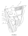
- Figure 4 illustrates a further stage of assembly of the display panel in which the first upper panel 24 has been folded about fold line 23 such that a portion of the crate C is disposed between the first inner panel 24 and the first main panel 12.
- a portion of the article B such as the article closure T (which in the illustrated embodiment is a crown cork), has been received within the article receiving aperture 40 of first article receiving panel 20.
- Figure 5 illustrates securing the second main panel 14 to the crate C by engaging the second locking mechanism 18 with the crate C.
- Crate C comprises an aperture A in a first side wall, which defines in part a carrying handle H through which a user may engage the crate C to carry the crate C.
- Second locking mechanism 18 is inserted through the aperture A as shown in Figure 5 and 6 .
- the upper and lower tabs 54, 56 engage with inner surfaces of the crate C to secure the second main panel 14 in position.
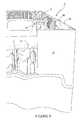
- the first locking mechanism 16 is inserted through an aperture A in a first end wall; again the aperture A may define in part a carrying handle H, as shown in Figures 7 and 8 .
- Figure 9 illustrates the crate C in which the display panel 12, 14 has been secured thereto. It can be seen that the lower end edge 66 of the first and second main panels 12, 14 mate with an upper edge of an embossment or feature 70 of the crate C.
- Figure 10 illustrates an internal view of the display panel 12, 14 in securement with the crate C.
- the crate C comprises substantially vertically orientated grooves or recesses G disposed on an inner surface of the crate C, upper tab 54 of second locking mechanism 18 and upper tab 64 of first locking mechanism 16 have been secured in a respective one of the grooves or recesses G.
- the crate C may comprise a lip or extended edge of bearing disposed about the periphery of the apertures A, in particular upper portions of the periphery of the apertures A; such lip or extended edge of bearing may provide a more comfortable carrying handle H.
- the recesses 50, 52, 60, 62 of the first and second locking mechanisms 16,18 are preferably shaped to accommodate the lip or extended edge of bearing as illustrated in Figure 10 .
- the crate C may also comprise a pillar P which may provide structural support to the crate C; in the illustrated embodiment the second inner panel 26 is shaped to accommodate the pillar P, by being provided with a cutout or recess. In alternative embodiments either or both of the first and second inner panels 24, 26 may be shaped to accommodate internal features of the crate C.
- FIG. 11 to 14 there is shown an alternative embodiment of the present invention.
- like numerals have, where possible, been used to denote like parts, albeit with the addition of the prefix "100" and so on to indicate that these features belong to the second embodiment.
- the alternative embodiments share many common features with the first embodiment and therefore only the differences from the embodiment illustrated in Figures 1 to 10 will be described in any greater detail.
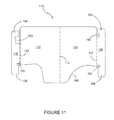
- Blank 110 comprises a first main panel 112 and a second main panel 114 hingedly connected to one another by a fold line 113.
- First main panel 112 comprises a first locking mechanism 116, the first locking mechanism 116 is hinged to a side edge of the first main panel 112 along a fold line 115.
- First locking mechanism 116 comprises upper and lower tabs 164, 158 respectively.
- the upper and lower tabs 164, 158 are separated from the first main panel 112 by a cut line, and are preferably in a spaced apart relationship with the first main panel 112.
- a recess 162 is provided in the upper tab 164 adjacent the fold line 115.
- a recess 160 is provided in the lower tab 158 adjacent the fold line 115.
- the recess 162, 160 define engaging edges in the upper and lower tabs 164, 158 for securing the first main panel 112 to a crate C.
- Second main panel 114 comprises a second locking mechanism 118, the second locking mechanism 118 is hinged to a side edge of the second main panel 114 along a fold line 117.
- Second locking mechanism 118 comprises upper and lower tabs 514, 156 respectively.
- the upper and lower tabs 154, 156 are separated from the second main panel 114 by a cut line, and are preferably in a spaced apart relationship with the second main panel 114.
- a recess 150 is provided in the upper tab 154 adjacent the fold line 117.
- a recess 152 is provided in the lower tab 156 adjacent the fold line 177.
- the recess 150, 152 define engaging edges in the upper and lower tabs 154, 156 for securing the second main panel 114 to a crate C.
- the first and second main panels 112, 114 each comprise a lower end edge 166, which edge 166 may be shaped to any desired shape, optionally the lower end edge 166 is shaped to complement a feature or embossment 70 of the crate C to which the display panel is to be attached.
- Figure 11 the first and second article engaging mechanisms E1, E2 have been omitted.
- Figure 12 illustrates the application of the display panel of the second embodiment to a crate C. It is envisaged that the method of assembly of the second embodiment will be similar to that of the first embodiment herein before described, wherein the steps of assembling the first and second article engaging mechanisms E1, E2, such as securing the first and second article engaging panels 20, 22 to an article B, will be omitted.
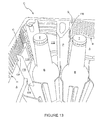
- the display panel is not secured to an article B within the crate C thereby allowing an unrestricted access to all of the articles B within the crate C.
- Figure 14 illustrates a crate C in which the display panels of both the first and second embodiments have been applied to a crate C, each of the display panels is secured to walls of the crate C.
- the fold line 13, 113 may be omitted, such that the display panel comprises only one main panel to which the first and second locking mechanisms are hingedly connected.
- the main panel may not be folded about a corner of the crate C such that it engages with a side or end wall only,
- the display panel may comprise three or more main panels hingedly connected to one another such that the display panel is secured to three or more walls of the crate C respectively.
- first and second locking mechanisms 16, 18, 116, 118 may be dimensioned and arranged so as to restrict movement of the display panel with respect to the crate C, for example preventing slipping of the display panel in a horizontal or vertical over the surface of the crate C.
- the display panel may comprise one, two or more than two locking mechanisms. Further it is envisaged that each of the provided locking mechanisms may be inserted into different apertures of the crate or into the same aperture of the crate; that is to say more than one of the locking mechanisms provided may be inserted into the same aperture of the crate, however, all the provided locking mechanisms need not be inserted into the same aperture.
- the aperture of the crate which receives the locking mechanism may or may not also be suitable for use as a carrying handle.
- hinged connection should not be construed as necessarily referring to a single fold line only; indeed it is envisaged that hinged connection can be formed from one or more of the following, a short slit, a frangible line or a fold line without departing from the scope of the invention.
Landscapes
- Engineering & Computer Science (AREA)
- Ceramic Engineering (AREA)
- Mechanical Engineering (AREA)
- Rigid Containers With Two Or More Constituent Elements (AREA)
Abstract
A package, in particular a crate (C), for holding one or more articles (B), the package comprising one or more apertures (A) disposed in one or more walls of the package, the package comprising a detachable display panel (10) comprising a main panel (12,14) and first and second locking mechanisms (16,18) each of the first and second locking mechanisms being hingedly connected to the main panel and being folded with respect to the main panel, the main panel (12,14) being disposed in face contacting relationship with an outer surface of the crate and at least a portion of each of the first and second locking mechanisms (16,18) being inserted into one, or a respective one of a pair of apertures, of the one or more apertures, each of the first and second locking mechanisms comprising at least one tab (54,56,58,68) in engagement with an inner surface of the crate.

Description
- The present invention relates to a package, crate cover and blank forming the same, more specifically, but not exclusively to an advertising panel having a locking mechanism for engaging with a crate.
- In the field of packaging it is often required to provide consumers with a package comprising multiple primary product containers, such multi-packs are desirable for shipping and distribution and for display of promotional information. For cost and environmental considerations, such cartons or carriers need to be formed from as little material as possible and cause as little wastage in the materials from which they are formed as possible. Another consideration is the strength of the packaging and its suitability for holding and transporting large weights of articles.
- It is desirable to provide a display panel or information panel which is detachable or interchangeable on a package, especially when the package may be recycled or reused. In particular it is desirable that the application and removal of display panel to and from the package does not compromise the package's integrity or appearance.
- The present invention seek to overcome or at least mitigate the problems of the prior art.
- According to a first aspect of the present invention there is provided a package, in particular a crate, for holding one or more articles, the package comprising one or more apertures disposed in one or more walls of the package, the package comprising a detachable display panel comprising a main panel and first and second locking mechanisms, each of the first and second locking mechanisms being hingedly connected to the main panel and being folded with respect to the main panel, the main panel being disposed in face contacting relationship with an outer surface of the package and at least a portion of each of the first and second locking mechanisms each being inserted into an aperture, of the one or more apertures, each of the first and second locking mechanisms comprising at least one tab in engagement with an inner surface of the package.
- Preferably, the package comprises one or more article receiving structures hingedly connected to the main panel.
- Optionally, the first and second locking mechanisms are inserted into the same aperture. More preferably, the or each article receiving structure comprises a top panel hingedly connected to an inner panel which is hingedly connected to an article receiving panel, the top panel disposed on an upper edge of the package, the inner panel disposed in face contacting relationship with an inner surface of the package, and the article receiving panel comprising an aperture into which an upper portion of an article is received.
- Optionally, the article receiving panel is disposed at an elevation below the upper edge of the package.
- Optionally, the main panel comprises one or more fold lines, the one or more fold line being aligned with a respective corner of the package.
- Preferably, the article receiving panel comprises a first series of tabs disposed about the periphery of the article receiving aperture.
- More preferably, the article receiving panel comprises a second series of tabs disposed about the article receiving aperture, wherein each tab of the second series of tabs is struck from a tab of the first series of tabs.
- Optionally, the article receiving panel engages a flange or protrusion of an article or article closure.
- According to a second aspect of the present invention there is provided a display panel for a crate comprising a main panel and first and second locking mechanisms hingedly connected thereto, each of the first and second locking mechanisms being foldable with respect to the main panel for insertion into an aperture or respective aperture disposed in a wall of the crate, the first and second locking mechanisms each comprising at least one tab for engaging an inner surface of the crate.
- According to a third aspect of the present invention there is provided a blank for forming a display panel comprising a main panel and a first locking panel and a second locking panel hingedly connected thereto each of first and second locking panels forming first and second locking mechanisms respectively, the first and second locking panels each comprising at least one tab for engaging an inner surface of the crate when each of the first and second locking mechanisms are folded and inserted into an aperture or respective aperture disposed in a wall of the crate.
- Exemplary embodiments of the invention will now be described with reference to the accompanying drawings, in which:
-
FIGURE 1 is a plan view from above of a blank for forming the display panel according to a first embodiment of the invention; -
FIGURE 2 is a perspective view from above of a crate upon which the blank ofFigure 1 may be assembled to form a display panel; -
FIGURE 3 is a perspective view from above of first stage of assembly of the blank ofFigure 1 into a display panel; -
FIGURE 4 is a perspective view from above of a second stage of assembly of the blank ofFigure 1 into a display panel; -
FIGURE 5 is a perspective view from above of third stage of assembly of the blank ofFigure 1 into a display panel; -
FIGURE 6 is a perspective view from above of fourth stage of assembly of the blank ofFigure 1 ; -
FIGURE 7 is a perspective view from above of fifth stage of assembly of the blank ofFigure 1 ; -
FIGURE 8 is an end view of an end of the crate with the display panel according to a first embodiment of the invention; -
FIGURE 9 is a perspective view from above of the crate with the display panel according to the first embodiment; -
FIGURE 10 is a perspective view from above of an internal portion of the crate with the display panel of the first embodiment; -
FIGURE 11 is a plan view from above of a blank for forming a display panel according to a second embodiment of the invention; -
FIGURE 12 is a perspective view from above of a crate with a display panel formed from the blank ofFigure 11 ; -
FIGURE 13 is a perspective view from above of an internal portion of the crate with the display panel ofFigure 12 ; -
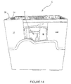
FIGURE 14 is a perspective view from above of a crate comprising the display panel formed from the blank ofFigure 1 and the display panel formed from the blank ofFigure 11 . - Detailed descriptions of specific embodiments of the package, blanks and cartons are disclosed herein. It will be understood that the disclosed embodiments are merely examples of the way in which certain aspects of the invention can be implemented and do not represent an exhaustive list of all of the ways the invention may be embodied. Indeed, it will be understood that the packages, blanks and cartons described herein may be embodied in various and alternative forms. The figures are not necessarily to scale and some features may be exaggerated or minimised to show details of particular components. Well-known components, materials or methods are not necessarily described in great detail in order to avoid obscuring the present disclosure. Any specific structural and functional details disclosed herein are not to be interpreted as limiting, but merely as a basis for the claims and as a representative basis for teaching one skilled in the art to variously employ the invention.
- Referring to
Figure 1 andFigure 2 there is shown a plan view of a blank 10 capable of forming a display panel or cover for a crate C for packaging one or more articles B such as cans or bottles. -
Blank 10 comprises a firstmain panel 12 and a secondmain panel 14 hingedly connected to one another by afold line 13. A first article engaging mechanism E1 is hinged to a first, upper, end edge of firstmain panel 12. First article engaging mechanism E1 comprises a firstarticle receiving panel 20 hingedly connected to a firstinner panel 24 along afold line 19. Firstinner panel 24 is hinged to atop panel 28 byfold line 23.Top panel 28 is hingedly connected to the firstmain panel 12 along afold line 27. - A second article engaging mechanism E2 is hinged to a first, upper, end edge of second
main panel 14. Second article engaging mechanism E2 comprises a secondarticle receiving panel 22 hingedly connected to a secondinner panel 26 along afold line 21. Firstinner panel 26 is hinged to atop panel 30 byfold line 25.Top panel 30 is hingedly connected to the main panel along afold line 29. - The first and second
article receiving panels article receiving aperture 40. A plurality ofmajor tabs 42, defined in part byradial cut lines 48, are disposed about the perimeter of each of thearticle receiving apertures 40. A plurality ofminor tabs 46 are provided about the perimeter of each of thearticle receiving apertures 40. Eachminor tab 46 is struck from a respective one of themajor tabs 42. - Each of the
major tabs 42 is substantially trapezoidal in shape. Each of theminor tabs 46 is defined in part by anarcuate cut line 44 and is substantially D-shaped. Themajor tabs 42 and theminor tabs 40 are hingedly coupled to the first or secondarticle receiving panel - First
main panel 12 comprises afirst locking mechanism 16, thefirst locking mechanism 16 is hinged to a side edge of the firstmain panel 12 along afold line 15.First locking mechanism 16 comprises upper andlower tabs lower tabs main panel 12 by a cut line, and are preferably in a spaced apart relationship with the firstmain panel 12. Arecess 62 is provided in theupper tab 64 adjacent thefold line 15. Arecess 60 is provided in thelower tab 58 adjacent thefold line 15. Therecess lower tabs main panel 12 to a crate C. - Second
main panel 14 comprises asecond locking mechanism 18, thesecond locking mechanism 18 is hinged to a side edge of the secondmain panel 14 along afold line 17.Second locking mechanism 18 comprises upper andlower tabs lower tabs main panel 14 by a cut line, and are preferably in a spaced apart relationship with the secondmain panel 14. Arecess 50 is provided in theupper tab 54 adjacent thefold line 17. Arecess 52 is provided in thelower tab 56 adjacent the fold line 77. Therecess lower tabs main panel 14 to a crate C. - The first and second
main panels lower end edge 66, which edge may be shaped to any desired shape, optionally thelower end edge 66 is shaped to complement afeature 70 of the crate C to which the display panel is to be attached. - Turning to the construction of the display panel as illustrated in
Figures 2 to 10 , it is envisaged that the display panel or cover can be formed by a series of sequential folding operations in a straight line machine so that the display panel is not required to be rotated or inverted to complete its construction. The folding process is not limited to that described below and may be altered according to particular manufacturing requirements. -
Figure 3 illustrates a stage of assembly of the display panel about a portion of the crate C. First and secondmain panels fold line 13 substantially about a corner of the crate C. Second top panel 33 has been folded aboutfold line 29 to overly an upper edge of the crate C. Secondinner panel 26 has been folded internally of the crate C such that the portion of the crate C is disposed between the secondmain panel 14 and the secondinner panel 26. -
Article receiving panel 22 has been folded to be substantially perpendicular to the secondinner panel 26. An article closure T, such as a crown cork, of an article B has been received within thearticle receiving aperture 40 of the secondarticle receiving panel 22. - The first
top panel 20 has been folded aboutfold line 21 to overly an upper edge of the crate C. -
Figure 4 illustrates a further stage of assembly of the display panel in which the firstupper panel 24 has been folded aboutfold line 23 such that a portion of the crate C is disposed between the firstinner panel 24 and the firstmain panel 12. A portion of the article B, such as the article closure T (which in the illustrated embodiment is a crown cork), has been received within thearticle receiving aperture 40 of firstarticle receiving panel 20. -
Figure 5 illustrates securing the secondmain panel 14 to the crate C by engaging thesecond locking mechanism 18 with the crate C. - Crate C comprises an aperture A in a first side wall, which defines in part a carrying handle H through which a user may engage the crate C to carry the crate C.
Second locking mechanism 18 is inserted through the aperture A as shown inFigure 5 and6 . The upper andlower tabs main panel 14 in position. Similarly thefirst locking mechanism 16 is inserted through an aperture A in a first end wall; again the aperture A may define in part a carrying handle H, as shown inFigures 7 and8 . -
Figure 9 illustrates the crate C in which thedisplay panel lower end edge 66 of the first and secondmain panels -
Figure 10 illustrates an internal view of thedisplay panel upper tab 54 ofsecond locking mechanism 18 andupper tab 64 offirst locking mechanism 16 have been secured in a respective one of the grooves or recesses G. - The crate C may comprise a lip or extended edge of bearing disposed about the periphery of the apertures A, in particular upper portions of the periphery of the apertures A; such lip or extended edge of bearing may provide a more comfortable carrying handle H.
- The
recesses second locking mechanisms Figure 10 . - The crate C may also comprise a pillar P which may provide structural support to the crate C; in the illustrated embodiment the second
inner panel 26 is shaped to accommodate the pillar P, by being provided with a cutout or recess. In alternative embodiments either or both of the first and secondinner panels - Referring now to
Figures 11 to 14 , there is shown an alternative embodiment of the present invention. In the second illustrated embodiment, like numerals have, where possible, been used to denote like parts, albeit with the addition of the prefix "100" and so on to indicate that these features belong to the second embodiment. The alternative embodiments share many common features with the first embodiment and therefore only the differences from the embodiment illustrated inFigures 1 to 10 will be described in any greater detail. -
Blank 110 comprises a firstmain panel 112 and a secondmain panel 114 hingedly connected to one another by afold line 113. - First
main panel 112 comprises afirst locking mechanism 116, thefirst locking mechanism 116 is hinged to a side edge of the firstmain panel 112 along afold line 115.First locking mechanism 116 comprises upper andlower tabs lower tabs main panel 112 by a cut line, and are preferably in a spaced apart relationship with the firstmain panel 112. Arecess 162 is provided in theupper tab 164 adjacent thefold line 115. Arecess 160 is provided in thelower tab 158 adjacent thefold line 115. Therecess lower tabs main panel 112 to a crate C. - Second
main panel 114 comprises asecond locking mechanism 118, thesecond locking mechanism 118 is hinged to a side edge of the secondmain panel 114 along afold line 117.Second locking mechanism 118 comprises upper andlower tabs 514, 156 respectively. The upper andlower tabs main panel 114 by a cut line, and are preferably in a spaced apart relationship with the secondmain panel 114. Arecess 150 is provided in theupper tab 154 adjacent thefold line 117. Arecess 152 is provided in thelower tab 156 adjacent the fold line 177. Therecess lower tabs main panel 114 to a crate C. - The first and second
main panels lower end edge 166, whichedge 166 may be shaped to any desired shape, optionally thelower end edge 166 is shaped to complement a feature orembossment 70 of the crate C to which the display panel is to be attached. - In the illustrated second embodiment of the invention shown in
Figure 11 the first and second article engaging mechanisms E1, E2 have been omitted.Figure 12 illustrates the application of the display panel of the second embodiment to a crate C. It is envisaged that the method of assembly of the second embodiment will be similar to that of the first embodiment herein before described, wherein the steps of assembling the first and second article engaging mechanisms E1, E2, such as securing the first and secondarticle engaging panels - As can be seen from
Figure 13 in the second embodiment the display panel is not secured to an article B within the crate C thereby allowing an unrestricted access to all of the articles B within the crate C. -
Figure 14 illustrates a crate C in which the display panels of both the first and second embodiments have been applied to a crate C, each of the display panels is secured to walls of the crate C. - It can be appreciated that various changes may be made within the scope of the present invention, for example, the size and shape of the panels and apertures may be adjusted to accommodate articles of differing size or shape.
- In alternative embodiments of the invention the
fold line - It will be appreciated that the first and
second locking mechanisms - It is envisaged that the display panel may comprise one, two or more than two locking mechanisms. Further it is envisaged that each of the provided locking mechanisms may be inserted into different apertures of the crate or into the same aperture of the crate; that is to say more than one of the locking mechanisms provided may be inserted into the same aperture of the crate, however, all the provided locking mechanisms need not be inserted into the same aperture. The aperture of the crate which receives the locking mechanism may or may not also be suitable for use as a carrying handle.
- It will be recognised that as used herein, directional references such as "top", "bottom", "front", "back", "end", "side", "inner", "outer", "upper" and "lower" do not limit the respective panels to such orientation, but merely serve to distinguish these panels from one another. Any reference to hinged connection should not be construed as necessarily referring to a single fold line only; indeed it is envisaged that hinged connection can be formed from one or more of the following, a short slit, a frangible line or a fold line without departing from the scope of the invention.
Claims (11)
- A package comprising a crate for holding one or more articles, the crate comprising one or more apertures disposed in one or more walls of the crate, the package further comprising a detachable display panel comprising a main panel and first and second locking mechanisms each being hingedly connected to the main panel and being folded with respect to the main panel, the main panel being disposed in face contacting relationship with an outer surface of the crate, at least a portion of each of the first and second locking mechanisms each being inserted into an aperture of the one or more apertures, each of the first and second locking mechanisms comprising at least one tab in engagement with an inner surface of the crate.
- A package according to claim 1 comprising one or more article receiving structures hingedly connected to the main panel.
- A package according to either one of claims 1 or 2 wherein the first and second locking mechanisms are inserted into the same aperture.
- A package according to either one of claims 2 or 3 wherein the or each article receiving structure comprises top panel hingedly connected to an inner panel which is hingedly connected to an article receiving panel, the top panel disposed on an upper edge of the crate, the inner panel disposed in face contacting relationship with an inner surface of the crate, and the article receiving panel comprising an aperture into which an upper portion of an article is received.
- A package according to claim 4 wherein the article receiving panel is disposed at an elevation below the upper edge of the crate.
- A package according to any one of claims 1 to 5 wherein the main panel comprises one or more fold lines, the one or more fold lines being aligned with a respective corner of the package.
- A package according to claim 4 wherein the article receiving panel comprises first series of tabs disposed about the periphery of the article receiving aperture.
- A package according to claim 7 wherein the article receiving panel comprises comprising a second series of tabs disposed about the article receiving aperture, wherein each tab of the second series of tabs is struck from a tab of the first series of tabs.
- A package according to any one of claims 4 to 7 wherein the article receiving panel engages a flange or protrusion of an article or article closure.
- A display panel for a crate comprising a main panel and first and second locking mechanisms hingedly connected thereto, each of the first and second locking mechanisms being foldable with respect to the main panel for insertion into an aperture or respective aperture disposed in a wall of the crate, the first and second locking mechanisms each comprising at least one tab for engaging an inner surface of the crate.
- A blank for forming a display panel comprising a main panel and a first locking panel and a second locking panel hingedly connected thereto each of first and second locking panels forming first and second locking mechanisms respectively, the first and second locking panels each comprising at least one tab for engaging an inner surface of a crate when each of the first and second locking mechanisms are folded and inserted into an aperture or respective aperture disposed in a wall of the crate.
Applications Claiming Priority (1)
| Application Number | Priority Date | Filing Date | Title |
|---|---|---|---|
| GB201112221A GB201112221D0 (en) | 2011-07-15 | 2011-07-15 | Crate cover and blank |
Publications (1)
| Publication Number | Publication Date |
|---|---|
| EP2546156A1 true EP2546156A1 (en) | 2013-01-16 |
Family
ID=44586689
Family Applications (1)
| Application Number | Title | Priority Date | Filing Date |
|---|---|---|---|
| EP12175896A Withdrawn EP2546156A1 (en) | 2011-07-15 | 2012-07-11 | Crate cover and blank |
Country Status (2)
| Country | Link |
|---|---|
| EP (1) | EP2546156A1 (en) |
| GB (1) | GB201112221D0 (en) |
Cited By (1)
| Publication number | Priority date | Publication date | Assignee | Title |
|---|---|---|---|---|
| DE202024001108U1 (en) * | 2024-06-07 | 2025-09-12 | Offset Company Display Gmbh | Box plug with folding wing |
Citations (5)
| Publication number | Priority date | Publication date | Assignee | Title |
|---|---|---|---|---|
| FR2491035A1 (en) * | 1980-05-15 | 1982-04-02 | Mead Corp | ARTICLE HOLDER WITH PROTECTIVE PACKAGE |
| DE20000305U1 (en) * | 2000-01-08 | 2000-04-27 | P.O.S.-Partner Schaudinn GmbH, 42281 Wuppertal | Universal poster holder |
| EP1674401A1 (en) * | 2004-12-27 | 2006-06-28 | PEPSICO DEUTSCHLAND GmbH | Method for adding advertising matter to trays and corresponding trays |
| DE102006045475A1 (en) * | 2006-09-22 | 2008-05-08 | Nils Heise | Insert for e.g. beer crate, is inserted into opened side of bottle case, where special latches are attached at sides for preventing falling of insert and insert is printed with advertisement |
| EP2143647A1 (en) * | 2008-07-08 | 2010-01-13 | Schoeller Arca Systems GmbH | Plastic box with a relief and method for manufacturing the box |
-
2011
- 2011-07-15 GB GB201112221A patent/GB201112221D0/en not_active Ceased
-
2012
- 2012-07-11 EP EP12175896A patent/EP2546156A1/en not_active Withdrawn
Patent Citations (5)
| Publication number | Priority date | Publication date | Assignee | Title |
|---|---|---|---|---|
| FR2491035A1 (en) * | 1980-05-15 | 1982-04-02 | Mead Corp | ARTICLE HOLDER WITH PROTECTIVE PACKAGE |
| DE20000305U1 (en) * | 2000-01-08 | 2000-04-27 | P.O.S.-Partner Schaudinn GmbH, 42281 Wuppertal | Universal poster holder |
| EP1674401A1 (en) * | 2004-12-27 | 2006-06-28 | PEPSICO DEUTSCHLAND GmbH | Method for adding advertising matter to trays and corresponding trays |
| DE102006045475A1 (en) * | 2006-09-22 | 2008-05-08 | Nils Heise | Insert for e.g. beer crate, is inserted into opened side of bottle case, where special latches are attached at sides for preventing falling of insert and insert is printed with advertisement |
| EP2143647A1 (en) * | 2008-07-08 | 2010-01-13 | Schoeller Arca Systems GmbH | Plastic box with a relief and method for manufacturing the box |
Cited By (1)
| Publication number | Priority date | Publication date | Assignee | Title |
|---|---|---|---|---|
| DE202024001108U1 (en) * | 2024-06-07 | 2025-09-12 | Offset Company Display Gmbh | Box plug with folding wing |
Also Published As
| Publication number | Publication date |
|---|---|
| GB201112221D0 (en) | 2011-08-31 |
Similar Documents
| Publication | Publication Date | Title |
|---|---|---|
| EP3245138B1 (en) | Carton and blank therefor | |
| US10106290B2 (en) | Carton, blank, and method of folding | |
| EP2768744B1 (en) | Fastening mechanism for a carton, carton incorporating the same and blank for forming the carton | |
| US10173804B2 (en) | Carrier and blank therefor | |
| US9493268B2 (en) | Package with strap handle | |
| AU2014260121B2 (en) | Carton and carton blank | |
| US11932472B2 (en) | Carton and blank therefor | |
| AU2025200033A1 (en) | Carton and blank therefor | |
| JP2014513654A (en) | Container package | |
| US20240059467A1 (en) | Article carriers and blanks therefor | |
| US11891226B2 (en) | Basket style carrier, shipping carton and package system | |
| US20210198021A1 (en) | Carton and blank therefor | |
| US20230040097A1 (en) | Article carrier and blank therefor | |
| US20200339330A1 (en) | Article carrier, shipping carton & package system | |
| US20180346181A1 (en) | Carton and carton blank | |
| US10279951B2 (en) | Carton and carton blank | |
| US20220297911A1 (en) | Article carrier and blank therfor | |
| US11827436B2 (en) | Carton and blank therefor | |
| US20160039586A1 (en) | Package with handle, blank therefor and part-formed structure | |
| JP2016204039A (en) | Carton and blank therefor | |
| JP5572667B2 (en) | Carton and carton blank | |
| WO2012149538A1 (en) | Carton, carton blank and package | |
| HK1246258B (en) | Carton and blank therefor |
Legal Events
| Date | Code | Title | Description |
|---|---|---|---|
| PUAI | Public reference made under article 153(3) epc to a published international application that has entered the european phase |
Free format text: ORIGINAL CODE: 0009012 |
|
| 17P | Request for examination filed |
Effective date: 20120711 |
|
| AK | Designated contracting states |
Kind code of ref document: A1 Designated state(s): AL AT BE BG CH CY CZ DE DK EE ES FI FR GB GR HR HU IE IS IT LI LT LU LV MC MK MT NL NO PL PT RO RS SE SI SK SM TR |
|
| AX | Request for extension of the european patent |
Extension state: BA ME |
|
| STAA | Information on the status of an ep patent application or granted ep patent |
Free format text: STATUS: THE APPLICATION IS DEEMED TO BE WITHDRAWN |
|
| 18D | Application deemed to be withdrawn |
Effective date: 20150203 |