EP2545993A1 - Pipette member and cell isolation instrument - Google Patents
Pipette member and cell isolation instrument Download PDFInfo
- Publication number
- EP2545993A1 EP2545993A1 EP12175545A EP12175545A EP2545993A1 EP 2545993 A1 EP2545993 A1 EP 2545993A1 EP 12175545 A EP12175545 A EP 12175545A EP 12175545 A EP12175545 A EP 12175545A EP 2545993 A1 EP2545993 A1 EP 2545993A1
- Authority
- EP
- European Patent Office
- Prior art keywords
- opening
- cell isolation
- pipette
- container
- tissue
- Prior art date
- Legal status (The legal status is an assumption and is not a legal conclusion. Google has not performed a legal analysis and makes no representation as to the accuracy of the status listed.)
- Granted
Links
Images



Classifications
-
- C—CHEMISTRY; METALLURGY
- C12—BIOCHEMISTRY; BEER; SPIRITS; WINE; VINEGAR; MICROBIOLOGY; ENZYMOLOGY; MUTATION OR GENETIC ENGINEERING
- C12M—APPARATUS FOR ENZYMOLOGY OR MICROBIOLOGY; APPARATUS FOR CULTURING MICROORGANISMS FOR PRODUCING BIOMASS, FOR GROWING CELLS OR FOR OBTAINING FERMENTATION OR METABOLIC PRODUCTS, i.e. BIOREACTORS OR FERMENTERS
- C12M47/00—Means for after-treatment of the produced biomass or of the fermentation or metabolic products, e.g. storage of biomass
- C12M47/04—Cell isolation or sorting
-
- B—PERFORMING OPERATIONS; TRANSPORTING
- B01—PHYSICAL OR CHEMICAL PROCESSES OR APPARATUS IN GENERAL
- B01L—CHEMICAL OR PHYSICAL LABORATORY APPARATUS FOR GENERAL USE
- B01L3/00—Containers or dishes for laboratory use, e.g. laboratory glassware; Droppers
- B01L3/02—Burettes; Pipettes
- B01L3/021—Pipettes, i.e. with only one conduit for withdrawing and redistributing liquids
-
- B—PERFORMING OPERATIONS; TRANSPORTING
- B01—PHYSICAL OR CHEMICAL PROCESSES OR APPARATUS IN GENERAL
- B01L—CHEMICAL OR PHYSICAL LABORATORY APPARATUS FOR GENERAL USE
- B01L3/00—Containers or dishes for laboratory use, e.g. laboratory glassware; Droppers
- B01L3/50—Containers for the purpose of retaining a material to be analysed, e.g. test tubes
- B01L3/502—Containers for the purpose of retaining a material to be analysed, e.g. test tubes with fluid transport, e.g. in multi-compartment structures
-
- C—CHEMISTRY; METALLURGY
- C12—BIOCHEMISTRY; BEER; SPIRITS; WINE; VINEGAR; MICROBIOLOGY; ENZYMOLOGY; MUTATION OR GENETIC ENGINEERING
- C12M—APPARATUS FOR ENZYMOLOGY OR MICROBIOLOGY; APPARATUS FOR CULTURING MICROORGANISMS FOR PRODUCING BIOMASS, FOR GROWING CELLS OR FOR OBTAINING FERMENTATION OR METABOLIC PRODUCTS, i.e. BIOREACTORS OR FERMENTERS
- C12M45/00—Means for pre-treatment of biological substances
- C12M45/02—Means for pre-treatment of biological substances by mechanical forces; Stirring; Trituration; Comminuting
-
- B—PERFORMING OPERATIONS; TRANSPORTING
- B01—PHYSICAL OR CHEMICAL PROCESSES OR APPARATUS IN GENERAL
- B01L—CHEMICAL OR PHYSICAL LABORATORY APPARATUS FOR GENERAL USE
- B01L2300/00—Additional constructional details
- B01L2300/04—Closures and closing means
- B01L2300/046—Function or devices integrated in the closure
- B01L2300/047—Additional chamber, reservoir
-
- B—PERFORMING OPERATIONS; TRANSPORTING
- B01—PHYSICAL OR CHEMICAL PROCESSES OR APPARATUS IN GENERAL
- B01L—CHEMICAL OR PHYSICAL LABORATORY APPARATUS FOR GENERAL USE
- B01L2300/00—Additional constructional details
- B01L2300/06—Auxiliary integrated devices, integrated components
- B01L2300/0681—Filter
-
- B—PERFORMING OPERATIONS; TRANSPORTING
- B01—PHYSICAL OR CHEMICAL PROCESSES OR APPARATUS IN GENERAL
- B01L—CHEMICAL OR PHYSICAL LABORATORY APPARATUS FOR GENERAL USE
- B01L2400/00—Moving or stopping fluids
- B01L2400/04—Moving fluids with specific forces or mechanical means
- B01L2400/0475—Moving fluids with specific forces or mechanical means specific mechanical means and fluid pressure
- B01L2400/0487—Moving fluids with specific forces or mechanical means specific mechanical means and fluid pressure fluid pressure, pneumatics
-
- G—PHYSICS
- G01—MEASURING; TESTING
- G01N—INVESTIGATING OR ANALYSING MATERIALS BY DETERMINING THEIR CHEMICAL OR PHYSICAL PROPERTIES
- G01N35/00—Automatic analysis not limited to methods or materials provided for in any single one of groups G01N1/00 - G01N33/00; Handling materials therefor
- G01N35/10—Devices for transferring samples or any liquids to, in, or from, the analysis apparatus, e.g. suction devices, injection devices
- G01N2035/1027—General features of the devices
- G01N2035/103—General features of the devices using disposable tips
-
- G—PHYSICS
- G01—MEASURING; TESTING
- G01N—INVESTIGATING OR ANALYSING MATERIALS BY DETERMINING THEIR CHEMICAL OR PHYSICAL PROPERTIES
- G01N35/00—Automatic analysis not limited to methods or materials provided for in any single one of groups G01N1/00 - G01N33/00; Handling materials therefor
- G01N35/10—Devices for transferring samples or any liquids to, in, or from, the analysis apparatus, e.g. suction devices, injection devices
- G01N2035/1027—General features of the devices
- G01N2035/1048—General features of the devices using the transfer device for another function
- G01N2035/1053—General features of the devices using the transfer device for another function for separating part of the liquid, e.g. filters, extraction phase
Definitions
- the present invention relates to a cell isolation instrument which can be used in the case where a pathological analysis is performed.
- a pathological analysis on a tissue slice is performed by a cytotechnologist or a pathologist.
- a pathological analysis on a tissue slice is performed by a cytotechnologist or a pathologist.
- the mincing process with using a blade is required.
- a suspension which is obtained after the mincing process must be filtered through a filter.
- two steps of operation are required.
- a skilled technique is required for preparing a specimen or performing a diagnosis by a cytotechnologist or a pathologist, and there is a possibility that a difference may be produced in the diagnosis result depending on the difference in technique.
- procedures such as tissue fixation, section preparation, and staining are necessary, and a cytotechnologist or the like is restrained for a predetermined time period. Therefore, procedures which are to be performed before diagnosis are requested to be automatized.
- Japanese Patent No. 4156847 discloses a device for mincing a tissue required for culturing cells.
- the device includes a cylinder member in which a metal mesh is disposed in each of upper and lower openings. A tissue piece is placed on the metal mesh, and a centrifugal separation process is performed on the cylinder member, whereby the tissue is minced.
- the mincing process can be automatically performed, but procedures such as section preparation and staining cannot be automatized. Moreover, it is not considered that a cell suspension containing isolated cells is automatically recovered.
- a pipette member to be attachable to a container capable of accommodating a tissue and a liquid, the pipette member used for isolating cells from the tissue by stirring, the pipette member comprising: a cylinder member which includes a first opening that is to be accommodated in the container, and a second opening that is to be connected to a cell isolation apparatus, and in which a passage for communicating the first opening with the second opening is defined; and a filter member which is disposed inside the cylinder member, and which separates the passage into a first part that includes the first opening, and a second part that includes the second opening.
- a position of the filter member may be determined so that a first suction force which is applied for the stirring by the cell isolation apparatus causes only air to pass through the filter member, and, in a case where a second suction force which is larger than the first suction force is applied by the cell isolation apparatus, the liquid containing the isolated cells passes through the filter member.
- the pipette member may further comprise a lid member which defines a part of the second opening. At least a part of the filter member may be in contact with the lid member.
- the first opening may be smaller in diameter than the second opening.
- a slit which communicates with the passage is formed in a vicinity of the first opening of the cylinder member.
- a placement member on which the tissue can be placed may be provided in a vicinity of the first opening of the cylinder member.
- the first opening may be placed in a position which is deviated from a central axis of the container.
- the filter member may allow a material which is smaller than isolated cells, to pass through.
- a cell isolation instrument comprising: a container capable of accommodating a tissue and a liquid; and a pipette member attached to the container, and used for isolating cells from the tissue by stirring, the pipette member comprising: a cylinder member which includes a first opening that is accommodated in the container, and a second opening that is to be connected to a cell isolation apparatus, and in which a passage for communicating the first opening with the second opening is defined; and a filter member which is disposed inside the cylinder member, and which separates the passage into a first part that includes the first opening, and a second part that includes the second opening.
- a position of the filter member may be determined so that a first suction force which is applied for the stirring by the cell isolation apparatus causes only air to pass through the filter member, and, in a case where a second suction force which is larger than the first suction force is applied by the cell isolation apparatus, the liquid containing the isolated cells passes through the filter member.
- the first opening may be placed in a position which is deviated from a central axis of the container.
- a central axis of the container may be inclined with respect to a vertical direction.
- a dried reagent may be placed in a bottom portion of the container.
- Fig. 1 shows a state where a cell isolation instrument of an embodiment of the invention is disassembled
- Fig. 2 shows a state where the device is assembled.
- the cell isolation instrument includes a pipette member 10 and a container 20.
- the both components are formed by a resin material or the like which is noncytotoxic.
- the pipette member 10 includes a body 11, a filter 12 (filter member), and a lid member 13.
- the body 11 is a hollow cylindrical member in which a tip end portion 11a has a tapered shape.
- An opening 11b (first opening) is formed in the tip end (lower end) of the body 11, and an opening 11d is formed in the upper end surface 11c.
- the openings 11b, 11d communicate with each other through a passage 14 which is formed inside the body 11.
- a holding member 15 is disposed in an upper end portion of the body 11.
- the holding member 15 has a large-diameter portion 15a and a small-diameter portion 15b.
- a step 15c is defined in the interface between the large-diameter portion 15a and the small-diameter portion 15b.
- the large-diameter portion 15a includes the upper end surface 11c. The role of the holding member 15 will be described later.
- the lid member 13 is a cylindrical member having a large-diameter portion 13a and a small-diameter portion 13b.
- a step 13c is defined in the interface between the large-diameter portion 13a and the small-diameter portion 13b.
- An opening 13d (second opening) is formed in the upper end surface including the large-diameter portion 13a, and an opening 13e is formed in the lower end surface including the small-diameter portion 13b.
- the openings 13d, 13e communicate with each other through a passage 16 which is formed inside the lid member 13.
- the filter 12 is formed by a material which is noncytotoxic, and has mesh openings which allow a liquid containing isolated cells (cells in which nuclei are isolated) to pass therethrough.
- a nylon mesh having mesh openings of 50 ⁇ m is used as the filter 12, and adhered or welded to the lid member 13 so as to cover the opening 13e.
- the filter 12 and the small-diameter portion 13b of the lid member 13 are inserted into the opening 11d to be attached to the body 11, so that the body 11 and the lid member 13 constitute the cylinder member in the invention.
- the step 13c of the lid member 13 is adhered or welded to the upper end surface 11c of the body 11.
- the passage 14 (first part) of the body 11 and the passage 16 (second part) of the lid member 13 communicate with each other through the filter 12 which is placed in a predetermined position.
- predetermined position will be described later.
- the container 20 is a cylindrical member which has an opening 20b in the upper end surface 20a, and in which a lower end portion is configured as a round bottom.
- the container 20 is transparent so that the hollow internal space 20c is visible.
- the internal space 20c communicates with the opening 20b.
- a reagent 21 containing a surfactant, an RNA (ribonucleic acid) remover, and a fluorescent dye/pigment is accommodated on the bottom of the internal space 20c in a state where the reagent 21 is dried or freeze-dried.
- the reagent 21 dissolves in the cell treatment solution 31.
- a solution in which the osmotic pressure is equal to that of a living body, such as PBS (phosphate buffer solution) is used as the cell treatment solution 31.
- nuclei isolation of tissue cells by the surfactant RNA removal by the RNA remover, and staining of isolated DNA cell nuclei by the fluorescent dye/pigment can be performed.
- RNA removal by the RNA remover RNA removal by the RNA remover
- staining of isolated DNA cell nuclei by the fluorescent dye/pigment can be performed. This enables that, after recovery by a cell isolation apparatus which will be described later, measurement by a fluorescent analyzer (flow cytometer) or the like is performed. Therefore, rapid diagnosis can be realized.
- a fluorescent analyzer flow cytometer
- the pipette member 10 is attached to the container 20 in which the tissue 30 and the cell treatment solution 31 are accommodated in the internal space 20c. Specifically, the body 11 of the pipette member 10 is inserted from the opening 20b of the container 20 into the internal space 20c until the upper end surface 20a of the container 20 abuts against the step 15c of the holding member 15. In this state, the outer circumferential surface of the small-diameter portion 15b of the holding member 15 abuts against the inner surface of the container 20.
- the holding member 15 is fitted to an upper end portion of the container 20, so that a tip end portion 10a of the pipette member 10 is placed in a predetermined position in the internal space 20c of the container 20.
- the tip end (opening 11b) of the body 11 is placed on the central axis C1 (see Fig. 1 ) of the container 20, and opposed to the bottom of the internal space 20c via a constant gap.
- the loaded tissue 30 is placed between the tip end of the body 11 and the bottom of the internal space 20c.
- the tip end portion 11a of the body 11 is immersed in the loaded cell treatment solution 31.
- an upper end portion of the cell isolation instrument which is assembled as shown in Fig. 2 is attached to a lower end portion of a nozzle 40 of the cell isolation apparatus.
- a passage 41 of the nozzle 40 and the passage 16 of the lid member 13 communicate with each other in an air-tight and liquid-tight manner through an adequate engagement structure.
- the cell isolation apparatus includes a pump mechanism which is connected to the nozzle 40.
- the cell isolation apparatus is configured so that a controller controls the pump mechanism based on stirring conditions (stirring intensity, repetition number, duration, and the like) which are set by the user, and a pressurized state and a depressurized state can be made.
- stirring conditions stirring intensity, repetition number, duration, and the like
- the tissue 30 and the cell treatment solution 31 (containing the reagent 21) in the container 20 can be stirred by the pipette member 10 connected to the nozzle 40.
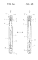
- Fig. 3A shows a state where the cell isolation apparatus makes the depressurized state.
- a predetermined suction force (first suction force) acts on the pipette member 10, and the cell treatment solution 31 in the container 20 is sucked up into the pipette member 10.
- Part of the cell treatment solution 31 is raised in the passage 14, and the tissue 30 is sucked to the tip end (opening 11b) of the pipette member 10.
- part of the tissue is smashed by collision with the tip end of the pipette member 10.
- Fig. 3B shows a state where the cell isolation apparatus makes the pressurized state.
- a predetermined pressure is applied to the pipette member 10, and the cell treatment solution 31 in the passage 41 is ejected from the opening 11b to be returned to the internal space 20c of the container 20.
- the tissue which is sucked to the opening 11b is returned into the cell treatment solution 31 while part of the tissue is smashed by shock caused by the ejection.
- the tissue 30 is gradually finely smashed to enter a minced state.
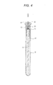
- a suspension 32 (see Fig. 4 ) containing isolated cells can be obtained.
- the isolated cells are used in a pathological analysis. In addition to the isolated cells, however, unwanted minced tissue pieces are suspended in the suspension 32. In order to use only the isolated cells in the analysis, a step of filtering out tissue pieces which are larger than the isolated cells is necessary.
- a suction force (second suction force) which is larger than that acting in the stirring process is caused by the cell isolation apparatus to act on the pipette member 10.
- the suspension 32 in the container 20 is sucked into the pipette member 10, and raised in the passage 14.
- the cell isolation apparatus continues the suction, the suspension 32 reaches the filter 12 which separates the passage 14 from the passage 16.
- the suspension 32 passes through the filter 12, unwanted tissue pieces are filtered out, and a cell suspension 33 containing desired isolated cells is obtained in the passage 16.
- the cell suspension 33 is recovered to the cell isolation apparatus, and then used in an analyzing process such as a fluorescence analysis by using a flow cytometer.
- the cell isolation process by stirring, and the process of recovering the isolated cells by filtering the suspension can be performed while the same cell isolation instrument is connected to the nozzle 40 of the cell isolation apparatus.
- the working efficiency can be largely improved as compared with a related-art process in which such a suspension is transferred to another container, and filtration is then performed.
- the process of recovering the isolated cells by filtration can be automatized.
- the pipette member 10 of the embodiment has the simple configuration where the filter 12 and the lid member 13 are attached to the body 11.
- the above-described effects can be achieved at low component and production costs.
- the pipette member 10 can be discarded in a state where the filter 12 and the lid member 13 are attached to the body 11, and it is possible to prevent the user from directly contacting with the suspension. Furthermore, it is possible to prevent foreign substances from entering in the suspension. Therefore, the safety is high.
- the two kinds of suction forces for stirring and filtration act on the pipette member 10.
- the position of the filter 12 is determined so that the liquid which enters the passage 14 is not caused to reach the filter 12 by the suction force for stirring, and caused to pass through the filter 12, only by the suction force for filtration.
- the suction force applied during stirring causes only air to pass through the filter 12, and the liquid passes through the filter 12 in the case where a suction force which is larger than that during stirring is applied as shown in Fig. 4 .
- the suction force applied during stirring causes only air to pass through the filter 12, and the liquid passes through the filter 12 in the case where a suction force which is larger than that during stirring is applied as shown in Fig. 4 .
- the process of recovering the isolated cells by filtration can be easily automatized.
- the filter 12 is not immersed in the liquid, only air passes through the filter 12, and hence the stirring resistance can be reduced as far as possible. Therefore, the load which is applied to the pump mechanism of the cell isolation apparatus during the stirring operation can be suppressed to minimum.
- the filter 12 since the filter 12 allows a material which is smaller than the isolated cells, to pass through, it is possible to collect only cells which have undergone necessary nuclei isolation. Therefore, the cell isolation process can be performed accurately and smoothly.
- the reagent 21 which is dried is placed in a bottom portion of the container 20 (the bottom of the internal space 20c), when the tissue 30 and the cell treatment solution 31 (liquid) is accommodated in the container 20, the reagent 21 dissolves in the liquid, and a process which is the object of the reagent 21 can be performed in parallel with the cell isolation process by stirring.
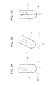
- a configuration may be employed where, as shown in Fig. 5A , a slit 17 is formed in the vicinity of the opening 11b in the tip end of the pipette member 10.
- the opening 11 is sometimes completely blocked by the tissue 30 sucked to the pipette member 10. According the configuration of the modification, even in such a case, the cell treatment solution 31 flows through the slit 17, and therefore a desired suction process can be performed. Furthermore, the load which is applied to the pump mechanism of the cell isolation apparatus that generates the suction force can be reduced.
- the position and shape of the slit 17 are not particularly limited as far as the slit is formed in the vicinity of the opening 11b and does not impede the flow of the cell treatment solution 31.
- the slit may be continuous to the opening 11b as shown in Fig. 5A , or independent from the opening 11b as shown in Fig. 5B . Namely, it is requested that the pipette member has a portion through which a liquid can pass, in addition to the opening 11b.
- a configuration may be employed where, as shown in Fig. 5C , ear-like placement members 18 are formed in the vicinity of the opening 11b in the tip end of the pipette member 10.
- the tissue 30 when the pipette member 10 is attached to the container 20 in a state where the tissue 30 is scooped by the tip end of the pipette member 10 and then placed on the placement members 18, the tissue 30 can be disposed in a predetermined position of a bottom portion of the internal space 20c without difficulty. Therefore, the stirring process can be smoothly performed.
- the shape and size of the placement members 18 may be adequately determined in accordance with the tissue 30 to be handled.
- a configuration may be employed where, as shown in Fig. 6A , in a state where the pipette member 10 is attached to the container 20, the opening 11b in the tip end of the pipette member 10 is placed in a position which is deviated from the central axis C1 of the container 20.
- a configuration may be employed where the central axis C2 of the opening 11b is inclined with respect to the central axis C1 of the container 20.
- the tip end portion 11a of the body 11 in the pipette member 10 may have a bent shape, or the shape of the holding member 15 may be made asymmetric about the central axis C1, so that the tip end portion 11a has an inclined posture.
- a configuration may be employed where, as shown in Fig. 6B , the central axis C1 of the container 20 is inclined with respect to the vertical direction V in a state where the cell isolation instrument is connected to the cell isolation apparatus.
- an adequate configuration may be employed.
- a bent portion may be disposed in the lid member 13 which is connected to the nozzle 40 of the cell isolation apparatus, and the body 11 and the container 20 may have a posture which is inclined with respect to the vertical direction V.
- a further configuration may be employed where, as shown in Fig. 6C , the central axis C1 of the container 20 and the central axis C2 of the opening 11b are in a parallel and non-coaxial relationship.
- the lid member 13 is not always essential.
- a configuration may be employed where the body 11 includes, in the side of the basal end, an opening which is to be connected to the nozzle 40 of the cell isolation apparatus, and the passage 14 of the body 11 is partitioned by the filter 12 into a part for stirring (first part) and a part for recovering the cell suspension (second part).
- the filter 12 is adhered or welded to an adequate position of the passage 14. If possible, the filter may be molded integrally with the body 11.
- the pipette member 10 is configured so as to include the body 11 and the lid member 13, however, the filter 12 is easily disposed in a predetermined position, and therefore the assembly workability is improved.
- the filter 12 is adhered or welded to the lid member 13 so as to cover the opening 13e.
- a configuration may be employed where the filter 12 which is larger in diameter than the small-diameter portion 13b of the lid member 13 is fixed to a predetermined position by sandwiching the filter between the inner surface of the opening 11d of the body 11 and the outer surface of the small-diameter portion 13b of the lid member 13.
- the tip end portion 11a of the body 11 is not always required to have a tapered shape.
- the size of the opening 11b of the body 11 can be appropriately determined. When, as in the embodiment, the size of the opening 11b of the body 11 is set so as to be smaller than the opening 13d of the lid member 13, however, it is possible to obtain a strong liquid flow during the stirring process.
Landscapes
- Health & Medical Sciences (AREA)
- Chemical & Material Sciences (AREA)
- Life Sciences & Earth Sciences (AREA)
- Engineering & Computer Science (AREA)
- Organic Chemistry (AREA)
- Zoology (AREA)
- Wood Science & Technology (AREA)
- Bioinformatics & Cheminformatics (AREA)
- General Health & Medical Sciences (AREA)
- Biotechnology (AREA)
- Chemical Kinetics & Catalysis (AREA)
- Genetics & Genomics (AREA)
- Molecular Biology (AREA)
- Biomedical Technology (AREA)
- Microbiology (AREA)
- Sustainable Development (AREA)
- Clinical Laboratory Science (AREA)
- General Engineering & Computer Science (AREA)
- Biochemistry (AREA)
- Hematology (AREA)
- Cell Biology (AREA)
- Analytical Chemistry (AREA)
- Mechanical Engineering (AREA)
- Apparatus Associated With Microorganisms And Enzymes (AREA)
- Sampling And Sample Adjustment (AREA)
- Investigating Or Analysing Biological Materials (AREA)
Abstract
Description
- The present invention relates to a cell isolation instrument which can be used in the case where a pathological analysis is performed.
- After a pathological specimen is prepared, a pathological analysis on a tissue slice is performed by a cytotechnologist or a pathologist. When cells are to be isolated from a tissue, the mincing process with using a blade is required. In order to obtain cell suspension containing isolated cells, moreover, a suspension which is obtained after the mincing process must be filtered through a filter. In order to obtain a cell suspension which is to be used in a pathological analysis, as described above, two steps of operation are required.
- A skilled technique is required for preparing a specimen or performing a diagnosis by a cytotechnologist or a pathologist, and there is a possibility that a difference may be produced in the diagnosis result depending on the difference in technique. In the period from extraction of a tissue to diagnosis, procedures such as tissue fixation, section preparation, and staining are necessary, and a cytotechnologist or the like is restrained for a predetermined time period. Therefore, procedures which are to be performed before diagnosis are requested to be automatized.
- Japanese Patent No.
4156847 - According to the technique disclosed in Japanese Patent No.
4156847 - It is therefore an object of the invention to provide at a low cost a cell isolation instrument which can efficiently recovery cells isolated from a tissue (living tissue).
- In order to achieve the object, according to the invention, there is provided a pipette member to be attachable to a container capable of accommodating a tissue and a liquid, the pipette member used for isolating cells from the tissue by stirring, the pipette member comprising: a cylinder member which includes a first opening that is to be accommodated in the container, and a second opening that is to be connected to a cell isolation apparatus, and in which a passage for communicating the first opening with the second opening is defined; and a filter member which is disposed inside the cylinder member, and which separates the passage into a first part that includes the first opening, and a second part that includes the second opening.
- A position of the filter member may be determined so that a first suction force which is applied for the stirring by the cell isolation apparatus causes only air to pass through the filter member, and, in a case where a second suction force which is larger than the first suction force is applied by the cell isolation apparatus, the liquid containing the isolated cells passes through the filter member.
- The pipette member may further comprise a lid member which defines a part of the second opening. At least a part of the filter member may be in contact with the lid member.
- The first opening may be smaller in diameter than the second opening.
- A slit which communicates with the passage is formed in a vicinity of the first opening of the cylinder member.
- A placement member on which the tissue can be placed may be provided in a vicinity of the first opening of the cylinder member.
- In a state where the pipette member is attached to the container, the first opening may be placed in a position which is deviated from a central axis of the container.
- The filter member may allow a material which is smaller than isolated cells, to pass through.
- In order to achieve the object, according to the invention, there is also provided a cell isolation instrument comprising: a container capable of accommodating a tissue and a liquid; and a pipette member attached to the container, and used for isolating cells from the tissue by stirring, the pipette member comprising: a cylinder member which includes a first opening that is accommodated in the container, and a second opening that is to be connected to a cell isolation apparatus, and in which a passage for communicating the first opening with the second opening is defined; and a filter member which is disposed inside the cylinder member, and which separates the passage into a first part that includes the first opening, and a second part that includes the second opening.
- A position of the filter member may be determined so that a first suction force which is applied for the stirring by the cell isolation apparatus causes only air to pass through the filter member, and, in a case where a second suction force which is larger than the first suction force is applied by the cell isolation apparatus, the liquid containing the isolated cells passes through the filter member.
- The first opening may be placed in a position which is deviated from a central axis of the container.
- In a state where the cell isolation instrument is attached to the cell isolation apparatus, a central axis of the container may be inclined with respect to a vertical direction.
- A dried reagent may be placed in a bottom portion of the container.
-
-
Fig. 1 is an exploded perspective view showing a cell isolation instrument of an embodiment of the invention. -
Fig. 2 is a longitudinal sectional view showing a state where the cell isolation instrument ofFig. 1 is assembled. -
Figs. 3A and 3B are longitudinal sectional views showing states where a stirring process is performed by using the cell isolation instrument ofFig. 1 . -
Fig. 4 is a longitudinal sectional view showing a state where a filtered cell suspension is recovered by using the cell isolation instrument ofFig. 1 . -
Figs. 5A, 5B and 5C are partial enlarged views showing modifications of the cell isolation instrument ofFig. 1 . -
Figs. 6A, 6B and 6C are partial enlarged views showing modifications of the cell isolation instrument ofFig. 1 . - Hereinafter, an embodiment of the invention will be described in detail with reference to the accompanying drawings.
-
Fig. 1 shows a state where a cell isolation instrument of an embodiment of the invention is disassembled, andFig. 2 shows a state where the device is assembled. The cell isolation instrument includes apipette member 10 and acontainer 20. The both components are formed by a resin material or the like which is noncytotoxic. - The
pipette member 10 includes abody 11, a filter 12 (filter member), and alid member 13. - The
body 11 is a hollow cylindrical member in which atip end portion 11a has a tapered shape. An opening 11b (first opening) is formed in the tip end (lower end) of thebody 11, and an opening 11d is formed in theupper end surface 11c. Theopenings passage 14 which is formed inside thebody 11. - A
holding member 15 is disposed in an upper end portion of thebody 11. Theholding member 15 has a large-diameter portion 15a and a small-diameter portion 15b. Astep 15c is defined in the interface between the large-diameter portion 15a and the small-diameter portion 15b. The large-diameter portion 15a includes theupper end surface 11c. The role of theholding member 15 will be described later. - The
lid member 13 is a cylindrical member having a large-diameter portion 13a and a small-diameter portion 13b. Astep 13c is defined in the interface between the large-diameter portion 13a and the small-diameter portion 13b. An opening 13d (second opening) is formed in the upper end surface including the large-diameter portion 13a, and an opening 13e is formed in the lower end surface including the small-diameter portion 13b. Theopenings passage 16 which is formed inside thelid member 13. - The
filter 12 is formed by a material which is noncytotoxic, and has mesh openings which allow a liquid containing isolated cells (cells in which nuclei are isolated) to pass therethrough. In the embodiment, a nylon mesh having mesh openings of 50 µm is used as thefilter 12, and adhered or welded to thelid member 13 so as to cover the opening 13e. - As shown in
Fig. 2 , thefilter 12 and the small-diameter portion 13b of thelid member 13 are inserted into the opening 11d to be attached to thebody 11, so that thebody 11 and thelid member 13 constitute the cylinder member in the invention. Thestep 13c of thelid member 13 is adhered or welded to theupper end surface 11c of thebody 11. In this state, the passage 14 (first part) of thebody 11 and the passage 16 (second part) of thelid member 13 communicate with each other through thefilter 12 which is placed in a predetermined position. The detail of "predetermined position" will be described later. - The
container 20 is a cylindrical member which has an opening 20b in theupper end surface 20a, and in which a lower end portion is configured as a round bottom. Thecontainer 20 is transparent so that the hollowinternal space 20c is visible. Theinternal space 20c communicates with theopening 20b. - A
reagent 21 containing a surfactant, an RNA (ribonucleic acid) remover, and a fluorescent dye/pigment is accommodated on the bottom of theinternal space 20c in a state where thereagent 21 is dried or freeze-dried. When atissue 30 and cell treatment solution 31 (liquid) which are to be used in the cell isolation process are loaded into theinternal space 20c, thereagent 21 dissolves in thecell treatment solution 31. Preferably, a solution in which the osmotic pressure is equal to that of a living body, such as PBS (phosphate buffer solution) is used as thecell treatment solution 31. In parallel with a below-described cell isolation process by stirring, nuclei isolation of tissue cells by the surfactant, RNA removal by the RNA remover, and staining of isolated DNA cell nuclei by the fluorescent dye/pigment can be performed. This enables that, after recovery by a cell isolation apparatus which will be described later, measurement by a fluorescent analyzer (flow cytometer) or the like is performed. Therefore, rapid diagnosis can be realized. - As shown in
Fig. 2 , thepipette member 10 is attached to thecontainer 20 in which thetissue 30 and thecell treatment solution 31 are accommodated in theinternal space 20c. Specifically, thebody 11 of thepipette member 10 is inserted from theopening 20b of thecontainer 20 into theinternal space 20c until theupper end surface 20a of thecontainer 20 abuts against thestep 15c of the holdingmember 15. In this state, the outer circumferential surface of the small-diameter portion 15b of the holdingmember 15 abuts against the inner surface of thecontainer 20. - Namely, the holding
member 15 is fitted to an upper end portion of thecontainer 20, so that a tip end portion 10a of thepipette member 10 is placed in a predetermined position in theinternal space 20c of thecontainer 20. Specifically, the tip end (opening 11b) of thebody 11 is placed on the central axis C1 (seeFig. 1 ) of thecontainer 20, and opposed to the bottom of theinternal space 20c via a constant gap. In the state shown inFig. 2 , the loadedtissue 30 is placed between the tip end of thebody 11 and the bottom of theinternal space 20c. Thetip end portion 11a of thebody 11 is immersed in the loadedcell treatment solution 31. - Next, the cell isolation process in which the cell isolation instrument of the embodiment is used will be described with reference to
Figs. 3A and 3B . - As shown in
Figs. 3A and 3B , first, an upper end portion of the cell isolation instrument which is assembled as shown inFig. 2 is attached to a lower end portion of anozzle 40 of the cell isolation apparatus. Specifically, apassage 41 of thenozzle 40 and thepassage 16 of thelid member 13 communicate with each other in an air-tight and liquid-tight manner through an adequate engagement structure. - Although not illustrated in detail, the cell isolation apparatus includes a pump mechanism which is connected to the
nozzle 40. The cell isolation apparatus is configured so that a controller controls the pump mechanism based on stirring conditions (stirring intensity, repetition number, duration, and the like) which are set by the user, and a pressurized state and a depressurized state can be made. In the pressurized state, air is blown out from thenozzle 40 through thepassage 41, and, in the depressurized state, air is sucked into thenozzle 40 through thepassage 41. - When the pressurized state and the depressurized state are repeated, the
tissue 30 and the cell treatment solution 31 (containing the reagent 21) in thecontainer 20 can be stirred by thepipette member 10 connected to thenozzle 40. -
Fig. 3A shows a state where the cell isolation apparatus makes the depressurized state. A predetermined suction force (first suction force) acts on thepipette member 10, and thecell treatment solution 31 in thecontainer 20 is sucked up into thepipette member 10. Part of thecell treatment solution 31 is raised in thepassage 14, and thetissue 30 is sucked to the tip end (opening 11b) of thepipette member 10. At this time, part of the tissue is smashed by collision with the tip end of thepipette member 10. -
Fig. 3B shows a state where the cell isolation apparatus makes the pressurized state. A predetermined pressure is applied to thepipette member 10, and thecell treatment solution 31 in thepassage 41 is ejected from theopening 11b to be returned to theinternal space 20c of thecontainer 20. At this time, the tissue which is sucked to theopening 11b is returned into thecell treatment solution 31 while part of the tissue is smashed by shock caused by the ejection. - By repeating the above-described suction and ejection processes, the
tissue 30 is gradually finely smashed to enter a minced state. When the stirring process is performed for a constant time period, a suspension 32 (seeFig. 4 ) containing isolated cells can be obtained. - The isolated cells are used in a pathological analysis. In addition to the isolated cells, however, unwanted minced tissue pieces are suspended in the
suspension 32. In order to use only the isolated cells in the analysis, a step of filtering out tissue pieces which are larger than the isolated cells is necessary. - In the embodiment, while the cell isolation instrument remains to be connected to the
nozzle 40, a suction force (second suction force) which is larger than that acting in the stirring process is caused by the cell isolation apparatus to act on thepipette member 10. - As shown in
Fig. 4 , then, thesuspension 32 in thecontainer 20 is sucked into thepipette member 10, and raised in thepassage 14. When the cell isolation apparatus continues the suction, thesuspension 32 reaches thefilter 12 which separates thepassage 14 from thepassage 16. When thesuspension 32 passes through thefilter 12, unwanted tissue pieces are filtered out, and acell suspension 33 containing desired isolated cells is obtained in thepassage 16. When the sucking operation is further continued, thecell suspension 33 is recovered to the cell isolation apparatus, and then used in an analyzing process such as a fluorescence analysis by using a flow cytometer. - Namely, the cell isolation process by stirring, and the process of recovering the isolated cells by filtering the suspension can be performed while the same cell isolation instrument is connected to the
nozzle 40 of the cell isolation apparatus. The working efficiency can be largely improved as compared with a related-art process in which such a suspension is transferred to another container, and filtration is then performed. Moreover, the process of recovering the isolated cells by filtration can be automatized. - The
pipette member 10 of the embodiment has the simple configuration where thefilter 12 and thelid member 13 are attached to thebody 11. The above-described effects can be achieved at low component and production costs. Thepipette member 10 can be discarded in a state where thefilter 12 and thelid member 13 are attached to thebody 11, and it is possible to prevent the user from directly contacting with the suspension. Furthermore, it is possible to prevent foreign substances from entering in the suspension. Therefore, the safety is high. - Hereinafter, above-described "predetermined position" of the
filter 12 will be described. In the cell isolation apparatus, as described above, the two kinds of suction forces for stirring and filtration act on thepipette member 10. In the embodiment, the position of thefilter 12 is determined so that the liquid which enters thepassage 14 is not caused to reach thefilter 12 by the suction force for stirring, and caused to pass through thefilter 12, only by the suction force for filtration. - As shown in
Fig. 3A , namely, the suction force applied during stirring causes only air to pass through thefilter 12, and the liquid passes through thefilter 12 in the case where a suction force which is larger than that during stirring is applied as shown inFig. 4 . According to this configuration, not only the cell isolation process by stirring, but also the process of recovering the isolated cells by filtration can be easily automatized. During stirring, that is, thefilter 12 is not immersed in the liquid, only air passes through thefilter 12, and hence the stirring resistance can be reduced as far as possible. Therefore, the load which is applied to the pump mechanism of the cell isolation apparatus during the stirring operation can be suppressed to minimum. - In the embodiment, since the
filter 12 allows a material which is smaller than the isolated cells, to pass through, it is possible to collect only cells which have undergone necessary nuclei isolation. Therefore, the cell isolation process can be performed accurately and smoothly. - In the embodiment, since the
reagent 21 which is dried is placed in a bottom portion of the container 20 (the bottom of theinternal space 20c), when thetissue 30 and the cell treatment solution 31 (liquid) is accommodated in thecontainer 20, thereagent 21 dissolves in the liquid, and a process which is the object of thereagent 21 can be performed in parallel with the cell isolation process by stirring. - Next, modifications of the cell isolation instrument of the embodiment will be described with reference to
Figs. 5A to 6C . - A configuration may be employed where, as shown in
Fig. 5A , aslit 17 is formed in the vicinity of theopening 11b in the tip end of thepipette member 10. - As shown in
Fig. 3A , in the case where the suction force for stirring acts on thepipette member 10, theopening 11 is sometimes completely blocked by thetissue 30 sucked to thepipette member 10. According the configuration of the modification, even in such a case, thecell treatment solution 31 flows through theslit 17, and therefore a desired suction process can be performed. Furthermore, the load which is applied to the pump mechanism of the cell isolation apparatus that generates the suction force can be reduced. - The position and shape of the
slit 17 are not particularly limited as far as the slit is formed in the vicinity of theopening 11b and does not impede the flow of thecell treatment solution 31. The slit may be continuous to theopening 11b as shown inFig. 5A , or independent from theopening 11b as shown inFig. 5B . Namely, it is requested that the pipette member has a portion through which a liquid can pass, in addition to theopening 11b. - A configuration may be employed where, as shown in
Fig. 5C , ear-like placement members 18 are formed in the vicinity of theopening 11b in the tip end of thepipette member 10. - According the configuration of the modification, when the
pipette member 10 is attached to thecontainer 20 in a state where thetissue 30 is scooped by the tip end of thepipette member 10 and then placed on theplacement members 18, thetissue 30 can be disposed in a predetermined position of a bottom portion of theinternal space 20c without difficulty. Therefore, the stirring process can be smoothly performed. The shape and size of theplacement members 18 may be adequately determined in accordance with thetissue 30 to be handled. - A configuration may be employed where, as shown in
Fig. 6A , in a state where thepipette member 10 is attached to thecontainer 20, theopening 11b in the tip end of thepipette member 10 is placed in a position which is deviated from the central axis C1 of thecontainer 20. In other words, a configuration may be employed where the central axis C2 of theopening 11b is inclined with respect to the central axis C1 of thecontainer 20. - In order to obtain such a configuration, an adequate configuration may be employed. For example, the
tip end portion 11a of thebody 11 in thepipette member 10 may have a bent shape, or the shape of the holdingmember 15 may be made asymmetric about the central axis C1, so that thetip end portion 11a has an inclined posture. - According to the configuration of the modification, when the pressurization force for stirring is applied to the
pipette member 10, a liquid flow ejected from theopening 11b impinges on the inner wall of theinternal space 20c to form a flow which may swirl up thetissue 30 stickingky deposited on a bottom portion. This causes thetissue 30 to be easily sucked to theopening 11b, and therefore the cell isolation process by stirring can be smoothly performed. - In order to achieve similar effects, a configuration may be employed where, as shown in
Fig. 6B , the central axis C1 of thecontainer 20 is inclined with respect to the vertical direction V in a state where the cell isolation instrument is connected to the cell isolation apparatus. - In order to obtain such a configuration, an adequate configuration may be employed. For example, a bent portion may be disposed in the
lid member 13 which is connected to thenozzle 40 of the cell isolation apparatus, and thebody 11 and thecontainer 20 may have a posture which is inclined with respect to the vertical direction V. - A further configuration may be employed where, as shown in
Fig. 6C , the central axis C1 of thecontainer 20 and the central axis C2 of theopening 11b are in a parallel and non-coaxial relationship. - The embodiment has been described in order to facilitate understanding of the invention, and is not intended to limit the invention. It is a matter of course that the invention may be changed or improved without departing the spirit thereof, and includes equivalent embodiments.
- In the
pipette member 10, thelid member 13 is not always essential. A configuration may be employed where thebody 11 includes, in the side of the basal end, an opening which is to be connected to thenozzle 40 of the cell isolation apparatus, and thepassage 14 of thebody 11 is partitioned by thefilter 12 into a part for stirring (first part) and a part for recovering the cell suspension (second part). In this case, thefilter 12 is adhered or welded to an adequate position of thepassage 14. If possible, the filter may be molded integrally with thebody 11. - When, as in the embodiment, the
pipette member 10 is configured so as to include thebody 11 and thelid member 13, however, thefilter 12 is easily disposed in a predetermined position, and therefore the assembly workability is improved. - It is not always required that the
filter 12 is adhered or welded to thelid member 13 so as to cover theopening 13e. For example, a configuration may be employed where thefilter 12 which is larger in diameter than the small-diameter portion 13b of thelid member 13 is fixed to a predetermined position by sandwiching the filter between the inner surface of theopening 11d of thebody 11 and the outer surface of the small-diameter portion 13b of thelid member 13. In other words, when at least part of thefilter 12 is in contact with thelid member 13, the above-described assembly easiness can be ensured. - The
tip end portion 11a of thebody 11 is not always required to have a tapered shape. The size of theopening 11b of thebody 11 can be appropriately determined. When, as in the embodiment, the size of theopening 11b of thebody 11 is set so as to be smaller than theopening 13d of thelid member 13, however, it is possible to obtain a strong liquid flow during the stirring process.
Claims (13)
- A pipette member to be attachable to a container capable of accommodating a tissue and a liquid, the pipette member used for isolating cells from the tissue by stirring, the pipette member comprising:a cylinder member which includes a first opening that is to be accommodated in the container, and a second opening that is to be connected to a cell isolation apparatus, and in which a passage for communicating the first opening with the second opening is defined; anda filter member which is disposed inside the cylinder member, and which separates the passage into a first part that includes the first opening, and a second part that includes the second opening.
- The pipette member according to claim 1, wherein a position of the filter member is determined so that a first suction force which is applied for the stirring by the cell isolation apparatus causes only air to pass through the filter member, and, in a case where a second suction force which is larger than the first suction force is applied by the cell isolation apparatus, the liquid containing the isolated cells passes through the filter member.
- The pipette member according to claim 2, further comprising a lid member which defines a part of the second opening,
wherein at least a part of the filter member is in contact with the lid member. - The pipette member according to claim 1, wherein the first opening is smaller in diameter than the second opening.
- The pipette member according to claim 1, wherein a slit which communicates with the passage is formed in a vicinity of the first opening of the cylinder member.
- The pipette member according to claim 1, wherein a placement member on which the tissue can be placed is provided in a vicinity of the first opening of the cylinder member.
- The pipette member according to claim 1, wherein, in a state where the pipette member is attached to the container, the first opening is placed in a position which is deviated from a central axis of the container.
- The pipette member according to claim 1, wherein the filter member allows a material which is smaller than isolated cells, to pass through.
- A cell isolation instrument comprising:a container capable of accommodating a tissue and a liquid; anda pipette member attached to the container, and used for isolating cells from the tissue by stirring, the pipette member comprising:a cylinder member which includes a first opening that is accommodated in the container, and a second opening that is to be connected to a cell isolation apparatus, and in which a passage for communicating the first opening with the second opening is defined; anda filter member which is disposed inside the cylinder member, and which separates the passage into a first part that includes the first opening, and a second part that includes the second opening.
- The cell isolation instrument according to claim 9, wherein a position of the filter member is determined so that a first suction force which is applied for the stirring by the cell isolation apparatus causes only air to pass through the filter member, and, in a case where a second suction force which is larger than the first suction force is applied by the cell isolation apparatus, the liquid containing the isolated cells passes through the filter member.
- The cell isolation instrument according to claim 9, wherein the first opening is placed in a position which is deviated from a central axis of the container.
- The cell isolation instrument according to claim 9, wherein, in a state where the cell isolation instrument is attached to the cell isolation apparatus, a central axis of the container is inclined with respect to a vertical direction.
- The cell isolation instrument according to claim 9, wherein a dried reagent is placed in a bottom portion of the container.
Applications Claiming Priority (1)
| Application Number | Priority Date | Filing Date | Title |
|---|---|---|---|
| JP2011155636A JP5801124B2 (en) | 2011-07-14 | 2011-07-14 | Pipette member and cell isolation instrument |
Publications (2)
| Publication Number | Publication Date |
|---|---|
| EP2545993A1 true EP2545993A1 (en) | 2013-01-16 |
| EP2545993B1 EP2545993B1 (en) | 2018-08-22 |
Family
ID=46466294
Family Applications (1)
| Application Number | Title | Priority Date | Filing Date |
|---|---|---|---|
| EP12175545.8A Active EP2545993B1 (en) | 2011-07-14 | 2012-07-09 | Pipette member and cell isolation instrument |
Country Status (4)
| Country | Link |
|---|---|
| US (1) | US9163209B2 (en) |
| EP (1) | EP2545993B1 (en) |
| JP (1) | JP5801124B2 (en) |
| CN (1) | CN102876568A (en) |
Cited By (4)
| Publication number | Priority date | Publication date | Assignee | Title |
|---|---|---|---|---|
| EP2674481A1 (en) * | 2012-06-12 | 2013-12-18 | Nihon Kohden Corporation | Cell isolation apparatus |
| EP2866034A1 (en) * | 2013-10-23 | 2015-04-29 | Biomerieux | Kit, Method and Assembly for Preparing a Sample |
| WO2016097818A1 (en) * | 2014-12-16 | 2016-06-23 | Foss Analytical A/S | Filtration system for liquid samples |
| US10330694B2 (en) | 2013-03-15 | 2019-06-25 | Diagnostics For The Real World, Ltd | Apparatus and method for automated sample preparation and adaptor for use in the apparatus |
Families Citing this family (9)
| Publication number | Priority date | Publication date | Assignee | Title |
|---|---|---|---|---|
| EP2908116A4 (en) * | 2012-10-09 | 2016-11-02 | Furukawa Electric Co Ltd | Screening device and screening method |
| CN105368697B (en) * | 2014-08-15 | 2018-02-13 | 冠研(上海)专利技术有限公司 | Avoid cross contamination's biological sample processing apparatus |
| CN105441305B (en) * | 2014-08-15 | 2018-03-30 | 冠研(上海)专利技术有限公司 | Biological sample processing device |
| EP3290114B1 (en) * | 2016-09-02 | 2020-02-12 | Bio-Rad Europe GmbH | Pipette tip container |
| LU100170B1 (en) * | 2017-04-13 | 2018-10-15 | Cytena Gmbh | Process for processing a liquid sample |
| JP7160563B2 (en) * | 2018-05-30 | 2022-10-25 | シスメックス株式会社 | Cell acquisition method and cell acquisition device |
| KR102143591B1 (en) * | 2019-03-14 | 2020-08-11 | 주식회사 클리셀 | Cell suspension maintaining device of bio-material for bio 3D printer and method thereof |
| JP2024139100A (en) * | 2023-03-27 | 2024-10-09 | 株式会社リコー | Droplet Formation Device |
| US12397296B2 (en) * | 2024-02-07 | 2025-08-26 | Flow Health Services Incorporated | Systems and methods for motile sperm determination |
Citations (3)
| Publication number | Priority date | Publication date | Assignee | Title |
|---|---|---|---|---|
| JP2003235543A (en) * | 2002-02-12 | 2003-08-26 | Yasuharu Akasaki | Device and method for mincing tissue |
| US20050139704A1 (en) * | 2003-12-31 | 2005-06-30 | Chun-Jen Liao | Tissue homogenizer |
| EP1688181A2 (en) * | 2005-02-05 | 2006-08-09 | Eppendorf Ag | Pipette Tip With Filter |
Family Cites Families (9)
| Publication number | Priority date | Publication date | Assignee | Title |
|---|---|---|---|---|
| US3985032A (en) * | 1975-11-13 | 1976-10-12 | Centaur Chemical Co. | Micropipette filter tips |
| US4483825A (en) * | 1982-07-09 | 1984-11-20 | Fatches Keith R | Pipette and filter combination |
| US6117394A (en) * | 1996-04-10 | 2000-09-12 | Smith; James C. | Membrane filtered pipette tip |
| JPH11127845A (en) * | 1997-11-04 | 1999-05-18 | Bml:Kk | Bacteria detection device and bacteria detection method using the same |
| ATE214479T1 (en) * | 1997-11-04 | 2002-03-15 | Monogen Inc | METHOD AND APPARATUS FOR MIXING AND SEPARATING PARTICLE MATERIAL FROM A LIQUID SAMPLE |
| US7588732B2 (en) * | 2004-03-30 | 2009-09-15 | Genesis Biosystems, Inc. | Autologus tissue harvesting and irrigation device |
| JP2006115781A (en) * | 2004-10-22 | 2006-05-11 | Takahata Seiko Kk | Unit for loading filter |
| JP5057228B2 (en) * | 2007-01-26 | 2012-10-24 | 栄研化学株式会社 | Reaction or detection tube container and reagent kit including the container |
| US20100047898A1 (en) | 2008-08-19 | 2010-02-25 | Biomerieux, Inc. | Mixing pipette |
-
2011
- 2011-07-14 JP JP2011155636A patent/JP5801124B2/en active Active
-
2012
- 2012-07-03 US US13/541,183 patent/US9163209B2/en active Active
- 2012-07-09 EP EP12175545.8A patent/EP2545993B1/en active Active
- 2012-07-11 CN CN201210240610XA patent/CN102876568A/en active Pending
Patent Citations (4)
| Publication number | Priority date | Publication date | Assignee | Title |
|---|---|---|---|---|
| JP2003235543A (en) * | 2002-02-12 | 2003-08-26 | Yasuharu Akasaki | Device and method for mincing tissue |
| JP4156847B2 (en) | 2002-02-12 | 2008-09-24 | 安晴 赤崎 | Tissue shredder and tissue shredding method |
| US20050139704A1 (en) * | 2003-12-31 | 2005-06-30 | Chun-Jen Liao | Tissue homogenizer |
| EP1688181A2 (en) * | 2005-02-05 | 2006-08-09 | Eppendorf Ag | Pipette Tip With Filter |
Cited By (9)
| Publication number | Priority date | Publication date | Assignee | Title |
|---|---|---|---|---|
| EP2674481A1 (en) * | 2012-06-12 | 2013-12-18 | Nihon Kohden Corporation | Cell isolation apparatus |
| US10330694B2 (en) | 2013-03-15 | 2019-06-25 | Diagnostics For The Real World, Ltd | Apparatus and method for automated sample preparation and adaptor for use in the apparatus |
| EP2866034A1 (en) * | 2013-10-23 | 2015-04-29 | Biomerieux | Kit, Method and Assembly for Preparing a Sample |
| WO2015059254A1 (en) * | 2013-10-23 | 2015-04-30 | bioMérieux | Kit, method and assembly for preparing a sample |
| US10046320B2 (en) | 2013-10-23 | 2018-08-14 | Biomerieux | Kit for preparing a sample |
| US10512908B2 (en) | 2013-10-23 | 2019-12-24 | Biomerieux | Method for preparing a sample |
| WO2016097818A1 (en) * | 2014-12-16 | 2016-06-23 | Foss Analytical A/S | Filtration system for liquid samples |
| AU2014414345B2 (en) * | 2014-12-16 | 2020-07-02 | Foss Analytical A/S | Filtration system for liquid samples |
| US10712245B2 (en) | 2014-12-16 | 2020-07-14 | Foss Analytical A/S | Filtration system for liquid samples |
Also Published As
| Publication number | Publication date |
|---|---|
| US9163209B2 (en) | 2015-10-20 |
| US20130017129A1 (en) | 2013-01-17 |
| JP5801124B2 (en) | 2015-10-28 |
| JP2013017458A (en) | 2013-01-31 |
| EP2545993B1 (en) | 2018-08-22 |
| CN102876568A (en) | 2013-01-16 |
Similar Documents
| Publication | Publication Date | Title |
|---|---|---|
| EP2545993B1 (en) | Pipette member and cell isolation instrument | |
| EP1740722B1 (en) | Method and assembly for dna isolation with dry reagents | |
| EP3519094B1 (en) | System for preparing a sample | |
| EP2970847B1 (en) | Aspiration-free well plate apparatus | |
| US11185863B2 (en) | System for applying a reagent to a sample | |
| JP2002519649A (en) | Filtration and extraction device and method of using the device | |
| EP2986386B1 (en) | Biological fluid separation device and biological fluid separation and testing system | |
| EP2685402B1 (en) | Cell analyzing apparatus and cell analyzing method | |
| EP4205853A1 (en) | Whole blood separation sampling apparatus | |
| EP2674481A1 (en) | Cell isolation apparatus | |
| KR20170069314A (en) | A container assembly for picking free medical treatment included pipet | |
| CN119464015A (en) | Microfluidic sorting system and method | |
| US20110136251A1 (en) | Analyte recovery from dried blood spots | |
| EP3109323A1 (en) | Target cell collection method | |
| WO2018060421A1 (en) | System for preparing a sample | |
| EP3525932B1 (en) | A device for collecting and/or handling a liquid sample and for separating said liquid sample into different components and a method for using the same | |
| CN222196104U (en) | A fecal solution extraction filter | |
| CN219984076U (en) | Filter equipment that food pretreatment used | |
| JP2005348666A (en) | Nucleic acid purification instrument, guide seal and nucleic acid purification method | |
| KR102849009B1 (en) | Liquid transport device and sample processing cartridge including the same | |
| CN102382756A (en) | Cell isolation apparatus | |
| WO2011031386A1 (en) | Microwells, microplates, and methods for loading liquid samples | |
| JP2013522578A (en) | Consumable analytical plastic products, including highly soluble plastics | |
| WO2018060405A1 (en) | System for applying a reagent to a sample | |
| JP2006246835A (en) | Separation collection container for density gradient |
Legal Events
| Date | Code | Title | Description |
|---|---|---|---|
| PUAI | Public reference made under article 153(3) epc to a published international application that has entered the european phase |
Free format text: ORIGINAL CODE: 0009012 |
|
| AK | Designated contracting states |
Kind code of ref document: A1 Designated state(s): AL AT BE BG CH CY CZ DE DK EE ES FI FR GB GR HR HU IE IS IT LI LT LU LV MC MK MT NL NO PL PT RO RS SE SI SK SM TR |
|
| AX | Request for extension of the european patent |
Extension state: BA ME |
|
| 17P | Request for examination filed |
Effective date: 20130628 |
|
| RBV | Designated contracting states (corrected) |
Designated state(s): AL AT BE BG CH CY CZ DE DK EE ES FI FR GB GR HR HU IE IS IT LI LT LU LV MC MK MT NL NO PL PT RO RS SE SI SK SM TR |
|
| 17Q | First examination report despatched |
Effective date: 20161005 |
|
| STAA | Information on the status of an ep patent application or granted ep patent |
Free format text: STATUS: EXAMINATION IS IN PROGRESS |
|
| REG | Reference to a national code |
Ref country code: DE Ref legal event code: R079 Ref document number: 602012050004 Country of ref document: DE Free format text: PREVIOUS MAIN CLASS: B01L0003020000 Ipc: B01L0003000000 |
|
| GRAP | Despatch of communication of intention to grant a patent |
Free format text: ORIGINAL CODE: EPIDOSNIGR1 |
|
| STAA | Information on the status of an ep patent application or granted ep patent |
Free format text: STATUS: GRANT OF PATENT IS INTENDED |
|
| RIC1 | Information provided on ipc code assigned before grant |
Ipc: B01L 3/00 20060101AFI20180209BHEP Ipc: C12M 1/33 20060101ALI20180209BHEP Ipc: G01N 35/10 20060101ALI20180209BHEP Ipc: C12M 1/00 20060101ALI20180209BHEP Ipc: C12M 3/08 20060101ALI20180209BHEP Ipc: B01L 3/02 20060101ALI20180209BHEP |
|
| INTG | Intention to grant announced |
Effective date: 20180308 |
|
| GRAS | Grant fee paid |
Free format text: ORIGINAL CODE: EPIDOSNIGR3 |
|
| GRAA | (expected) grant |
Free format text: ORIGINAL CODE: 0009210 |
|
| STAA | Information on the status of an ep patent application or granted ep patent |
Free format text: STATUS: THE PATENT HAS BEEN GRANTED |
|
| AK | Designated contracting states |
Kind code of ref document: B1 Designated state(s): AL AT BE BG CH CY CZ DE DK EE ES FI FR GB GR HR HU IE IS IT LI LT LU LV MC MK MT NL NO PL PT RO RS SE SI SK SM TR |
|
| REG | Reference to a national code |
Ref country code: GB Ref legal event code: FG4D |
|
| REG | Reference to a national code |
Ref country code: CH Ref legal event code: EP |
|
| REG | Reference to a national code |
Ref country code: AT Ref legal event code: REF Ref document number: 1031835 Country of ref document: AT Kind code of ref document: T Effective date: 20180915 |
|
| REG | Reference to a national code |
Ref country code: IE Ref legal event code: FG4D |
|
| REG | Reference to a national code |
Ref country code: DE Ref legal event code: R096 Ref document number: 602012050004 Country of ref document: DE |
|
| REG | Reference to a national code |
Ref country code: NL Ref legal event code: MP Effective date: 20180822 |
|
| REG | Reference to a national code |
Ref country code: LT Ref legal event code: MG4D |
|
| PG25 | Lapsed in a contracting state [announced via postgrant information from national office to epo] |
Ref country code: GR Free format text: LAPSE BECAUSE OF FAILURE TO SUBMIT A TRANSLATION OF THE DESCRIPTION OR TO PAY THE FEE WITHIN THE PRESCRIBED TIME-LIMIT Effective date: 20181123 Ref country code: BG Free format text: LAPSE BECAUSE OF FAILURE TO SUBMIT A TRANSLATION OF THE DESCRIPTION OR TO PAY THE FEE WITHIN THE PRESCRIBED TIME-LIMIT Effective date: 20181122 Ref country code: NO Free format text: LAPSE BECAUSE OF FAILURE TO SUBMIT A TRANSLATION OF THE DESCRIPTION OR TO PAY THE FEE WITHIN THE PRESCRIBED TIME-LIMIT Effective date: 20181122 Ref country code: SE Free format text: LAPSE BECAUSE OF FAILURE TO SUBMIT A TRANSLATION OF THE DESCRIPTION OR TO PAY THE FEE WITHIN THE PRESCRIBED TIME-LIMIT Effective date: 20180822 Ref country code: IS Free format text: LAPSE BECAUSE OF FAILURE TO SUBMIT A TRANSLATION OF THE DESCRIPTION OR TO PAY THE FEE WITHIN THE PRESCRIBED TIME-LIMIT Effective date: 20181222 Ref country code: RS Free format text: LAPSE BECAUSE OF FAILURE TO SUBMIT A TRANSLATION OF THE DESCRIPTION OR TO PAY THE FEE WITHIN THE PRESCRIBED TIME-LIMIT Effective date: 20180822 Ref country code: FI Free format text: LAPSE BECAUSE OF FAILURE TO SUBMIT A TRANSLATION OF THE DESCRIPTION OR TO PAY THE FEE WITHIN THE PRESCRIBED TIME-LIMIT Effective date: 20180822 Ref country code: NL Free format text: LAPSE BECAUSE OF FAILURE TO SUBMIT A TRANSLATION OF THE DESCRIPTION OR TO PAY THE FEE WITHIN THE PRESCRIBED TIME-LIMIT Effective date: 20180822 Ref country code: LT Free format text: LAPSE BECAUSE OF FAILURE TO SUBMIT A TRANSLATION OF THE DESCRIPTION OR TO PAY THE FEE WITHIN THE PRESCRIBED TIME-LIMIT Effective date: 20180822 |
|
| REG | Reference to a national code |
Ref country code: AT Ref legal event code: MK05 Ref document number: 1031835 Country of ref document: AT Kind code of ref document: T Effective date: 20180822 |
|
| PG25 | Lapsed in a contracting state [announced via postgrant information from national office to epo] |
Ref country code: AL Free format text: LAPSE BECAUSE OF FAILURE TO SUBMIT A TRANSLATION OF THE DESCRIPTION OR TO PAY THE FEE WITHIN THE PRESCRIBED TIME-LIMIT Effective date: 20180822 Ref country code: HR Free format text: LAPSE BECAUSE OF FAILURE TO SUBMIT A TRANSLATION OF THE DESCRIPTION OR TO PAY THE FEE WITHIN THE PRESCRIBED TIME-LIMIT Effective date: 20180822 Ref country code: LV Free format text: LAPSE BECAUSE OF FAILURE TO SUBMIT A TRANSLATION OF THE DESCRIPTION OR TO PAY THE FEE WITHIN THE PRESCRIBED TIME-LIMIT Effective date: 20180822 |
|
| PG25 | Lapsed in a contracting state [announced via postgrant information from national office to epo] |
Ref country code: EE Free format text: LAPSE BECAUSE OF FAILURE TO SUBMIT A TRANSLATION OF THE DESCRIPTION OR TO PAY THE FEE WITHIN THE PRESCRIBED TIME-LIMIT Effective date: 20180822 Ref country code: RO Free format text: LAPSE BECAUSE OF FAILURE TO SUBMIT A TRANSLATION OF THE DESCRIPTION OR TO PAY THE FEE WITHIN THE PRESCRIBED TIME-LIMIT Effective date: 20180822 Ref country code: CZ Free format text: LAPSE BECAUSE OF FAILURE TO SUBMIT A TRANSLATION OF THE DESCRIPTION OR TO PAY THE FEE WITHIN THE PRESCRIBED TIME-LIMIT Effective date: 20180822 Ref country code: PL Free format text: LAPSE BECAUSE OF FAILURE TO SUBMIT A TRANSLATION OF THE DESCRIPTION OR TO PAY THE FEE WITHIN THE PRESCRIBED TIME-LIMIT Effective date: 20180822 Ref country code: ES Free format text: LAPSE BECAUSE OF FAILURE TO SUBMIT A TRANSLATION OF THE DESCRIPTION OR TO PAY THE FEE WITHIN THE PRESCRIBED TIME-LIMIT Effective date: 20180822 Ref country code: AT Free format text: LAPSE BECAUSE OF FAILURE TO SUBMIT A TRANSLATION OF THE DESCRIPTION OR TO PAY THE FEE WITHIN THE PRESCRIBED TIME-LIMIT Effective date: 20180822 Ref country code: IT Free format text: LAPSE BECAUSE OF FAILURE TO SUBMIT A TRANSLATION OF THE DESCRIPTION OR TO PAY THE FEE WITHIN THE PRESCRIBED TIME-LIMIT Effective date: 20180822 |
|
| REG | Reference to a national code |
Ref country code: DE Ref legal event code: R097 Ref document number: 602012050004 Country of ref document: DE |
|
| PG25 | Lapsed in a contracting state [announced via postgrant information from national office to epo] |
Ref country code: SK Free format text: LAPSE BECAUSE OF FAILURE TO SUBMIT A TRANSLATION OF THE DESCRIPTION OR TO PAY THE FEE WITHIN THE PRESCRIBED TIME-LIMIT Effective date: 20180822 Ref country code: SM Free format text: LAPSE BECAUSE OF FAILURE TO SUBMIT A TRANSLATION OF THE DESCRIPTION OR TO PAY THE FEE WITHIN THE PRESCRIBED TIME-LIMIT Effective date: 20180822 Ref country code: DK Free format text: LAPSE BECAUSE OF FAILURE TO SUBMIT A TRANSLATION OF THE DESCRIPTION OR TO PAY THE FEE WITHIN THE PRESCRIBED TIME-LIMIT Effective date: 20180822 |
|
| PLBE | No opposition filed within time limit |
Free format text: ORIGINAL CODE: 0009261 |
|
| STAA | Information on the status of an ep patent application or granted ep patent |
Free format text: STATUS: NO OPPOSITION FILED WITHIN TIME LIMIT |
|
| 26N | No opposition filed |
Effective date: 20190523 |
|
| PG25 | Lapsed in a contracting state [announced via postgrant information from national office to epo] |
Ref country code: SI Free format text: LAPSE BECAUSE OF FAILURE TO SUBMIT A TRANSLATION OF THE DESCRIPTION OR TO PAY THE FEE WITHIN THE PRESCRIBED TIME-LIMIT Effective date: 20180822 |
|
| PG25 | Lapsed in a contracting state [announced via postgrant information from national office to epo] |
Ref country code: MC Free format text: LAPSE BECAUSE OF FAILURE TO SUBMIT A TRANSLATION OF THE DESCRIPTION OR TO PAY THE FEE WITHIN THE PRESCRIBED TIME-LIMIT Effective date: 20180822 |
|
| REG | Reference to a national code |
Ref country code: CH Ref legal event code: PL |
|
| GBPC | Gb: european patent ceased through non-payment of renewal fee |
Effective date: 20190709 |
|
| PG25 | Lapsed in a contracting state [announced via postgrant information from national office to epo] |
Ref country code: TR Free format text: LAPSE BECAUSE OF FAILURE TO SUBMIT A TRANSLATION OF THE DESCRIPTION OR TO PAY THE FEE WITHIN THE PRESCRIBED TIME-LIMIT Effective date: 20180822 |
|
| REG | Reference to a national code |
Ref country code: BE Ref legal event code: MM Effective date: 20190731 |
|
| PG25 | Lapsed in a contracting state [announced via postgrant information from national office to epo] |
Ref country code: GB Free format text: LAPSE BECAUSE OF NON-PAYMENT OF DUE FEES Effective date: 20190709 |
|
| PG25 | Lapsed in a contracting state [announced via postgrant information from national office to epo] |
Ref country code: LI Free format text: LAPSE BECAUSE OF NON-PAYMENT OF DUE FEES Effective date: 20190731 Ref country code: LU Free format text: LAPSE BECAUSE OF NON-PAYMENT OF DUE FEES Effective date: 20190709 Ref country code: BE Free format text: LAPSE BECAUSE OF NON-PAYMENT OF DUE FEES Effective date: 20190731 Ref country code: CH Free format text: LAPSE BECAUSE OF NON-PAYMENT OF DUE FEES Effective date: 20190731 |
|
| PG25 | Lapsed in a contracting state [announced via postgrant information from national office to epo] |
Ref country code: PT Free format text: LAPSE BECAUSE OF FAILURE TO SUBMIT A TRANSLATION OF THE DESCRIPTION OR TO PAY THE FEE WITHIN THE PRESCRIBED TIME-LIMIT Effective date: 20181222 Ref country code: FR Free format text: LAPSE BECAUSE OF NON-PAYMENT OF DUE FEES Effective date: 20190731 |
|
| PG25 | Lapsed in a contracting state [announced via postgrant information from national office to epo] |
Ref country code: IE Free format text: LAPSE BECAUSE OF NON-PAYMENT OF DUE FEES Effective date: 20190709 |
|
| PG25 | Lapsed in a contracting state [announced via postgrant information from national office to epo] |
Ref country code: CY Free format text: LAPSE BECAUSE OF FAILURE TO SUBMIT A TRANSLATION OF THE DESCRIPTION OR TO PAY THE FEE WITHIN THE PRESCRIBED TIME-LIMIT Effective date: 20180822 |
|
| PG25 | Lapsed in a contracting state [announced via postgrant information from national office to epo] |
Ref country code: MT Free format text: LAPSE BECAUSE OF FAILURE TO SUBMIT A TRANSLATION OF THE DESCRIPTION OR TO PAY THE FEE WITHIN THE PRESCRIBED TIME-LIMIT Effective date: 20180822 Ref country code: HU Free format text: LAPSE BECAUSE OF FAILURE TO SUBMIT A TRANSLATION OF THE DESCRIPTION OR TO PAY THE FEE WITHIN THE PRESCRIBED TIME-LIMIT; INVALID AB INITIO Effective date: 20120709 |
|
| PG25 | Lapsed in a contracting state [announced via postgrant information from national office to epo] |
Ref country code: MK Free format text: LAPSE BECAUSE OF FAILURE TO SUBMIT A TRANSLATION OF THE DESCRIPTION OR TO PAY THE FEE WITHIN THE PRESCRIBED TIME-LIMIT Effective date: 20180822 |
|
| PGFP | Annual fee paid to national office [announced via postgrant information from national office to epo] |
Ref country code: DE Payment date: 20250528 Year of fee payment: 14 |