EP2545979A1 - Dehumidifier - Google Patents
Dehumidifier Download PDFInfo
- Publication number
- EP2545979A1 EP2545979A1 EP11753176A EP11753176A EP2545979A1 EP 2545979 A1 EP2545979 A1 EP 2545979A1 EP 11753176 A EP11753176 A EP 11753176A EP 11753176 A EP11753176 A EP 11753176A EP 2545979 A1 EP2545979 A1 EP 2545979A1
- Authority
- EP
- European Patent Office
- Prior art keywords
- surface temperature
- direction changing
- wind direction
- changing means
- blowing
- Prior art date
- Legal status (The legal status is an assumption and is not a legal conclusion. Google has not performed a legal analysis and makes no representation as to the accuracy of the status listed.)
- Granted
Links
Images



Classifications
-
- F—MECHANICAL ENGINEERING; LIGHTING; HEATING; WEAPONS; BLASTING
- F24—HEATING; RANGES; VENTILATING
- F24F—AIR-CONDITIONING; AIR-HUMIDIFICATION; VENTILATION; USE OF AIR CURRENTS FOR SCREENING
- F24F1/00—Room units for air-conditioning, e.g. separate or self-contained units or units receiving primary air from a central station
- F24F1/02—Self-contained room units for air-conditioning, i.e. with all apparatus for treatment installed in a common casing
- F24F1/0358—Self-contained room units for air-conditioning, i.e. with all apparatus for treatment installed in a common casing with dehumidification means
-
- B—PERFORMING OPERATIONS; TRANSPORTING
- B01—PHYSICAL OR CHEMICAL PROCESSES OR APPARATUS IN GENERAL
- B01D—SEPARATION
- B01D53/00—Separation of gases or vapours; Recovering vapours of volatile solvents from gases; Chemical or biological purification of waste gases, e.g. engine exhaust gases, smoke, fumes, flue gases, aerosols
- B01D53/26—Drying gases or vapours
-
- F—MECHANICAL ENGINEERING; LIGHTING; HEATING; WEAPONS; BLASTING
- F24—HEATING; RANGES; VENTILATING
- F24F—AIR-CONDITIONING; AIR-HUMIDIFICATION; VENTILATION; USE OF AIR CURRENTS FOR SCREENING
- F24F11/00—Control or safety arrangements
- F24F11/70—Control systems characterised by their outputs; Constructional details thereof
- F24F11/72—Control systems characterised by their outputs; Constructional details thereof for controlling the supply of treated air, e.g. its pressure
- F24F11/79—Control systems characterised by their outputs; Constructional details thereof for controlling the supply of treated air, e.g. its pressure for controlling the direction of the supplied air
-
- B—PERFORMING OPERATIONS; TRANSPORTING
- B01—PHYSICAL OR CHEMICAL PROCESSES OR APPARATUS IN GENERAL
- B01D—SEPARATION
- B01D2259/00—Type of treatment
- B01D2259/45—Gas separation or purification devices adapted for specific applications
- B01D2259/4508—Gas separation or purification devices adapted for specific applications for cleaning air in buildings
-
- F—MECHANICAL ENGINEERING; LIGHTING; HEATING; WEAPONS; BLASTING
- F24—HEATING; RANGES; VENTILATING
- F24F—AIR-CONDITIONING; AIR-HUMIDIFICATION; VENTILATION; USE OF AIR CURRENTS FOR SCREENING
- F24F1/00—Room units for air-conditioning, e.g. separate or self-contained units or units receiving primary air from a central station
- F24F1/02—Self-contained room units for air-conditioning, i.e. with all apparatus for treatment installed in a common casing
- F24F1/04—Arrangements for portability
-
- F—MECHANICAL ENGINEERING; LIGHTING; HEATING; WEAPONS; BLASTING
- F24—HEATING; RANGES; VENTILATING
- F24F—AIR-CONDITIONING; AIR-HUMIDIFICATION; VENTILATION; USE OF AIR CURRENTS FOR SCREENING
- F24F11/00—Control or safety arrangements
- F24F11/30—Control or safety arrangements for purposes related to the operation of the system, e.g. for safety or monitoring
-
- F—MECHANICAL ENGINEERING; LIGHTING; HEATING; WEAPONS; BLASTING
- F24—HEATING; RANGES; VENTILATING
- F24F—AIR-CONDITIONING; AIR-HUMIDIFICATION; VENTILATION; USE OF AIR CURRENTS FOR SCREENING
- F24F13/00—Details common to, or for air-conditioning, air-humidification, ventilation or use of air currents for screening
- F24F13/22—Means for preventing condensation or evacuating condensate
- F24F13/222—Means for preventing condensation or evacuating condensate for evacuating condensate
-
- F—MECHANICAL ENGINEERING; LIGHTING; HEATING; WEAPONS; BLASTING
- F24—HEATING; RANGES; VENTILATING
- F24F—AIR-CONDITIONING; AIR-HUMIDIFICATION; VENTILATION; USE OF AIR CURRENTS FOR SCREENING
- F24F2110/00—Control inputs relating to air properties
- F24F2110/10—Temperature
Definitions
- the present invention relates to a dehumidifier which dries the dew condensation occurring on window panes and walls, for example.
- control means compares the result of temperature detection by infrared detection means with the result of temperature detection of the indoor atmosphere by temperature detection means, whereby a judgment is made on a sensible heat decrease due to the evaporation of the moisture absorbed by an object to be dried, and the location of the distribution of temperatures lower than the room temperature due to a sensible heat decrease of the object to be dried is judged to be in the range of arrangement of the object to be dried (refer to Patent Literature 1, for example).
- Patent literature 1 Japanese Patent Laid-Open No. 2007-240100 (Claims, Figures 3 to 5 )
- the present invention was made in order to solve the problem described above, and it is an object of the invention to provide a dehumidifier which detects a place having the lowest temperature in the room without error and causes the dry air to strike the place in a concentrated manner.
- a dehumidifier according to the present invention which comprises dehumidifying means which removes moisture contained in the air; and air blowing means which draws in room air and blows out dry air, which is obtained by causing the room air to pass through the dehumidifying means, into a room, comprises: wind direction changing means which changes a blowing direction of the dry air vertically and laterally; surface temperature detection means which is attached to the wind direction changing means and detects surface temperatures of an object present in the blowing direction of the wind direction changing means in a non-contact state; and control means which, upon detection of the start of a removal operation of dew condensation in the room, controls the blowing direction of the wind direction changing means so that the surface temperature detection means moves on a predetermined route in a surface temperature detection range obtained by changing the blowing direction of the wind direction changing means vertically and laterally, and also reads the surface temperatures on the predetermined route detected by the surface temperature detection means, and selects the lowest surface temperature from the read surface temperatures and controls the wind direction changing means so that the dry air is
- the blowing direction of the wind direction changing means is controlled so that the surface temperature detection means moves on a predetermined route in a surface temperature detection range obtained by changing the blowing direction of the wind direction changing means vertically and laterally, and the surface temperatures on the predetermined route detected by the surface temperature detection means are read. And the lowest surface temperature is selected from the read surface temperatures and the wind direction changing means is controlled so that the dry air is blown in the direction of the lowest surface temperature.
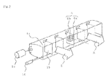
- Figure 1 is an appearance perspective view showing a dehumidifier of an embodiment
- Figure 2 is a schematic configuration view showing the inside of the dehumidifier of the embodiment
- Figure 3 is a schematic perspective view enlargedly showing wind direction changing means of Figure 1
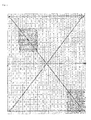
- Figure 4 is a schematic diagram showing the moving route of an infrared sensor used in detecting the dew condensation of a window pane, for example.
- the dehumidifier of this embodiment is made up of a dehumidifier cabinet 100, a air intake port 101 for taking the room air A into the dehumidifier cabinet 100, a water storage tank 102 which stores the moisture removed from the air taken into the air intake port 101, and an air outlet port 103 which discharges the moisture-removed dry air B from the dehumidifier cabinet 100 into a room.
- the air outlet port 103 is composed of wind direction changing means 1 which can change the wind direction of the dry air B.
- the wind direction changing means 1 is made up of a longitudinal louver 1a which changes the vertical wind direction and a lateral louver 1b which changes the horizontal wind direction.
- the water storage tank 102 is detachably mounted to the dehumidifier cabinet 100.
- the above-described dehumidifier is provided with an blowing fan 2 that generates an airflow that draws in the room air A through the air intake port 101 and discharges the dry air B through the air outlet port 103, a fan motor 2a which rotates the blowing fan 2, a temperature sensor 3 which detects the temperature of the room air A drawn in through the air intake port 101, a humidity sensor 4 which detects the humidity of the room air A, a dehumidifying means 5 which generates the dry air B by removing the moisture contained in the room air A, a longitudinal direction changing motor 1c which changes the longitudinal louver 1a in the vertical direction, a lateral direction changing motor 1d which changes the lateral louver 1b in the horizontal direction, an infrared ray sensor 6 that is a surface temperature detection means, and a control circuit 7 having a control means.
- an blowing fan 2 that generates an airflow that draws in the room air A through the air intake port 101 and discharges the dry air B through the air outlet port 103
- the dehumidification means 5 be capable of condensing the moisture in the air by removing the moisture, and for example, as the most common means, there are used the method which involves constituting a heat pump circuit and condensing the moisture in the air in a vaporizer and the desiccant method which involves condensing the moisture in the air removed by an adsorbent by use of a heat exchanger.
- the moisture removed from the room air A by the dehumidification means 5 is stored in the water storage tank 102 as the condensate water C.
- the longitudinal louver 1a has a rectangular opening extending in the width direction of the dehumidifier cabinet 100 and is constructed so that the direction thereof can be changed vertically with the rotating shaft of the above-described longitudinal direction changing motor 1c substantially as an axis.
- the lateral louvers 1b are arranged at equal intervals in the longitudinal louver 1a, are pivotally supported by the inner portions on the side opposite to the opening of the longitudinal louver 1a so that the directions thereof can be changed in the horizontal direction, and are configured so as to be moved in association with the drive of the above-described lateral direction changing motor 1d.
- the infrared sensor 6 is attached to one surface of a lateral louver 1b arranged within the longitudinal louver 1a substantially at the middle. As a result of this, the infrared sensor 6 detects the surface temperature of an object, for example, window panes and walls present in the blowing direction of the wind direction changing means 1.
- the detection range of the infrared sensor 6 is on the inner side of a blowing range obtained by changing the blowing direction of the wind direction changing means 1 vertically and laterally.
- the infrared sensor 6 is, for example, one which uses the thermoelectromotive effect is used, and is composed of an infrared ray absorbing film 6a which receives the heat radiations (infrared rays) generated from a surface in the detection range, and a thermistor 6b which detects the temperature of the infrared ray absorbing film 6a (see Figures 2 and 3 ).
- This infrared sensor 6 converts a difference between the temperature of a thermosensitive portion of the infrared ray absorbing film 6a (hot junction) whose temperature rises by absorbing heat radiations and the temperature of the infrared ray absorbing film 6a which is detected by the thermistor 6b (cold junction) to an electrical signal such as voltage, and inputs the electrical signal to the control circuit 7, which will be described later.
- a surface temperature in the detection range can be discriminated from the size of this electrical signal.
- the detection range of the infrared sensor 6 is divided laterally into 21 blocks and longitudinally into 21 blocks, a total of 441 blocks, coordinates are set for the arrangement position of each block, and the detection range is set in the control circuit 7 using the coordinates as data.
- the reason for this is that the surface temperature of each block detected by the infrared sensor 6 is recorded when the infrared sensor 6 is moved on the predetermined route shown in Figure 4 (thick lines).
- the louvers 1a, 1b are varied so that the infrared sensor 6 faces the block of coordinates (1, 1), which is the initial position of the detection range, and subsequently the louvers 1a, 1b are varied so that the infrared sensor 6 moves on the diagonal lines connecting the blocks of coordinates (1, 1) and coordinates (21,21).
- the infrared sensor 6 can be moved on the diagonal lines by making the variable speed of the lateral louver 1b faster than that of the longitudinal louver 1a.
- only the longitudinal louver 1a is varied so that the infrared sensor 6 moves on the vertical lines from the block of coordinates (21, 21) to the block of coordinates (21, 1).
- louvers 1a, 1b are varied so that the infrared sensor 6 moves on the diagonal lines connecting the blocks of coordinates (21, 1) and coordinates (1, 21). In the same manner as described above, also in this case, this is made possible by making the variable speed of the lateral louver 1b faster than that of the longitudinal louver 1a.
- the longitudinal louver 1a is varied so that the infrared sensor 6 moves on the vertical line from the block of coordinates (1, 21) to the block of coordinates (1, 1).
- the lateral louver 1b is varied so that the infrared sensor 6 moves to the block of coordinates (11, 1) at the middle of the lateral direction of the detection range.
- the lateral louver 1b turned forward and the longitudinal louver 1a is varied downward.
- variable speed of the longitudinal louver 1a and the variable speed of the lateral louver 1b are made almost the same, the infrared sensor 6 is moved to the block of coordinates (1, 1), which is the initial position, and the above-described actions are repeated.
- the control of the variable speed of the longitudinal louver 1a and the lateral louver 1b are performed through the control of the rotation speed of the longitudinal direction changing motor 1c and the lateral direction changing motor 1d by the control circuit 7.
- the above-described control circuit 7 permits blowing from the air outlet port 103 by driving the longitudinal direction changing motor 1c and lateral direction changing motor 1d of the wind direction changing means 1, rotates the blowing fan 2 by driving the fan motor 2a, and drives the humidification means 5.
- the control circuit 7 changes the direction of the louvers 1a, 1b by controlling the longitudinal direction changing motor 1c and lateral direction changing motor 1d of the wind direction changing means 1 so that the dry air B is blown in the direction of a desired region in the room.
- the room air A is taken from the air intake port 101 into the dehumidifier cabinet 100 and the temperature and humidity of the room are detected by the temperature sensor 3 and the humidity sensor 4, after which the room air A is dehumidified by the dehumidification means 5 and becomes the dry air B, which is blown out into the room from the air outlet port 103.
- the control circuit 7 controls the blowing direction of the wind direction changing means 1 to ensure that the infrared sensor 6 faces the initial position, which will be described in detail in the description of actions. Subsequently, the control circuit 7 controls the blowing direction of the wind direction changing means 1 so that the infrared sensor 6 moves on a predetermined route, and at the same time reads the surface temperature of each block on the predetermined route detected by the infrared sensor 6 (thick lines of Figure 4 ). After that, the control circuit 7 selects the lowest surface temperature from the read surface temperatures and makes a judgment as to whether the surface temperature is lower than a predetermined value.
- control circuit 7 judges that dew condensation has occurred, and controls the blowing direction of the wind direction changing means 1 so that the dry air is blown to the block of the surface temperature and the blocks in a predetermined range enclosing this block.
- the above-described predetermined value is a value obtained, for example, by subtracting predetermined ⁇ T from a room temperature detected by the temperature sensor 3.
- the room temperature is 20°C
- a predetermined value is not sought, and 20°C is used as the predetermined value, which is compared with the lowest surface temperature.
- FIG. 5 is a flowchart showing the actions of a dew condensation removal operation in the dehumidifier of the embodiment.
- the control circuit 7 of the dehumidifier Upon detection of the start of a dew condensation removal operation, the control circuit 7 of the dehumidifier permits blowing from the air outlet port 103 by driving the longitudinal direction changing motor 1c and lateral direction changing motor 1d of the wind direction changing means 1, rotates the blowing fan 2 by driving the fan motor 2a, and drives the humidification means 5.
- the control circuit 7 controls the longitudinal direction changing motor 1c and the lateral direction changing motor 1d so that the infrared sensor 6 faces the block of coordinates (1, 1) which is the initial position of the detection range of the infrared sensor 6 (S1). Subsequently, the control circuit 7 controls the longitudinal direction changing motor 1c and the lateral direction changing motor 1d so that the infrared sensor 6 moves in order on the routes of thick lines shown in Figure 4 , and at the same time reads the surface temperature (hereinafter referred to merely as "temperature") of each block on the predetermined route (thick lines of Figure 4 ) which are detected by the infrared sensor 6 (S2).
- temperature surface temperature
- control circuit 7 selects the lowest temperature from the read temperatures of the blocks (S3), and makes a judgment as to whether the lowest temperature is lower than a predetermined value (room temperature - ⁇ T) (S4).
- a predetermined value room temperature - ⁇ T
- the control circuit 7 moves the infrared sensor 6 present in the block of coordinates (11, 21) to the block of coordinates (1, 1), which is the initial position (S1), and repeats the above-described actions.
- the control circuit 7 sets the block of the lowest temperature and a predetermined range enclosing the block. For example, in the case where the coordinates of the block of the lowest temperature lower than a predetermined value are (16, 4) as shown in Figure 4 , the control circuit 7 sets X-coordinate - 2 at the left end and X-coordinate + 2 at the right end, the coordinates serving as the center. Furthermore, the control circuit sets, as a spot area, the area of the block in a range where Y-coordinate - 2 is at the top end and Y-coordinate + 2 is at the bottom end, coordinates (16, 4) serving as the center, i.e., the area of 5 x 5 blocks (S5).
- control circuit 7 causes the dry air B to strike the block of the initial coordinates (14, 4) of the spot area by turning the louvers 1a, 1b toward this block, varies only the longitudinal louver 1a downward from the position, and moves only the lateral louver 1b rightward by one block when the blowing direction of dry air B reaches coordinates (14, 8). Subsequently, the control circuit 7 varies only the longitudinal louver 1a upward from the position, and moves only the lateral louver 1b rightward by one block when the blowing direction of dry air B reaches coordinates (15, 4).
- the control circuit 7 repeats the action, and when the blowing direction of dry air B reaches coordinates (18, 8), makes a judgment as to whether, for example, 10 minutes set beforehand have elapsed (S7). When 10 minutes have not elapsed, the control circuit 7 turns the louvers 1a, 1b so that the dry air B strikes the block of the initial coordinates again, and repeats the above-described actions (S6).
- the control circuit 7 makes a judgment as to whether there exit other lowest temperatures lower than the predetermined value on the predetermined route (S8). For example, in the case where as shown in Figure 4 the coordinates of a block having the lowest temperature lower than the predetermined value are (1, 20), the control circuit 7 sets, as a new spot area, the area of 5 x 5 blocks where X-coordinates + 5 is at the right end, the coordinates serving as the center, and Y-coordinate - 3 is at the top end and Y-coordinate + 1 is at the bottom end, the coordinates serving as the center (S9).
- control circuit 7 causes the dry air B to strike the new spot area by varying the louvers 1a, 1b.
- the processing returns to S1, and the control circuit 7 repeats the above-described series of actions.
- the control circuit 7 sets, as a spot area, the area of 5 x 5 blocks where X-coordinates + 5 is at the right end, the coordinates serving as the center, and Y-coordinate - 3 is at the top end and Y-coordinate + 1 is at the bottom end, the coordinates serving as the center.
- Y-coordinate + 1 is adopted in this spot area is that an overlapping relation to the prior new spot area is avoided thereby.
- the blowing direction of the wind direction changing means 1 is controlled so that the infrared sensor 6 moves on a predetermined route in the detection range of the infrared sensor 6, and the temperatures (surface temperatures) of each block on the predetermined route detected by the infrared sensor 6 are read. And the lowest temperature is selected from the read temperatures and when the selected lowest temperature is lower than a predetermined value, the blowing direction of the wind direction changing means 1 is controlled so that the dry air B is blown to the block of the lowest temperature and to a spot area in a predetermined range (5 x 5 blocks) enclosing the block.
- a predetermined range 5 x 5 blocks
- the size of the spot area to which the dry air B is blown is 5 x 5 blocks.
- the size is not limited to this, and the spot area may be 7 x 7 blocks or 9 x 9 blocks, for example.
- the present invention can be applied to a dehumidifier which dries dew condensation occurring, for example, on wind panes and walls.
- 1 wind direction changing means 1a longitudinal louver, 1b lateral louvers, 1c longitudinal direction changing motor, 1d lateral direction changing motor, 2 blowing fan, 2a fan motor, 3 temperature sensor, 4 humidity sensor, 5 dehumidifying means, 6 infrared ray sensor, 6a infrared ray absorbing film, 6b thermistor, 7 control circuit, 100 dehumidifier cabinet, 101 air intake port, 102 water storage tank, 103 air outlet port, A room air, B dry air
Landscapes
- Engineering & Computer Science (AREA)
- Chemical & Material Sciences (AREA)
- Combustion & Propulsion (AREA)
- Mechanical Engineering (AREA)
- General Engineering & Computer Science (AREA)
- Analytical Chemistry (AREA)
- General Chemical & Material Sciences (AREA)
- Oil, Petroleum & Natural Gas (AREA)
- Chemical Kinetics & Catalysis (AREA)
- Air Conditioning Control Device (AREA)
- Drying Of Gases (AREA)
Abstract
Description
- The present invention relates to a dehumidifier which dries the dew condensation occurring on window panes and walls, for example.
- In conventional dehumidifiers, control means compares the result of temperature detection by infrared detection means with the result of temperature detection of the indoor atmosphere by temperature detection means, whereby a judgment is made on a sensible heat decrease due to the evaporation of the moisture absorbed by an object to be dried, and the location of the distribution of temperatures lower than the room temperature due to a sensible heat decrease of the object to be dried is judged to be in the range of arrangement of the object to be dried (refer to
Patent Literature 1, for example). - Patent literature 1: Japanese Patent Laid-Open No.
2007-240100 Figures 3 to 5 ) - However, although in the above-described conventional dehumidifiers, the location of a temperature distribution lower than the room temperature is in the arrangement range of an object to be dried, a low-temperature area exists in some parts of the room and this area may be judged to be in the arrangement range of an object to be dried and hence there is a possibility that it is impossible to cause the dry air to strike with good efficiency.
- The present invention was made in order to solve the problem described above, and it is an object of the invention to provide a dehumidifier which detects a place having the lowest temperature in the room without error and causes the dry air to strike the place in a concentrated manner.
- A dehumidifier according to the present invention, which comprises dehumidifying means which removes moisture contained in the air; and air blowing means which draws in room air and blows out dry air, which is obtained by causing the room air to pass through the dehumidifying means, into a room, comprises: wind direction changing means which changes a blowing direction of the dry air vertically and laterally; surface temperature detection means which is attached to the wind direction changing means and detects surface temperatures of an object present in the blowing direction of the wind direction changing means in a non-contact state; and control means which, upon detection of the start of a removal operation of dew condensation in the room, controls the blowing direction of the wind direction changing means so that the surface temperature detection means moves on a predetermined route in a surface temperature detection range obtained by changing the blowing direction of the wind direction changing means vertically and laterally, and also reads the surface temperatures on the predetermined route detected by the surface temperature detection means, and selects the lowest surface temperature from the read surface temperatures and controls the wind direction changing means so that the dry air is blown in the direction of the lowest surface temperature.
- In the present invention, upon detection of the start of a removal operation of dew condensation in the room, the blowing direction of the wind direction changing means is controlled so that the surface temperature detection means moves on a predetermined route in a surface temperature detection range obtained by changing the blowing direction of the wind direction changing means vertically and laterally, and the surface temperatures on the predetermined route detected by the surface temperature detection means are read. And the lowest surface temperature is selected from the read surface temperatures and the wind direction changing means is controlled so that the dry air is blown in the direction of the lowest surface temperature. As a result of this, it is possible to swiftly detect a place of the lowest temperature in the room and to perform drying with good efficiency.
-
-
Figure 1 is an appearance perspective view showing a dehumidifier of an embodiment. -
Figure 2 is a schematic configuration view showing the inside of the dehumidifier of the embodiment. -
Figure 3 is a schematic perspective view enlargedly showing wind direction changing means shown inFigure 1 . -
Figure 4 is a schematic diagram showing the moving route of an infrared sensor used in detecting the dew condensation of a window pane, for example. -
Figure 5 is a flowchart showing the actions of a dew condensation removal operation in the dehumidifier of the embodiment. -
Figure 1 is an appearance perspective view showing a dehumidifier of an embodiment,Figure 2 is a schematic configuration view showing the inside of the dehumidifier of the embodiment,Figure 3 is a schematic perspective view enlargedly showing wind direction changing means ofFigure 1 , andFigure 4 is a schematic diagram showing the moving route of an infrared sensor used in detecting the dew condensation of a window pane, for example. - As shown in
Figure 1 , the dehumidifier of this embodiment is made up of adehumidifier cabinet 100, aair intake port 101 for taking the room air A into thedehumidifier cabinet 100, awater storage tank 102 which stores the moisture removed from the air taken into theair intake port 101, and anair outlet port 103 which discharges the moisture-removed dry air B from thedehumidifier cabinet 100 into a room. Theair outlet port 103 is composed of winddirection changing means 1 which can change the wind direction of the dry air B. The winddirection changing means 1 is made up of a longitudinal louver 1a which changes the vertical wind direction and alateral louver 1b which changes the horizontal wind direction. Thewater storage tank 102 is detachably mounted to thedehumidifier cabinet 100. - As shown in
Figure 2 , the above-described dehumidifier is provided with an blowingfan 2 that generates an airflow that draws in the room air A through theair intake port 101 and discharges the dry air B through theair outlet port 103, afan motor 2a which rotates the blowingfan 2, atemperature sensor 3 which detects the temperature of the room air A drawn in through theair intake port 101, ahumidity sensor 4 which detects the humidity of the room air A, a dehumidifyingmeans 5 which generates the dry air B by removing the moisture contained in the room air A, a longitudinal direction changing motor 1c which changes the longitudinal louver 1a in the vertical direction, a lateraldirection changing motor 1d which changes thelateral louver 1b in the horizontal direction, aninfrared ray sensor 6 that is a surface temperature detection means, and acontrol circuit 7 having a control means. - It is necessary only that the dehumidification means 5 be capable of condensing the moisture in the air by removing the moisture, and for example, as the most common means, there are used the method which involves constituting a heat pump circuit and condensing the moisture in the air in a vaporizer and the desiccant method which involves condensing the moisture in the air removed by an adsorbent by use of a heat exchanger. The moisture removed from the room air A by the dehumidification means 5 is stored in the
water storage tank 102 as the condensate water C. - As shown in
Figure 3 , the longitudinal louver 1a has a rectangular opening extending in the width direction of thedehumidifier cabinet 100 and is constructed so that the direction thereof can be changed vertically with the rotating shaft of the above-described longitudinal direction changing motor 1c substantially as an axis. Thelateral louvers 1b are arranged at equal intervals in the longitudinal louver 1a, are pivotally supported by the inner portions on the side opposite to the opening of the longitudinal louver 1a so that the directions thereof can be changed in the horizontal direction, and are configured so as to be moved in association with the drive of the above-described lateraldirection changing motor 1d. - The
infrared sensor 6 is attached to one surface of alateral louver 1b arranged within the longitudinal louver 1a substantially at the middle. As a result of this, theinfrared sensor 6 detects the surface temperature of an object, for example, window panes and walls present in the blowing direction of the winddirection changing means 1. The detection range of theinfrared sensor 6 is on the inner side of a blowing range obtained by changing the blowing direction of the winddirection changing means 1 vertically and laterally. Theinfrared sensor 6 is, for example, one which uses the thermoelectromotive effect is used, and is composed of an infrared ray absorbing film 6a which receives the heat radiations (infrared rays) generated from a surface in the detection range, and athermistor 6b which detects the temperature of the infrared ray absorbing film 6a (seeFigures 2 and3 ). Thisinfrared sensor 6 converts a difference between the temperature of a thermosensitive portion of the infrared ray absorbing film 6a (hot junction) whose temperature rises by absorbing heat radiations and the temperature of the infrared ray absorbing film 6a which is detected by thethermistor 6b (cold junction) to an electrical signal such as voltage, and inputs the electrical signal to thecontrol circuit 7, which will be described later. A surface temperature in the detection range can be discriminated from the size of this electrical signal. - In this embodiment, for example as shown in
Figure 4 , the detection range of theinfrared sensor 6 is divided laterally into 21 blocks and longitudinally into 21 blocks, a total of 441 blocks, coordinates are set for the arrangement position of each block, and the detection range is set in thecontrol circuit 7 using the coordinates as data. The reason for this is that the surface temperature of each block detected by theinfrared sensor 6 is recorded when theinfrared sensor 6 is moved on the predetermined route shown inFigure 4 (thick lines). - When dew condensation is detected, first, the
louvers 1a, 1b are varied so that theinfrared sensor 6 faces the block of coordinates (1, 1), which is the initial position of the detection range, and subsequently thelouvers 1a, 1b are varied so that theinfrared sensor 6 moves on the diagonal lines connecting the blocks of coordinates (1, 1) and coordinates (21,21). In this case, theinfrared sensor 6 can be moved on the diagonal lines by making the variable speed of thelateral louver 1b faster than that of the longitudinal louver 1a. Next, only the longitudinal louver 1a is varied so that theinfrared sensor 6 moves on the vertical lines from the block of coordinates (21, 21) to the block of coordinates (21, 1). After that, thelouvers 1a, 1b are varied so that theinfrared sensor 6 moves on the diagonal lines connecting the blocks of coordinates (21, 1) and coordinates (1, 21). In the same manner as described above, also in this case, this is made possible by making the variable speed of thelateral louver 1b faster than that of the longitudinal louver 1a. - Furthermore, only the longitudinal louver 1a is varied so that the
infrared sensor 6 moves on the vertical line from the block of coordinates (1, 21) to the block of coordinates (1, 1). After that, only thelateral louver 1b is varied so that theinfrared sensor 6 moves to the block of coordinates (11, 1) at the middle of the lateral direction of the detection range. Subsequently, in order to ensure that theinfrared sensor 6 moves on the vertical line from the block of coordinates (11, 1) to the block of coordinates (11, 21), thelateral louver 1b turned forward and the longitudinal louver 1a is varied downward. When the orientation of theinfrared sensor 6 has reached the block of coordinates (11, 21), the variable speed of the longitudinal louver 1a and the variable speed of thelateral louver 1b are made almost the same, theinfrared sensor 6 is moved to the block of coordinates (1, 1), which is the initial position, and the above-described actions are repeated. The control of the variable speed of the longitudinal louver 1a and thelateral louver 1b are performed through the control of the rotation speed of the longitudinal direction changing motor 1c and the lateraldirection changing motor 1d by thecontrol circuit 7. - When the selection of an ordinary dehumidification mode from an operating switch of an operation section, which is not shown, has been detected, the above-described
control circuit 7 permits blowing from theair outlet port 103 by driving the longitudinal direction changing motor 1c and lateraldirection changing motor 1d of the winddirection changing means 1, rotates the blowingfan 2 by driving thefan motor 2a, and drives the humidification means 5. After that, thecontrol circuit 7 changes the direction of thelouvers 1a, 1b by controlling the longitudinal direction changing motor 1c and lateraldirection changing motor 1d of the winddirection changing means 1 so that the dry air B is blown in the direction of a desired region in the room. As a result of this, the room air A is taken from theair intake port 101 into thedehumidifier cabinet 100 and the temperature and humidity of the room are detected by thetemperature sensor 3 and thehumidity sensor 4, after which the room air A is dehumidified by the dehumidification means 5 and becomes the dry air B, which is blown out into the room from theair outlet port 103. - Furthermore, upon detection of the start of a dew condensation removal operation, the
control circuit 7 controls the blowing direction of the winddirection changing means 1 to ensure that theinfrared sensor 6 faces the initial position, which will be described in detail in the description of actions. Subsequently, thecontrol circuit 7 controls the blowing direction of the wind direction changing means 1 so that theinfrared sensor 6 moves on a predetermined route, and at the same time reads the surface temperature of each block on the predetermined route detected by the infrared sensor 6 (thick lines ofFigure 4 ). After that, thecontrol circuit 7 selects the lowest surface temperature from the read surface temperatures and makes a judgment as to whether the surface temperature is lower than a predetermined value. When the lowest surface temperature is lower than the predetermined value, thecontrol circuit 7 judges that dew condensation has occurred, and controls the blowing direction of the winddirection changing means 1 so that the dry air is blown to the block of the surface temperature and the blocks in a predetermined range enclosing this block. - The above-described predetermined value is a value obtained, for example, by subtracting predetermined ΔT from a room temperature detected by the
temperature sensor 3. Incidentally, when the room temperature is 20°C, for example, a predetermined value is not sought, and 20°C is used as the predetermined value, which is compared with the lowest surface temperature. - Next, with reference to
Figure 5 , a description will be given of actions taken when a dew condensation removal operation is selected.
Figure 5 is a flowchart showing the actions of a dew condensation removal operation in the dehumidifier of the embodiment.
Upon detection of the start of a dew condensation removal operation, thecontrol circuit 7 of the dehumidifier permits blowing from theair outlet port 103 by driving the longitudinal direction changing motor 1c and lateraldirection changing motor 1d of the winddirection changing means 1, rotates the blowingfan 2 by driving thefan motor 2a, and drives the humidification means 5. After that, thecontrol circuit 7 controls the longitudinal direction changing motor 1c and the lateraldirection changing motor 1d so that theinfrared sensor 6 faces the block of coordinates (1, 1) which is the initial position of the detection range of the infrared sensor 6 (S1). Subsequently, thecontrol circuit 7 controls the longitudinal direction changing motor 1c and the lateraldirection changing motor 1d so that theinfrared sensor 6 moves in order on the routes of thick lines shown inFigure 4 , and at the same time reads the surface temperature (hereinafter referred to merely as "temperature") of each block on the predetermined route (thick lines ofFigure 4 ) which are detected by the infrared sensor 6 (S2). - And the
control circuit 7 selects the lowest temperature from the read temperatures of the blocks (S3), and makes a judgment as to whether the lowest temperature is lower than a predetermined value (room temperature - ΔT) (S4). When the lowest temperature is higher than the predetermined value, thecontrol circuit 7 moves theinfrared sensor 6 present in the block of coordinates (11, 21) to the block of coordinates (1, 1), which is the initial position (S1), and repeats the above-described actions. - When the selected lowest temperature is lower than the predetermined value, the
control circuit 7 sets the block of the lowest temperature and a predetermined range enclosing the block. For example, in the case where the coordinates of the block of the lowest temperature lower than a predetermined value are (16, 4) as shown inFigure 4 , thecontrol circuit 7 sets X-coordinate - 2 at the left end and X-coordinate + 2 at the right end, the coordinates serving as the center. Furthermore, the control circuit sets, as a spot area, the area of the block in a range where Y-coordinate - 2 is at the top end and Y-coordinate + 2 is at the bottom end, coordinates (16, 4) serving as the center, i.e., the area of 5 x 5 blocks (S5). - And the
control circuit 7 causes the dry air B to strike the block of the initial coordinates (14, 4) of the spot area by turning thelouvers 1a, 1b toward this block, varies only the longitudinal louver 1a downward from the position, and moves only thelateral louver 1b rightward by one block when the blowing direction of dry air B reaches coordinates (14, 8). Subsequently, thecontrol circuit 7 varies only the longitudinal louver 1a upward from the position, and moves only thelateral louver 1b rightward by one block when the blowing direction of dry air B reaches coordinates (15, 4). Thecontrol circuit 7 repeats the action, and when the blowing direction of dry air B reaches coordinates (18, 8), makes a judgment as to whether, for example, 10 minutes set beforehand have elapsed (S7). When 10 minutes have not elapsed, thecontrol circuit 7 turns thelouvers 1a, 1b so that the dry air B strikes the block of the initial coordinates again, and repeats the above-described actions (S6). - When 10 minutes have elapsed during the repeated blowing of the dry air B to the set spot area, the
control circuit 7 makes a judgment as to whether there exit other lowest temperatures lower than the predetermined value on the predetermined route (S8). For example, in the case where as shown inFigure 4 the coordinates of a block having the lowest temperature lower than the predetermined value are (1, 20), thecontrol circuit 7 sets, as a new spot area, the area of 5 x 5 blocks where X-coordinates + 5 is at the right end, the coordinates serving as the center, and Y-coordinate - 3 is at the top end and Y-coordinate + 1 is at the bottom end, the coordinates serving as the center (S9). After that, for 10 minutes in the same manner as described above, thecontrol circuit 7 causes the dry air B to strike the new spot area by varying thelouvers 1a, 1b. When in S8 thecontrol circuit 7 judges that there is no other lowest temperature lower than the predetermined value on the predetermined route, the processing returns to S1, and thecontrol circuit 7 repeats the above-described series of actions. - Furthermore, after the finish of the blowing of the dry air B to the new spot area, in the case where, for example, the temperature of the block of coordinates (1, 15) is lower than the predetermined value, the
control circuit 7 sets, as a spot area, the area of 5 x 5 blocks where X-coordinates + 5 is at the right end, the coordinates serving as the center, and Y-coordinate - 3 is at the top end and Y-coordinate + 1 is at the bottom end, the coordinates serving as the center. The reason why Y-coordinate + 1 is adopted in this spot area is that an overlapping relation to the prior new spot area is avoided thereby. - As described above, according to this embodiment, during a dew condensation removal operation, the blowing direction of the wind
direction changing means 1 is controlled so that theinfrared sensor 6 moves on a predetermined route in the detection range of theinfrared sensor 6, and the temperatures (surface temperatures) of each block on the predetermined route detected by theinfrared sensor 6 are read. And the lowest temperature is selected from the read temperatures and when the selected lowest temperature is lower than a predetermined value, the blowing direction of the winddirection changing means 1 is controlled so that the dry air B is blown to the block of the lowest temperature and to a spot area in a predetermined range (5 x 5 blocks) enclosing the block. As a result of this, it is possible to swiftly detect dew condensation occurring on the window panes and walls without error and it is possible to perform drying with good efficiency. - Incidentally, in this embodiment, the size of the spot area to which the dry air B is blown is 5 x 5 blocks. However, the size is not limited to this, and the spot area may be 7 x 7 blocks or 9 x 9 blocks, for example.
- Furthermore, because the temperature distribution in the room becomes almost uniform in rainy seasons and the like, it is possible to add control permitting switching to wide blowing instead of spot blowing in order to circulate the air in the whole room.
- The present invention can be applied to a dehumidifier which dries dew condensation occurring, for example, on wind panes and walls.
- 1 wind direction changing means, 1a longitudinal louver, 1b lateral louvers, 1c longitudinal direction changing motor, 1d lateral direction changing motor, 2 blowing fan, 2a fan motor, 3 temperature sensor, 4 humidity sensor, 5 dehumidifying means, 6 infrared ray sensor, 6a infrared ray absorbing film, 6b thermistor, 7 control circuit, 100 dehumidifier cabinet, 101 air intake port, 102 water storage tank, 103 air outlet port, A room air, B dry air
Claims (4)
- A dehumidifier which comprises dehumidifying means which removes moisture contained in the air; and air blowing means which draws in room air and blows out dry air, which is obtained by causing the room air to pass through the dehumidifying means, into a room, comprising:wind direction changing means which changes a blowing direction of the dry air vertically and laterally;surface temperature detection means which is attached to the wind direction changing means and detects surface temperatures of an object present in the blowing direction of the wind direction changing means in a non-contact state; andcontrol means which, upon detection of the start of a removal operation of dew condensation in the room, controls the blowing direction of the wind direction changing means so that the surface temperature detection means moves on a predetermined route in a surface temperature detection range obtained by changing the blowing direction of the wind direction changing means vertically and laterally, and also reads the surface temperatures on the predetermined route detected by the surface temperature detection means, and selects the lowest surface temperature from the read surface temperatures and controls the wind direction changing means so that the dry air is blown in the direction of the lowest surface temperature.
- The dehumidifier according to claim 1, wherein upon selecting the lowest surface temperature from the read surface temperatures, the control means makes a judgment as to whether the surface temperature is lower than a predetermined value, and controls the wind direction changing means so that the dry air is blown in the direction of the surface temperature when the lowest surface temperature is lower than the predetermined value.
- The dehumidifier according to claim 1 or 2, wherein in blowing the dry air in the direction of the above-described surface temperature, the control means sets an area of a predetermined range on the basis of the blowing direction and controls the wind direction changing means so that the dry air is blown into the area.
- The dehumidifier according to claim 1 or 2, wherein the predetermined route includes two diagonal lines which pass through the center of the surface temperature detection range.
Applications Claiming Priority (2)
| Application Number | Priority Date | Filing Date | Title |
|---|---|---|---|
| JP2010050445 | 2010-03-08 | ||
| PCT/JP2011/053762 WO2011111514A1 (en) | 2010-03-08 | 2011-02-22 | Dehumidifier |
Publications (3)
| Publication Number | Publication Date |
|---|---|
| EP2545979A1 true EP2545979A1 (en) | 2013-01-16 |
| EP2545979A4 EP2545979A4 (en) | 2014-03-12 |
| EP2545979B1 EP2545979B1 (en) | 2019-03-27 |
Family
ID=44563330
Family Applications (1)
| Application Number | Title | Priority Date | Filing Date |
|---|---|---|---|
| EP11753176.4A Active EP2545979B1 (en) | 2010-03-08 | 2011-02-22 | Dehumidifier |
Country Status (6)
| Country | Link |
|---|---|
| EP (1) | EP2545979B1 (en) |
| JP (1) | JP5776683B2 (en) |
| CN (1) | CN102781552B (en) |
| NZ (1) | NZ601292A (en) |
| TW (1) | TWI427246B (en) |
| WO (1) | WO2011111514A1 (en) |
Cited By (1)
| Publication number | Priority date | Publication date | Assignee | Title |
|---|---|---|---|---|
| US20190276936A1 (en) * | 2018-03-09 | 2019-09-12 | Tokyo Electron Limited | Condensation suppressing method and processing system |
Families Citing this family (4)
| Publication number | Priority date | Publication date | Assignee | Title |
|---|---|---|---|---|
| JP6816737B2 (en) * | 2018-03-29 | 2021-01-20 | 三菱電機株式会社 | Dehumidifier |
| CN113584851B (en) * | 2020-04-30 | 2023-12-12 | 云米互联科技(广东)有限公司 | Fan operating method, fan and computer-readable storage medium |
| CN113883881B (en) * | 2021-10-15 | 2023-10-20 | 珠海格力电器股份有限公司 | Baffle structure, air duct, drying equipment, drying system and control method |
| CN114405269B (en) * | 2022-02-09 | 2023-06-30 | 威海海洋职业学院 | Boats and ships tail gas SOx/NOx control integrated processing device |
Family Cites Families (11)
| Publication number | Priority date | Publication date | Assignee | Title |
|---|---|---|---|---|
| JP2002333185A (en) * | 2001-05-11 | 2002-11-22 | Sanyo Electric Co Ltd | Air conditioner with dehumidifying operation function |
| JP2002340387A (en) * | 2001-05-16 | 2002-11-27 | Sanyo Electric Co Ltd | Air conditioner with dehumidifying operation function |
| JP2005315454A (en) * | 2004-04-27 | 2005-11-10 | Matsushita Electric Ind Co Ltd | Heating device and air conditioner using the same |
| JP4752489B2 (en) * | 2005-12-20 | 2011-08-17 | パナソニック株式会社 | Wind direction change device |
| JP4704937B2 (en) * | 2006-03-08 | 2011-06-22 | シャープ株式会社 | Wind direction change device |
| JP4915111B2 (en) * | 2006-03-10 | 2012-04-11 | パナソニック株式会社 | Dehumidifier |
| JP2008023486A (en) * | 2006-07-24 | 2008-02-07 | Toshiba Home Technology Corp | Dehumidifier |
| CN201043784Y (en) * | 2007-03-21 | 2008-04-02 | 富利佳电子(东莞)有限公司 | Improved structure of dehumidifier |
| JP2009092252A (en) * | 2007-10-04 | 2009-04-30 | Mitsubishi Electric Corp | Air conditioner |
| JP2009192165A (en) * | 2008-02-15 | 2009-08-27 | Mitsubishi Electric Corp | Dehumidifier |
| JP5211811B2 (en) * | 2008-04-07 | 2013-06-12 | パナソニック株式会社 | Bathroom heating dryer |
-
2011
- 2011-02-22 EP EP11753176.4A patent/EP2545979B1/en active Active
- 2011-02-22 WO PCT/JP2011/053762 patent/WO2011111514A1/en not_active Ceased
- 2011-02-22 CN CN201180011546.1A patent/CN102781552B/en not_active Expired - Fee Related
- 2011-02-22 NZ NZ601292A patent/NZ601292A/en not_active IP Right Cessation
- 2011-02-22 JP JP2012504392A patent/JP5776683B2/en not_active Expired - Fee Related
- 2011-03-01 TW TW100106613A patent/TWI427246B/en not_active IP Right Cessation
Cited By (2)
| Publication number | Priority date | Publication date | Assignee | Title |
|---|---|---|---|---|
| US20190276936A1 (en) * | 2018-03-09 | 2019-09-12 | Tokyo Electron Limited | Condensation suppressing method and processing system |
| US10961627B2 (en) * | 2018-03-09 | 2021-03-30 | Tokyo Electron Limited | Condensation suppressing method and processing system |
Also Published As
| Publication number | Publication date |
|---|---|
| WO2011111514A1 (en) | 2011-09-15 |
| TW201200815A (en) | 2012-01-01 |
| CN102781552A (en) | 2012-11-14 |
| HK1174001A1 (en) | 2013-05-31 |
| TWI427246B (en) | 2014-02-21 |
| JPWO2011111514A1 (en) | 2013-06-27 |
| JP5776683B2 (en) | 2015-09-09 |
| NZ601292A (en) | 2014-02-28 |
| CN102781552B (en) | 2016-04-27 |
| EP2545979B1 (en) | 2019-03-27 |
| EP2545979A4 (en) | 2014-03-12 |
Similar Documents
| Publication | Publication Date | Title |
|---|---|---|
| JP5984666B2 (en) | Dehumidifier | |
| EP2832919B1 (en) | Dehumidifier | |
| JP6104303B2 (en) | Air conditioner | |
| TWI608196B (en) | air conditioner | |
| EP2545979B1 (en) | Dehumidifier | |
| CN104246383B (en) | Air conditioner | |
| JP5610797B2 (en) | Dehumidifier | |
| EP2837734A1 (en) | Air conditioner | |
| HK1174001B (en) | Dehumidifier | |
| HK1174002B (en) | Dehumidifier | |
| HK1199913B (en) | Dehumidifier | |
| HK1187975B (en) | Air conditioner | |
| NZ613995B2 (en) | Air-conditioning apparatus | |
| HK1200509B (en) | Air conditioner |
Legal Events
| Date | Code | Title | Description |
|---|---|---|---|
| PUAI | Public reference made under article 153(3) epc to a published international application that has entered the european phase |
Free format text: ORIGINAL CODE: 0009012 |
|
| 17P | Request for examination filed |
Effective date: 20120905 |
|
| AK | Designated contracting states |
Kind code of ref document: A1 Designated state(s): AL AT BE BG CH CY CZ DE DK EE ES FI FR GB GR HR HU IE IS IT LI LT LU LV MC MK MT NL NO PL PT RO RS SE SI SK SM TR |
|
| DAX | Request for extension of the european patent (deleted) | ||
| A4 | Supplementary search report drawn up and despatched |
Effective date: 20140207 |
|
| RIC1 | Information provided on ipc code assigned before grant |
Ipc: F24F 1/02 20110101ALI20140203BHEP Ipc: F26B 21/00 20060101ALI20140203BHEP Ipc: D06F 58/28 20060101ALI20140203BHEP Ipc: F24F 11/00 20060101ALI20140203BHEP Ipc: F24F 11/02 20060101ALI20140203BHEP Ipc: B01D 53/26 20060101AFI20140203BHEP Ipc: F24F 3/14 20060101ALI20140203BHEP |
|
| REG | Reference to a national code |
Ref country code: DE Ref legal event code: R079 Ref document number: 602011057534 Country of ref document: DE Free format text: PREVIOUS MAIN CLASS: B01D0053260000 Ipc: F24F0110100000 |
|
| GRAP | Despatch of communication of intention to grant a patent |
Free format text: ORIGINAL CODE: EPIDOSNIGR1 |
|
| STAA | Information on the status of an ep patent application or granted ep patent |
Free format text: STATUS: GRANT OF PATENT IS INTENDED |
|
| RIC1 | Information provided on ipc code assigned before grant |
Ipc: F24F 11/79 20180101ALI20180910BHEP Ipc: F24F 3/14 20060101ALI20180910BHEP Ipc: F24F 13/22 20060101ALI20180910BHEP Ipc: B01D 53/26 20060101ALI20180910BHEP Ipc: F24F 110/10 20180101AFI20180910BHEP |
|
| INTG | Intention to grant announced |
Effective date: 20181008 |
|
| GRAS | Grant fee paid |
Free format text: ORIGINAL CODE: EPIDOSNIGR3 |
|
| GRAA | (expected) grant |
Free format text: ORIGINAL CODE: 0009210 |
|
| STAA | Information on the status of an ep patent application or granted ep patent |
Free format text: STATUS: THE PATENT HAS BEEN GRANTED |
|
| AK | Designated contracting states |
Kind code of ref document: B1 Designated state(s): AL AT BE BG CH CY CZ DE DK EE ES FI FR GB GR HR HU IE IS IT LI LT LU LV MC MK MT NL NO PL PT RO RS SE SI SK SM TR |
|
| REG | Reference to a national code |
Ref country code: GB Ref legal event code: FG4D |
|
| REG | Reference to a national code |
Ref country code: CH Ref legal event code: EP |
|
| REG | Reference to a national code |
Ref country code: AT Ref legal event code: REF Ref document number: 1113560 Country of ref document: AT Kind code of ref document: T Effective date: 20190415 |
|
| REG | Reference to a national code |
Ref country code: IE Ref legal event code: FG4D |
|
| REG | Reference to a national code |
Ref country code: DE Ref legal event code: R096 Ref document number: 602011057534 Country of ref document: DE |
|
| PG25 | Lapsed in a contracting state [announced via postgrant information from national office to epo] |
Ref country code: FI Free format text: LAPSE BECAUSE OF FAILURE TO SUBMIT A TRANSLATION OF THE DESCRIPTION OR TO PAY THE FEE WITHIN THE PRESCRIBED TIME-LIMIT Effective date: 20190327 Ref country code: NO Free format text: LAPSE BECAUSE OF FAILURE TO SUBMIT A TRANSLATION OF THE DESCRIPTION OR TO PAY THE FEE WITHIN THE PRESCRIBED TIME-LIMIT Effective date: 20190627 Ref country code: SE Free format text: LAPSE BECAUSE OF FAILURE TO SUBMIT A TRANSLATION OF THE DESCRIPTION OR TO PAY THE FEE WITHIN THE PRESCRIBED TIME-LIMIT Effective date: 20190327 Ref country code: LT Free format text: LAPSE BECAUSE OF FAILURE TO SUBMIT A TRANSLATION OF THE DESCRIPTION OR TO PAY THE FEE WITHIN THE PRESCRIBED TIME-LIMIT Effective date: 20190327 |
|
| REG | Reference to a national code |
Ref country code: NL Ref legal event code: MP Effective date: 20190327 |
|
| PG25 | Lapsed in a contracting state [announced via postgrant information from national office to epo] |
Ref country code: LV Free format text: LAPSE BECAUSE OF FAILURE TO SUBMIT A TRANSLATION OF THE DESCRIPTION OR TO PAY THE FEE WITHIN THE PRESCRIBED TIME-LIMIT Effective date: 20190327 Ref country code: HR Free format text: LAPSE BECAUSE OF FAILURE TO SUBMIT A TRANSLATION OF THE DESCRIPTION OR TO PAY THE FEE WITHIN THE PRESCRIBED TIME-LIMIT Effective date: 20190327 Ref country code: NL Free format text: LAPSE BECAUSE OF FAILURE TO SUBMIT A TRANSLATION OF THE DESCRIPTION OR TO PAY THE FEE WITHIN THE PRESCRIBED TIME-LIMIT Effective date: 20190327 Ref country code: BG Free format text: LAPSE BECAUSE OF FAILURE TO SUBMIT A TRANSLATION OF THE DESCRIPTION OR TO PAY THE FEE WITHIN THE PRESCRIBED TIME-LIMIT Effective date: 20190627 Ref country code: GR Free format text: LAPSE BECAUSE OF FAILURE TO SUBMIT A TRANSLATION OF THE DESCRIPTION OR TO PAY THE FEE WITHIN THE PRESCRIBED TIME-LIMIT Effective date: 20190628 Ref country code: RS Free format text: LAPSE BECAUSE OF FAILURE TO SUBMIT A TRANSLATION OF THE DESCRIPTION OR TO PAY THE FEE WITHIN THE PRESCRIBED TIME-LIMIT Effective date: 20190327 |
|
| REG | Reference to a national code |
Ref country code: AT Ref legal event code: MK05 Ref document number: 1113560 Country of ref document: AT Kind code of ref document: T Effective date: 20190327 |
|
| PG25 | Lapsed in a contracting state [announced via postgrant information from national office to epo] |
Ref country code: EE Free format text: LAPSE BECAUSE OF FAILURE TO SUBMIT A TRANSLATION OF THE DESCRIPTION OR TO PAY THE FEE WITHIN THE PRESCRIBED TIME-LIMIT Effective date: 20190327 Ref country code: SK Free format text: LAPSE BECAUSE OF FAILURE TO SUBMIT A TRANSLATION OF THE DESCRIPTION OR TO PAY THE FEE WITHIN THE PRESCRIBED TIME-LIMIT Effective date: 20190327 Ref country code: RO Free format text: LAPSE BECAUSE OF FAILURE TO SUBMIT A TRANSLATION OF THE DESCRIPTION OR TO PAY THE FEE WITHIN THE PRESCRIBED TIME-LIMIT Effective date: 20190327 Ref country code: CZ Free format text: LAPSE BECAUSE OF FAILURE TO SUBMIT A TRANSLATION OF THE DESCRIPTION OR TO PAY THE FEE WITHIN THE PRESCRIBED TIME-LIMIT Effective date: 20190327 Ref country code: AL Free format text: LAPSE BECAUSE OF FAILURE TO SUBMIT A TRANSLATION OF THE DESCRIPTION OR TO PAY THE FEE WITHIN THE PRESCRIBED TIME-LIMIT Effective date: 20190327 Ref country code: PT Free format text: LAPSE BECAUSE OF FAILURE TO SUBMIT A TRANSLATION OF THE DESCRIPTION OR TO PAY THE FEE WITHIN THE PRESCRIBED TIME-LIMIT Effective date: 20190727 Ref country code: ES Free format text: LAPSE BECAUSE OF FAILURE TO SUBMIT A TRANSLATION OF THE DESCRIPTION OR TO PAY THE FEE WITHIN THE PRESCRIBED TIME-LIMIT Effective date: 20190327 |
|
| PG25 | Lapsed in a contracting state [announced via postgrant information from national office to epo] |
Ref country code: PL Free format text: LAPSE BECAUSE OF FAILURE TO SUBMIT A TRANSLATION OF THE DESCRIPTION OR TO PAY THE FEE WITHIN THE PRESCRIBED TIME-LIMIT Effective date: 20190327 Ref country code: SM Free format text: LAPSE BECAUSE OF FAILURE TO SUBMIT A TRANSLATION OF THE DESCRIPTION OR TO PAY THE FEE WITHIN THE PRESCRIBED TIME-LIMIT Effective date: 20190327 |
|
| PG25 | Lapsed in a contracting state [announced via postgrant information from national office to epo] |
Ref country code: AT Free format text: LAPSE BECAUSE OF FAILURE TO SUBMIT A TRANSLATION OF THE DESCRIPTION OR TO PAY THE FEE WITHIN THE PRESCRIBED TIME-LIMIT Effective date: 20190327 Ref country code: IS Free format text: LAPSE BECAUSE OF FAILURE TO SUBMIT A TRANSLATION OF THE DESCRIPTION OR TO PAY THE FEE WITHIN THE PRESCRIBED TIME-LIMIT Effective date: 20190727 |
|
| REG | Reference to a national code |
Ref country code: DE Ref legal event code: R097 Ref document number: 602011057534 Country of ref document: DE |
|
| PG25 | Lapsed in a contracting state [announced via postgrant information from national office to epo] |
Ref country code: DK Free format text: LAPSE BECAUSE OF FAILURE TO SUBMIT A TRANSLATION OF THE DESCRIPTION OR TO PAY THE FEE WITHIN THE PRESCRIBED TIME-LIMIT Effective date: 20190327 |
|
| PLBE | No opposition filed within time limit |
Free format text: ORIGINAL CODE: 0009261 |
|
| STAA | Information on the status of an ep patent application or granted ep patent |
Free format text: STATUS: NO OPPOSITION FILED WITHIN TIME LIMIT |
|
| PG25 | Lapsed in a contracting state [announced via postgrant information from national office to epo] |
Ref country code: SI Free format text: LAPSE BECAUSE OF FAILURE TO SUBMIT A TRANSLATION OF THE DESCRIPTION OR TO PAY THE FEE WITHIN THE PRESCRIBED TIME-LIMIT Effective date: 20190327 |
|
| 26N | No opposition filed |
Effective date: 20200103 |
|
| PG25 | Lapsed in a contracting state [announced via postgrant information from national office to epo] |
Ref country code: TR Free format text: LAPSE BECAUSE OF FAILURE TO SUBMIT A TRANSLATION OF THE DESCRIPTION OR TO PAY THE FEE WITHIN THE PRESCRIBED TIME-LIMIT Effective date: 20190327 |
|
| REG | Reference to a national code |
Ref country code: DE Ref legal event code: R119 Ref document number: 602011057534 Country of ref document: DE |
|
| REG | Reference to a national code |
Ref country code: CH Ref legal event code: PL |
|
| GBPC | Gb: european patent ceased through non-payment of renewal fee |
Effective date: 20200222 |
|
| REG | Reference to a national code |
Ref country code: BE Ref legal event code: MM Effective date: 20200229 |
|
| PG25 | Lapsed in a contracting state [announced via postgrant information from national office to epo] |
Ref country code: MC Free format text: LAPSE BECAUSE OF FAILURE TO SUBMIT A TRANSLATION OF THE DESCRIPTION OR TO PAY THE FEE WITHIN THE PRESCRIBED TIME-LIMIT Effective date: 20190327 Ref country code: LU Free format text: LAPSE BECAUSE OF NON-PAYMENT OF DUE FEES Effective date: 20200222 |
|
| PG25 | Lapsed in a contracting state [announced via postgrant information from national office to epo] |
Ref country code: CH Free format text: LAPSE BECAUSE OF NON-PAYMENT OF DUE FEES Effective date: 20200229 Ref country code: LI Free format text: LAPSE BECAUSE OF NON-PAYMENT OF DUE FEES Effective date: 20200229 |
|
| PG25 | Lapsed in a contracting state [announced via postgrant information from national office to epo] |
Ref country code: GB Free format text: LAPSE BECAUSE OF NON-PAYMENT OF DUE FEES Effective date: 20200222 Ref country code: DE Free format text: LAPSE BECAUSE OF NON-PAYMENT OF DUE FEES Effective date: 20200901 Ref country code: IE Free format text: LAPSE BECAUSE OF NON-PAYMENT OF DUE FEES Effective date: 20200222 Ref country code: FR Free format text: LAPSE BECAUSE OF NON-PAYMENT OF DUE FEES Effective date: 20200229 |
|
| PG25 | Lapsed in a contracting state [announced via postgrant information from national office to epo] |
Ref country code: BE Free format text: LAPSE BECAUSE OF NON-PAYMENT OF DUE FEES Effective date: 20200229 |
|
| PG25 | Lapsed in a contracting state [announced via postgrant information from national office to epo] |
Ref country code: IT Free format text: LAPSE BECAUSE OF NON-PAYMENT OF DUE FEES Effective date: 20200222 |
|
| PG25 | Lapsed in a contracting state [announced via postgrant information from national office to epo] |
Ref country code: MT Free format text: LAPSE BECAUSE OF FAILURE TO SUBMIT A TRANSLATION OF THE DESCRIPTION OR TO PAY THE FEE WITHIN THE PRESCRIBED TIME-LIMIT Effective date: 20190327 Ref country code: CY Free format text: LAPSE BECAUSE OF FAILURE TO SUBMIT A TRANSLATION OF THE DESCRIPTION OR TO PAY THE FEE WITHIN THE PRESCRIBED TIME-LIMIT Effective date: 20190327 |
|
| PG25 | Lapsed in a contracting state [announced via postgrant information from national office to epo] |
Ref country code: MK Free format text: LAPSE BECAUSE OF FAILURE TO SUBMIT A TRANSLATION OF THE DESCRIPTION OR TO PAY THE FEE WITHIN THE PRESCRIBED TIME-LIMIT Effective date: 20190327 |
|
| P01 | Opt-out of the competence of the unified patent court (upc) registered |
Effective date: 20230512 |