EP2545853A1 - Electrochemical sensor - Google Patents
Electrochemical sensor Download PDFInfo
- Publication number
- EP2545853A1 EP2545853A1 EP11753263A EP11753263A EP2545853A1 EP 2545853 A1 EP2545853 A1 EP 2545853A1 EP 11753263 A EP11753263 A EP 11753263A EP 11753263 A EP11753263 A EP 11753263A EP 2545853 A1 EP2545853 A1 EP 2545853A1
- Authority
- EP
- European Patent Office
- Prior art keywords
- substrate
- groove
- analyte
- electrode
- grooves
- Prior art date
- Legal status (The legal status is an assumption and is not a legal conclusion. Google has not performed a legal analysis and makes no representation as to the accuracy of the status listed.)
- Granted
Links
- 239000000758 substrate Substances 0.000 claims abstract description 600
- 239000012491 analyte Substances 0.000 abstract description 206
- 238000000034 method Methods 0.000 description 109
- 230000008569 process Effects 0.000 description 70
- 239000000203 mixture Substances 0.000 description 30
- 108090000790 Enzymes Proteins 0.000 description 23
- 102000004190 Enzymes Human genes 0.000 description 23
- 229940088598 enzyme Drugs 0.000 description 23
- 239000003153 chemical reaction reagent Substances 0.000 description 21
- 239000012466 permeate Substances 0.000 description 20
- WQZGKKKJIJFFOK-GASJEMHNSA-N Glucose Natural products OC[C@H]1OC(O)[C@H](O)[C@@H](O)[C@@H]1O WQZGKKKJIJFFOK-GASJEMHNSA-N 0.000 description 12
- 239000008103 glucose Substances 0.000 description 12
- 230000002093 peripheral effect Effects 0.000 description 12
- 210000003722 extracellular fluid Anatomy 0.000 description 11
- 229920000642 polymer Polymers 0.000 description 11
- 230000015572 biosynthetic process Effects 0.000 description 9
- -1 polypropylene Polymers 0.000 description 9
- 238000000576 coating method Methods 0.000 description 7
- 239000004094 surface-active agent Substances 0.000 description 7
- 230000001747 exhibiting effect Effects 0.000 description 6
- 239000000463 material Substances 0.000 description 6
- 230000007257 malfunction Effects 0.000 description 5
- 238000005259 measurement Methods 0.000 description 5
- 108010050375 Glucose 1-Dehydrogenase Proteins 0.000 description 4
- 108010015776 Glucose oxidase Proteins 0.000 description 4
- 239000004366 Glucose oxidase Substances 0.000 description 4
- 230000001154 acute effect Effects 0.000 description 4
- 239000008280 blood Substances 0.000 description 4
- 210000004369 blood Anatomy 0.000 description 4
- 238000005516 engineering process Methods 0.000 description 4
- 238000005530 etching Methods 0.000 description 4
- 229940116332 glucose oxidase Drugs 0.000 description 4
- 235000019420 glucose oxidase Nutrition 0.000 description 4
- 238000003780 insertion Methods 0.000 description 4
- 230000037431 insertion Effects 0.000 description 4
- 238000003754 machining Methods 0.000 description 4
- 206010033675 panniculitis Diseases 0.000 description 4
- 238000000206 photolithography Methods 0.000 description 4
- 210000004304 subcutaneous tissue Anatomy 0.000 description 4
- 239000004743 Polypropylene Substances 0.000 description 3
- 238000007254 oxidation reaction Methods 0.000 description 3
- 229920001155 polypropylene Polymers 0.000 description 3
- 229920005989 resin Polymers 0.000 description 3
- 239000011347 resin Substances 0.000 description 3
- 229920002818 (Hydroxyethyl)methacrylate Polymers 0.000 description 2
- 102100026735 Coagulation factor VIII Human genes 0.000 description 2
- 101000911390 Homo sapiens Coagulation factor VIII Proteins 0.000 description 2
- WOBHKFSMXKNTIM-UHFFFAOYSA-N Hydroxyethyl methacrylate Chemical compound CC(=C)C(=O)OCCO WOBHKFSMXKNTIM-UHFFFAOYSA-N 0.000 description 2
- JVTAAEKCZFNVCJ-UHFFFAOYSA-M Lactate Chemical compound CC(O)C([O-])=O JVTAAEKCZFNVCJ-UHFFFAOYSA-M 0.000 description 2
- 108010073450 Lactate 2-monooxygenase Proteins 0.000 description 2
- OAICVXFJPJFONN-UHFFFAOYSA-N Phosphorus Chemical compound [P] OAICVXFJPJFONN-UHFFFAOYSA-N 0.000 description 2
- 239000004696 Poly ether ether ketone Substances 0.000 description 2
- 239000004642 Polyimide Substances 0.000 description 2
- 239000004372 Polyvinyl alcohol Substances 0.000 description 2
- 239000006087 Silane Coupling Agent Substances 0.000 description 2
- XUIMIQQOPSSXEZ-UHFFFAOYSA-N Silicon Chemical compound [Si] XUIMIQQOPSSXEZ-UHFFFAOYSA-N 0.000 description 2
- 239000002253 acid Substances 0.000 description 2
- 210000001124 body fluid Anatomy 0.000 description 2
- 239000010839 body fluid Substances 0.000 description 2
- 229920002301 cellulose acetate Polymers 0.000 description 2
- 229920001577 copolymer Polymers 0.000 description 2
- 230000007423 decrease Effects 0.000 description 2
- 238000001514 detection method Methods 0.000 description 2
- 238000003618 dip coating Methods 0.000 description 2
- 238000001548 drop coating Methods 0.000 description 2
- 239000000499 gel Substances 0.000 description 2
- 238000007646 gravure printing Methods 0.000 description 2
- 239000000017 hydrogel Substances 0.000 description 2
- 230000003100 immobilizing effect Effects 0.000 description 2
- 238000001727 in vivo Methods 0.000 description 2
- JVTAAEKCZFNVCJ-UHFFFAOYSA-N lactic acid Chemical compound CC(O)C(O)=O JVTAAEKCZFNVCJ-UHFFFAOYSA-N 0.000 description 2
- 150000003904 phospholipids Chemical class 0.000 description 2
- 229910052698 phosphorus Inorganic materials 0.000 description 2
- 239000011574 phosphorus Substances 0.000 description 2
- 229920003207 poly(ethylene-2,6-naphthalate) Polymers 0.000 description 2
- 229920002401 polyacrylamide Polymers 0.000 description 2
- 229920002530 polyetherether ketone Polymers 0.000 description 2
- 239000011112 polyethylene naphthalate Substances 0.000 description 2
- 229920000139 polyethylene terephthalate Polymers 0.000 description 2
- 239000005020 polyethylene terephthalate Substances 0.000 description 2
- 229920001721 polyimide Polymers 0.000 description 2
- 229920001296 polysiloxane Polymers 0.000 description 2
- 229920002635 polyurethane Polymers 0.000 description 2
- 239000004814 polyurethane Substances 0.000 description 2
- 229920002451 polyvinyl alcohol Polymers 0.000 description 2
- 238000007639 printing Methods 0.000 description 2
- 108090000623 proteins and genes Proteins 0.000 description 2
- 102000004169 proteins and genes Human genes 0.000 description 2
- 230000004044 response Effects 0.000 description 2
- 230000000452 restraining effect Effects 0.000 description 2
- 238000007650 screen-printing Methods 0.000 description 2
- 229910052710 silicon Inorganic materials 0.000 description 2
- 239000010703 silicon Substances 0.000 description 2
- 238000004528 spin coating Methods 0.000 description 2
- 238000004544 sputter deposition Methods 0.000 description 2
- 238000007920 subcutaneous administration Methods 0.000 description 2
- 239000000126 substance Substances 0.000 description 2
- 238000010023 transfer printing Methods 0.000 description 2
- 238000007740 vapor deposition Methods 0.000 description 2
- XLYOFNOQVPJJNP-UHFFFAOYSA-N water Substances O XLYOFNOQVPJJNP-UHFFFAOYSA-N 0.000 description 2
- HSINOMROUCMIEA-FGVHQWLLSA-N (2s,4r)-4-[(3r,5s,6r,7r,8s,9s,10s,13r,14s,17r)-6-ethyl-3,7-dihydroxy-10,13-dimethyl-2,3,4,5,6,7,8,9,11,12,14,15,16,17-tetradecahydro-1h-cyclopenta[a]phenanthren-17-yl]-2-methylpentanoic acid Chemical compound C([C@@]12C)C[C@@H](O)C[C@H]1[C@@H](CC)[C@@H](O)[C@@H]1[C@@H]2CC[C@]2(C)[C@@H]([C@H](C)C[C@H](C)C(O)=O)CC[C@H]21 HSINOMROUCMIEA-FGVHQWLLSA-N 0.000 description 1
- MHAJPDPJQMAIIY-UHFFFAOYSA-N Hydrogen peroxide Chemical compound OO MHAJPDPJQMAIIY-UHFFFAOYSA-N 0.000 description 1
- 239000002390 adhesive tape Substances 0.000 description 1
- WQZGKKKJIJFFOK-VFUOTHLCSA-N beta-D-glucose Chemical compound OC[C@H]1O[C@@H](O)[C@H](O)[C@@H](O)[C@@H]1O WQZGKKKJIJFFOK-VFUOTHLCSA-N 0.000 description 1
- 239000003613 bile acid Substances 0.000 description 1
- 210000004027 cell Anatomy 0.000 description 1
- 238000004891 communication Methods 0.000 description 1
- 239000004020 conductor Substances 0.000 description 1
- 238000012217 deletion Methods 0.000 description 1
- 230000037430 deletion Effects 0.000 description 1
- 239000003989 dielectric material Substances 0.000 description 1
- 230000000694 effects Effects 0.000 description 1
- 238000011067 equilibration Methods 0.000 description 1
- 150000002500 ions Chemical class 0.000 description 1
- 235000014655 lactic acid Nutrition 0.000 description 1
- 239000004310 lactic acid Substances 0.000 description 1
- WABPQHHGFIMREM-UHFFFAOYSA-N lead(0) Chemical compound [Pb] WABPQHHGFIMREM-UHFFFAOYSA-N 0.000 description 1
- 239000007788 liquid Substances 0.000 description 1
- 239000002184 metal Substances 0.000 description 1
- 238000013508 migration Methods 0.000 description 1
- 230000005012 migration Effects 0.000 description 1
- 230000001590 oxidative effect Effects 0.000 description 1
- 230000035699 permeability Effects 0.000 description 1
- 230000027756 respiratory electron transport chain Effects 0.000 description 1
- 238000012546 transfer Methods 0.000 description 1
- 238000004078 waterproofing Methods 0.000 description 1
Images







Classifications
-
- C—CHEMISTRY; METALLURGY
- C12—BIOCHEMISTRY; BEER; SPIRITS; WINE; VINEGAR; MICROBIOLOGY; ENZYMOLOGY; MUTATION OR GENETIC ENGINEERING
- C12Q—MEASURING OR TESTING PROCESSES INVOLVING ENZYMES, NUCLEIC ACIDS OR MICROORGANISMS; COMPOSITIONS OR TEST PAPERS THEREFOR; PROCESSES OF PREPARING SUCH COMPOSITIONS; CONDITION-RESPONSIVE CONTROL IN MICROBIOLOGICAL OR ENZYMOLOGICAL PROCESSES
- C12Q1/00—Measuring or testing processes involving enzymes, nucleic acids or microorganisms; Compositions therefor; Processes of preparing such compositions
- C12Q1/001—Enzyme electrodes
-
- A—HUMAN NECESSITIES
- A61—MEDICAL OR VETERINARY SCIENCE; HYGIENE
- A61B—DIAGNOSIS; SURGERY; IDENTIFICATION
- A61B5/00—Measuring for diagnostic purposes; Identification of persons
- A61B5/145—Measuring characteristics of blood in vivo, e.g. gas concentration or pH-value ; Measuring characteristics of body fluids or tissues, e.g. interstitial fluid or cerebral tissue
- A61B5/14532—Measuring characteristics of blood in vivo, e.g. gas concentration or pH-value ; Measuring characteristics of body fluids or tissues, e.g. interstitial fluid or cerebral tissue for measuring glucose, e.g. by tissue impedance measurement
-
- A—HUMAN NECESSITIES
- A61—MEDICAL OR VETERINARY SCIENCE; HYGIENE
- A61B—DIAGNOSIS; SURGERY; IDENTIFICATION
- A61B5/00—Measuring for diagnostic purposes; Identification of persons
- A61B5/145—Measuring characteristics of blood in vivo, e.g. gas concentration or pH-value ; Measuring characteristics of body fluids or tissues, e.g. interstitial fluid or cerebral tissue
- A61B5/1468—Measuring characteristics of blood in vivo, e.g. gas concentration or pH-value ; Measuring characteristics of body fluids or tissues, e.g. interstitial fluid or cerebral tissue using chemical or electrochemical methods, e.g. by polarographic means
- A61B5/1486—Measuring characteristics of blood in vivo, e.g. gas concentration or pH-value ; Measuring characteristics of body fluids or tissues, e.g. interstitial fluid or cerebral tissue using chemical or electrochemical methods, e.g. by polarographic means using enzyme electrodes, e.g. with immobilised oxidase
-
- A—HUMAN NECESSITIES
- A61—MEDICAL OR VETERINARY SCIENCE; HYGIENE
- A61B—DIAGNOSIS; SURGERY; IDENTIFICATION
- A61B5/00—Measuring for diagnostic purposes; Identification of persons
- A61B5/68—Arrangements of detecting, measuring or recording means, e.g. sensors, in relation to patient
- A61B5/6801—Arrangements of detecting, measuring or recording means, e.g. sensors, in relation to patient specially adapted to be attached to or worn on the body surface
- A61B5/683—Means for maintaining contact with the body
- A61B5/6832—Means for maintaining contact with the body using adhesives
- A61B5/6833—Adhesive patches
-
- A—HUMAN NECESSITIES
- A61—MEDICAL OR VETERINARY SCIENCE; HYGIENE
- A61B—DIAGNOSIS; SURGERY; IDENTIFICATION
- A61B2562/00—Details of sensors; Constructional details of sensor housings or probes; Accessories for sensors
- A61B2562/04—Arrangements of multiple sensors of the same type
- A61B2562/043—Arrangements of multiple sensors of the same type in a linear array
Definitions
- the present invention relates to a sensor which measures a specified composition contained in an analyte.
- a subcutaneous indwelling type glucose sensor In a subcutaneous indwelling type glucose sensor, a plurality of electrodes is disposed in a minute area, a reagent containing an enzyme is deployed over the electrodes, and an external portion of the glucose sensor is covered with a plurality of polymers (e.g., Patent document 1).
- a measurement target analyte is an interstitial fluid existing outside cells of subcutaneous tissues but does not exist amply unlike a blood.
- Glucose molecules existing in the analyte reach a detection layer where the enzyme exists via a sensor external layer film.
- a concentration of the glucose in a body fluid is estimated from current signals acquired from direct oxidization of an electron transfer mediator which transfers electrons generated by oxidizing the glucose reaching the detection layer with an enzyme and from the direct oxidization of hydrogen peroxide (H 2 O 2 ) generated by oxidation reaction with electrodes.
- the analyte the body fluid such as a blood and an interstitial fluid
- the body fluid such as a blood and an interstitial fluid
- Patent document 2 There is a method (e.g., Patent document 2) of acquiring the signals that are as high as possible from a small quantity of analyte by enlarging an area of the electrode in a way that forms a sensor base material in a geometrical shape.
- Another method is a method (e.g., Patent document 3) of introducing an analyte liquid into an interior of an insulating cylinder by configuring a cylindrical sensor in a manner that covers a wire type sensor with an electric insulator.
- Still another method is a method (e.g., Patent document 4) of forming a conductive material in a groove provided in a substrate.
- the interstitial fluid does not plentifully exist unlike the blood.
- a concentration of a specified composition e.g., glucose
- the analyte such as the interstitial fluid that does not amply exist within the subcutaneous tissues
- a sufficient measurement result is not acquired as the case may be due to an electrode surface not being wetted with the analyte.
- the present invention aims at restraining depletion of the analyte on the electrode surface by increasing a quantity of supply of the analyte to the electrode surface.
- an electrochemical sensor of the present invention includes a substrate, an electrode to be provided on the substrate, an external layer film to be provided on the substrate so as to cover the electrode, and a groove to be formed in at least a part of the substrate in a direction of the electrode of the substrate.
- the groove is formed at least a part of the substrate in the direction of providing the electrode on the substrate, and hence, when the analyte exists in the periphery of the electrochemical sensor, it follows that the analyte is introduced into an interior of the groove of the substrate.
- the analyte introduced into the interior of the groove of the substrate advances through the interior of the groove of the substrate in the direction of providing the electrode on the substrate.
- the analyte contacts the external layer film covering the electrode, then permeates the interior of the external layer film and is thus supplied onto the surface of the electrode on the substrate.
- the analyte is introduced into the interior of the groove of the substrate, permeates the interior of the external layer film and can be supplied onto the surface of the electrode on the substrate via the external layer film. Accordingly, it is feasible to increase the quantity of supply of the analyte onto the surface of the electrode provided on the substrate. As a result, the analyte on the surface of the electrode provided on the substrate can be restrained from being depleted.
- the electrode may be provided on the substrate so that at least a part of the electrode is positioned upwardly of the groove.
- the electrode is provided on the substrate so that at least the part of the electrode is positioned upwardly of the groove, whereby the analyte comes into contact with the electrode and is supplied onto the surface of the electrode on the substrate.
- the analyte is introduced into the interior of the groove of the substrate and is made to contact the electrode, thereby enabling the analyte to be supplied onto the surface of the electrode on the substrate.
- the electrode may be provided, on the substrate, adjacent to the groove.
- the electrode is provided, on the substrate, adjacent to the groove, whereby the analyte is supplied onto the surface of the electrode on the substrate from the direction of the side surface of the electrode.
- the analyte is introduced into the interior of the groove of the substrate and can be thereby supplied onto the surface of the electrode on the substrate from the direction of the side surface of the electrode.
- the substrate may be formed with a plurality of grooves.
- the substrate is formed with the plurality of grooves, whereby the analyte is introduced into the interiors of the plurality of grooves of the substrate, permeates the interior of the external layer film and can be supplied onto the surface of the electrode on the substrate via the external layer film.
- the substrate is formed with the plurality of grooves, whereby the analyte is introduced into the interiors of the plurality of grooves of the substrate, contacts the electrode and can be supplied onto the surface of the electrode on the substrate.
- a plurality of electrodes may be provided on the substrate.
- the plurality of electrodes is provided on the substrate, thereby enabling the electrochemical sensor to continue the measurement even if a malfunction occurs in one electrode.
- the groove of the substrate may be formed in a concave shape.
- the concave shape includes a quadrangular shape, a semicircular shape, a semielliptical shape, a pyramid shape, etc.
- the groove may be formed in a way that extends from an end portion of the substrate toward the direction of the electrode of the substrate.
- at least two lines of grooves in the plurality of grooves may be connected to each other.
- the electrochemical sensor of the present invention may be used in the way of being subcutaneously indwelled.
- an electrochemical sensor of the present invention includes a substrate, an electrode and a groove to be formed in at least a part of the substrate, wherein the electrode and an external layer film are provided in an interior of the groove.
- the electrochemical sensor includes the groove formed in at least the part of the substrate, and therefore, when the analyte exists in the periphery of the electrochemical sensor, the analyte is introduced into the interior of the groove of the substrate.
- the analyte introduced into the interior of the groove of the substrate contacts the external layer film provided in the interior of the groove of the substrate, permeates the interior of the external layer film and is thus supplied onto the surface of the electrode provided in the interior of the groove of the substrate.
- the analyte is introduced into the interior of the groove of the substrate, permeates the interior of the external layer film and can be supplied onto the surface of the electrode provided in the interior of the groove of the substrate via the external layer film. It is therefore feasible to increase the quantity of supply of the analyte onto the surface of the electrode provided in the interior of the groove of the substrate. As a result, the analyte on the surface of the electrode provided in the interior of the groove of the substrate can be restrained from being depleted.
- the external layer film may be provided in the interior of the groove so as to cover the electrode.
- the groove of the substrate may be formed in the concave shape.
- the concave shape includes the quadrangular shape, the semicircular shape, the semielliptical shape, the pyramid shape, etc.
- the groove may be formed in a way that extends from one end portion of the substrate up to the other end portion of the substrate.
- the groove may be formed in a longitudinal direction of the substrate.
- the electrochemical sensor of the present invention may be used in the way of being subcutaneously indwelled.
- the analyte on the electrode surface can be restrained from being depleted by increasing the quantity of supply of the analyte to the electrode surface.
- FIG. 1 depicts a schematic view of a configuration of a composition continuous measuring apparatus 1 according to the first working example.
- the composition continuous measuring apparatus 1 depicted in FIG. 1 is capable of continuously measuring a concentration of a specified composition in an analyte.
- the analyte is exemplified by a blood and an interstitial fluid.
- the specified composition is exemplified such as glucose, lactic acid and bile acid.
- the composition continuous measuring apparatus 1 can be used in the way of being attached to a human body.
- the composition continuous measuring apparatus 1 includes a housing 2, a circuit board 3 and an electrochemical sensor (detecting device) 4.
- the housing 2 includes a cover 10 and a base plate 11.
- a space defined by the cover 10 and the base plate 11 accommodates the circuit board 3. It is preferable that the housing 2 has a waterproofing property or a water resisting property.
- the cover 10 and the base plate 11 may involve using a material such as a metal and a polypropylene resin each exhibiting an extremely low water permeability.
- the base plate 11 is a portion into which the electrochemical sensor 4 is inserted, and fixes a part of the electrochemical sensor 4.
- a bonding film 5 is fixed to the base plate 11.
- the bonding film 5 is used when fixing the composition continuous measuring apparatus 1 to a skin 6.
- the bonding film 5 can involve using a double-sided adhesive tape.
- the circuit board 3 is mounted with electronic components required for predetermined operations (such as applying a voltage, calculating the concentration of the specified composition or performing communications with the outside) of the composition continuous measuring apparatus 1.
- the circuit board 3 includes a terminal 12 for establishing an electric connection with the electrochemical sensor 4.
- the terminal 12 is employed for acquiring a response current value from the electrochemical sensor 4 by applying the voltage to the electrochemical sensor 4.
- the electrochemical sensor 4 serves to acquire a response corresponding to the concentration of the specified composition in the analyte.
- a part of the electrochemical sensor 4 projects from the skin 6 and contacts the terminal 12 of the circuit board 3, while another part of the electrochemical sensor 4 is inserted into the skin 6.
- the electrochemical sensor 4 is employed in a way that internally (subcutaneously) indwells in the skin 6.
- FIG. 2 is a perspective view of the whole electrochemical sensor 4 according to the first working example.
- FIG. 3 is a sectional view of the electrochemical sensor 4 according to the first working example.
- the electrochemical sensor 4 includes a substrate 21, an electrode 22, lead wires 23, a terminal 24 and an external layer film 25.
- the substrate 21 has an insulating property and flexibility, and supports the electrode 22.
- a portion including an end portion 21A of the substrate 21 is housed inside the housing 2.
- a portion including an end portion 21B, opposite to the end portion 21A, of the substrate 21 is inserted into the skin 6.
- the end portion 21B of the substrate 21 may take an acute shape. The shape of the end portion 21B of the substrate 21 is set acute, thereby enabling the insertion of the electrochemical sensor 4 into the skin 6 to be facilitated and a pain of an examinee undergoing the insertion of the electrochemical sensor 4 to be relieved.
- the substrate 21 can involve using a material exhibiting biocompatibility and the insulating property.
- resins such as polypropylene, polyimide, polyethylene terephthalate, polyether ether ketone and polyethylene naphthalate can be used for the substrate 21.
- the substrate 21 is equal to or larger than, e.g., 2 mm and preferably 5 mm but equal to or smaller than 50 mm and preferably 30 mm long in a longitudinal direction.
- the substrate 21 is equal to or larger than, e.g., 0.05 mm and preferably 0.1 mm but equal to or smaller than 5 mm and preferably 3 mm long in a widthwise direction.
- the longitudinal direction of the substrate 21 is defined as a direction extending from the end portion 21B of the substrate 21 toward the end portion 21A of the substrate 21 (the direction in which the substrate 21 is housed inside the housing 2) or a direction extending from the end portion 21A of the substrate 21 toward the end portion 21B of the substrate 21 (the direction in which the substrate 21 is inserted into the skin 6).
- the widthwise direction of the substrate 21 is defined as a direction orthogonal to the longitudinal direction of the substrate 21.
- the electrode 22 is provided on the substrate 21. Then, in the substrate 21, a plurality of grooves 26 is formed in parallel in a direction of arranging the electrode 22 of the substrate 21 (the direction in which the electrode 22 is provided on the substrate 21).
- the grooves 26 of the substrate 21 are formed in a way that extends to the end portion 21A of the substrate 21 from the end portion 21B of the substrate 21.
- the end portion 21B of the substrate 21 and a peripheral portion to the end portion 21B are referred to also as a leading end portion of the substrate 21.
- the grooves 26 of the substrate 21 are each formed in a concave shape.
- the concave shape includes a quadrangular shape, a semicircular shape, a semielliptical shape, a pyramid shape, etc.
- a resist pattern is formed on the substrate 21 by, e.g., a photolithography technology, and the substrate 21 is etched with the resist pattern serving as a mask, whereby the grooves 26 can be formed in the substrate 21. Further, the grooves 26 can be formed in the substrate 21 also by etching based on laser beam machining.
- the electrode 22 is provided adjacent to the grooves 26 on the substrate 21.
- the electrode 22 can be formed by, e. g. , vapor deposition, sputtering, printing (screen printing, gravure printing) or transfer printing, etc.
- the electrode 22 includes a working electrode 22A and a counter electrode 22B.
- the working electrode 22A is an electrode element for transferring and receiving electrons to and from the specified composition in the analyte.
- the counter electrode 22B is used for applying the voltage together with the working electrode 22A.
- FIGS. 2 and 3 illustrate an example in which the electrode 22 is provided, on the substrate 21, adjacent to the grooves 26 of the substrate 21.
- the electrode 22 may be provided upwardly of the grooves 26 of the substrate 21.
- the electrode 22 may be provided on the substrate 21 so that at least a part of the electrode 22 is positioned upwardly of the grooves 26 of the substrate 21.
- FIG. 4 is a sectional view of the electrochemical sensor 4 in the case of providing the electrode 22 upwardly of the grooves 26 of the substrate 21. As depicted in FIG.
- the working electrode 22A is provided on the substrate 21 so that a part of the working electrode 22A is positioned upwardly of the groove 26, and the counter electrode 22B is provided on the substrate 21 so that a part of the counter electrode 22B is positioned upwardly of the groove 26 of the substrate 21.
- FIGS. 2 , 3 and 4 each illustrate an example in which one working electrode 22A and one counter electrode 22B are provided on the substrate 21.
- the embodiment is not, however, limited to this configuration, and a plurality of electrodes 22 may also be provided on the substrate 21.
- a plurality of working electrodes 22A may be provided on the substrate 21, and a plurality of counter electrodes 22B may also be provided on the substrate 21.
- FIG. 5 is a perspective view of the whole electrochemical sensor 4 in the case of providing the plurality of working electrodes 22A and the plurality of counter electrodes 22B on the substrate 21.
- FIG. 6 is a sectional view of the electrochemical sensor 4 in the case of providing the plurality of working electrodes 22A and the plurality of counter electrodes 22B on the substrate 21.
- the plurality of electrodes 22 may be provided upwardly of the grooves 26 of the substrate 21.
- the plurality of working electrodes 22A may be provided upwardly of the grooves 26 of the substrate 21.
- the plurality of counter electrodes 22B may be provided upwardly of the grooves 26 of the substrate 21.
- the plurality of working electrodes 22A is provided on the substrate 21, thereby making it possible to continue measuring the concentration of the specified composition in the analyte even if the malfunction such as a failure occurs in one working electrode 22A.
- the plurality of counter electrodes 22B is provided on the substrate 21, thereby making it possible to continue measuring the concentration of the specified composition in the analyte even if the malfunction such as the failure occurs in one counter electrode 22B.
- the plurality of counter electrodes 22B is provided on the substrate 21, thereby enabling analysis target items different from each other to be measured.
- the plurality of counter electrodes 22B is provided on the substrate 21, whereby plural types of specified compositions contained in the analyte can be measured.
- One ends of the lead wires 23 are connected to the working electrode 22A and the counter electrode 22B, and terminals 24 are connected to the other ends of the lead wires 23.
- the terminal 24 is brought into contact with the terminal 12 of the circuit board 3.
- the external layer film 25 is provided on the substrate 21 so as to cover the working electrode 22A, the counter electrode 22B and the grooves 26 of the substrate 21.
- the external layer film 25 having lower step coverage with respect to the substrate 21 is employed.
- Upper portions of the grooves 26 of the substrate 21 are closed by the external layer film 25 before the external layer film 25 is embedded in the grooves 26 of the substrate 21 by using the external layer film 25 exhibiting the low step coverage.
- the interior of the groove 26 of the substrate 21 is a space where the external layer film 25 does not exist.
- Polymer is used for the external layer film 25, in which case the step coverage of the external layer film 25 can be controlled by adjusting a concentration of polymer.
- the external layer film 25 is prevented from being embedded in the interior of the groove 26 of the substrate 21, however, without being limited to this contrivance, the external layer film 25 may be embedded in the interior of the groove 26 of the substrate 21.
- the external layer film 25 is not provided at the leading end portion of the substrate 21, and hence some of the upper portions of the grooves 26 of the substrate 21 are not covered with the external layer film 25. Namely, the leading end portion of the substrate 21 is not provided with the external layer film 25, and the upper portions of the grooves 26 at the leading end portion of the substrate 21 are exposed.
- a reagent enzyme is formed on the surface of the working electrode 22A.
- the reagent enzyme can involve using glucose oxidase (GOD) or glucose dehydrogenase (GDH).
- GOD glucose oxidase
- GDH glucose dehydrogenase
- a method of immobilizing the reagent enzyme can adopt a variety of known methods such as a method of utilizing MPC polymer in which a silane coupling agent is introduced into polymeric gel, high polymer such as polyacrylamide and phosphorus and phospholipid polymer, or a protein film.
- the external layer film 25 may contain the reagent enzyme in place of forming the reagent enzyme on the surface of the working electrode 22A.
- the external layer film 25 is structured to allow the analyte to enters inside the film itself. Namely, when the analyte contacts the external layer film 25, the analyte permeates the interior of the external layer film 25. The analyte permeating the interior of the external layer film 25 reaches the surface of the working electrode 22A. Thus, the outside of the external layer film 25 conducts to the working electrode 22A via the external layer film 25.
- the material exhibiting the biocompatibility can be employed for the external layer film 25.
- the external layer film 25 can involve using, e.g., polyurethane, silicon-based polymer (polysiloxane), cellulose acetate, hydrogel, polyvinyl alcohol, HEMA (hydroxyethyl methacrylate), and copolymer containing these substances.
- the external layer film 25 can be formed by, e.g., spin coating, dip coating or drop coating, etc.
- the external layer film 25 is provided on the substrate 21 in a way that covers the electrode 22.
- the external layer film 25 is provided so as to cover the electrode 22, and therefore, when the electrochemical sensor 4 is inserted into the skin 6, it follows that the electrode 22 does not directly contact the skin 6.
- the external layer film 25 functions also as a protection film for protecting the electrode 22.
- the analyte in the skin 6 contacts the grooves 26 of the substrate 21.
- the upper portions of the grooves 26 of the substrate 21 are not covered with the external layer film 25, so that the analyte contacts the grooves 26 of the substrate 21 from a direction of the side surface or from a direction of the upper surface of the end portion 21B of the substrate 21.
- the analyte brought into contact with the grooves 26 of the substrate 21 is introduced into the interiors of the grooves 26 of the substrate 21 by dint of a capillarity.
- the analyte introduced into the interiors of the grooves 26 of the substrate 21 advances through the interiors of the grooves 26 of the substrate 21 in the longitudinal direction of the substrate 21 by dint of the capillarity.
- the analyte advancing through the interiors of the grooves 26 of the substrate 21 contacts the lower surface of the external layer film 25 provided upwardly of the grooves 26 of the substrate 21.
- the analyte coming into contact with the lower surface of the external layer film 25 permeates the interior of the external layer film 25.
- the analyte permeates the interior of the external layer film 25 and reaches the surface of the working electrode 22A, at which time the reagent enzyme formed on the surface of the working electrode 22A reacts on the analyte.
- the working electrode 22A and the counter electrode 22B apply the voltage to the reagent enzyme, thereby transferring and receiving the electrons between the specified composition contained in the analyte and the working electrode 22A.
- the reagent enzyme contained by the external layer film 25 reacts on the analyte, and the working electrode 22A and the counter electrode 22B apply the voltage to the reagent enzyme, thereby transferring and receiving the electrons between the specified composition contained in the analyte and the working electrode 22A.
- the analyte permeates the interior of the external layer film 25 from the upper surface and the side surface of the external layer film 25.
- the external layer film 25 is provided on the substrate 21 so as to cover the working electrode 22A, and consequently the analyte permeates the interior of the external layer film 25, which leads to a state where the analyte exists in the periphery of the working electrode 22A, thus restraining depletion of the analyte on the surface of the working electrode 22A.
- the grooves 26 are formed in the substrate 21, the electrode 22 is provided on the substrate 21, and the external layer film 25 is provided in a manner that covers the electrode 22, thereby making it feasible to increase a quantity of supply of the analyte to the surface of the working electrode 22A.
- the analyte is introduced into the interiors of the grooves 26 of the substrate 21, then advances through the interiors of the grooves 26 of the substrate 21 and is thus supplied to the surface of the working electrode 22A.
- the analyte exists only at inlet ports of the grooves 26 of the substrate 21 but does not exist on the upper surface of the external layer film 25, the analyte is introduced into the interiors of the grooves 26 of the substrate 21, then advances through the interiors of the grooves 26 of the substrate 21 and is thus supplied to the surface of the working electrode 22A.
- the analyte is introduced into the interiors of the grooves 26 of the substrate 21, then advances through the interiors of the grooves 26 of the substrate 21 and can be early supplied to the surface of the working electrode 22A. It is therefore feasible to reduce a period of time for which the surface of the working electrode 22A gets wetted with the analyte, and phenomena such as ion migration caused on the electrode surface and formation of an electric charge distribution quickly occur, thereby enabling equilibration to be done soon. As a result, it is possible to reduce a period of time of an initial operation required for stably measuring the concentration of the specified composition in the analyte.
- the upper portions of the grooves 26 of the substrate 21 are covered by the external layer film 25, and hence the analyte introduced into the interiors of the grooves 26 of the substrate 21 stays within the grooves 26 of the substrate 21. Even when the quantity of the analyte in the periphery of the electrochemical sensor 4 inserted into the skin 6 decreases, if kept in the state where the analyte remains in the interiors of the grooves 26 of the substrate 21, it is feasible to restrain a risk against the depletion of the analyte on the surface of the working electrode 22A.
- the depletion of the interstitial fluid on the surface of the working electrode 22A can be restrained by reserving the interstitial fluid in the interiors of the grooves 26 of the substrate 21.
- a widthwise length and a depth of each of the grooves 26 of the substrate 21 are determined so that the analyte is introduced into the interiors of the grooves 26 of the substrate 21 by dint of the capillarity and that the analyte advances through the interiors of the grooves 26 of the substrate 21 by dint of the capillarity.
- the widthwise length of each of the grooves 26 of the substrate 21 is equal to or larger than, e.g., 0.05 mm but equal to or smaller than 3 mm, preferably equal to or larger than 0.1 mm but equal to or smaller than 3 mm, and more preferably equal to or larger than, e.g., 0.1 mm but equal to or smaller than 1 mm.
- each of the grooves 26 of the substrate 21 is equal to or larger than, e.g., 50 ⁇ m but equal to or smaller than 200 ⁇ m and preferably equal to or larger than 75 ⁇ m but equal to or smaller than 150 ⁇ m.
- each of the grooves 26 of the substrate 21 undergoes a hydrophilization process.
- a variety of known methods can be adopted as a method of the hydrophilization process.
- the hydrophilization process may be executed by using, e.g., VUV (vacuum ultraviolet rays) process, a plasma exposure process, a surface active agent coating process, etc. Further, the hydrophilization process may also be carried out by using the same method as the method described in Japanese Unexamined Patent Publication No. 2010-532269 .
- each of the grooves 26 of the substrate 21 is subjected to the hydrophilization process, thereby accelerating a degree of how much the interiors of the grooves 26 of the substrate 21 get wetted with the analyte and accelerating the advancement of the analyte through the interiors of the grooves 26 of the substrate 21. It is preferable that the hydrophilization process over the internal surfaces of the grooves 26 of the substrate 21 is performed so that a contact angle with the analyte is smaller than, e.g., 30 degrees.
- the contact angle with the analyte may be equal to or larger than 30 degrees.
- the VUV process is conducted by use of, e.g., the ultraviolet rays (an excimer laser etc) having a wavelength of 172 nm with an intensity of 2.3 mW/cm 2 (in a case where a distance between the light source and the substrate 21 is 4 mm) for irradiation time that is equal to or longer than several dozens of seconds but equal to shorter than 30 minutes.
- the VUV process may use, without being limited to the ultraviolet rays having the wavelength of 172 nm, the ultraviolet rays having other wavelengths.
- the first working example demonstrates the instance of forming the grooves 26 in the substrate 21 in a way that extends from the end portion 21B of the substrate 21 to the end portion 21A of the substrate 21.
- the present embodiment is not, however, limited to this formation, and the grooves 26 may be formed in the substrate 21 so as to extend at a predetermined distance from the end portion 21B of the substrate 21 in the longitudinal direction of the substrate 21.
- the grooves 26 may also be formed in a portion of the substrate 21, which is inserted into the skin 6.
- the first working example demonstrates the instance in which the upper portions of the grooves 26 of the substrate 21 are not covered with the external layer film 25 at the leading end portion of the substrate 21.
- the present embodiment is not, however, limited to this cover mode, and the entire upper portions of the grooves 26 of the substrate 21 may also be covered with the external layer film 25 at the leading end portion of the substrate 21. That is, the upper portions of the grooves 26 of the substrate 21 may not be exposed at the leading end portion of the substrate 21.
- the first working example demonstrates the instance of forming the plurality of grooves 26 in the substrate 21.
- the present embodiment is not, however, limited to this formation, and only one groove 26 may also be formed in the substrate 21.
- the working electrode 22A and the counter electrode 22B may be provided, on the substrate 21, adjacent to the groove 26 of the substrate 21 so that the groove 26 of the substrate 21 is positioned between the working electrode 22A and the counter electrode 22B.
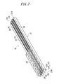
- FIG. 7 is a perspective view of the whole electrochemical sensor 4 according to the first modified example of the first working example.
- the electrode 22 is provided on the substrate 21.
- the substrate 21 is formed with plural lines of grooves 27A and plural lines of grooves 27B.
- the grooves 27A of the substrate 21 are formed in the direction of arranging the electrode 22 of the substrate 21 (the direction of providing the electrode 22 on the substrate 21).
- the direction in which the electrode 22 is provided on the substrate 21 is coincident with the longitudinal direction of the substrate 21.
- the grooves 27B of the substrate 21 are formed in the widthwise direction of the substrate 21.
- the grooves 27B of the substrate 21 include a groove formed extending from an end portion 21C of the substrate 21 to the groove 27A of the substrate 21, and a groove which connects the grooves 27A of the substrate 21 to each other.
- FIG. 7 depicts an example of providing the single working electrode 22A and the single counter electrode 22B on the substrate 21.
- the present embodiment is not, however, limited to this arrangement, and the plurality of electrodes 22 may also be provided on the substrate 21.
- the plurality of working electrodes 22A may be provided on the substrate 21, and the plurality of counter electrodes 22B may also be provided on the substrate 21.
- a position in which the groove 27B is formed extending from the end portion 21C of the substrate 21 to the groove 27A of the substrate 21 may be an arbitrary position if being the position of a portion inserted into the skin 6.
- the grooves 27B may be formed so as to extend from an end portion 21D of the substrate 21 to the groove 27A of the substrate 21.
- the grooves 27A of the substrate 21 are formed up to the near side of the end portion 21B of the substrate 21.
- the electrode 22 is provided on the near side of the end portion 21B of the substrate 21, and therefore the grooves 27A of the substrate 21 are formed up to the near side of the end portion 21B of the substrate 21.
- the present embodiment is not, however, limited to this formation, and the grooves 27A of the substrate 21 may be formed in the vicinity of the electrode 22 on the substrate 21. That is, the positions in which to form the grooves 27A in the substrate 21 are changed corresponding to the position of the electrode 22 on the substrate 21.
- the external layer film 25 is provided on the substrate 21 so as to cover the working electrode 22A, the counter electrode 22B, the grooves 27A of the substrate 21 and the grooves 27B of the substrate 21.
- the contrivance in the first modified example of the first working example is that the external layer film 25 is embedded in neither the interior of the groove 27A of the substrate 21 nor the interior of the groove 27B of the substrate 21, however, without being confined to this contrivance, the external layer film 25 may be embedded in the interior of the groove 27A of the substrate 21 and in the interior of the groove 27B of the substrate 21.
- the upper portion of the groove 27B of the substrate 21 is not covered by the external layer film 25. Namely, there is exposed the upper portion of the groove 27B at the peripheral portion of the end portion 21C of the substrate 21.
- the analyte within the skin 6 contacts the groove 27B of the substrate 21.
- the upper portion of the groove 27B of the substrate 21 is not covered by the external layer film 25 at the peripheral portion of the end portion 21C of the substrate 21, and hence the analyte contacts the groove 27B of the substrate 21 from the direction of the side surface or the upper surface of the substrate 21.
- the analyte coming into contact with the grooves 27B of the substrate 21 is introduced into the interiors of the grooves 27B of the substrate 21 by dint of the capillarity.
- the analyte introduced into the interiors of the grooves 27B of the substrate 21 advances through the interiors of the grooves 27B of the substrate 21 by dint of the capillarity in the widthwise direction of the substrate 21.
- the analyte contacts the lower surface of the external layer film 25 provided upwardly of the grooves 27B of the substrate 21.
- the analyte contacting the lower surface of the external layer film 25 permeates the interior of the external layer film 25 and is thus supplied to the surface of the working electrode 22A.
- the analyte advancing through the interiors of the grooves 27B of the substrate 21 in the widthwise direction of the substrate 21 is introduced into the interiors of the grooves 27A of the substrate 21.
- the analyte introduced into the interiors of the grooves 27A of the substrate 21 advances through the interiors of the grooves 27A of the substrate 21 by dint of the capillarity in the longitudinal direction of the substrate 21.
- the analyte advances through the interiors of the grooves 27A of the substrate 21 up to the near side of the end portion 21B of the substrate 21, and comes into contact with the lower surface of the external layer film 25 provided upwardly of the grooves 27A of the substrate 21.
- the analyte coming into contact with the lower surface of the external layer film 25 permeates the interior of the external layer film 25 and is thus supplied to the surface of the working electrode 22A.
- the analyte advances through the interiors of the grooves 27A of the substrate 21 and the interiors of the grooves 27B of the substrate 21 and is thus supplied to the surface of the working electrode 22A.
- the analyte advances through the interiors of the grooves 27A of the substrate 21 and the interiors of the grooves 27B of the substrate 21 and is thus supplied to the surface of the working electrode 22A.
- a widthwise length and a depth of each of the grooves 27A of the substrate 21 are determined so that the analyte is introduced into the interiors of the grooves 27A of the substrate 21 by dint of the capillarity and that the analyte advances through the interiors of the grooves 27A of the substrate 21 by dint of the capillarity.
- the widthwise length of each of the grooves 27A of the substrate 21 is equal to or larger than, e.g., 0.05 mm but equal to or smaller than 3 mm, preferably equal to or larger than 0.1 mm but equal to or smaller than 3 mm, and more preferably equal to or larger than, e.g., 0.1 mm but equal to or smaller than 1 mm.
- each of the grooves 27A of the substrate 21 is equal to or larger than, e.g., 50 ⁇ m but equal to or smaller than 200 ⁇ m and preferably equal to or larger than 75 ⁇ m but equal to or smaller than 150 ⁇ m. Furthermore, a widthwise length and a depth of each of the grooves 27B of the substrate 21 are determined so that the analyte is introduced into the interiors of the grooves 27B of the substrate 21 by dint of the capillarity and that the analyte advances through the interiors of the grooves 27B of the substrate 21 by dint of the capillarity.
- each of the grooves 27B of the substrate 21 is equal to or larger than, e.g., 0.05 mm but equal to or smaller than 3 mm, preferably equal to or larger than 0.1 mm but equal to or smaller than 3 mm, and more preferably equal to or larger than, e.g., 0.1 mm but equal to or smaller than 1 mm.
- the depth of each of the grooves 27B of the substrate 21 is equal to or larger than, e.g., 50 ⁇ m but equal to or smaller than 200 ⁇ m and preferably equal to or larger than 75 ⁇ m but equal to or smaller than 150 ⁇ m.
- each of the grooves 27A and 27B of the substrate 21 undergoes the hydrophilization process.
- a variety of known methods can be adopted as a method of the hydrophilization process.
- the hydrophilization process may be executed by using, e.g., the VUV (vacuum ultraviolet rays) process, the plasma exposure process, the surface active agent coating process, etc. Further, the hydrophilization process may also be carried out by using the same method as the method described in Japanese Unexamined Patent Publication No. 2010-532269 .
- each of the grooves 27A and 27B of the substrate 21 is subjected to the hydrophilization process, thereby accelerating a degree of how much the interiors of the grooves 27A and 27B of the substrate 21 get wetted with the analyte and accelerating the advancement of the analyte through the interiors of the grooves 27A and 27B of the substrate 21.
- the hydrophilization process over the internal surfaces of the grooves 27A and 27B of the substrate 21 is performed so that a contact angle with the analyte is smaller than, e.g., 30 degrees.
- the contact angle with the analyte may be equal to or larger than 30 degrees.
- the VUV process is conducted by use of, e.g., the ultraviolet rays (the excimer laser etc) having the wavelength of 172 nm with the intensity of 2. 3 mW/cm 2 (in a case where a distance between the light source and the substrate 21 is 4 mm) for irradiation time that is equal to or longer than several dozens of seconds but equal to shorter than 30 minutes.
- the VUV process may use, without being limited to the ultraviolet rays having the wavelength of 172 nm, the ultraviolet rays having other wavelengths.
- the first modified example of the first working example demonstrates the instance in which the upper portion of the substrate 21 is not covered by the external layer film 25 at the peripheral portion of the end portion 21C of the substrate 21.
- the present embodiment is not, however, limited to this cover mode, and the entire upper portion of the groove 27B of the substrate 21 may be covered by the external layer film 25 at the peripheral portion of the end portion 21C of the substrate 21. That is, the upper portion of the groove 27B of the substrate 21 may not be exposed at the peripheral portion of the end portion 21C of the substrate 21.
- the first modified example of the first working example demonstrates the instance in which the electrode 22 is provided, on the substrate 21, adjacent to the grooves 27A of the substrate 21.
- the present embodiment is not, however, limited to this configuration, and the electrode 22 may be provided upwardly of the groove 27A of the substrate 21.
- the electrode 22 may be provided on the substrate 21 so that at least a part of the electrode 22 is positioned upwardly of the groove 27A of the substrate 21.
- the first modified example of the first working example demonstrates the instance in which the plural lines of grooves 27A are formed in the substrate 21.
- the present embodiment is not, however, limited to this formation, and only one line of groove 27A may also be formed in the substrate 21.
- the groove 27A of the substrate 21 may be positioned between the working electrode 22A and the counter electrode 22B.
- the first modified example of the first working example demonstrates the instance in which the plural lines of grooves 27B are formed in the substrate 21.
- the present embodiment is not, however, limited to this formation, and only one line of groove 27B may also be formed in the substrate 21.
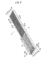
- FIG. 8 is a perspective view of the whole electrochemical sensor 4 according to the second modified example of the first working example.
- the electrode 22 is provided on the substrate 21.
- the substrate 21 is formed with plural lines of grooves 28.
- the grooves 28 of the substrate 21 are formed in the direction of arranging the electrode 22 of the substrate 21 (the direction of providing the electrode 22 on the substrate 21).
- the direction in which the electrode 22 is provided on the substrate 21 is coincident with the longitudinal direction of the substrate 21.
- the grooves 28 of the substrate 21 are formed up to the near side of the end portion 21B of the substrate 21.
- the external layer film 25 is provided on the substrate 21 so as to cover the working electrode 22A, the counter electrode 22B and a part of the grooves 28 of the substrate 21.
- the contrivance in the second modified example of the first working example is that the external layer film 25 is not embedded in the interiors of the grooves 28 of the substrate 21, however, without being confined to this contrivance, the external layer film 25 may be embedded in the interiors of the grooves 28 of the substrate 21.
- the upper portion of the groove 28 of the substrate 21 is not covered by the external layer film 25. Namely, the upper portion of a part of the groove 28 of the substrate 21 is exposed.
- the analyte within the skin 6 contacts the part of the groove 28 of the substrate 21.
- the upper portion of the part of the groove 28 of the substrate 21 is not covered by the external layer film 25, and therefore the analyte contacts the groove 28 of the substrate 21 from the direction of the upper surface of the substrate 21.
- the analyte coming into contact with the grooves 28 of the substrate 21 is introduced into the interiors of the grooves 28 of the substrate 21 by dint of the capillarity.
- the analyte introduced into the interiors of the grooves 28 of the substrate 21 advances through the interiors of the grooves 28 of the substrate 21 by dint of the capillarity in the longitudinal direction of the substrate 21.
- the analyte advancing through the interiors of the grooves 28 of the substrate 21 in the longitudinal direction of the substrate 21 contacts the lower surface of the external layer film 25 provided upwardly of the grooves 28 of the substrate 21.
- the analyte contacting the lower surface of the external layer film 25 permeates the interior of the external layer film 25 and is thus supplied to the surface of the working electrode 22A.
- the analyte is introduced into the interiors of the grooves 28 of the substrate 21 and is thereby supplied to the surface of the working electrode 22A.
- the analyte does not exist in the periphery of the external layer film 25 but exists only in the portion where the upper portions of the grooves 28 of the substrate 21 are not covered by the external layer film 25, even in which case the analyte is introduced into the interiors of the grooves 28 of the substrate 21 and is thereby supplied to the surface of the working electrode 22A.
- a widthwise length and a depth of each of the grooves 28 of the substrate 21 are determined so that the analyte is introduced into the interiors of the grooves 28 of the substrate 21 by dint of the capillarity and that the analyte advances through the interiors of the grooves 28 of the substrate 21 by dint of the capillarity.
- the widthwise length of each of the grooves 28 of the substrate 21 is equal to or larger than, e.g., 0.05 mm but equal to or smaller than 3 mm, preferably equal to or larger than 0.1 mm but equal to or smaller than 3 mm, and more preferably equal to or larger than, e.g., 0.1 mm but equal to or smaller than 1 mm.
- each of the grooves 28 of the substrate 21 is equal to or larger than, e.g., 50 ⁇ m but equal to or smaller than 200 ⁇ m and preferably equal to or larger than 75 ⁇ m but equal to or smaller than 150 ⁇ m.
- each of the grooves 28 of the substrate 21 undergoes the hydrophilization process.
- a variety of known methods can be adopted as a method of the hydrophilization process.
- the hydrophilization process may be executed by using, e.g., the VUV (vacuum ultraviolet rays) process, the plasma exposure process, the surface active agent coating process, etc. Further, the hydrophilization process may also be carried out by using the same method as the method described in Japanese Unexamined Patent Publication No. 2010-532269 .
- each of the grooves 28 of the substrate 21 is subjected to the hydrophilization process, thereby accelerating a degree of how much the interiors of the grooves 28 of the substrate 21 get wetted with the analyte and accelerating the advancement of the analyte through the interiors of the grooves 28 of the substrate 21. It is preferable that the hydrophilization process over the internal surfaces of the grooves 28 of the substrate 21 is performed so that a contact angle with the analyte is smaller than, e.g., 30 degrees.
- the contact angle with the analyte may be equal to or larger than 30 degrees.
- the VUV process is conducted by use of, e.g., the ultraviolet rays (the excimer laser etc) having the wavelength of 172 nm with the intensity of 2.3 mW/cm 2 (in a case where a distance between the light source and the substrate 21 is 4 mm) for irradiation time that is equal to or longer than several dozens of seconds but equal to shorter than 30 minutes.
- the VUV process may use, without being limited to the ultraviolet rays having the wavelength of 172 nm, the ultraviolet rays having other wavelengths.
- the second modified example of the first working example demonstrates the instance in which the electrode 22 is provided, on the substrate 21, adjacent to the grooves 28 of the substrate 21.
- the present embodiment is not, however, limited to this configuration, and the electrode 22 may be provided upwardly of the groove 28 of the substrate 21.
- the electrode 22 may be provided on the substrate 21 so that at least a part of the electrode 22 is positioned upwardly of the groove 28 of the substrate 21.
- the second modified example of the first working example demonstrates the instance in which the plural lines of grooves 28 are formed in the substrate 21.
- the present embodiment is not, however, limited to this formation, and only one line of groove 28 may also be formed in the substrate 21.
- the groove 28 of the substrate 21 may be positioned between the working electrode 22A and the counter electrode 22B.
- FIG. 9 is a perspective view of the whole electrochemical sensor 4 according to the third modified example of the first working example.
- the electrode 22 is provided on the substrate 21.
- the substrate 21 is formed with plural lines of grooves 29.
- the grooves 29 of the substrate 21 are formed in the direction of arranging the electrode 22 of the substrate 21 (the direction of providing the electrode 22 on the substrate 21).
- the direction in which the electrode 22 is provided on the substrate 21 is coincident with the widthwise direction of the substrate 21.
- the groove 29 of the substrate 21 is formed in the substrate 21 in a way that intersects the electrode 22 on the substrate 21.
- the electrode 22 is provided on the substrate 21 so that a part of the electrode 22 is positioned upwardly of the groove 29 of the substrate 21.
- the working electrode 22A is provided on the substrate 21 so that a part of the working electrode 22A is positioned upwardly of the groove 29 of the substrate 21, and the counter electrode 22B is provided on the substrate 21 so that a part of the counter electrode 22B is positioned upwardly of the groove 29 of the substrate 21.
- FIG. 9 depicts an example of providing the single working electrode 22A and the single counter electrode 22B on the substrate 21.
- the present embodiment is not, however, limited to this arrangement, and the plurality of electrodes 22 may also be provided on the substrate 21. Further, the plurality of working electrodes 22A may be provided on the substrate 21, and the plurality of counter electrodes 22B may also be provided on the substrate 21.
- the external layer film 25 is provided on the substrate 21 so as to cover the working electrode 22A, the counter electrode 22B and the grooves 29 of the substrate 21.
- the contrivance in the third modified example of the first working example is that the external layer film 25 is not embedded in the interior of the groove 29 of the substrate 21, however, without being confined to this contrivance, the external layer film 25 may be embedded in the interior of the groove 29 of the substrate 21.
- the upper portion of the groove 29 of the substrate 21 is not covered by the external layer film 25. Namely, the upper portion of the groove 29 at the peripheral portion of the end portion 21C of the substrate 21 is exposed.
- the analyte within the skin 6 contacts the groove 29 of the substrate 21.
- the upper portion of the groove 29 of the substrate 21 is not covered by the external layer film 25, and therefore the analyte contacts the groove 29 of the substrate 21 from the direction of the side surface or the upper surface of the substrate 21.
- the analyte coming into contact with the grooves 29 of the substrate 21 is introduced into the interiors of the grooves 29 of the substrate 21 by dint of the capillarity.
- the analyte introduced into the interiors of the grooves 29 of the substrate 21 advances through the interiors of the grooves 29 of the substrate 21 by dint of the capillarity in the widthwise direction of the substrate 21.
- the analyte contacts the lower surface of the external layer film 25 provided upwardly of the grooves 29 of the substrate 21.
- the analyte contacting the lower surface of the external layer film 25 permeates the interior of the external layer film 25 and is thus supplied to the surface of the working electrode 22A.
- the analyte advancing through the interiors of the grooves 29 of the substrate 21 in the widthwise direction of the substrate 21 comes into contact with the working electrode 22A provided upwardly of the grooves 29 of the substrate 21 and is thus supplied to the surface of the working electrode 22A.
- the analyte advances through the interiors of the grooves 29 of the substrate 21 and is thereby supplied to the surface of the working electrode 22A.
- the analyte advances through the interiors of the grooves 29 of the substrate 21 and is thus supplied to the surface of the working electrode 22A.
- a widthwise length and a depth of each of the grooves 29 of the substrate 21 are determined so that the analyte is introduced into the interiors of the grooves 29 of the substrate 21 by dint of the capillarity and that the analyte advances through the interiors of the grooves 29 of the substrate 21 by dint of the capillarity.
- the widthwise length of each of the grooves 29 of the substrate 21 is equal to or larger than, e.g., 0.05 mm but equal to or smaller than 3 mm, preferably equal to or larger than 0.1 mm but equal to or smaller than 3 mm, and more preferably equal to or larger than, e.g., 0.1 mm but equal to or smaller than 1 mm.
- each of the grooves 29 of the substrate 21 is equal to or larger than, e.g., 50 ⁇ m but equal to or smaller than 200 ⁇ m and preferably equal to or larger than 75 ⁇ m but equal to or smaller than 150 ⁇ m.
- each of the grooves 29 of the substrate 21 undergoes the hydrophilization process.
- a variety of known methods can be adopted as a method of the hydrophilization process.
- the hydrophilization process may be executed by using, e.g., the VUV (vacuum ultraviolet rays) process, the plasma exposure process, the surface active agent coating process, etc. Further, the hydrophilization process may also be carried out by using the same method as the method described in Japanese Unexamined Patent Publication No. 2010-532269 .
- each of the grooves 29 of the substrate 21 is subjected to the hydrophilization process, thereby accelerating a degree of how much the interiors of the grooves 29 of the substrate 21 get wetted with the analyte and accelerating the advancement of the analyte through the interiors of the grooves 29 of the substrate 21. It is preferable that the hydrophilization process over the internal surfaces of the grooves 29 of the substrate 21 is performed so that a contact angle with the analyte is smaller than, e.g., 30 degrees.
- the contact angle with the analyte may be equal to or larger than 30 degrees.
- the VUV process is conducted by use of, e.g., the ultraviolet rays (the excimer laser etc) having the wavelength of 172 nm with the intensity of 2. 3 mW/cm 2 (in a case where a distance between the light source and the substrate 21 is 4 mm) for irradiation time that is equal to or longer than several dozens of seconds but equal to shorter than 30 minutes.
- the VUV process may use, without being limited to the ultraviolet rays having the wavelength of 172 nm, the ultraviolet rays having other wavelengths.
- the third modified example of the first working example demonstrates the instance in which the upper portion of the substrate 21 is not covered by the external layer film 25 at the peripheral portion of the end portion 21C of the substrate 21.
- the present embodiment is not, however, limited to this cover mode, and the entire upper portion of the groove 29 of the substrate 21 may be covered by the external layer film 25 at the peripheral portion of the end portion 21C of the substrate 21. That is, the upper portion of the groove 29 of the substrate 21 may not be exposed at the peripheral portion of the end portion 21C of the substrate 21.
- the third modified example of the first working example demonstrates the instance in which the electrode 22 is provided, on the substrate 21, adjacent to the grooves 29 of the substrate 21.
- the present embodiment is not, however, limited to this configuration, and the electrode 22 may be provided upwardly of the groove 29 of the substrate 21.
- the electrode 22 may be provided on the substrate 21 so that at least a part of the electrode 22 is positioned upwardly of the groove 29 of the substrate 21.
- the third modified example of the first working example demonstrates the instance of forming the plural lines of grooves 29 in the substrate 21.
- the present embodiment is not, however, limited to this formation, and only one line of groove 29 may be formed in the substrate 21.
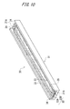
- FIG. 10 is a perspective view of a whole electrochemical sensor 30 according to the second working example.
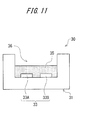
- FIG. 11 is a sectional view of the electrochemical sensor 30 according to the second working example.
- the electrochemical sensor 30 is inserted into the base plate 11 of the composition continuous measuring apparatus 1 illustrated in FIG. 1 , and the end portion of the electrochemical sensor 30 is fixed to the base plate 11.
- the electrochemical sensor 30 includes a substrate 31, an electrode 32, lead wires 33, a terminal 34 and an external layer film 35.
- the substrate 31 has an insulating property and flexibility, and supports the electrode 32.
- a portion including an end portion 31A of the substrate 31 is housed inside the housing 2.
- a portion including an end portion 31B, opposite to the end portion 31A, of the substrate 31 is inserted into the skin 6.
- the end portion 31B of the substrate 31 may take an acute shape. The shape of the end portion 31B of the substrate 31 is set acute, thereby enabling the insertion of the electrochemical sensor 30 into the skin 6 to be facilitated and a pain of an examinee undergoing the insertion of the electrochemical sensor 30 to be relieved.
- the substrate 31 can involve using a material exhibiting biocompatibility and the insulating property.
- resins such as polypropylene, polyimide, polyethylene terephthalate, polyether ether ketone and polyethylene naphthalate can be used for the substrate 31.
- the substrate 31 is equal to or larger than, e.g., 2 mm and preferably 5 mm but equal to or smaller than 50 mm and preferably 30 mm long in a longitudinal direction.
- the substrate 31 is equal to or larger than, e.g., 0.05 mm and preferably 0.1 mm but equal to or smaller than 5 mm and preferably 3 mm long in a widthwise direction.
- the longitudinal direction of the substrate 31 is defined as a direction extending from the end portion 31B of the substrate 31 toward the end portion 31A of the substrate 31 (the direction in which the substrate 31 is housed inside the housing 2) or a direction extending from the end portion 31A of the substrate 31 toward the end portion 31B of the substrate 31 (the direction in which the substrate 31 is inserted into the skin 6).
- the widthwise direction of the substrate 31 is defined as a direction orthogonal to the longitudinal direction of the substrate 31.
- the substrate 31 is formed with a groove 36 extending in the longitudinal direction of the substrate 31.
- the groove 36 of the substrate 31 is formed extending from an end portion 31B of the substrate 31 to an end portion 31A of the substrate 31.
- the end portion 31B of the substrate 31 and a peripheral portion to the end portion 31B are referred to also as a leading end portion of the substrate 31.
- the groove 36 of the substrate 31 is formed in a concave shape.
- the concave shape includes a quadrangular shape, a semicircular shape, a semielliptical shape, a pyramid shape, etc.
- a resist pattern is formed on the substrate 31 by, e.g., a photolithography technology, and the substrate 31 is etched with the resist pattern serving as a mask, whereby the groove 36 can be formed in the substrate 31. Further, the groove 36 can be formed in the substrate 31 also by etching based on laser beam machining.
- the electrode 32 can be formed by, e.g., vapor deposition, sputtering, printing (screen printing, gravure printing) or transfer printing, etc.
- the electrode 32 includes a working electrode 32A and a counter electrode 32B.
- the working electrode 32A is an electrode element for transferring and receiving electrons to and from the specified composition in the analyte.
- the counter electrode 32B is used for applying the voltage together with the working electrode 32A.
- FIGS. 10 and 11 illustrate an example in which a single working electrode 32A and a single counter electrode 32B are provided in the interior of the groove 36 of the substrate 31.
- the present embodiment is not, however, limited to this configuration, and a plurality of electrodes 32 may be provided in the interior of the groove 36 of the substrate 31.
- a plurality of working electrodes 32A may be provided in the interior of the groove 36 of the substrate 31, and a plurality of counter electrodes 32B may also be provided in the interior of the groove 36 of the substrate 31.
- FIG. 12 is a perspective view of the whole electrochemical sensor 30 in the case of providing the plurality of working electrodes 32A and the plurality of counter electrodes 32B in the interior of the groove 36 of the substrate 31.
- FIG. 13 is a sectional view in the case of providing the plurality of working electrodes 32A and the plurality of counter electrodes 32B in the interior of the groove 36 of the substrate 31.
- the plurality of working electrodes 32A is provided on the substrate 31, thereby making it possible to continue measuring the concentration of the specified composition in the analyte even if the malfunction such as a failure occurs in one working electrode 32A.
- the plurality of counter electrodes 32B is provided on the substrate 31, thereby making it possible to continue measuring the concentration of the specified composition in the analyte even if the malfunction such as the failure occurs in one counter electrode 32B.
- One ends of the lead wires 33 are connected to the working electrode 32A and the counter electrode 32B, and terminals 34 are connected to the other ends of the lead wires 33.
- the terminal 34 is brought into contact with the terminal 12 of the circuit board 3.
- a reagent enzyme is formed on the surface of the working electrode 32A.
- the reagent enzyme can involve using glucose oxidase (GOD) or glucose dehydrogenase (GDH).
- GOD glucose oxidase
- GDH glucose dehydrogenase
- a method of immobilizing the reagent enzyme can adopt a variety of known methods such as a method of utilizing MPC polymer in which a silane coupling agent is introduced into polymeric gel, high polymer such as polyacrylamide and phosphorus and phospholipid polymer, or a protein film.
- the external layer film 35 may contain the reagent enzyme in place of forming the reagent enzyme on the surface of the working electrode 32A.
- the external layer film 35 is structured to allow the analyte to enters inside the film itself. Namely, when the analyte contacts the external layer film 35, the analyte permeates the interior of the external layer film 35. The analyte permeating the interior of the external layer film 35 reaches the surface of the working electrode 32A. Thus, the outside of the external layer film 35 conducts to the working electrode 32A via the external layer film 35.
- the material exhibiting the biocompatibility can be employed for the external layer film 35.
- the external layer film 35 can involve using, e.g., polyurethane, silicon-based polymer (polysiloxane), cellulose acetate, hydrogel, polyvinyl alcohol, HEMA (hydroxyethyl methacrylate), and copolymer containing these substances.
- the external layer film 35 can be formed by, e.g., spin coating, dip coating or drop coating, etc.
- the external layer film 35 is provided in the interior of the groove 36 of the substrate 31 so as to cover the electrode 32.
- the external layer film 35 is provided so as to cover the electrode 32, and therefore, when the electrochemical sensor 30 is inserted into the skin 6, it follows that the electrode 32 does not directly contact the skin 6.
- the external layer film 35 functions also as a protection film for protecting the electrode 32.
- the analyte within the skin 6 contacts the groove 36 of the substrate 31.
- the analyte coming into contact with the groove 36 of the substrate 31 is introduced into the interior of the groove 36 of the substrate 31 by dint of the capillarity.
- the analyte introduced into the interior of the groove 36 of the substrate 31 permeates the interior of the external layer film 35.
- the analyte permeates the interior of the external layer film 35 and reaches the surface of the working electrode 32A, at which time the reagent enzyme formed on the surface of the working electrode 32A reacts on the analyte.
- the working electrode 32A and the counter electrode 32B apply the voltage to the reagent enzyme, thereby transferring and receiving the electrons between the specified composition contained in the analyte and the working electrode 32A.
- the reagent enzyme contained by the external layer film 35 reacts on the analyte, and the working electrode 32A and the counter electrode 32B apply the voltage to the reagent enzyme, thereby transferring and receiving the electrons between the specified composition contained in the analyte and the working electrode 32A.
- the electrode 32 and the external layer film 35 are formed in the interior of the groove 36 of the substrate 31.
- the analyte is introduced into the interior of the groove 36 of the substrate 31 by dint of the capillarity.
- the analyte introduced into the interior of the groove 36 of the substrate 31 contacts the upper surface of the external layer film 35.
- the analyte brought into contact with the upper surface of the external layer film 35 permeates the interior of the external layer film 35.
- the external layer film 35 is provided in the interior of the groove 36 of the substrate 31 so as to cover the working electrode 32A, the analyte permeating the interior of the external layer film 35 comes to a state of existing in the periphery of the working electrode 32A, and consequently the deletion of the analyte on the surface of the working electrode 32A is restrained.
- the substrate 31 is formed with the groove 36, and the electrode 32 and the external layer film 35 are provided in the interior of the groove 36 of the substrate 31, thereby making it feasible to increase a quantity of supply of the analyte to the surface of the working electrode 32A.
- the analyte Because of the analyte being introduced into the interior of the groove 36 of the substrate 31 by dint of the capillarity, the analyte can be early supplied to the surface of the working electrode 32A, and it is possible to reduce the period of time till the surface of the working electrode 32A gets wetted with the analyte. As a result, it is possible to reduce the period of time of the initial operation required for stably measuring the concentration of the specified composition in the analyte.
- the analyte introduced into the interior of the groove 36 of the substrate 31 advances through the interior of the groove 36 of the substrate 31 by dint of the capillarity and gets accumulated in the interior of the groove 36 of the substrate 31. Even when the quantity of the analyte in the periphery of the electrochemical sensor 30 inserted into the skin 6 decreases, if kept in the state where the analyte remains in the interior of the groove 36 of the substrate 31, it is feasible to restrain a risk against the depletion of the analyte on the surface of the working electrode 32A.
- the depletion of the interstitial fluid on the surface of the working electrode 32A can be restrained by reserving the interstitial fluid in the interior of the groove 36 of the substrate 31.
- a widthwise length and a depth of the groove 36 of the substrate 31 are determined so that the analyte is introduced into the interior of the groove 36 of the substrate 31 by dint of the capillarity and that the analyte advances through the interior of the groove 36 of the substrate 31 by dint of the capillarity.
- the widthwise length of the groove 36 of the substrate 31 is equal to or larger than, e.g., 0.05 mm but equal to or smaller than 3 mm, preferably equal to or larger than 0.1 mm but equal to or smaller than 3 mm, and more preferably equal to or larger than, e.g., 0.1 mm but equal to or smaller than 1 mm.
- the depth of the groove 36 of the substrate 31 is equal to or larger than, e.g., 50 ⁇ m but equal to or smaller than 200 ⁇ m and preferably equal to or larger than 75 ⁇ m but equal to or smaller than 150 ⁇ m.
- an internal surface of the groove 36 of the substrate 31 undergoes a hydrophilization process.
- a variety of known methods can be adopted as a method of the hydrophilization process.
- the hydrophilization process may be executed by using, e.g., VUV (vacuum ultraviolet rays) process, a plasma exposure process, a surface active agent coating process, etc. Further, the hydrophilization process may also be carried out by using the same method as the method described in Japanese Unexamined Patent Publication No. 2010-532269 .
- the internal surface of the groove 36 of the substrate 31 is subjected to the hydrophilization process, thereby accelerating a degree of how much the interior of the groove 36 of the substrate 31 get wetted with the analyte and accelerating the advancement of the analyte through the interior of the groove 36 of the substrate 31. It is preferable that the hydrophilization process over the internal surface of the groove 36 of the substrate 31 is performed so that a contact angle with the analyte is smaller than, e.g., 30 degrees. If the internal surface of the groove 36 of the substrate 31 is hydrophilized in such an extent as to allow the analyte to advance through the interior of the groove 36 of the substrate 31, however, the contact angle with the analyte may be equal to or larger than 30 degrees.
- the VUV process is conducted by use of, e.g., the ultraviolet rays (an excimer laser etc) having a wavelength of 172 nm with an intensity of 2.3 mW/cm 2 (in a case where a distance between the light source and the substrate 31 is 4 mm) for irradiation time that is equal to or longer than several dozens of seconds but equal to shorter than 30 minutes.
- the VUV process may use, without being limited to the ultraviolet rays having the wavelength of 172 nm, the ultraviolet rays having other wavelengths.
- the second working example demonstrates the instance of forming the groove 36 in the substrate 31 in a way that extends from the end portion 31B of the substrate 31 to the end portion 31A of the substrate 31.
- the present embodiment is not, however, limited to this formation, and the groove 36 may be formed in the substrate 31 so as to extend at a predetermined distance from the end portion 31B of the substrate 31 in the longitudinal direction of the substrate 31.
- the groove 36 may also be formed in a portion of the substrate 31, which is inserted into the skin 6.
- FIG. 14 is a perspective view of the whole electrochemical sensor 30 according to the first modified example of the second working example.
- a projection 37A and a projection 37B are formed on the substrate 31 in the longitudinal direction of the substrate 31.
- a groove 38 is formed in the substrate 31 between the projection 37A and the projection 37B.
- the groove 38 of the substrate 31 is formed in a concave shape.
- the concave shape includes a quadrangular shape, a semicircular shape, a semielliptical shape, a pyramid shape, etc.
- a resist pattern is formed on the substrate 31 by, e.g., the photolithography technology, and the substrate 31 is etched with the resist pattern serving as a mask, whereby the substrate 31 can be formed with the projection 37A, the projection 37B and the groove 38. Moreover, the substrate 31 can be formed with the projection 37A, the projection 37B and the groove 38 also by etching based on the laser beam machining.
- the groove 38 may be formed in the substrate 31 in a manner that extends from the end portion 31B of the substrate 31 in the longitudinal direction of the substrate 31. That is, the substrate 31 is provided with the projection 37A and the projection 37B so that the projection 37A and the projection 37B abut on the end portion 31B of the substrate 31, and the groove 38 may be formed between the projection 37A and the projection 37B.
- the groove 38 may be formed in the substrate 31 in a manner that extends from the end portion 31A of the substrate 31 in the longitudinal direction of the substrate 31. That is, the substrate 31 is provided with the projection 37A and the projection 37B so that the projection 37A and the projection 37B abut on the end portion 31A of the substrate 31, and the groove 38 may be formed between the projection 37A and the projection 37B.
- the groove 38 may be formed in the substrate 31 in a way that extends from the end portion 31B of the substrate 31 up to the end portion 31A of the substrate 31 in the longitudinal direction of the substrate 31.
- the substrate 31 is provided with the projection 37A and the projection 37B so that the projection 37A and the projection 37B abut on the end portion 31B of the substrate 31 and that the projection 37A and the projection 37B abut on the end portion 31A of the substrate 31, and the groove 38 may be formed between the projection 37A and the projection 37B.
- FIG. 14 illustrates an example in which a single working electrode 32A and a single counter electrode 32B are provided in the interior of the groove 38 of the substrate 31.
- the present embodiment is not, however, limited to this configuration, and a plurality of electrodes 32 may be provided in the interior of the groove 38 of the substrate 31.
- a plurality of working electrodes 32A may be provided in the interior of the groove 38 of the substrate 31, and a plurality of counter electrodes 32B may also be provided in the interior of the groove 38 of the substrate 31.
- the analyte within the skin 6 contacts the groove 38 of the substrate 31.
- the analyte coming into contact with the groove 38 of the substrate 31 is introduced into the interior of the groove 38 of the substrate 31 by dint of the capillarity.
- the analyte introduced into the interior of the groove 38 of the substrate 31 permeates the interior of the external layer film 35 and is thus supplied to the surface of the working electrode 32A.
- a widthwise length and a depth of the groove 38 of the substrate 31 are determined so that the analyte is introduced into the interior of the groove 38 of the substrate 31 by dint of the capillarity and that the analyte advances through the interior of the groove 38 of the substrate 31 by dint of the capillarity.
- the widthwise length of the groove 38 of the substrate 31 is equal to or larger than, e.g., 0.05 mm but equal to or smaller than 3 mm, preferably equal to or larger than 0.1 mm but equal to or smaller than 3 mm, and more preferably equal to or larger than, e.g., 0.1 mm but equal to or smaller than 1 mm.
- the depth of the groove 38 of the substrate 31 is equal to or larger than, e.g., 50 ⁇ m but equal to or smaller than 200 ⁇ m and preferably equal to or larger than 75 ⁇ m but equal to or smaller than 150 ⁇ m.
- an internal surface of the groove 38 of the substrate 31 undergoes a hydrophilization process.
- a variety of known methods can be adopted as a method of the hydrophilization process.
- the hydrophilization process may be executed by using, e.g., VUV (vacuum ultraviolet rays) process, a plasma exposure process, a surface active agent coating process, etc. Further, the hydrophilization process may also be carried out by using the same method as the method described in Japanese Unexamined Patent Publication No. 2010-532269 .
- the internal surface of the groove 38 of the substrate 31 is subjected to the hydrophilization process, thereby accelerating a degree of how much the interior of the groove 38 of the substrate 31 get wetted with the analyte and accelerating the advancement of the analyte through the interior of the groove 38 of the substrate 31. It is preferable that the hydrophilization process over the internal surface of the groove 38 of the substrate 31 is performed so that a contact angle with the analyte is smaller than, e.g., 30 degrees. If the internal surface of the groove 38 of the substrate 31 is hydrophilized in such an extent as to allow the analyte to advance through the interior of the groove 38 of the substrate 31, however, the contact angle with the analyte may be equal to or larger than 30 degrees.
- the VUV process is conducted by use of, e.g., the ultraviolet rays (an excimer laser etc) having a wavelength of 172 nm with an intensity of 2.3 mW/cm 2 (in a case where a distance between the light source and the substrate 31 is 4 mm) for irradiation time that is equal to or longer than several dozens of seconds but equal to shorter than 30 minutes.
- the VUV process may use, without being limited to the ultraviolet rays having the wavelength of 172 nm, the ultraviolet rays having other wavelengths.
- FIG. 15 is a perspective view of the whole electrochemical sensor 30 according to the second modified example of the second working example.
- a projection 39A and a projection 39B are formed on the substrate 31 in the widthwise direction of the substrate 31. Further, a groove 40 is formed in the substrate 31 between the projection 39A and the projection 39B.
- the groove 40 of the substrate 31 is formed in a concave shape.
- the concave shape includes a quadrangular shape, a semicircular shape, a semielliptical shape, a pyramid shape, etc.
- a resist pattern is formed on the substrate 31 by, e.g., the photolithography technology, and the substrate 31 is etched with the resist pattern serving as a mask, whereby the substrate 31 can be formed with the projection 39A, the projection 39B and the groove 40. Moreover, the substrate 31 can be formed with the projection 39A, the projection 39B and the groove 40 also by etching based on the laser beam machining.
- the groove 40 may be formed in the substrate 31 in a manner that extends from the end portion 31C of the substrate 31 in the widthwise direction of the substrate 31. That is, the substrate 31 is provided with the projection 39A and the projection 39B so that the projection 39A and the projection 39B abut on the end portion 31C of the substrate 31, and the groove 40 may be formed between the projection 39A and the projection 39B.
- the groove 40 may be formed in the substrate 31 in a manner that extends from the end portion 31D of the substrate 31 in the widthwise direction of the substrate 31. That is, the substrate 31 is provided with the projection 39A and the projection 39B so that the projection 39A and the projection 39B abut on the end portion 31C of the substrate 31, and the groove 40 may be formed between the projection 39A and the projection 39B.
- the groove 40 may be formed in the substrate 31 in a way that extends from the end portion 31C of the substrate 31 up to the end portion 31D of the substrate 31 in the widthwise direction of the substrate 31.
- the substrate 31 is provided with the projection 39A and the projection 39B so that the projection 39A and the projection 39B abut on the end portion 31C of the substrate 31 and that the projection 39A and the projection 39B abut on the end portion 31D of the substrate 31, and the groove 40 may be formed between the projection 39A and the projection 39B.
- FIG. 15 illustrates an example in which a single working electrode 32A and a single counter electrode 32B are provided in the interior of the groove 40 of the substrate 31.
- the present embodiment is not, however, limited to this configuration, and a plurality of electrodes 32 may be provided in the interior of the groove 40 of the substrate 31.
- a plurality of working electrodes 32A may be provided in the interior of the groove 40 of the substrate 31, and a plurality of counter electrodes 32B may also be provided in the interior of the groove 40 of the substrate 31.
- the analyte within the skin 6 contacts the groove 40 of the substrate 31.
- the analyte coming into contact with the groove 40 of the substrate 31 is introduced into the interior of the groove 40 of the substrate 31 by dint of the capillarity.
- the analyte introduced into the interior of the groove 40 of the substrate 31 permeates the interior of the external layer film 35 and is thus supplied to the surface of the working electrode 32A.
- a widthwise length and a depth of the groove 40 of the substrate 31 are determined so that the analyte is introduced into the interior of the groove 40 of the substrate 31 by dint of the capillarity and that the analyte advances through the interior of the groove 40 of the substrate 31 by dint of the capillarity.
- the widthwise length of the groove 40 of the substrate 31 is equal to or larger than, e.g., 0.05 mm but equal to or smaller than 3 mm, preferably equal to or larger than 0.1 mm but equal to or smaller than 3 mm, and more preferably equal to or larger than, e.g., 0.1 mm but equal to or smaller than 1 mm.
- the depth of the groove 40 of the substrate 31 is equal to or larger than, e.g., 50 ⁇ m but equal to or smaller than 200 ⁇ m and preferably equal to or larger than 75 ⁇ m but equal to or smaller than 150 ⁇ m.
- an internal surface of the groove 40 of the substrate 31 undergoes a hydrophilization process.
- a variety of known methods can be adopted as a method of the hydrophilization process.
- the hydrophilization process may be executed by using, e.g., VUV (vacuum ultraviolet rays) process, a plasma exposure process, a surface active agent coating process, etc. Further, the hydrophilization process may also be carried out by using the same method as the method described in Japanese Unexamined Patent Publication No. 2010-532269 .
- the internal surface of the groove 40 of the substrate 31 is subjected to the hydrophilization process, thereby accelerating a degree of how much the interior of the groove 40 of the substrate 31 get wetted with the analyte and accelerating the advancement of the analyte through the interior of the groove 40 of the substrate 31. It is preferable that the hydrophilization process over the internal surface of the groove 40 of the substrate 31 is performed so that a contact angle with the analyte is smaller than, e.g., 30 degrees. If the internal surface of the groove 40 of the substrate 31 is hydrophilized in such an extent as to allow the analyte to advance through the interior of the groove 40 of the substrate 31, however, the contact angle with the analyte may be equal to or larger than 30 degrees.
- the VUV process is conducted by use of, e.g., the ultraviolet rays (an excimer laser etc) having a wavelength of 172 nm with an intensity of 2.3 mW/cm 2 (in a case where a distance between the light source and the substrate 31 is 4 mm) for irradiation time that is equal to or longer than several dozens of seconds but equal to shorter than 30 minutes.
- the VUV process may use, without being limited to the ultraviolet rays having the wavelength of 172 nm, the ultraviolet rays having other wavelengths.
Landscapes
- Health & Medical Sciences (AREA)
- Life Sciences & Earth Sciences (AREA)
- Physics & Mathematics (AREA)
- Chemical & Material Sciences (AREA)
- Engineering & Computer Science (AREA)
- General Health & Medical Sciences (AREA)
- Molecular Biology (AREA)
- Biophysics (AREA)
- Organic Chemistry (AREA)
- Pathology (AREA)
- Biomedical Technology (AREA)
- Heart & Thoracic Surgery (AREA)
- Medical Informatics (AREA)
- Surgery (AREA)
- Animal Behavior & Ethology (AREA)
- Public Health (AREA)
- Veterinary Medicine (AREA)
- Zoology (AREA)
- Wood Science & Technology (AREA)
- Proteomics, Peptides & Aminoacids (AREA)
- Optics & Photonics (AREA)
- Biotechnology (AREA)
- Immunology (AREA)
- Microbiology (AREA)
- Analytical Chemistry (AREA)
- Biochemistry (AREA)
- Bioinformatics & Cheminformatics (AREA)
- General Engineering & Computer Science (AREA)
- Genetics & Genomics (AREA)
- Emergency Medicine (AREA)
- Chemical Kinetics & Catalysis (AREA)
- General Chemical & Material Sciences (AREA)
- Measurement Of The Respiration, Hearing Ability, Form, And Blood Characteristics Of Living Organisms (AREA)
- Investigating Or Analysing Biological Materials (AREA)
Abstract
Description
- The present invention relates to a sensor which measures a specified composition contained in an analyte.
- In a subcutaneous indwelling type glucose sensor, a plurality of electrodes is disposed in a minute area, a reagent containing an enzyme is deployed over the electrodes, and an external portion of the glucose sensor is covered with a plurality of polymers (e.g., Patent document 1).
- In the subcutaneous indwelling type glucose sensor, a measurement target analyte is an interstitial fluid existing outside cells of subcutaneous tissues but does not exist amply unlike a blood. Glucose molecules existing in the analyte reach a detection layer where the enzyme exists via a sensor external layer film. A concentration of the glucose in a body fluid is estimated from current signals acquired from direct oxidization of an electron transfer mediator which transfers electrons generated by oxidizing the glucose reaching the detection layer with an enzyme and from the direct oxidization of hydrogen peroxide (H2O2) generated by oxidation reaction with electrodes.
- At this time, if the analyte (the body fluid such as a blood and an interstitial fluid) does not sufficiently exist in the periphery of the glucose sensor, there is a possibility of causing such inconvenience that conduction between the electrodes cannot be attained, the acquired current signals do not get stabilized, and the glucose sensor does not respond due to being dried.
- There is a method (e.g., Patent document 2) of acquiring the signals that are as high as possible from a small quantity of analyte by enlarging an area of the electrode in a way that forms a sensor base material in a geometrical shape. Another method is a method (e.g., Patent document 3) of introducing an analyte liquid into an interior of an insulating cylinder by configuring a cylindrical sensor in a manner that covers a wire type sensor with an electric insulator. Still another method is a method (e.g., Patent document 4) of forming a conductive material in a groove provided in a substrate.
-
- PATENT DOCUMENT 1:
U.S. Patent No. 6119028 - PATENT DOCUMENT 2: Japanese Unexamined Patent Application Publication No.
2009-532700 - PATENT DOCUMENT 3:
U.S. Patent No. 6284478 - PATENT DOCUMENT 4:
U.S. Patent No. 6134461 - PATENT DOCUMENT 5: Japanese Unexamined Patent Application Publication No.
2010-532269 - In the subcutaneous tissues, the interstitial fluid does not plentifully exist unlike the blood. On the occasion of measuring a concentration of a specified composition (e.g., glucose) contained in the analyte such as the interstitial fluid that does not amply exist within the subcutaneous tissues, there is a case of being hard to ensure a quantity of analyte needed for the measurement. In the case of measuring the specified composition contained in the analyte that does not plentifully exist within the subcutaneous tissues, a sufficient measurement result is not acquired as the case may be due to an electrode surface not being wetted with the analyte. Further, in the case of measuring the specified composition at a part where only a small quantity of analyte exists, the sufficient measurement result is not obtained in some cases due to the electrode surface not being wetted with the analyte. The present invention aims at restraining depletion of the analyte on the electrode surface by increasing a quantity of supply of the analyte to the electrode surface.
- The present invention adopts the following means in order to solve the problems given above. Namely, an electrochemical sensor of the present invention includes a substrate, an electrode to be provided on the substrate, an external layer film to be provided on the substrate so as to cover the electrode, and a groove to be formed in at least a part of the substrate in a direction of the electrode of the substrate. According to present invention, the groove is formed at least a part of the substrate in the direction of providing the electrode on the substrate, and hence, when the analyte exists in the periphery of the electrochemical sensor, it follows that the analyte is introduced into an interior of the groove of the substrate. The analyte introduced into the interior of the groove of the substrate advances through the interior of the groove of the substrate in the direction of providing the electrode on the substrate. The analyte contacts the external layer film covering the electrode, then permeates the interior of the external layer film and is thus supplied onto the surface of the electrode on the substrate.
- According to the present invention, the analyte is introduced into the interior of the groove of the substrate, permeates the interior of the external layer film and can be supplied onto the surface of the electrode on the substrate via the external layer film. Accordingly, it is feasible to increase the quantity of supply of the analyte onto the surface of the electrode provided on the substrate. As a result, the analyte on the surface of the electrode provided on the substrate can be restrained from being depleted.
- In the electrochemical sensor of the present invention, the electrode may be provided on the substrate so that at least a part of the electrode is positioned upwardly of the groove. The electrode is provided on the substrate so that at least the part of the electrode is positioned upwardly of the groove, whereby the analyte comes into contact with the electrode and is supplied onto the surface of the electrode on the substrate. According to the present invention, the analyte is introduced into the interior of the groove of the substrate and is made to contact the electrode, thereby enabling the analyte to be supplied onto the surface of the electrode on the substrate. In the electrochemical sensor of the present invention, the electrode may be provided, on the substrate, adjacent to the groove. The electrode is provided, on the substrate, adjacent to the groove, whereby the analyte is supplied onto the surface of the electrode on the substrate from the direction of the side surface of the electrode. According to the present invention, the analyte is introduced into the interior of the groove of the substrate and can be thereby supplied onto the surface of the electrode on the substrate from the direction of the side surface of the electrode.
- In the electrochemical sensor of the present invention, the substrate may be formed with a plurality of grooves. According to the present invention, the substrate is formed with the plurality of grooves, whereby the analyte is introduced into the interiors of the plurality of grooves of the substrate, permeates the interior of the external layer film and can be supplied onto the surface of the electrode on the substrate via the external layer film. Moreover, according to the present invention, the substrate is formed with the plurality of grooves, whereby the analyte is introduced into the interiors of the plurality of grooves of the substrate, contacts the electrode and can be supplied onto the surface of the electrode on the substrate.
- In the electrochemical sensor of the present invention, a plurality of electrodes may be provided on the substrate. The plurality of electrodes is provided on the substrate, thereby enabling the electrochemical sensor to continue the measurement even if a malfunction occurs in one electrode. In the electrochemical sensor of the present invention, the groove of the substrate may be formed in a concave shape. The concave shape includes a quadrangular shape, a semicircular shape, a semielliptical shape, a pyramid shape, etc. In the electrochemical sensor of the present invention, the groove may be formed in a way that extends from an end portion of the substrate toward the direction of the electrode of the substrate. In the electrochemical sensor of the present invention, at least two lines of grooves in the plurality of grooves may be connected to each other. The electrochemical sensor of the present invention may be used in the way of being subcutaneously indwelled.
- Further, an electrochemical sensor of the present invention includes a substrate, an electrode and a groove to be formed in at least a part of the substrate, wherein the electrode and an external layer film are provided in an interior of the groove. According to the present invention, the electrochemical sensor includes the groove formed in at least the part of the substrate, and therefore, when the analyte exists in the periphery of the electrochemical sensor, the analyte is introduced into the interior of the groove of the substrate. The analyte introduced into the interior of the groove of the substrate contacts the external layer film provided in the interior of the groove of the substrate, permeates the interior of the external layer film and is thus supplied onto the surface of the electrode provided in the interior of the groove of the substrate.
- According to the present invention, the analyte is introduced into the interior of the groove of the substrate, permeates the interior of the external layer film and can be supplied onto the surface of the electrode provided in the interior of the groove of the substrate via the external layer film. It is therefore feasible to increase the quantity of supply of the analyte onto the surface of the electrode provided in the interior of the groove of the substrate. As a result, the analyte on the surface of the electrode provided in the interior of the groove of the substrate can be restrained from being depleted.
- In the electrochemical sensor of the present invention, the external layer film may be provided in the interior of the groove so as to cover the electrode. In the electrochemical sensor of the present invention, the groove of the substrate may be formed in the concave shape. The concave shape includes the quadrangular shape, the semicircular shape, the semielliptical shape, the pyramid shape, etc. In the electrochemical sensor of the present invention, the groove may be formed in a way that extends from one end portion of the substrate up to the other end portion of the substrate. In the electrochemical sensor of the present invention, the groove may be formed in a longitudinal direction of the substrate. The electrochemical sensor of the present invention may be used in the way of being subcutaneously indwelled.
- According to the present invention, the analyte on the electrode surface can be restrained from being depleted by increasing the quantity of supply of the analyte to the electrode surface.
-
- [
FIG. 1] FIG. 1 is a schematic view of a configuration of a composition continuous measuring apparatus 1 according to a first working example. - [
FIG. 2] FIG. 2 is a perspective view of a wholeelectrochemical sensor 4 according to the first working example. - [
FIG. 3] FIG. 3 is a sectional view of theelectrochemical sensor 4 according to the first working example. - [
FIG. 4] FIG. 4 is a sectional view of theelectrochemical sensor 4 in the case of providing anelectrode 22 upwardly ofgrooves 26 of asubstrate 21. - [
FIG. 5] FIG. 5 is a perspective view of the wholeelectrochemical sensor 4 in the case of providing a plurality of workingelectrodes 22A and a plurality ofcounter electrodes 22B on thesubstrate 21. - [
FIG. 6] FIG. 6 is a sectional view of theelectrochemical sensor 4 in the case of providing the plurality of workingelectrodes 22A and the plurality ofcounter electrodes 22B on thesubstrate 21. - [
FIG. 7] FIG. 7 is a perspective view of the wholeelectrochemical sensor 4 according to a first modified example of the first working example. - [
FIG. 8] FIG. 8 is a perspective view of the wholeelectrochemical sensor 4 according to a second modified example of the first working example. - [
FIG. 9] FIG. 9 is a perspective view of the wholeelectrochemical sensor 4 according to a third modified example of the first working example. - [
FIG. 10] FIG. 10 is a perspective view of a wholeelectrochemical sensor 30 according to a second working example. - [
FIG. 11] FIG. 11 is a sectional view of theelectrochemical sensor 30 according to the second working example. - [
FIG. 12] FIG. 12 is a perspective view of the wholeelectrochemical sensor 30 in the case of providing a plurality of workingelectrodes 32A and a plurality ofcounter electrodes 32B in the interior of thegroove 36 of thesubstrate 31. - [
FIG. 13] FIG. 13 is a sectional view in the case of providing the plurality of workingelectrodes 32A and the plurality ofcounter electrodes 32B in the interior of thegroove 36 of thesubstrate 31. - [
FIG. 14] FIG. 14 is a perspective view of the wholeelectrochemical sensor 30 according to the first modified example of the second working example. - [
FIG. 15] FIG. 15 is a perspective view of the wholeelectrochemical sensor 30 according to a second modified example of the second working example. - An electrochemical sensor according to the present embodiment will hereinafter be described with reference to the drawings. Configurations in the following working examples are exemplifications, and the electrochemical sensor according to the embodiment is not limited to the configurations in the working examples.
- A first working example of the electrochemical sensor according to the embodiment will be described.
FIG. 1 depicts a schematic view of a configuration of a composition continuous measuring apparatus 1 according to the first working example. The composition continuous measuring apparatus 1 depicted inFIG. 1 is capable of continuously measuring a concentration of a specified composition in an analyte. The analyte is exemplified by a blood and an interstitial fluid. The specified composition is exemplified such as glucose, lactic acid and bile acid. The composition continuous measuring apparatus 1 can be used in the way of being attached to a human body. The composition continuous measuring apparatus 1 includes a housing 2, acircuit board 3 and an electrochemical sensor (detecting device) 4. - The housing 2 includes a
cover 10 and abase plate 11. A space defined by thecover 10 and thebase plate 11 accommodates thecircuit board 3. It is preferable that the housing 2 has a waterproofing property or a water resisting property. Thecover 10 and thebase plate 11 may involve using a material such as a metal and a polypropylene resin each exhibiting an extremely low water permeability. - The
base plate 11 is a portion into which theelectrochemical sensor 4 is inserted, and fixes a part of theelectrochemical sensor 4. A bonding film 5 is fixed to thebase plate 11. The bonding film 5 is used when fixing the composition continuous measuring apparatus 1 to askin 6. The bonding film 5 can involve using a double-sided adhesive tape. - The
circuit board 3 is mounted with electronic components required for predetermined operations (such as applying a voltage, calculating the concentration of the specified composition or performing communications with the outside) of the composition continuous measuring apparatus 1. Thecircuit board 3 includes a terminal 12 for establishing an electric connection with theelectrochemical sensor 4. The terminal 12 is employed for acquiring a response current value from theelectrochemical sensor 4 by applying the voltage to theelectrochemical sensor 4. - The
electrochemical sensor 4 serves to acquire a response corresponding to the concentration of the specified composition in the analyte. A part of theelectrochemical sensor 4 projects from theskin 6 and contacts theterminal 12 of thecircuit board 3, while another part of theelectrochemical sensor 4 is inserted into theskin 6. Namely, theelectrochemical sensor 4 is employed in a way that internally (subcutaneously) indwells in theskin 6. -
FIG. 2 is a perspective view of the wholeelectrochemical sensor 4 according to the first working example.FIG. 3 is a sectional view of theelectrochemical sensor 4 according to the first working example. Theelectrochemical sensor 4 includes asubstrate 21, anelectrode 22,lead wires 23, a terminal 24 and anexternal layer film 25. - The
substrate 21 has an insulating property and flexibility, and supports theelectrode 22. A portion including anend portion 21A of thesubstrate 21 is housed inside the housing 2. A portion including anend portion 21B, opposite to theend portion 21A, of thesubstrate 21 is inserted into theskin 6. Theend portion 21B of thesubstrate 21 may take an acute shape. The shape of theend portion 21B of thesubstrate 21 is set acute, thereby enabling the insertion of theelectrochemical sensor 4 into theskin 6 to be facilitated and a pain of an examinee undergoing the insertion of theelectrochemical sensor 4 to be relieved. - The
substrate 21 can involve using a material exhibiting biocompatibility and the insulating property. For example, resins such as polypropylene, polyimide, polyethylene terephthalate, polyether ether ketone and polyethylene naphthalate can be used for thesubstrate 21. Thesubstrate 21 is equal to or larger than, e.g., 2 mm and preferably 5 mm but equal to or smaller than 50 mm and preferably 30 mm long in a longitudinal direction. Thesubstrate 21 is equal to or larger than, e.g., 0.05 mm and preferably 0.1 mm but equal to or smaller than 5 mm and preferably 3 mm long in a widthwise direction. The longitudinal direction of thesubstrate 21 is defined as a direction extending from theend portion 21B of thesubstrate 21 toward theend portion 21A of the substrate 21 (the direction in which thesubstrate 21 is housed inside the housing 2) or a direction extending from theend portion 21A of thesubstrate 21 toward theend portion 21B of the substrate 21 (the direction in which thesubstrate 21 is inserted into the skin 6). The widthwise direction of thesubstrate 21 is defined as a direction orthogonal to the longitudinal direction of thesubstrate 21. - The
electrode 22 is provided on thesubstrate 21. Then, in thesubstrate 21, a plurality ofgrooves 26 is formed in parallel in a direction of arranging theelectrode 22 of the substrate 21 (the direction in which theelectrode 22 is provided on the substrate 21). Thegrooves 26 of thesubstrate 21 are formed in a way that extends to theend portion 21A of thesubstrate 21 from theend portion 21B of thesubstrate 21. In the present specification, theend portion 21B of thesubstrate 21 and a peripheral portion to theend portion 21B are referred to also as a leading end portion of thesubstrate 21. Thegrooves 26 of thesubstrate 21 are each formed in a concave shape. The concave shape includes a quadrangular shape, a semicircular shape, a semielliptical shape, a pyramid shape, etc. - A resist pattern is formed on the
substrate 21 by, e.g., a photolithography technology, and thesubstrate 21 is etched with the resist pattern serving as a mask, whereby thegrooves 26 can be formed in thesubstrate 21. Further, thegrooves 26 can be formed in thesubstrate 21 also by etching based on laser beam machining. - The
electrode 22 is provided adjacent to thegrooves 26 on thesubstrate 21. Theelectrode 22 can be formed by, e. g. , vapor deposition, sputtering, printing (screen printing, gravure printing) or transfer printing, etc. Theelectrode 22 includes a workingelectrode 22A and acounter electrode 22B. The workingelectrode 22A is an electrode element for transferring and receiving electrons to and from the specified composition in the analyte. Thecounter electrode 22B is used for applying the voltage together with the workingelectrode 22A. -
FIGS. 2 and3 illustrate an example in which theelectrode 22 is provided, on thesubstrate 21, adjacent to thegrooves 26 of thesubstrate 21. In the embodiment, however, without being limited to this arrangement, theelectrode 22 may be provided upwardly of thegrooves 26 of thesubstrate 21. In this case, theelectrode 22 may be provided on thesubstrate 21 so that at least a part of theelectrode 22 is positioned upwardly of thegrooves 26 of thesubstrate 21.FIG. 4 is a sectional view of theelectrochemical sensor 4 in the case of providing theelectrode 22 upwardly of thegrooves 26 of thesubstrate 21. As depicted inFIG. 4 , the workingelectrode 22A is provided on thesubstrate 21 so that a part of the workingelectrode 22A is positioned upwardly of thegroove 26, and thecounter electrode 22B is provided on thesubstrate 21 so that a part of thecounter electrode 22B is positioned upwardly of thegroove 26 of thesubstrate 21. -
FIGS. 2 ,3 and4 each illustrate an example in which one workingelectrode 22A and onecounter electrode 22B are provided on thesubstrate 21. The embodiment is not, however, limited to this configuration, and a plurality ofelectrodes 22 may also be provided on thesubstrate 21. Further, a plurality of workingelectrodes 22A may be provided on thesubstrate 21, and a plurality ofcounter electrodes 22B may also be provided on thesubstrate 21.FIG. 5 is a perspective view of the wholeelectrochemical sensor 4 in the case of providing the plurality of workingelectrodes 22A and the plurality ofcounter electrodes 22B on thesubstrate 21.FIG. 6 is a sectional view of theelectrochemical sensor 4 in the case of providing the plurality of workingelectrodes 22A and the plurality ofcounter electrodes 22B on thesubstrate 21. In the case of providing the plurality ofelectrodes 22 on thesubstrate 21, the plurality ofelectrodes 22 may be provided upwardly of thegrooves 26 of thesubstrate 21. In the case of providing the plurality of workingelectrodes 22A on thesubstrate 21, the plurality of workingelectrodes 22A may be provided upwardly of thegrooves 26 of thesubstrate 21. In the case of providing the plurality ofcounter electrodes 22B on thesubstrate 21, the plurality ofcounter electrodes 22B may be provided upwardly of thegrooves 26 of thesubstrate 21. - The plurality of working
electrodes 22A is provided on thesubstrate 21, thereby making it possible to continue measuring the concentration of the specified composition in the analyte even if the malfunction such as a failure occurs in one workingelectrode 22A. The plurality ofcounter electrodes 22B is provided on thesubstrate 21, thereby making it possible to continue measuring the concentration of the specified composition in the analyte even if the malfunction such as the failure occurs in onecounter electrode 22B. Moreover, the plurality ofcounter electrodes 22B is provided on thesubstrate 21, thereby enabling analysis target items different from each other to be measured. To be specific, the plurality ofcounter electrodes 22B is provided on thesubstrate 21, whereby plural types of specified compositions contained in the analyte can be measured. - One ends of the
lead wires 23 are connected to the workingelectrode 22A and thecounter electrode 22B, andterminals 24 are connected to the other ends of thelead wires 23. The terminal 24 is brought into contact with the terminal 12 of thecircuit board 3. - The
external layer film 25 is provided on thesubstrate 21 so as to cover the workingelectrode 22A, thecounter electrode 22B and thegrooves 26 of thesubstrate 21. In this case, theexternal layer film 25 having lower step coverage with respect to thesubstrate 21 is employed. Upper portions of thegrooves 26 of thesubstrate 21 are closed by theexternal layer film 25 before theexternal layer film 25 is embedded in thegrooves 26 of thesubstrate 21 by using theexternal layer film 25 exhibiting the low step coverage. Accordingly, the interior of thegroove 26 of thesubstrate 21 is a space where theexternal layer film 25 does not exist. Polymer is used for theexternal layer film 25, in which case the step coverage of theexternal layer film 25 can be controlled by adjusting a concentration of polymer. In the first working example, theexternal layer film 25 is prevented from being embedded in the interior of thegroove 26 of thesubstrate 21, however, without being limited to this contrivance, theexternal layer film 25 may be embedded in the interior of thegroove 26 of thesubstrate 21. - As illustrated in
FIGS. 2 and5 , theexternal layer film 25 is not provided at the leading end portion of thesubstrate 21, and hence some of the upper portions of thegrooves 26 of thesubstrate 21 are not covered with theexternal layer film 25. Namely, the leading end portion of thesubstrate 21 is not provided with theexternal layer film 25, and the upper portions of thegrooves 26 at the leading end portion of thesubstrate 21 are exposed. - A reagent enzyme is formed on the surface of the working
electrode 22A. For instance, in the case of measuring a concentration of glucose in the analyte, the reagent enzyme can involve using glucose oxidase (GOD) or glucose dehydrogenase (GDH). Further, for example, in the case of measuring a concentration of lactate acid in the analyte, lactate oxidase can be used. A method of immobilizing the reagent enzyme can adopt a variety of known methods such as a method of utilizing MPC polymer in which a silane coupling agent is introduced into polymeric gel, high polymer such as polyacrylamide and phosphorus and phospholipid polymer, or a protein film. Moreover, theexternal layer film 25 may contain the reagent enzyme in place of forming the reagent enzyme on the surface of the workingelectrode 22A. - The
external layer film 25 is structured to allow the analyte to enters inside the film itself. Namely, when the analyte contacts theexternal layer film 25, the analyte permeates the interior of theexternal layer film 25. The analyte permeating the interior of theexternal layer film 25 reaches the surface of the workingelectrode 22A. Thus, the outside of theexternal layer film 25 conducts to the workingelectrode 22A via theexternal layer film 25. - The material exhibiting the biocompatibility can be employed for the
external layer film 25. Theexternal layer film 25 can involve using, e.g., polyurethane, silicon-based polymer (polysiloxane), cellulose acetate, hydrogel, polyvinyl alcohol, HEMA (hydroxyethyl methacrylate), and copolymer containing these substances. Theexternal layer film 25 can be formed by, e.g., spin coating, dip coating or drop coating, etc. - The
external layer film 25 is provided on thesubstrate 21 in a way that covers theelectrode 22. Theexternal layer film 25 is provided so as to cover theelectrode 22, and therefore, when theelectrochemical sensor 4 is inserted into theskin 6, it follows that theelectrode 22 does not directly contact theskin 6. Thus, theexternal layer film 25 functions also as a protection film for protecting theelectrode 22. - When inserting the
electrochemical sensor 4 into theskin 6, the analyte in theskin 6 contacts thegrooves 26 of thesubstrate 21. At the leading end portion of thesubstrate 21, the upper portions of thegrooves 26 of thesubstrate 21 are not covered with theexternal layer film 25, so that the analyte contacts thegrooves 26 of thesubstrate 21 from a direction of the side surface or from a direction of the upper surface of theend portion 21B of thesubstrate 21. - The analyte brought into contact with the
grooves 26 of thesubstrate 21 is introduced into the interiors of thegrooves 26 of thesubstrate 21 by dint of a capillarity. The analyte introduced into the interiors of thegrooves 26 of thesubstrate 21 advances through the interiors of thegrooves 26 of thesubstrate 21 in the longitudinal direction of thesubstrate 21 by dint of the capillarity. The analyte advancing through the interiors of thegrooves 26 of thesubstrate 21 contacts the lower surface of theexternal layer film 25 provided upwardly of thegrooves 26 of thesubstrate 21. - The analyte coming into contact with the lower surface of the
external layer film 25 permeates the interior of theexternal layer film 25. The analyte permeates the interior of theexternal layer film 25 and reaches the surface of the workingelectrode 22A, at which time the reagent enzyme formed on the surface of the workingelectrode 22A reacts on the analyte. The workingelectrode 22A and thecounter electrode 22B apply the voltage to the reagent enzyme, thereby transferring and receiving the electrons between the specified composition contained in the analyte and the workingelectrode 22A. Note that if theexternal layer film 25 contains the reagent enzyme, the reagent enzyme contained by theexternal layer film 25 reacts on the analyte, and the workingelectrode 22A and thecounter electrode 22B apply the voltage to the reagent enzyme, thereby transferring and receiving the electrons between the specified composition contained in the analyte and the workingelectrode 22A. - When inserting the
electrochemical sensor 4 into theskin 6 and when the analyte within theskin 6 contacts the upper surface and the side surface of theexternal layer film 25, the analyte permeates the interior of theexternal layer film 25 from the upper surface and the side surface of theexternal layer film 25. - The
external layer film 25 is provided on thesubstrate 21 so as to cover the workingelectrode 22A, and consequently the analyte permeates the interior of theexternal layer film 25, which leads to a state where the analyte exists in the periphery of the workingelectrode 22A, thus restraining depletion of the analyte on the surface of the workingelectrode 22A. In this way, thegrooves 26 are formed in thesubstrate 21, theelectrode 22 is provided on thesubstrate 21, and theexternal layer film 25 is provided in a manner that covers theelectrode 22, thereby making it feasible to increase a quantity of supply of the analyte to the surface of the workingelectrode 22A. Even if only a small quantity of analyte exists in the periphery of theelectrochemical sensor 4, the analyte is introduced into the interiors of thegrooves 26 of thesubstrate 21, then advances through the interiors of thegrooves 26 of thesubstrate 21 and is thus supplied to the surface of the workingelectrode 22A. For example, even when the analyte exists only at inlet ports of thegrooves 26 of thesubstrate 21 but does not exist on the upper surface of theexternal layer film 25, the analyte is introduced into the interiors of thegrooves 26 of thesubstrate 21, then advances through the interiors of thegrooves 26 of thesubstrate 21 and is thus supplied to the surface of the workingelectrode 22A. - Owing to the capillarity, the analyte is introduced into the interiors of the
grooves 26 of thesubstrate 21, then advances through the interiors of thegrooves 26 of thesubstrate 21 and can be early supplied to the surface of the workingelectrode 22A. It is therefore feasible to reduce a period of time for which the surface of the workingelectrode 22A gets wetted with the analyte, and phenomena such as ion migration caused on the electrode surface and formation of an electric charge distribution quickly occur, thereby enabling equilibration to be done soon. As a result, it is possible to reduce a period of time of an initial operation required for stably measuring the concentration of the specified composition in the analyte. - The upper portions of the
grooves 26 of thesubstrate 21 are covered by theexternal layer film 25, and hence the analyte introduced into the interiors of thegrooves 26 of thesubstrate 21 stays within thegrooves 26 of thesubstrate 21. Even when the quantity of the analyte in the periphery of theelectrochemical sensor 4 inserted into theskin 6 decreases, if kept in the state where the analyte remains in the interiors of thegrooves 26 of thesubstrate 21, it is feasible to restrain a risk against the depletion of the analyte on the surface of the workingelectrode 22A. Especially when the analyte is the interstitial fluid, since such a possibility exists that there is not the analyte quantity plentiful enough to flow in vivo, the depletion of the interstitial fluid on the surface of the workingelectrode 22A can be restrained by reserving the interstitial fluid in the interiors of thegrooves 26 of thesubstrate 21. - A widthwise length and a depth of each of the
grooves 26 of thesubstrate 21 are determined so that the analyte is introduced into the interiors of thegrooves 26 of thesubstrate 21 by dint of the capillarity and that the analyte advances through the interiors of thegrooves 26 of thesubstrate 21 by dint of the capillarity. The widthwise length of each of thegrooves 26 of thesubstrate 21 is equal to or larger than, e.g., 0.05 mm but equal to or smaller than 3 mm, preferably equal to or larger than 0.1 mm but equal to or smaller than 3 mm, and more preferably equal to or larger than, e.g., 0.1 mm but equal to or smaller than 1 mm. Furthermore, the depth of each of thegrooves 26 of thesubstrate 21 is equal to or larger than, e.g., 50 µm but equal to or smaller than 200 µm and preferably equal to or larger than 75 µm but equal to or smaller than 150 µm. - It is preferable that an internal surface of each of the
grooves 26 of thesubstrate 21 undergoes a hydrophilization process. A variety of known methods can be adopted as a method of the hydrophilization process. The hydrophilization process may be executed by using, e.g., VUV (vacuum ultraviolet rays) process, a plasma exposure process, a surface active agent coating process, etc. Further, the hydrophilization process may also be carried out by using the same method as the method described in Japanese Unexamined Patent Publication No.2010-532269 grooves 26 of thesubstrate 21 is subjected to the hydrophilization process, thereby accelerating a degree of how much the interiors of thegrooves 26 of thesubstrate 21 get wetted with the analyte and accelerating the advancement of the analyte through the interiors of thegrooves 26 of thesubstrate 21. It is preferable that the hydrophilization process over the internal surfaces of thegrooves 26 of thesubstrate 21 is performed so that a contact angle with the analyte is smaller than, e.g., 30 degrees. If the internal surfaces of thegrooves 26 of thesubstrate 21 are hydrophilized in such an extent as to allow the analyte to advance through the interiors of thegrooves 26 of thesubstrate 21, however, the contact angle with the analyte may be equal to or larger than 30 degrees. - It is preferable that the VUV process is conducted by use of, e.g., the ultraviolet rays (an excimer laser etc) having a wavelength of 172 nm with an intensity of 2.3 mW/cm2 (in a case where a distance between the light source and the
substrate 21 is 4 mm) for irradiation time that is equal to or longer than several dozens of seconds but equal to shorter than 30 minutes. The VUV process may use, without being limited to the ultraviolet rays having the wavelength of 172 nm, the ultraviolet rays having other wavelengths. - The first working example demonstrates the instance of forming the
grooves 26 in thesubstrate 21 in a way that extends from theend portion 21B of thesubstrate 21 to theend portion 21A of thesubstrate 21. The present embodiment is not, however, limited to this formation, and thegrooves 26 may be formed in thesubstrate 21 so as to extend at a predetermined distance from theend portion 21B of thesubstrate 21 in the longitudinal direction of thesubstrate 21. For example, thegrooves 26 may also be formed in a portion of thesubstrate 21, which is inserted into theskin 6. - The first working example demonstrates the instance in which the upper portions of the
grooves 26 of thesubstrate 21 are not covered with theexternal layer film 25 at the leading end portion of thesubstrate 21. The present embodiment is not, however, limited to this cover mode, and the entire upper portions of thegrooves 26 of thesubstrate 21 may also be covered with theexternal layer film 25 at the leading end portion of thesubstrate 21. That is, the upper portions of thegrooves 26 of thesubstrate 21 may not be exposed at the leading end portion of thesubstrate 21. - The first working example demonstrates the instance of forming the plurality of
grooves 26 in thesubstrate 21. The present embodiment is not, however, limited to this formation, and only onegroove 26 may also be formed in thesubstrate 21. In this case, the workingelectrode 22A and thecounter electrode 22B may be provided, on thesubstrate 21, adjacent to thegroove 26 of thesubstrate 21 so that thegroove 26 of thesubstrate 21 is positioned between the workingelectrode 22A and thecounter electrode 22B. - A first modified example of the first working example will be described.
FIG. 7 is a perspective view of the wholeelectrochemical sensor 4 according to the first modified example of the first working example. Theelectrode 22 is provided on thesubstrate 21. Thesubstrate 21 is formed with plural lines ofgrooves 27A and plural lines ofgrooves 27B. Thegrooves 27A of thesubstrate 21 are formed in the direction of arranging theelectrode 22 of the substrate 21 (the direction of providing theelectrode 22 on the substrate 21). The direction in which theelectrode 22 is provided on thesubstrate 21 is coincident with the longitudinal direction of thesubstrate 21. Thegrooves 27B of thesubstrate 21 are formed in the widthwise direction of thesubstrate 21. Thegrooves 27B of thesubstrate 21 include a groove formed extending from anend portion 21C of thesubstrate 21 to thegroove 27A of thesubstrate 21, and a groove which connects thegrooves 27A of thesubstrate 21 to each other. -
FIG. 7 depicts an example of providing the single workingelectrode 22A and thesingle counter electrode 22B on thesubstrate 21. The present embodiment is not, however, limited to this arrangement, and the plurality ofelectrodes 22 may also be provided on thesubstrate 21. Further, the plurality of workingelectrodes 22A may be provided on thesubstrate 21, and the plurality ofcounter electrodes 22B may also be provided on thesubstrate 21. A position in which thegroove 27B is formed extending from theend portion 21C of thesubstrate 21 to thegroove 27A of thesubstrate 21 may be an arbitrary position if being the position of a portion inserted into theskin 6. Furthermore, thegrooves 27B may be formed so as to extend from anend portion 21D of thesubstrate 21 to thegroove 27A of thesubstrate 21. - The
grooves 27A of thesubstrate 21 are formed up to the near side of theend portion 21B of thesubstrate 21. In the first modified example of the first working example, theelectrode 22 is provided on the near side of theend portion 21B of thesubstrate 21, and therefore thegrooves 27A of thesubstrate 21 are formed up to the near side of theend portion 21B of thesubstrate 21. The present embodiment is not, however, limited to this formation, and thegrooves 27A of thesubstrate 21 may be formed in the vicinity of theelectrode 22 on thesubstrate 21. That is, the positions in which to form thegrooves 27A in thesubstrate 21 are changed corresponding to the position of theelectrode 22 on thesubstrate 21. - The
external layer film 25 is provided on thesubstrate 21 so as to cover the workingelectrode 22A, thecounter electrode 22B, thegrooves 27A of thesubstrate 21 and thegrooves 27B of thesubstrate 21. The contrivance in the first modified example of the first working example is that theexternal layer film 25 is embedded in neither the interior of thegroove 27A of thesubstrate 21 nor the interior of thegroove 27B of thesubstrate 21, however, without being confined to this contrivance, theexternal layer film 25 may be embedded in the interior of thegroove 27A of thesubstrate 21 and in the interior of thegroove 27B of thesubstrate 21. - As illustrated in
FIG. 7 , there is a portion where the upper portion of thegroove 27B of thesubstrate 21 is not covered by theexternal layer film 25. Namely, there is exposed the upper portion of thegroove 27B at the peripheral portion of theend portion 21C of thesubstrate 21. In the case of inserting theelectrochemical sensor 4 into theskin 6, the analyte within theskin 6 contacts thegroove 27B of thesubstrate 21. The upper portion of thegroove 27B of thesubstrate 21 is not covered by theexternal layer film 25 at the peripheral portion of theend portion 21C of thesubstrate 21, and hence the analyte contacts thegroove 27B of thesubstrate 21 from the direction of the side surface or the upper surface of thesubstrate 21. - The analyte coming into contact with the
grooves 27B of thesubstrate 21 is introduced into the interiors of thegrooves 27B of thesubstrate 21 by dint of the capillarity. The analyte introduced into the interiors of thegrooves 27B of thesubstrate 21 advances through the interiors of thegrooves 27B of thesubstrate 21 by dint of the capillarity in the widthwise direction of thesubstrate 21. Then, the analyte contacts the lower surface of theexternal layer film 25 provided upwardly of thegrooves 27B of thesubstrate 21. The analyte contacting the lower surface of theexternal layer film 25 permeates the interior of theexternal layer film 25 and is thus supplied to the surface of the workingelectrode 22A. - Further, the analyte advancing through the interiors of the
grooves 27B of thesubstrate 21 in the widthwise direction of thesubstrate 21 is introduced into the interiors of thegrooves 27A of thesubstrate 21. The analyte introduced into the interiors of thegrooves 27A of thesubstrate 21 advances through the interiors of thegrooves 27A of thesubstrate 21 by dint of the capillarity in the longitudinal direction of thesubstrate 21. Then, the analyte advances through the interiors of thegrooves 27A of thesubstrate 21 up to the near side of theend portion 21B of thesubstrate 21, and comes into contact with the lower surface of theexternal layer film 25 provided upwardly of thegrooves 27A of thesubstrate 21. The analyte coming into contact with the lower surface of theexternal layer film 25 permeates the interior of theexternal layer film 25 and is thus supplied to the surface of the workingelectrode 22A. - Even if only the small quantity of analyte exists in the periphery of the
electrochemical sensor 4, the analyte advances through the interiors of thegrooves 27A of thesubstrate 21 and the interiors of thegrooves 27B of thesubstrate 21 and is thus supplied to the surface of the workingelectrode 22A. For example, even when the analyte exists only in the vicinity of inlet ports of thegrooves 27B of thesubstrate 21 but does not exist on the upper surface of theexternal layer film 25, the analyte advances through the interiors of thegrooves 27A of thesubstrate 21 and the interiors of thegrooves 27B of thesubstrate 21 and is thus supplied to the surface of the workingelectrode 22A. - A widthwise length and a depth of each of the
grooves 27A of thesubstrate 21 are determined so that the analyte is introduced into the interiors of thegrooves 27A of thesubstrate 21 by dint of the capillarity and that the analyte advances through the interiors of thegrooves 27A of thesubstrate 21 by dint of the capillarity. The widthwise length of each of thegrooves 27A of thesubstrate 21 is equal to or larger than, e.g., 0.05 mm but equal to or smaller than 3 mm, preferably equal to or larger than 0.1 mm but equal to or smaller than 3 mm, and more preferably equal to or larger than, e.g., 0.1 mm but equal to or smaller than 1 mm. Further, the depth of each of thegrooves 27A of thesubstrate 21 is equal to or larger than, e.g., 50 µm but equal to or smaller than 200 µm and preferably equal to or larger than 75 µm but equal to or smaller than 150 µm. Furthermore, a widthwise length and a depth of each of thegrooves 27B of thesubstrate 21 are determined so that the analyte is introduced into the interiors of thegrooves 27B of thesubstrate 21 by dint of the capillarity and that the analyte advances through the interiors of thegrooves 27B of thesubstrate 21 by dint of the capillarity. The widthwise length of each of thegrooves 27B of thesubstrate 21 is equal to or larger than, e.g., 0.05 mm but equal to or smaller than 3 mm, preferably equal to or larger than 0.1 mm but equal to or smaller than 3 mm, and more preferably equal to or larger than, e.g., 0.1 mm but equal to or smaller than 1 mm. Further, the depth of each of thegrooves 27B of thesubstrate 21 is equal to or larger than, e.g., 50 µm but equal to or smaller than 200 µm and preferably equal to or larger than 75 µm but equal to or smaller than 150 µm. - It is preferable that an internal surface of each of the
grooves substrate 21 undergoes the hydrophilization process. A variety of known methods can be adopted as a method of the hydrophilization process. The hydrophilization process may be executed by using, e.g., the VUV (vacuum ultraviolet rays) process, the plasma exposure process, the surface active agent coating process, etc. Further, the hydrophilization process may also be carried out by using the same method as the method described in Japanese Unexamined Patent Publication No.2010-532269 grooves substrate 21 is subjected to the hydrophilization process, thereby accelerating a degree of how much the interiors of thegrooves substrate 21 get wetted with the analyte and accelerating the advancement of the analyte through the interiors of thegrooves substrate 21. It is preferable that the hydrophilization process over the internal surfaces of thegrooves substrate 21 is performed so that a contact angle with the analyte is smaller than, e.g., 30 degrees. If the internal surfaces of thegrooves substrate 21 are hydrophilized in such an extent as to allow the analyte to advance through the interiors of thegrooves substrate 21, however, the contact angle with the analyte may be equal to or larger than 30 degrees. - It is preferable that the VUV process is conducted by use of, e.g., the ultraviolet rays (the excimer laser etc) having the wavelength of 172 nm with the intensity of 2. 3 mW/cm2 (in a case where a distance between the light source and the
substrate 21 is 4 mm) for irradiation time that is equal to or longer than several dozens of seconds but equal to shorter than 30 minutes. The VUV process may use, without being limited to the ultraviolet rays having the wavelength of 172 nm, the ultraviolet rays having other wavelengths. - The first modified example of the first working example demonstrates the instance in which the upper portion of the
substrate 21 is not covered by theexternal layer film 25 at the peripheral portion of theend portion 21C of thesubstrate 21. The present embodiment is not, however, limited to this cover mode, and the entire upper portion of thegroove 27B of thesubstrate 21 may be covered by theexternal layer film 25 at the peripheral portion of theend portion 21C of thesubstrate 21. That is, the upper portion of thegroove 27B of thesubstrate 21 may not be exposed at the peripheral portion of theend portion 21C of thesubstrate 21. - The first modified example of the first working example demonstrates the instance in which the
electrode 22 is provided, on thesubstrate 21, adjacent to thegrooves 27A of thesubstrate 21. The present embodiment is not, however, limited to this configuration, and theelectrode 22 may be provided upwardly of thegroove 27A of thesubstrate 21. In this case, theelectrode 22 may be provided on thesubstrate 21 so that at least a part of theelectrode 22 is positioned upwardly of thegroove 27A of thesubstrate 21. - The first modified example of the first working example demonstrates the instance in which the plural lines of
grooves 27A are formed in thesubstrate 21. The present embodiment is not, however, limited to this formation, and only one line ofgroove 27A may also be formed in thesubstrate 21. In this case, thegroove 27A of thesubstrate 21 may be positioned between the workingelectrode 22A and thecounter electrode 22B. Further, the first modified example of the first working example demonstrates the instance in which the plural lines ofgrooves 27B are formed in thesubstrate 21. The present embodiment is not, however, limited to this formation, and only one line ofgroove 27B may also be formed in thesubstrate 21. - A second modified example of the first working example will be described.
FIG. 8 is a perspective view of the wholeelectrochemical sensor 4 according to the second modified example of the first working example. Theelectrode 22 is provided on thesubstrate 21. Thesubstrate 21 is formed with plural lines ofgrooves 28. Thegrooves 28 of thesubstrate 21 are formed in the direction of arranging theelectrode 22 of the substrate 21 (the direction of providing theelectrode 22 on the substrate 21). The direction in which theelectrode 22 is provided on thesubstrate 21 is coincident with the longitudinal direction of thesubstrate 21. - The
grooves 28 of thesubstrate 21 are formed up to the near side of theend portion 21B of thesubstrate 21. Theexternal layer film 25 is provided on thesubstrate 21 so as to cover the workingelectrode 22A, thecounter electrode 22B and a part of thegrooves 28 of thesubstrate 21. The contrivance in the second modified example of the first working example is that theexternal layer film 25 is not embedded in the interiors of thegrooves 28 of thesubstrate 21, however, without being confined to this contrivance, theexternal layer film 25 may be embedded in the interiors of thegrooves 28 of thesubstrate 21. - As depicted in
FIG. 8 , there is a portion where the upper portion of thegroove 28 of thesubstrate 21 is not covered by theexternal layer film 25. Namely, the upper portion of a part of thegroove 28 of thesubstrate 21 is exposed. In the case of inserting theelectrochemical sensor 4 into theskin 6, the analyte within theskin 6 contacts the part of thegroove 28 of thesubstrate 21. The upper portion of the part of thegroove 28 of thesubstrate 21 is not covered by theexternal layer film 25, and therefore the analyte contacts thegroove 28 of thesubstrate 21 from the direction of the upper surface of thesubstrate 21. - The analyte coming into contact with the
grooves 28 of thesubstrate 21 is introduced into the interiors of thegrooves 28 of thesubstrate 21 by dint of the capillarity. The analyte introduced into the interiors of thegrooves 28 of thesubstrate 21 advances through the interiors of thegrooves 28 of thesubstrate 21 by dint of the capillarity in the longitudinal direction of thesubstrate 21. The analyte advancing through the interiors of thegrooves 28 of thesubstrate 21 in the longitudinal direction of thesubstrate 21 contacts the lower surface of theexternal layer film 25 provided upwardly of thegrooves 28 of thesubstrate 21. The analyte contacting the lower surface of theexternal layer film 25 permeates the interior of theexternal layer film 25 and is thus supplied to the surface of the workingelectrode 22A. - Even if only the small quantity of analyte exists in the periphery of the
electrochemical sensor 4, the analyte is introduced into the interiors of thegrooves 28 of thesubstrate 21 and is thereby supplied to the surface of the workingelectrode 22A. For example, the analyte does not exist in the periphery of theexternal layer film 25 but exists only in the portion where the upper portions of thegrooves 28 of thesubstrate 21 are not covered by theexternal layer film 25, even in which case the analyte is introduced into the interiors of thegrooves 28 of thesubstrate 21 and is thereby supplied to the surface of the workingelectrode 22A. - A widthwise length and a depth of each of the
grooves 28 of thesubstrate 21 are determined so that the analyte is introduced into the interiors of thegrooves 28 of thesubstrate 21 by dint of the capillarity and that the analyte advances through the interiors of thegrooves 28 of thesubstrate 21 by dint of the capillarity. The widthwise length of each of thegrooves 28 of thesubstrate 21 is equal to or larger than, e.g., 0.05 mm but equal to or smaller than 3 mm, preferably equal to or larger than 0.1 mm but equal to or smaller than 3 mm, and more preferably equal to or larger than, e.g., 0.1 mm but equal to or smaller than 1 mm. Further, the depth of each of thegrooves 28 of thesubstrate 21 is equal to or larger than, e.g., 50 µm but equal to or smaller than 200 µm and preferably equal to or larger than 75 µm but equal to or smaller than 150 µm. - It is preferable that an internal surface of each of the
grooves 28 of thesubstrate 21 undergoes the hydrophilization process. A variety of known methods can be adopted as a method of the hydrophilization process. The hydrophilization process may be executed by using, e.g., the VUV (vacuum ultraviolet rays) process, the plasma exposure process, the surface active agent coating process, etc. Further, the hydrophilization process may also be carried out by using the same method as the method described in Japanese Unexamined Patent Publication No.2010-532269 grooves 28 of thesubstrate 21 is subjected to the hydrophilization process, thereby accelerating a degree of how much the interiors of thegrooves 28 of thesubstrate 21 get wetted with the analyte and accelerating the advancement of the analyte through the interiors of thegrooves 28 of thesubstrate 21. It is preferable that the hydrophilization process over the internal surfaces of thegrooves 28 of thesubstrate 21 is performed so that a contact angle with the analyte is smaller than, e.g., 30 degrees. If the internal surfaces of thegrooves 28 of thesubstrate 21 are hydrophilized in such an extent as to allow the analyte to advance through the interiors of thegrooves 28 of thesubstrate 21, however, the contact angle with the analyte may be equal to or larger than 30 degrees. - It is preferable that the VUV process is conducted by use of, e.g., the ultraviolet rays (the excimer laser etc) having the wavelength of 172 nm with the intensity of 2.3 mW/cm2 (in a case where a distance between the light source and the
substrate 21 is 4 mm) for irradiation time that is equal to or longer than several dozens of seconds but equal to shorter than 30 minutes. The VUV process may use, without being limited to the ultraviolet rays having the wavelength of 172 nm, the ultraviolet rays having other wavelengths. - The second modified example of the first working example demonstrates the instance in which the
electrode 22 is provided, on thesubstrate 21, adjacent to thegrooves 28 of thesubstrate 21. The present embodiment is not, however, limited to this configuration, and theelectrode 22 may be provided upwardly of thegroove 28 of thesubstrate 21. In this case, theelectrode 22 may be provided on thesubstrate 21 so that at least a part of theelectrode 22 is positioned upwardly of thegroove 28 of thesubstrate 21. - The second modified example of the first working example demonstrates the instance in which the plural lines of
grooves 28 are formed in thesubstrate 21. The present embodiment is not, however, limited to this formation, and only one line ofgroove 28 may also be formed in thesubstrate 21. In this case, thegroove 28 of thesubstrate 21 may be positioned between the workingelectrode 22A and thecounter electrode 22B. - A third modified example of the first working example will be described.
FIG. 9 is a perspective view of the wholeelectrochemical sensor 4 according to the third modified example of the first working example. Theelectrode 22 is provided on thesubstrate 21. Thesubstrate 21 is formed with plural lines ofgrooves 29. Thegrooves 29 of thesubstrate 21 are formed in the direction of arranging theelectrode 22 of the substrate 21 (the direction of providing theelectrode 22 on the substrate 21). The direction in which theelectrode 22 is provided on thesubstrate 21 is coincident with the widthwise direction of thesubstrate 21. - The
groove 29 of thesubstrate 21 is formed in thesubstrate 21 in a way that intersects theelectrode 22 on thesubstrate 21. In this case, theelectrode 22 is provided on thesubstrate 21 so that a part of theelectrode 22 is positioned upwardly of thegroove 29 of thesubstrate 21. To be specific, the workingelectrode 22A is provided on thesubstrate 21 so that a part of the workingelectrode 22A is positioned upwardly of thegroove 29 of thesubstrate 21, and thecounter electrode 22B is provided on thesubstrate 21 so that a part of thecounter electrode 22B is positioned upwardly of thegroove 29 of thesubstrate 21. -
FIG. 9 depicts an example of providing the single workingelectrode 22A and thesingle counter electrode 22B on thesubstrate 21. The present embodiment is not, however, limited to this arrangement, and the plurality ofelectrodes 22 may also be provided on thesubstrate 21. Further, the plurality of workingelectrodes 22A may be provided on thesubstrate 21, and the plurality ofcounter electrodes 22B may also be provided on thesubstrate 21. - The
external layer film 25 is provided on thesubstrate 21 so as to cover the workingelectrode 22A, thecounter electrode 22B and thegrooves 29 of thesubstrate 21. The contrivance in the third modified example of the first working example is that theexternal layer film 25 is not embedded in the interior of thegroove 29 of thesubstrate 21, however, without being confined to this contrivance, theexternal layer film 25 may be embedded in the interior of thegroove 29 of thesubstrate 21. - As depicted in
FIG. 9 , there is a portion where the upper portion of thegroove 29 of thesubstrate 21 is not covered by theexternal layer film 25. Namely, the upper portion of thegroove 29 at the peripheral portion of theend portion 21C of thesubstrate 21 is exposed. In the case of inserting theelectrochemical sensor 4 into theskin 6, the analyte within theskin 6 contacts thegroove 29 of thesubstrate 21. At the peripheral portion of theend portion 21C of thesubstrate 21, the upper portion of thegroove 29 of thesubstrate 21 is not covered by theexternal layer film 25, and therefore the analyte contacts thegroove 29 of thesubstrate 21 from the direction of the side surface or the upper surface of thesubstrate 21. - The analyte coming into contact with the
grooves 29 of thesubstrate 21 is introduced into the interiors of thegrooves 29 of thesubstrate 21 by dint of the capillarity. The analyte introduced into the interiors of thegrooves 29 of thesubstrate 21 advances through the interiors of thegrooves 29 of thesubstrate 21 by dint of the capillarity in the widthwise direction of thesubstrate 21. Then, the analyte contacts the lower surface of theexternal layer film 25 provided upwardly of thegrooves 29 of thesubstrate 21. The analyte contacting the lower surface of theexternal layer film 25 permeates the interior of theexternal layer film 25 and is thus supplied to the surface of the workingelectrode 22A. - Furthermore, the analyte advancing through the interiors of the
grooves 29 of thesubstrate 21 in the widthwise direction of thesubstrate 21 comes into contact with the workingelectrode 22A provided upwardly of thegrooves 29 of thesubstrate 21 and is thus supplied to the surface of the workingelectrode 22A. - Even if only the small quantity of analyte exists in the periphery of the
electrochemical sensor 4, the analyte advances through the interiors of thegrooves 29 of thesubstrate 21 and is thereby supplied to the surface of the workingelectrode 22A. For example, even when the analyte exists only in the vicinity of inlet ports of thegrooves 29 of thesubstrate 21 but does not exist on the upper surface of theexternal layer film 25, the analyte advances through the interiors of thegrooves 29 of thesubstrate 21 and is thus supplied to the surface of the workingelectrode 22A. - A widthwise length and a depth of each of the
grooves 29 of thesubstrate 21 are determined so that the analyte is introduced into the interiors of thegrooves 29 of thesubstrate 21 by dint of the capillarity and that the analyte advances through the interiors of thegrooves 29 of thesubstrate 21 by dint of the capillarity. The widthwise length of each of thegrooves 29 of thesubstrate 21 is equal to or larger than, e.g., 0.05 mm but equal to or smaller than 3 mm, preferably equal to or larger than 0.1 mm but equal to or smaller than 3 mm, and more preferably equal to or larger than, e.g., 0.1 mm but equal to or smaller than 1 mm. Further, the depth of each of thegrooves 29 of thesubstrate 21 is equal to or larger than, e.g., 50 µm but equal to or smaller than 200 µm and preferably equal to or larger than 75 µm but equal to or smaller than 150 µm. - It is preferable that an internal surface of each of the
grooves 29 of thesubstrate 21 undergoes the hydrophilization process. A variety of known methods can be adopted as a method of the hydrophilization process. The hydrophilization process may be executed by using, e.g., the VUV (vacuum ultraviolet rays) process, the plasma exposure process, the surface active agent coating process, etc. Further, the hydrophilization process may also be carried out by using the same method as the method described in Japanese Unexamined Patent Publication No.2010-532269 grooves 29 of thesubstrate 21 is subjected to the hydrophilization process, thereby accelerating a degree of how much the interiors of thegrooves 29 of thesubstrate 21 get wetted with the analyte and accelerating the advancement of the analyte through the interiors of thegrooves 29 of thesubstrate 21. It is preferable that the hydrophilization process over the internal surfaces of thegrooves 29 of thesubstrate 21 is performed so that a contact angle with the analyte is smaller than, e.g., 30 degrees. If the internal surfaces of thegrooves 29 of thesubstrate 21 are hydrophilized in such an extent as to allow the analyte to advance through the interiors of thegrooves 29 of thesubstrate 21, however, the contact angle with the analyte may be equal to or larger than 30 degrees. - It is preferable that the VUV process is conducted by use of, e.g., the ultraviolet rays (the excimer laser etc) having the wavelength of 172 nm with the intensity of 2. 3 mW/cm2 (in a case where a distance between the light source and the
substrate 21 is 4 mm) for irradiation time that is equal to or longer than several dozens of seconds but equal to shorter than 30 minutes. The VUV process may use, without being limited to the ultraviolet rays having the wavelength of 172 nm, the ultraviolet rays having other wavelengths. - The third modified example of the first working example demonstrates the instance in which the upper portion of the
substrate 21 is not covered by theexternal layer film 25 at the peripheral portion of theend portion 21C of thesubstrate 21. The present embodiment is not, however, limited to this cover mode, and the entire upper portion of thegroove 29 of thesubstrate 21 may be covered by theexternal layer film 25 at the peripheral portion of theend portion 21C of thesubstrate 21. That is, the upper portion of thegroove 29 of thesubstrate 21 may not be exposed at the peripheral portion of theend portion 21C of thesubstrate 21. - The third modified example of the first working example demonstrates the instance in which the
electrode 22 is provided, on thesubstrate 21, adjacent to thegrooves 29 of thesubstrate 21. The present embodiment is not, however, limited to this configuration, and theelectrode 22 may be provided upwardly of thegroove 29 of thesubstrate 21. In this case, theelectrode 22 may be provided on thesubstrate 21 so that at least a part of theelectrode 22 is positioned upwardly of thegroove 29 of thesubstrate 21. - The third modified example of the first working example demonstrates the instance of forming the plural lines of
grooves 29 in thesubstrate 21. The present embodiment is not, however, limited to this formation, and only one line ofgroove 29 may be formed in thesubstrate 21. - A second working example of the electrochemical sensor according to the embodiment will be described.
FIG. 10 is a perspective view of a wholeelectrochemical sensor 30 according to the second working example.FIG. 11 is a sectional view of theelectrochemical sensor 30 according to the second working example. Similarly to the first working example, theelectrochemical sensor 30 is inserted into thebase plate 11 of the composition continuous measuring apparatus 1 illustrated inFIG. 1 , and the end portion of theelectrochemical sensor 30 is fixed to thebase plate 11. Theelectrochemical sensor 30 includes asubstrate 31, anelectrode 32,lead wires 33, a terminal 34 and anexternal layer film 35. - The
substrate 31 has an insulating property and flexibility, and supports theelectrode 32. A portion including anend portion 31A of thesubstrate 31 is housed inside the housing 2. A portion including anend portion 31B, opposite to theend portion 31A, of thesubstrate 31 is inserted into theskin 6. Theend portion 31B of thesubstrate 31 may take an acute shape. The shape of theend portion 31B of thesubstrate 31 is set acute, thereby enabling the insertion of theelectrochemical sensor 30 into theskin 6 to be facilitated and a pain of an examinee undergoing the insertion of theelectrochemical sensor 30 to be relieved. - The
substrate 31 can involve using a material exhibiting biocompatibility and the insulating property. For example, resins such as polypropylene, polyimide, polyethylene terephthalate, polyether ether ketone and polyethylene naphthalate can be used for thesubstrate 31. Thesubstrate 31 is equal to or larger than, e.g., 2 mm and preferably 5 mm but equal to or smaller than 50 mm and preferably 30 mm long in a longitudinal direction. Thesubstrate 31 is equal to or larger than, e.g., 0.05 mm and preferably 0.1 mm but equal to or smaller than 5 mm and preferably 3 mm long in a widthwise direction. The longitudinal direction of thesubstrate 31 is defined as a direction extending from theend portion 31B of thesubstrate 31 toward theend portion 31A of the substrate 31 (the direction in which thesubstrate 31 is housed inside the housing 2) or a direction extending from theend portion 31A of thesubstrate 31 toward theend portion 31B of the substrate 31 (the direction in which thesubstrate 31 is inserted into the skin 6). The widthwise direction of thesubstrate 31 is defined as a direction orthogonal to the longitudinal direction of thesubstrate 31. - The
substrate 31 is formed with agroove 36 extending in the longitudinal direction of thesubstrate 31. Thegroove 36 of thesubstrate 31 is formed extending from anend portion 31B of thesubstrate 31 to anend portion 31A of thesubstrate 31. In the present specification, theend portion 31B of thesubstrate 31 and a peripheral portion to theend portion 31B are referred to also as a leading end portion of thesubstrate 31. Thegroove 36 of thesubstrate 31 is formed in a concave shape. The concave shape includes a quadrangular shape, a semicircular shape, a semielliptical shape, a pyramid shape, etc. - A resist pattern is formed on the
substrate 31 by, e.g., a photolithography technology, and thesubstrate 31 is etched with the resist pattern serving as a mask, whereby thegroove 36 can be formed in thesubstrate 31. Further, thegroove 36 can be formed in thesubstrate 31 also by etching based on laser beam machining. - An interior of the
groove 36 of thesubstrate 31 is provided with theelectrode 32, thelead wires 33, the terminal 34 and theexternal layer film 35. Theelectrode 32 can be formed by, e.g., vapor deposition, sputtering, printing (screen printing, gravure printing) or transfer printing, etc. Theelectrode 32 includes a workingelectrode 32A and acounter electrode 32B. The workingelectrode 32A is an electrode element for transferring and receiving electrons to and from the specified composition in the analyte. Thecounter electrode 32B is used for applying the voltage together with the workingelectrode 32A. -
FIGS. 10 and11 illustrate an example in which asingle working electrode 32A and asingle counter electrode 32B are provided in the interior of thegroove 36 of thesubstrate 31. The present embodiment is not, however, limited to this configuration, and a plurality ofelectrodes 32 may be provided in the interior of thegroove 36 of thesubstrate 31. Further, a plurality of workingelectrodes 32A may be provided in the interior of thegroove 36 of thesubstrate 31, and a plurality ofcounter electrodes 32B may also be provided in the interior of thegroove 36 of thesubstrate 31.FIG. 12 is a perspective view of the wholeelectrochemical sensor 30 in the case of providing the plurality of workingelectrodes 32A and the plurality ofcounter electrodes 32B in the interior of thegroove 36 of thesubstrate 31.FIG. 13 is a sectional view in the case of providing the plurality of workingelectrodes 32A and the plurality ofcounter electrodes 32B in the interior of thegroove 36 of thesubstrate 31. - The plurality of working
electrodes 32A is provided on thesubstrate 31, thereby making it possible to continue measuring the concentration of the specified composition in the analyte even if the malfunction such as a failure occurs in one workingelectrode 32A. The plurality ofcounter electrodes 32B is provided on thesubstrate 31, thereby making it possible to continue measuring the concentration of the specified composition in the analyte even if the malfunction such as the failure occurs in onecounter electrode 32B. - One ends of the
lead wires 33 are connected to the workingelectrode 32A and thecounter electrode 32B, andterminals 34 are connected to the other ends of thelead wires 33. The terminal 34 is brought into contact with the terminal 12 of thecircuit board 3. - A reagent enzyme is formed on the surface of the working
electrode 32A. For instance, in the case of measuring a concentration of glucose in the analyte, the reagent enzyme can involve using glucose oxidase (GOD) or glucose dehydrogenase (GDH). Further, for example, in the case of measuring a concentration of lactate acid in the analyte, lactate oxidase can be used. A method of immobilizing the reagent enzyme can adopt a variety of known methods such as a method of utilizing MPC polymer in which a silane coupling agent is introduced into polymeric gel, high polymer such as polyacrylamide and phosphorus and phospholipid polymer, or a protein film. Moreover, theexternal layer film 35 may contain the reagent enzyme in place of forming the reagent enzyme on the surface of the workingelectrode 32A. - The
external layer film 35 is structured to allow the analyte to enters inside the film itself. Namely, when the analyte contacts theexternal layer film 35, the analyte permeates the interior of theexternal layer film 35. The analyte permeating the interior of theexternal layer film 35 reaches the surface of the workingelectrode 32A. Thus, the outside of theexternal layer film 35 conducts to the workingelectrode 32A via theexternal layer film 35. - The material exhibiting the biocompatibility can be employed for the
external layer film 35. Theexternal layer film 35 can involve using, e.g., polyurethane, silicon-based polymer (polysiloxane), cellulose acetate, hydrogel, polyvinyl alcohol, HEMA (hydroxyethyl methacrylate), and copolymer containing these substances. Theexternal layer film 35 can be formed by, e.g., spin coating, dip coating or drop coating, etc. - The
external layer film 35 is provided in the interior of thegroove 36 of thesubstrate 31 so as to cover theelectrode 32. Theexternal layer film 35 is provided so as to cover theelectrode 32, and therefore, when theelectrochemical sensor 30 is inserted into theskin 6, it follows that theelectrode 32 does not directly contact theskin 6. Thus, theexternal layer film 35 functions also as a protection film for protecting theelectrode 32. - In the case of inserting the
electrochemical sensor 30 into theskin 6, the analyte within theskin 6 contacts thegroove 36 of thesubstrate 31. The analyte coming into contact with thegroove 36 of thesubstrate 31 is introduced into the interior of thegroove 36 of thesubstrate 31 by dint of the capillarity. The analyte introduced into the interior of thegroove 36 of thesubstrate 31 permeates the interior of theexternal layer film 35. - The analyte permeates the interior of the
external layer film 35 and reaches the surface of the workingelectrode 32A, at which time the reagent enzyme formed on the surface of the workingelectrode 32A reacts on the analyte. The workingelectrode 32A and thecounter electrode 32B apply the voltage to the reagent enzyme, thereby transferring and receiving the electrons between the specified composition contained in the analyte and the workingelectrode 32A. Note that if theexternal layer film 35 contains the reagent enzyme, the reagent enzyme contained by theexternal layer film 35 reacts on the analyte, and the workingelectrode 32A and thecounter electrode 32B apply the voltage to the reagent enzyme, thereby transferring and receiving the electrons between the specified composition contained in the analyte and the workingelectrode 32A. - The
electrode 32 and theexternal layer film 35 are formed in the interior of thegroove 36 of thesubstrate 31. The analyte is introduced into the interior of thegroove 36 of thesubstrate 31 by dint of the capillarity. The analyte introduced into the interior of thegroove 36 of thesubstrate 31 contacts the upper surface of theexternal layer film 35. The analyte brought into contact with the upper surface of theexternal layer film 35 permeates the interior of theexternal layer film 35. Since theexternal layer film 35 is provided in the interior of thegroove 36 of thesubstrate 31 so as to cover the workingelectrode 32A, the analyte permeating the interior of theexternal layer film 35 comes to a state of existing in the periphery of the workingelectrode 32A, and consequently the deletion of the analyte on the surface of the workingelectrode 32A is restrained. Thus, thesubstrate 31 is formed with thegroove 36, and theelectrode 32 and theexternal layer film 35 are provided in the interior of thegroove 36 of thesubstrate 31, thereby making it feasible to increase a quantity of supply of the analyte to the surface of the workingelectrode 32A. - Because of the analyte being introduced into the interior of the
groove 36 of thesubstrate 31 by dint of the capillarity, the analyte can be early supplied to the surface of the workingelectrode 32A, and it is possible to reduce the period of time till the surface of the workingelectrode 32A gets wetted with the analyte. As a result, it is possible to reduce the period of time of the initial operation required for stably measuring the concentration of the specified composition in the analyte. - The analyte introduced into the interior of the
groove 36 of thesubstrate 31 advances through the interior of thegroove 36 of thesubstrate 31 by dint of the capillarity and gets accumulated in the interior of thegroove 36 of thesubstrate 31. Even when the quantity of the analyte in the periphery of theelectrochemical sensor 30 inserted into theskin 6 decreases, if kept in the state where the analyte remains in the interior of thegroove 36 of thesubstrate 31, it is feasible to restrain a risk against the depletion of the analyte on the surface of the workingelectrode 32A. Especially when the analyte is the interstitial fluid, since such a possibility exists that there is not the analyte quantity plentiful enough to flow in vivo, the depletion of the interstitial fluid on the surface of the workingelectrode 32A can be restrained by reserving the interstitial fluid in the interior of thegroove 36 of thesubstrate 31. - A widthwise length and a depth of the
groove 36 of thesubstrate 31 are determined so that the analyte is introduced into the interior of thegroove 36 of thesubstrate 31 by dint of the capillarity and that the analyte advances through the interior of thegroove 36 of thesubstrate 31 by dint of the capillarity. The widthwise length of thegroove 36 of thesubstrate 31 is equal to or larger than, e.g., 0.05 mm but equal to or smaller than 3 mm, preferably equal to or larger than 0.1 mm but equal to or smaller than 3 mm, and more preferably equal to or larger than, e.g., 0.1 mm but equal to or smaller than 1 mm. Furthermore, the depth of thegroove 36 of thesubstrate 31 is equal to or larger than, e.g., 50 µm but equal to or smaller than 200 µm and preferably equal to or larger than 75 µm but equal to or smaller than 150 µm. - It is preferable that an internal surface of the
groove 36 of thesubstrate 31 undergoes a hydrophilization process. A variety of known methods can be adopted as a method of the hydrophilization process. The hydrophilization process may be executed by using, e.g., VUV (vacuum ultraviolet rays) process, a plasma exposure process, a surface active agent coating process, etc. Further, the hydrophilization process may also be carried out by using the same method as the method described in Japanese Unexamined Patent Publication No.2010-532269 groove 36 of thesubstrate 31 is subjected to the hydrophilization process, thereby accelerating a degree of how much the interior of thegroove 36 of thesubstrate 31 get wetted with the analyte and accelerating the advancement of the analyte through the interior of thegroove 36 of thesubstrate 31. It is preferable that the hydrophilization process over the internal surface of thegroove 36 of thesubstrate 31 is performed so that a contact angle with the analyte is smaller than, e.g., 30 degrees. If the internal surface of thegroove 36 of thesubstrate 31 is hydrophilized in such an extent as to allow the analyte to advance through the interior of thegroove 36 of thesubstrate 31, however, the contact angle with the analyte may be equal to or larger than 30 degrees. - It is preferable that the VUV process is conducted by use of, e.g., the ultraviolet rays (an excimer laser etc) having a wavelength of 172 nm with an intensity of 2.3 mW/cm2 (in a case where a distance between the light source and the
substrate 31 is 4 mm) for irradiation time that is equal to or longer than several dozens of seconds but equal to shorter than 30 minutes. The VUV process may use, without being limited to the ultraviolet rays having the wavelength of 172 nm, the ultraviolet rays having other wavelengths. - The second working example demonstrates the instance of forming the
groove 36 in thesubstrate 31 in a way that extends from theend portion 31B of thesubstrate 31 to theend portion 31A of thesubstrate 31. The present embodiment is not, however, limited to this formation, and thegroove 36 may be formed in thesubstrate 31 so as to extend at a predetermined distance from theend portion 31B of thesubstrate 31 in the longitudinal direction of thesubstrate 31. For example, thegroove 36 may also be formed in a portion of thesubstrate 31, which is inserted into theskin 6. - A first modified example of the second working example will be described.
FIG. 14 is a perspective view of the wholeelectrochemical sensor 30 according to the first modified example of the second working example. Aprojection 37A and aprojection 37B are formed on thesubstrate 31 in the longitudinal direction of thesubstrate 31. Further, agroove 38 is formed in thesubstrate 31 between theprojection 37A and theprojection 37B. Thegroove 38 of thesubstrate 31 is formed in a concave shape. The concave shape includes a quadrangular shape, a semicircular shape, a semielliptical shape, a pyramid shape, etc. - A resist pattern is formed on the
substrate 31 by, e.g., the photolithography technology, and thesubstrate 31 is etched with the resist pattern serving as a mask, whereby thesubstrate 31 can be formed with theprojection 37A, theprojection 37B and thegroove 38. Moreover, thesubstrate 31 can be formed with theprojection 37A, theprojection 37B and thegroove 38 also by etching based on the laser beam machining. - The
groove 38 may be formed in thesubstrate 31 in a manner that extends from theend portion 31B of thesubstrate 31 in the longitudinal direction of thesubstrate 31. That is, thesubstrate 31 is provided with theprojection 37A and theprojection 37B so that theprojection 37A and theprojection 37B abut on theend portion 31B of thesubstrate 31, and thegroove 38 may be formed between theprojection 37A and theprojection 37B. - The
groove 38 may be formed in thesubstrate 31 in a manner that extends from theend portion 31A of thesubstrate 31 in the longitudinal direction of thesubstrate 31. That is, thesubstrate 31 is provided with theprojection 37A and theprojection 37B so that theprojection 37A and theprojection 37B abut on theend portion 31A of thesubstrate 31, and thegroove 38 may be formed between theprojection 37A and theprojection 37B. - The
groove 38 may be formed in thesubstrate 31 in a way that extends from theend portion 31B of thesubstrate 31 up to theend portion 31A of thesubstrate 31 in the longitudinal direction of thesubstrate 31. Namely, thesubstrate 31 is provided with theprojection 37A and theprojection 37B so that theprojection 37A and theprojection 37B abut on theend portion 31B of thesubstrate 31 and that theprojection 37A and theprojection 37B abut on theend portion 31A of thesubstrate 31, and thegroove 38 may be formed between theprojection 37A and theprojection 37B. - The
electrode 32, thelead wires 33 and theexternal layer film 35 are provided in the interior of thegroove 38 of thesubstrate 31.FIG. 14 illustrates an example in which asingle working electrode 32A and asingle counter electrode 32B are provided in the interior of thegroove 38 of thesubstrate 31. The present embodiment is not, however, limited to this configuration, and a plurality ofelectrodes 32 may be provided in the interior of thegroove 38 of thesubstrate 31. Further, a plurality of workingelectrodes 32A may be provided in the interior of thegroove 38 of thesubstrate 31, and a plurality ofcounter electrodes 32B may also be provided in the interior of thegroove 38 of thesubstrate 31. - In the case of inserting the
electrochemical sensor 30 into theskin 6, the analyte within theskin 6 contacts thegroove 38 of thesubstrate 31. The analyte coming into contact with thegroove 38 of thesubstrate 31 is introduced into the interior of thegroove 38 of thesubstrate 31 by dint of the capillarity. The analyte introduced into the interior of thegroove 38 of thesubstrate 31 permeates the interior of theexternal layer film 35 and is thus supplied to the surface of the workingelectrode 32A. - A widthwise length and a depth of the
groove 38 of thesubstrate 31 are determined so that the analyte is introduced into the interior of thegroove 38 of thesubstrate 31 by dint of the capillarity and that the analyte advances through the interior of thegroove 38 of thesubstrate 31 by dint of the capillarity. The widthwise length of thegroove 38 of thesubstrate 31 is equal to or larger than, e.g., 0.05 mm but equal to or smaller than 3 mm, preferably equal to or larger than 0.1 mm but equal to or smaller than 3 mm, and more preferably equal to or larger than, e.g., 0.1 mm but equal to or smaller than 1 mm. Furthermore, the depth of thegroove 38 of thesubstrate 31 is equal to or larger than, e.g., 50 µm but equal to or smaller than 200 µm and preferably equal to or larger than 75 µm but equal to or smaller than 150 µm. - It is preferable that an internal surface of the
groove 38 of thesubstrate 31 undergoes a hydrophilization process. A variety of known methods can be adopted as a method of the hydrophilization process. The hydrophilization process may be executed by using, e.g., VUV (vacuum ultraviolet rays) process, a plasma exposure process, a surface active agent coating process, etc. Further, the hydrophilization process may also be carried out by using the same method as the method described in Japanese Unexamined Patent Publication No.2010-532269 groove 38 of thesubstrate 31 is subjected to the hydrophilization process, thereby accelerating a degree of how much the interior of thegroove 38 of thesubstrate 31 get wetted with the analyte and accelerating the advancement of the analyte through the interior of thegroove 38 of thesubstrate 31. It is preferable that the hydrophilization process over the internal surface of thegroove 38 of thesubstrate 31 is performed so that a contact angle with the analyte is smaller than, e.g., 30 degrees. If the internal surface of thegroove 38 of thesubstrate 31 is hydrophilized in such an extent as to allow the analyte to advance through the interior of thegroove 38 of thesubstrate 31, however, the contact angle with the analyte may be equal to or larger than 30 degrees. - It is preferable that the VUV process is conducted by use of, e.g., the ultraviolet rays (an excimer laser etc) having a wavelength of 172 nm with an intensity of 2.3 mW/cm2 (in a case where a distance between the light source and the
substrate 31 is 4 mm) for irradiation time that is equal to or longer than several dozens of seconds but equal to shorter than 30 minutes. The VUV process may use, without being limited to the ultraviolet rays having the wavelength of 172 nm, the ultraviolet rays having other wavelengths. - A second modified example of the second working example will be described.
FIG. 15 is a perspective view of the wholeelectrochemical sensor 30 according to the second modified example of the second working example. Aprojection 39A and aprojection 39B are formed on thesubstrate 31 in the widthwise direction of thesubstrate 31. Further, agroove 40 is formed in thesubstrate 31 between theprojection 39A and theprojection 39B. Thegroove 40 of thesubstrate 31 is formed in a concave shape. The concave shape includes a quadrangular shape, a semicircular shape, a semielliptical shape, a pyramid shape, etc. - A resist pattern is formed on the
substrate 31 by, e.g., the photolithography technology, and thesubstrate 31 is etched with the resist pattern serving as a mask, whereby thesubstrate 31 can be formed with theprojection 39A, theprojection 39B and thegroove 40. Moreover, thesubstrate 31 can be formed with theprojection 39A, theprojection 39B and thegroove 40 also by etching based on the laser beam machining. - The
groove 40 may be formed in thesubstrate 31 in a manner that extends from theend portion 31C of thesubstrate 31 in the widthwise direction of thesubstrate 31. That is, thesubstrate 31 is provided with theprojection 39A and theprojection 39B so that theprojection 39A and theprojection 39B abut on theend portion 31C of thesubstrate 31, and thegroove 40 may be formed between theprojection 39A and theprojection 39B. - The
groove 40 may be formed in thesubstrate 31 in a manner that extends from theend portion 31D of thesubstrate 31 in the widthwise direction of thesubstrate 31. That is, thesubstrate 31 is provided with theprojection 39A and theprojection 39B so that theprojection 39A and theprojection 39B abut on theend portion 31C of thesubstrate 31, and thegroove 40 may be formed between theprojection 39A and theprojection 39B. - The
groove 40 may be formed in thesubstrate 31 in a way that extends from theend portion 31C of thesubstrate 31 up to theend portion 31D of thesubstrate 31 in the widthwise direction of thesubstrate 31. Namely, thesubstrate 31 is provided with theprojection 39A and theprojection 39B so that theprojection 39A and theprojection 39B abut on theend portion 31C of thesubstrate 31 and that theprojection 39A and theprojection 39B abut on theend portion 31D of thesubstrate 31, and thegroove 40 may be formed between theprojection 39A and theprojection 39B. - The
electrode 32, thelead wires 33 and theexternal layer film 35 are provided in the interior of thegroove 40 of thesubstrate 31.FIG. 15 illustrates an example in which asingle working electrode 32A and asingle counter electrode 32B are provided in the interior of thegroove 40 of thesubstrate 31. The present embodiment is not, however, limited to this configuration, and a plurality ofelectrodes 32 may be provided in the interior of thegroove 40 of thesubstrate 31. Further, a plurality of workingelectrodes 32A may be provided in the interior of thegroove 40 of thesubstrate 31, and a plurality ofcounter electrodes 32B may also be provided in the interior of thegroove 40 of thesubstrate 31. - In the case of inserting the
electrochemical sensor 30 into theskin 6, the analyte within theskin 6 contacts thegroove 40 of thesubstrate 31. The analyte coming into contact with thegroove 40 of thesubstrate 31 is introduced into the interior of thegroove 40 of thesubstrate 31 by dint of the capillarity. The analyte introduced into the interior of thegroove 40 of thesubstrate 31 permeates the interior of theexternal layer film 35 and is thus supplied to the surface of the workingelectrode 32A. - A widthwise length and a depth of the
groove 40 of thesubstrate 31 are determined so that the analyte is introduced into the interior of thegroove 40 of thesubstrate 31 by dint of the capillarity and that the analyte advances through the interior of thegroove 40 of thesubstrate 31 by dint of the capillarity. The widthwise length of thegroove 40 of thesubstrate 31 is equal to or larger than, e.g., 0.05 mm but equal to or smaller than 3 mm, preferably equal to or larger than 0.1 mm but equal to or smaller than 3 mm, and more preferably equal to or larger than, e.g., 0.1 mm but equal to or smaller than 1 mm. Furthermore, the depth of thegroove 40 of thesubstrate 31 is equal to or larger than, e.g., 50 µm but equal to or smaller than 200 µm and preferably equal to or larger than 75 µm but equal to or smaller than 150 µm. - It is preferable that an internal surface of the
groove 40 of thesubstrate 31 undergoes a hydrophilization process. A variety of known methods can be adopted as a method of the hydrophilization process. The hydrophilization process may be executed by using, e.g., VUV (vacuum ultraviolet rays) process, a plasma exposure process, a surface active agent coating process, etc. Further, the hydrophilization process may also be carried out by using the same method as the method described in Japanese Unexamined Patent Publication No.2010-532269 groove 40 of thesubstrate 31 is subjected to the hydrophilization process, thereby accelerating a degree of how much the interior of thegroove 40 of thesubstrate 31 get wetted with the analyte and accelerating the advancement of the analyte through the interior of thegroove 40 of thesubstrate 31. It is preferable that the hydrophilization process over the internal surface of thegroove 40 of thesubstrate 31 is performed so that a contact angle with the analyte is smaller than, e.g., 30 degrees. If the internal surface of thegroove 40 of thesubstrate 31 is hydrophilized in such an extent as to allow the analyte to advance through the interior of thegroove 40 of thesubstrate 31, however, the contact angle with the analyte may be equal to or larger than 30 degrees. - It is preferable that the VUV process is conducted by use of, e.g., the ultraviolet rays (an excimer laser etc) having a wavelength of 172 nm with an intensity of 2.3 mW/cm2 (in a case where a distance between the light source and the
substrate 31 is 4 mm) for irradiation time that is equal to or longer than several dozens of seconds but equal to shorter than 30 minutes. The VUV process may use, without being limited to the ultraviolet rays having the wavelength of 172 nm, the ultraviolet rays having other wavelengths. -
- 1
- composition continuous measuring apparatus
- 2
- housing
- 3
- circuit board
- 4, 30
- electrochemical sensor
- 5
- bonding film
- 6
- skin
- 10
- cover
- 11
- base plate
- 21, 31
- substrate
- 12, 24, 34
- terminal
- 21A, 21B, 21C, 21D, 31A, 31B, 31C, 31D
- end portion
- 22, 32
- electrode
- 22A, 32A
- working electrode
- 22A, 32B
- counter electrode
- 23, 33
- lead wire
- 25, 35
- external layer film
- 26, 27A, 27B, 28, 29, 36, 38, 40
- groove
- 37A, 37B, 39A, 39B
- projection
Claims (15)
- An electrochemical sensor comprising:a substrate;an electrode to be provided on the substrate;an external layer film to be provided on the substrate so as to cover the electrode; anda groove to be formed in at least a part of the substrate in a direction of the electrode of the substrate.
- The electrochemical sensor according to claim 1, wherein the electrode is provided on the substrate so that at least the part of the electrode is positioned upwardly of the groove.
- The electrochemical sensor according to claim 1, wherein the electrode is provided, on the substrate, adjacent to the groove.
- The electrochemical sensor according to any one of claims 1 through 3, wherein the substrate is formed with a plurality of grooves.
- The electrochemical sensor according to any one of claims 1 through 4, wherein a plurality of electrodes is provided on the substrate.
- The electrochemical sensor according to any one of claims 1 through 5, wherein the groove is formed in a concave shape.
- The electrochemical sensor according to any one of claims 1 through 6, wherein the groove is formed in a way that extends from an end portion of the substrate toward the direction of the electrode of the substrate.
- The electrochemical sensor according to claim 4, wherein at least two lines of grooves in the plurality of grooves are connected to each other.
- The electrochemical sensor according to any one of claims 1 through 8, wherein the electrochemical sensor is used in the way of being subcutaneously indwelled.
- An electrochemical sensor comprising:a substrate;an electrode:a groove to be formed in at least a part of the substrate; andan external layer film,wherein the electrode and the external layer film are provided in an interior of the groove.
- The electrochemical sensor according to claim 10, wherein the external layer film is provided in the interior of the groove so as to cover the electrode.
- The electrochemical sensor according to claim 10 or 11, wherein the groove is formed in a concave shape.
- The electrochemical sensor according to any one of claims 10 through 12, wherein the groove is formed in a way that extends from one end portion of the substrate up to the other end portion of the substrate.
- The electrochemical sensor according to any one of claims 10 through 13, wherein the groove is formed in a longitudinal direction of the substrate.
- The electrochemical sensor according to any one of claims 10 through 14, wherein the electrochemical sensor is used in the way of being subcutaneously indwelled.
Applications Claiming Priority (2)
| Application Number | Priority Date | Filing Date | Title |
|---|---|---|---|
| JP2010052411 | 2010-03-09 | ||
| PCT/JP2011/054936 WO2011111604A1 (en) | 2010-03-09 | 2011-03-03 | Electrochemical sensor |
Publications (3)
| Publication Number | Publication Date |
|---|---|
| EP2545853A1 true EP2545853A1 (en) | 2013-01-16 |
| EP2545853A4 EP2545853A4 (en) | 2015-07-29 |
| EP2545853B1 EP2545853B1 (en) | 2017-10-25 |
Family
ID=44563408
Family Applications (1)
| Application Number | Title | Priority Date | Filing Date |
|---|---|---|---|
| EP11753263.0A Active EP2545853B1 (en) | 2010-03-09 | 2011-03-03 | Electrochemical sensor |
Country Status (5)
| Country | Link |
|---|---|
| US (1) | US20130123594A1 (en) |
| EP (1) | EP2545853B1 (en) |
| JP (1) | JP5843754B2 (en) |
| CN (1) | CN102791196B (en) |
| WO (1) | WO2011111604A1 (en) |
Families Citing this family (6)
| Publication number | Priority date | Publication date | Assignee | Title |
|---|---|---|---|---|
| US10542918B2 (en) | 2013-10-23 | 2020-01-28 | Verily Life Sciences Llc | Modulation of a response signal to distinguish between analyte and background signals |
| US9504405B2 (en) | 2013-10-23 | 2016-11-29 | Verily Life Sciences Llc | Spatial modulation of magnetic particles in vasculature by external magnetic field |
| US9874554B1 (en) | 2014-07-16 | 2018-01-23 | Verily Life Sciences Llc | Aptamer-based in vivo diagnostic system |
| US10034625B1 (en) | 2014-09-22 | 2018-07-31 | Verily Life Sciences Llc | Aptamer-based analyte detection system and sensor |
| US11510623B2 (en) * | 2017-11-10 | 2022-11-29 | Nitto Denko Corporation | Patchable biosensor |
| WO2026095064A1 (en) * | 2024-10-31 | 2026-05-07 | アークレイ株式会社 | Method for correcting electrochemical sensor using electrochemical impedance measurement |
Family Cites Families (23)
| Publication number | Priority date | Publication date | Assignee | Title |
|---|---|---|---|---|
| US5078854A (en) * | 1990-01-22 | 1992-01-07 | Mallinckrodt Sensor Systems, Inc. | Polarographic chemical sensor with external reference electrode |
| US5593852A (en) * | 1993-12-02 | 1997-01-14 | Heller; Adam | Subcutaneous glucose electrode |
| JP3333183B2 (en) * | 1992-05-06 | 2002-10-07 | 松下電器産業株式会社 | Biosensor |
| US6309526B1 (en) * | 1997-07-10 | 2001-10-30 | Matsushita Electric Industrial Co., Ltd. | Biosensor |
| US6119028A (en) | 1997-10-20 | 2000-09-12 | Alfred E. Mann Foundation | Implantable enzyme-based monitoring systems having improved longevity due to improved exterior surfaces |
| US6134461A (en) | 1998-03-04 | 2000-10-17 | E. Heller & Company | Electrochemical analyte |
| US6175752B1 (en) * | 1998-04-30 | 2001-01-16 | Therasense, Inc. | Analyte monitoring device and methods of use |
| DE60024965T2 (en) * | 1999-10-05 | 2006-07-13 | Matsushita Electric Industrial Co., Ltd., Kadoma | GLUCOSE SENSOR |
| US7003336B2 (en) * | 2000-02-10 | 2006-02-21 | Medtronic Minimed, Inc. | Analyte sensor method of making the same |
| JP4620215B2 (en) * | 2000-03-28 | 2011-01-26 | 東亜ディーケーケー株式会社 | Diaphragm sensor |
| US6561989B2 (en) * | 2000-07-10 | 2003-05-13 | Bayer Healthcare, Llc | Thin lance and test sensor having same |
| US6560471B1 (en) * | 2001-01-02 | 2003-05-06 | Therasense, Inc. | Analyte monitoring device and methods of use |
| US6755949B1 (en) * | 2001-10-09 | 2004-06-29 | Roche Diagnostics Corporation | Biosensor |
| US20070227907A1 (en) | 2006-04-04 | 2007-10-04 | Rajiv Shah | Methods and materials for controlling the electrochemistry of analyte sensors |
| DE602004026763D1 (en) * | 2003-09-30 | 2010-06-02 | Roche Diagnostics Gmbh | SENSOR WITH IMPROVED BIOKOMPATIBILITY |
| JP2007512859A (en) * | 2003-11-03 | 2007-05-24 | マイクロチップス・インコーポレーテッド | Medical device for sensing glucose |
| EP2260759B1 (en) * | 2005-06-17 | 2015-05-06 | F. Hoffmann-La Roche AG | Sensor system, arrangement and method for monitoring a compound, in particular glucose in body tissue. |
| WO2008105373A1 (en) * | 2007-02-26 | 2008-09-04 | National Institute Of Advanced Industrial Science And Technology | Sensor device |
| EP2011629A1 (en) | 2007-07-03 | 2009-01-07 | F. Hoffman-la Roche AG | Method for manufacturing a microfluid system on a polymer surface |
| CN107576707B (en) * | 2007-09-24 | 2020-03-13 | 安晟信医疗科技控股公司 | Analyte test sensor, system thereof and method for measuring at least one analyte |
| JP2009136526A (en) * | 2007-12-07 | 2009-06-25 | Omron Corp | Analysis chip |
| JP5405916B2 (en) * | 2008-06-24 | 2014-02-05 | パナソニック株式会社 | Biosensor, method for manufacturing the same, and detection system including the same |
| US9380965B2 (en) * | 2011-05-20 | 2016-07-05 | Abbott Diabetes Care Inc. | Analyte sensors having a membrane with low temperature sensitivity |
-
2011
- 2011-03-03 US US13/583,173 patent/US20130123594A1/en not_active Abandoned
- 2011-03-03 EP EP11753263.0A patent/EP2545853B1/en active Active
- 2011-03-03 CN CN201180012901.7A patent/CN102791196B/en active Active
- 2011-03-03 WO PCT/JP2011/054936 patent/WO2011111604A1/en not_active Ceased
- 2011-03-03 JP JP2012504423A patent/JP5843754B2/en active Active
Also Published As
| Publication number | Publication date |
|---|---|
| EP2545853A4 (en) | 2015-07-29 |
| CN102791196B (en) | 2015-09-30 |
| US20130123594A1 (en) | 2013-05-16 |
| EP2545853B1 (en) | 2017-10-25 |
| CN102791196A (en) | 2012-11-21 |
| WO2011111604A1 (en) | 2011-09-15 |
| JPWO2011111604A1 (en) | 2013-06-27 |
| JP5843754B2 (en) | 2016-01-13 |
Similar Documents
| Publication | Publication Date | Title |
|---|---|---|
| EP2545853B1 (en) | Electrochemical sensor | |
| EP3838147B1 (en) | Sensor element for detecting an analyte in a body fluid | |
| US11016052B2 (en) | Electrochemical sensor and method for manufacturing | |
| US9255903B2 (en) | Methods of producing an electrochemical sensor for determining an analyte concentration | |
| US20230137770A1 (en) | Analyte sensor and its manufacturing | |
| TWI895375B (en) | Method for the preparation of a working electrode, an analyte sensor, use of the same, and method for measuring an analyte in a sample | |
| EP4115806A1 (en) | Analyte sensor and method for manufacturing an analyte sensor | |
| TW202227812A (en) | Method for preparing a working electrode | |
| CN115884713A (en) | Analyte sensor and method for producing an analyte sensor | |
| JP5021678B2 (en) | Electrochemical sensor system using substrate having at least one electrode and method of forming the same | |
| AU2022307657B2 (en) | Analyte sensor and method for manufacturing an analyte sensor | |
| US20110017594A1 (en) | Analyte sensor fabrication | |
| WO2025261972A1 (en) | A continuous analyte sensor having improved bending properties | |
| EP4452065A1 (en) | Analyte sensor and method for manufacturing an analyte sensor | |
| KR20260035117A (en) | Analyte sensor | |
| HK40114748A (en) | Analyte sensor and method for manufacturing an analyte sensor | |
| HK40121414A (en) | Analyte sensor morphology | |
| KR20250010001A (en) | Analyte sensor type | |
| HK40090362A (en) | Method for preparing a counter/reference electrode | |
| CN115175614A (en) | Sensor and method for manufacturing the same |
Legal Events
| Date | Code | Title | Description |
|---|---|---|---|
| PUAI | Public reference made under article 153(3) epc to a published international application that has entered the european phase |
Free format text: ORIGINAL CODE: 0009012 |
|
| 17P | Request for examination filed |
Effective date: 20121005 |
|
| AK | Designated contracting states |
Kind code of ref document: A1 Designated state(s): AL AT BE BG CH CY CZ DE DK EE ES FI FR GB GR HR HU IE IS IT LI LT LU LV MC MK MT NL NO PL PT RO RS SE SI SK SM TR |
|
| DAX | Request for extension of the european patent (deleted) | ||
| RA4 | Supplementary search report drawn up and despatched (corrected) |
Effective date: 20150629 |
|
| RIC1 | Information provided on ipc code assigned before grant |
Ipc: G01N 27/327 20060101ALI20150623BHEP Ipc: G01N 27/416 20060101ALI20150623BHEP Ipc: A61B 5/1486 20060101AFI20150623BHEP Ipc: G01N 27/28 20060101ALI20150623BHEP |
|
| RAP1 | Party data changed (applicant data changed or rights of an application transferred) |
Owner name: ARKRAY, INC. |
|
| STAA | Information on the status of an ep patent application or granted ep patent |
Free format text: STATUS: EXAMINATION IS IN PROGRESS |
|
| 17Q | First examination report despatched |
Effective date: 20161118 |
|
| GRAP | Despatch of communication of intention to grant a patent |
Free format text: ORIGINAL CODE: EPIDOSNIGR1 |
|
| STAA | Information on the status of an ep patent application or granted ep patent |
Free format text: STATUS: GRANT OF PATENT IS INTENDED |
|
| INTG | Intention to grant announced |
Effective date: 20170613 |
|
| GRAS | Grant fee paid |
Free format text: ORIGINAL CODE: EPIDOSNIGR3 |
|
| GRAA | (expected) grant |
Free format text: ORIGINAL CODE: 0009210 |
|
| STAA | Information on the status of an ep patent application or granted ep patent |
Free format text: STATUS: THE PATENT HAS BEEN GRANTED |
|
| AK | Designated contracting states |
Kind code of ref document: B1 Designated state(s): AL AT BE BG CH CY CZ DE DK EE ES FI FR GB GR HR HU IE IS IT LI LT LU LV MC MK MT NL NO PL PT RO RS SE SI SK SM TR |
|
| REG | Reference to a national code |
Ref country code: GB Ref legal event code: FG4D |
|
| REG | Reference to a national code |
Ref country code: CH Ref legal event code: EP |
|
| REG | Reference to a national code |
Ref country code: AT Ref legal event code: REF Ref document number: 939111 Country of ref document: AT Kind code of ref document: T Effective date: 20171115 |
|
| REG | Reference to a national code |
Ref country code: IE Ref legal event code: FG4D |
|
| REG | Reference to a national code |
Ref country code: DE Ref legal event code: R096 Ref document number: 602011042708 Country of ref document: DE |
|
| REG | Reference to a national code |
Ref country code: NL Ref legal event code: MP Effective date: 20171025 |
|
| REG | Reference to a national code |
Ref country code: LT Ref legal event code: MG4D |
|
| REG | Reference to a national code |
Ref country code: AT Ref legal event code: MK05 Ref document number: 939111 Country of ref document: AT Kind code of ref document: T Effective date: 20171025 |
|
| REG | Reference to a national code |
Ref country code: FR Ref legal event code: PLFP Year of fee payment: 8 |
|
| PG25 | Lapsed in a contracting state [announced via postgrant information from national office to epo] |
Ref country code: NL Free format text: LAPSE BECAUSE OF FAILURE TO SUBMIT A TRANSLATION OF THE DESCRIPTION OR TO PAY THE FEE WITHIN THE PRESCRIBED TIME-LIMIT Effective date: 20171025 |
|
| PG25 | Lapsed in a contracting state [announced via postgrant information from national office to epo] |
Ref country code: FI Free format text: LAPSE BECAUSE OF FAILURE TO SUBMIT A TRANSLATION OF THE DESCRIPTION OR TO PAY THE FEE WITHIN THE PRESCRIBED TIME-LIMIT Effective date: 20171025 Ref country code: NO Free format text: LAPSE BECAUSE OF FAILURE TO SUBMIT A TRANSLATION OF THE DESCRIPTION OR TO PAY THE FEE WITHIN THE PRESCRIBED TIME-LIMIT Effective date: 20180125 Ref country code: SE Free format text: LAPSE BECAUSE OF FAILURE TO SUBMIT A TRANSLATION OF THE DESCRIPTION OR TO PAY THE FEE WITHIN THE PRESCRIBED TIME-LIMIT Effective date: 20171025 Ref country code: ES Free format text: LAPSE BECAUSE OF FAILURE TO SUBMIT A TRANSLATION OF THE DESCRIPTION OR TO PAY THE FEE WITHIN THE PRESCRIBED TIME-LIMIT Effective date: 20171025 Ref country code: LT Free format text: LAPSE BECAUSE OF FAILURE TO SUBMIT A TRANSLATION OF THE DESCRIPTION OR TO PAY THE FEE WITHIN THE PRESCRIBED TIME-LIMIT Effective date: 20171025 |
|
| PG25 | Lapsed in a contracting state [announced via postgrant information from national office to epo] |
Ref country code: IS Free format text: LAPSE BECAUSE OF FAILURE TO SUBMIT A TRANSLATION OF THE DESCRIPTION OR TO PAY THE FEE WITHIN THE PRESCRIBED TIME-LIMIT Effective date: 20180225 Ref country code: LV Free format text: LAPSE BECAUSE OF FAILURE TO SUBMIT A TRANSLATION OF THE DESCRIPTION OR TO PAY THE FEE WITHIN THE PRESCRIBED TIME-LIMIT Effective date: 20171025 Ref country code: AT Free format text: LAPSE BECAUSE OF FAILURE TO SUBMIT A TRANSLATION OF THE DESCRIPTION OR TO PAY THE FEE WITHIN THE PRESCRIBED TIME-LIMIT Effective date: 20171025 Ref country code: HR Free format text: LAPSE BECAUSE OF FAILURE TO SUBMIT A TRANSLATION OF THE DESCRIPTION OR TO PAY THE FEE WITHIN THE PRESCRIBED TIME-LIMIT Effective date: 20171025 Ref country code: BG Free format text: LAPSE BECAUSE OF FAILURE TO SUBMIT A TRANSLATION OF THE DESCRIPTION OR TO PAY THE FEE WITHIN THE PRESCRIBED TIME-LIMIT Effective date: 20180125 Ref country code: RS Free format text: LAPSE BECAUSE OF FAILURE TO SUBMIT A TRANSLATION OF THE DESCRIPTION OR TO PAY THE FEE WITHIN THE PRESCRIBED TIME-LIMIT Effective date: 20171025 Ref country code: GR Free format text: LAPSE BECAUSE OF FAILURE TO SUBMIT A TRANSLATION OF THE DESCRIPTION OR TO PAY THE FEE WITHIN THE PRESCRIBED TIME-LIMIT Effective date: 20180126 |
|
| REG | Reference to a national code |
Ref country code: DE Ref legal event code: R097 Ref document number: 602011042708 Country of ref document: DE |
|
| PG25 | Lapsed in a contracting state [announced via postgrant information from national office to epo] |
Ref country code: CZ Free format text: LAPSE BECAUSE OF FAILURE TO SUBMIT A TRANSLATION OF THE DESCRIPTION OR TO PAY THE FEE WITHIN THE PRESCRIBED TIME-LIMIT Effective date: 20171025 Ref country code: CY Free format text: LAPSE BECAUSE OF FAILURE TO SUBMIT A TRANSLATION OF THE DESCRIPTION OR TO PAY THE FEE WITHIN THE PRESCRIBED TIME-LIMIT Effective date: 20171025 Ref country code: EE Free format text: LAPSE BECAUSE OF FAILURE TO SUBMIT A TRANSLATION OF THE DESCRIPTION OR TO PAY THE FEE WITHIN THE PRESCRIBED TIME-LIMIT Effective date: 20171025 Ref country code: DK Free format text: LAPSE BECAUSE OF FAILURE TO SUBMIT A TRANSLATION OF THE DESCRIPTION OR TO PAY THE FEE WITHIN THE PRESCRIBED TIME-LIMIT Effective date: 20171025 Ref country code: SK Free format text: LAPSE BECAUSE OF FAILURE TO SUBMIT A TRANSLATION OF THE DESCRIPTION OR TO PAY THE FEE WITHIN THE PRESCRIBED TIME-LIMIT Effective date: 20171025 |
|
| PG25 | Lapsed in a contracting state [announced via postgrant information from national office to epo] |
Ref country code: RO Free format text: LAPSE BECAUSE OF FAILURE TO SUBMIT A TRANSLATION OF THE DESCRIPTION OR TO PAY THE FEE WITHIN THE PRESCRIBED TIME-LIMIT Effective date: 20171025 Ref country code: PL Free format text: LAPSE BECAUSE OF FAILURE TO SUBMIT A TRANSLATION OF THE DESCRIPTION OR TO PAY THE FEE WITHIN THE PRESCRIBED TIME-LIMIT Effective date: 20171025 Ref country code: SM Free format text: LAPSE BECAUSE OF FAILURE TO SUBMIT A TRANSLATION OF THE DESCRIPTION OR TO PAY THE FEE WITHIN THE PRESCRIBED TIME-LIMIT Effective date: 20171025 |
|
| PLBE | No opposition filed within time limit |
Free format text: ORIGINAL CODE: 0009261 |
|
| STAA | Information on the status of an ep patent application or granted ep patent |
Free format text: STATUS: NO OPPOSITION FILED WITHIN TIME LIMIT |
|
| 26N | No opposition filed |
Effective date: 20180726 |
|
| REG | Reference to a national code |
Ref country code: CH Ref legal event code: PL |
|
| PG25 | Lapsed in a contracting state [announced via postgrant information from national office to epo] |
Ref country code: MC Free format text: LAPSE BECAUSE OF FAILURE TO SUBMIT A TRANSLATION OF THE DESCRIPTION OR TO PAY THE FEE WITHIN THE PRESCRIBED TIME-LIMIT Effective date: 20171025 Ref country code: SI Free format text: LAPSE BECAUSE OF FAILURE TO SUBMIT A TRANSLATION OF THE DESCRIPTION OR TO PAY THE FEE WITHIN THE PRESCRIBED TIME-LIMIT Effective date: 20171025 |
|
| REG | Reference to a national code |
Ref country code: BE Ref legal event code: MM Effective date: 20180331 |
|
| REG | Reference to a national code |
Ref country code: IE Ref legal event code: MM4A |
|
| PG25 | Lapsed in a contracting state [announced via postgrant information from national office to epo] |
Ref country code: LU Free format text: LAPSE BECAUSE OF NON-PAYMENT OF DUE FEES Effective date: 20180303 |
|
| PG25 | Lapsed in a contracting state [announced via postgrant information from national office to epo] |
Ref country code: IE Free format text: LAPSE BECAUSE OF NON-PAYMENT OF DUE FEES Effective date: 20180303 |
|
| PG25 | Lapsed in a contracting state [announced via postgrant information from national office to epo] |
Ref country code: LI Free format text: LAPSE BECAUSE OF NON-PAYMENT OF DUE FEES Effective date: 20180331 Ref country code: CH Free format text: LAPSE BECAUSE OF NON-PAYMENT OF DUE FEES Effective date: 20180331 Ref country code: BE Free format text: LAPSE BECAUSE OF NON-PAYMENT OF DUE FEES Effective date: 20180331 |
|
| PG25 | Lapsed in a contracting state [announced via postgrant information from national office to epo] |
Ref country code: MT Free format text: LAPSE BECAUSE OF NON-PAYMENT OF DUE FEES Effective date: 20180303 |
|
| PG25 | Lapsed in a contracting state [announced via postgrant information from national office to epo] |
Ref country code: TR Free format text: LAPSE BECAUSE OF FAILURE TO SUBMIT A TRANSLATION OF THE DESCRIPTION OR TO PAY THE FEE WITHIN THE PRESCRIBED TIME-LIMIT Effective date: 20171025 |
|
| PG25 | Lapsed in a contracting state [announced via postgrant information from national office to epo] |
Ref country code: HU Free format text: LAPSE BECAUSE OF FAILURE TO SUBMIT A TRANSLATION OF THE DESCRIPTION OR TO PAY THE FEE WITHIN THE PRESCRIBED TIME-LIMIT; INVALID AB INITIO Effective date: 20110303 Ref country code: PT Free format text: LAPSE BECAUSE OF FAILURE TO SUBMIT A TRANSLATION OF THE DESCRIPTION OR TO PAY THE FEE WITHIN THE PRESCRIBED TIME-LIMIT Effective date: 20171025 |
|
| PG25 | Lapsed in a contracting state [announced via postgrant information from national office to epo] |
Ref country code: MK Free format text: LAPSE BECAUSE OF NON-PAYMENT OF DUE FEES Effective date: 20171025 |
|
| PG25 | Lapsed in a contracting state [announced via postgrant information from national office to epo] |
Ref country code: AL Free format text: LAPSE BECAUSE OF FAILURE TO SUBMIT A TRANSLATION OF THE DESCRIPTION OR TO PAY THE FEE WITHIN THE PRESCRIBED TIME-LIMIT Effective date: 20171025 |
|
| PGFP | Annual fee paid to national office [announced via postgrant information from national office to epo] |
Ref country code: DE Payment date: 20250319 Year of fee payment: 15 |
|
| PGFP | Annual fee paid to national office [announced via postgrant information from national office to epo] |
Ref country code: FR Payment date: 20250325 Year of fee payment: 15 |
|
| PGFP | Annual fee paid to national office [announced via postgrant information from national office to epo] |
Ref country code: GB Payment date: 20250321 Year of fee payment: 15 Ref country code: IT Payment date: 20250325 Year of fee payment: 15 |