EP2545683B1 - Illumination system comprising master/slave operating devices for luminous elements - Google Patents
Illumination system comprising master/slave operating devices for luminous elements Download PDFInfo
- Publication number
- EP2545683B1 EP2545683B1 EP11710719.3A EP11710719A EP2545683B1 EP 2545683 B1 EP2545683 B1 EP 2545683B1 EP 11710719 A EP11710719 A EP 11710719A EP 2545683 B1 EP2545683 B1 EP 2545683B1
- Authority
- EP
- European Patent Office
- Prior art keywords
- operating device
- master
- slave
- connection
- bus
- Prior art date
- Legal status (The legal status is an assumption and is not a legal conclusion. Google has not performed a legal analysis and makes no representation as to the accuracy of the status listed.)
- Active
Links
- 238000005286 illumination Methods 0.000 title description 3
- 238000004891 communication Methods 0.000 claims description 18
- 230000005540 biological transmission Effects 0.000 claims description 12
- 238000000034 method Methods 0.000 claims description 8
- 238000005516 engineering process Methods 0.000 claims description 7
- 238000001514 detection method Methods 0.000 claims 1
- 239000004020 conductor Substances 0.000 description 14
- 230000007935 neutral effect Effects 0.000 description 7
- 230000001276 controlling effect Effects 0.000 description 3
- 238000009434 installation Methods 0.000 description 2
- 230000001105 regulatory effect Effects 0.000 description 2
- 230000004913 activation Effects 0.000 description 1
- 230000008878 coupling Effects 0.000 description 1
- 238000010168 coupling process Methods 0.000 description 1
- 238000005859 coupling reaction Methods 0.000 description 1
- 230000001419 dependent effect Effects 0.000 description 1
- 238000011161 development Methods 0.000 description 1
- 230000018109 developmental process Effects 0.000 description 1
- 239000000779 smoke Substances 0.000 description 1
Images
Classifications
-
- H—ELECTRICITY
- H04—ELECTRIC COMMUNICATION TECHNIQUE
- H04L—TRANSMISSION OF DIGITAL INFORMATION, e.g. TELEGRAPHIC COMMUNICATION
- H04L12/00—Data switching networks
- H04L12/28—Data switching networks characterised by path configuration, e.g. LAN [Local Area Networks] or WAN [Wide Area Networks]
- H04L12/40—Bus networks
- H04L12/40006—Architecture of a communication node
- H04L12/40019—Details regarding a bus master
-
- H—ELECTRICITY
- H04—ELECTRIC COMMUNICATION TECHNIQUE
- H04L—TRANSMISSION OF DIGITAL INFORMATION, e.g. TELEGRAPHIC COMMUNICATION
- H04L12/00—Data switching networks
- H04L12/28—Data switching networks characterised by path configuration, e.g. LAN [Local Area Networks] or WAN [Wide Area Networks]
- H04L12/40—Bus networks
- H04L12/40006—Architecture of a communication node
- H04L12/40045—Details regarding the feeding of energy to the node from the bus
-
- H—ELECTRICITY
- H04—ELECTRIC COMMUNICATION TECHNIQUE
- H04L—TRANSMISSION OF DIGITAL INFORMATION, e.g. TELEGRAPHIC COMMUNICATION
- H04L12/00—Data switching networks
- H04L12/28—Data switching networks characterised by path configuration, e.g. LAN [Local Area Networks] or WAN [Wide Area Networks]
- H04L12/40—Bus networks
- H04L12/403—Bus networks with centralised control, e.g. polling
-
- H—ELECTRICITY
- H05—ELECTRIC TECHNIQUES NOT OTHERWISE PROVIDED FOR
- H05B—ELECTRIC HEATING; ELECTRIC LIGHT SOURCES NOT OTHERWISE PROVIDED FOR; CIRCUIT ARRANGEMENTS FOR ELECTRIC LIGHT SOURCES, IN GENERAL
- H05B47/00—Circuit arrangements for operating light sources in general, i.e. where the type of light source is not relevant
- H05B47/10—Controlling the light source
- H05B47/175—Controlling the light source by remote control
- H05B47/18—Controlling the light source by remote control via data-bus transmission
Definitions
- the present invention relates generally to the field of bus-enabled lighting equipment, and more particularly to a lighting system with master / slave lighting equipment.
- control gear can be interconnected and wired to perform, for example, a central control or regulation of the individual devices.
- a typical digital lighting control system is constructed according to a bus topology. All participants or all operating devices are connected directly to a bus.
- Such systems typically refer to a local, single lamp master / slave system typically consisting of two electronic ballasts.
- the two ballasts are usually responsible in a luminaire for a direct and an indirect light component.
- the difficulty meanwhile, is the transmission of new control values from the master, i. from the ballast with light sensor, to the slave.
- ballast can not take on the role of a master.
- DALI Digital Addressable Lighting Interface
- the master ballast lacks necessary information about the slave, in particular its address, in order to be able to send data to it.
- the object of the present invention is, in particular, to provide an alternative or better master / slave configuration which makes it possible to simplify the communication.
- the master / slave system may further comprise a central unit, which is connected by means of the first bus connection to the master operating device, wherein, when the switch is closed, the slave operating device can be addressed via the one bus line connected to the first bus connection of the master operating device.
- the slave operating device may be configured to send data to the second terminal of the master operating device.
- the protocol for a bus connected to the first terminal of the master operating device may be the same as or different from the protocol for the communication between the master operating device and the slave operating device.
- the slave operating device may be an operating device for at least one light source, and the master operating device may transmit to the slave operating device, for example, dimming commands for the light source operated by the slave operating device.
- the master operating device can have a sensor, in particular a brightness sensor or a presence sensor, or can be connected to such a sensor so that the master operating device can transmit commands, for example, depending on the brightness or presence detected by the sensor to the slave operating device.
- the data transmitted from the master operating device to the slave operating device are preferably not visible on a bus connected to the first bus connection of the master operating device. For example. Dimming commands are only received by the master operating device from the slave.
- the slave operating device is preferably not addressable from a bus connected to the bus connection of the master operating device and preferably has no operating address.
- Another aspect of the invention relates to a master operating device for lighting means, which is designed for a system according to one of the preceding claims.
- Yet another aspect of the invention relates to a method for communication between a master operating device and a slave operating device, wherein the operating devices are preferably operating devices for lighting means, wherein the master operating device transmits data to the slave operating device by driving a switch supplied with DC voltage, and wherein the slave operating device is supplied with voltage independently of the data transmission.
- Yet another aspect relates to a control circuit, in particular integrated circuit such as ASIC, microcontroller or hybrid thereof, for a control device for lighting means, wherein the control circuit is adapted to support a method of the type mentioned in a master operating device.
- integrated circuit such as ASIC, microcontroller or hybrid thereof
- the invention also relates to a control device for lighting means, comprising such a control circuit.
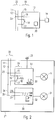
- Fig. 1 is a schematic representation of a connected to a communication bus 22 operating device 13 for lamp 14 according to an embodiment of the present invention shown.
- the operating device 13 is designed as a master in a master / slave control or regulation.
- the schematic representation of Fig. 1 corresponds to a part of an in Fig. 2 shown master / slave lighting system 21 or building services system.
- master operating devices or slave operating devices of building technology in particular for controlling bulbs such as OLEDs, LEDs or gas discharge lamps, for controlling actuators such as.
- master and slave had basically known control circuits for bulbs, as they are known, for example, for LEDs or OLEDs as an LED converter and for gas discharge lamps as electronic ballasts. Accordingly, master and slave also have DC or AC power supplies which are independent of the global and local ones explained below Bus installations and associated interfaces are present.
- the system 21 according to the invention is therefore preferably a master / slave system 21 of the building technology and in particular the lighting technology.
- This in Fig. 2 shown illumination system 21 is a locally communicating master / slave system, the master can be addressed by a global bus and can consist of two operating devices such as electronic ballasts for lighting, especially incandescent, gas discharge lamps or inorganic or organic light-emitting diodes.
- the two master and slave operating devices 13, 30 may be responsible for a direct and an indirect light component, for example, in one light.
- the system 21 may have more than two operating devices. In this case, preferably one master and several slaves are present.
- the communication bus 22 is preferably a two-wire bus having two lines in the form of a neutral conductor 11 and a phase conductor 12.
- the neutral conductor 11 and the phase conductor 12 are substantially parallel to each other according to a bus topology, also called line or line topology , This means that all bus users can be connected via taps directly to the bus 22.
- the master 13 and the slave 30 preferably each have an internal control unit 20, 32, which is designed to control the respectively connected lighting means 14, 31.
- the activation takes place according to, for example Commands such as dimming commands supplied to the master 13 and the slave 30.
- Such commands may be supplied to the master 13 and the slave 30 via the bus 22, for example, from a central control component (not shown).
- Master / slave system 21 may also internally issue dimming commands from master 13 to slave 30, these internal commands being independent of external dimming commands from a central control component.
- the master 13 is for this purpose preferably connected to a light sensor 33, and thus receives information about the light brightness of the environment of the system 21. It can thus also the brightness of the light source 14, 31 of the master 13 and the slave 30 generated light component can be determined.
- multiple light sensors may be connected to the master 13: different sensors detect e.g. the respective brightness of different light sources controlled by the master or a slave.
- the light component of the illuminant 14 controlled by the master 13 is regulated in such a way that the brightness actual values generated by the sensor 33 are received by the master and converted by its internal control unit 20 into nominal values for the illuminant 14.
- desired values for example, depending on the type of the luminous means, current, voltage, and / or desired power values can be envisaged.
- the light component of the light source 31 controlled by the slave 30 can now also be regulated starting from the sensor 33 connected to the master 13.
- the invention proposes a solution according to this aspect Transmission of new desired values or control values from the master 13 with sensor (eg light sensor, presence sensor, etc.) 33 to the slave 30, which is preferably not directly connected to a sensor or has no sensor.
- the invention uses a special interface 19 of the master.
- the master 13 according to the present invention has a total of three outputs 15, 16, 17 for connection to the bus 22.
- a first output 15 is directly connectable to the neutral conductor 11 from the communication bus 22, wherein the neutral conductor 11 extends completely outside the master 13. As in Fig. 1 or Fig. 2 shown, the output 15 is connected via a corresponding tap 23 to the neutral conductor 11.
- phase conductor 12 is not tapped. It is guided on the one hand to a second output 16 of the master 13, and on the other hand to a third output 17.
- the phase conductor 12 is connected in series with the second and the third output 17 and the phase conductor 12 is through the second and the third output 16, 17 looped through.
- the second and the third output 16, 17 are connected via a switch or opener 18.
- the switch 18 is preferably driven by the control unit 20, i. either open or closed.
- the first, second and third outputs 15, 16, 17, together with the switch 18, form the interface 19 of the master 13.
- a first input 36 and a second input 37 of the slave 30 are via two corresponding taps 34, 35 connected to the phase conductor 12 and the neutral conductor 11, see Fig. 2 ,
- the topology of the system 21 changes.
- a closed switch 18 the phase conductor 12 is not interrupted or not switched off, and the first input 36 of the slave is connected to the bus voltage.
- the slave 30 does not detect any bus voltage.
- the first input 36 of the slave is connected in this case to the third output 17 of the master, this third output 17 then having a voltage other than the bus voltage and preferably a zero voltage.
- the additional switch 18 is used according to the invention to transmit digital messages to the sequenced subscriber or to the slave 30.
- the digital signals can preferably be done by modulating the bus voltage. In the open state of the switch 18 is therefore at the input 36, 37 of the slave 30 no bus voltage.
- the slave detects in this case a so-called "low”. If the switch 18 of the master is closed, the bus voltage is present at the input 36, 37 of the slave 30. The slave detects in this case a so-called "high”. In this way, the master 13 can transmit digital commands to the slave 30 by appropriately opening and closing the switch 18.
- the digital signals supplied to the slave are generated not by modulating the voltage provided by the bus 22, but by modulating an alternative voltage.
- an alternative Voltage an internal low-voltage supply of the master 13 can be used.
- Another aspect of the invention is that these commands can only be received by the slave 30 and not by other bus subscribers.
- the opening and closing of the switch 18 for the remainder of the bus 22 are manifested only as small load changes, which usually only cause very minimal fluctuations in the high voltage V1 of the bus.
- the master may e.g. on the one hand to a digital bus, such as a DALI bus 22 to be connected, that uses the DALI (Digital Addressable Lighting Interface) protocol.
- the master can control the slave 30 with the same protocol, but also with an analog or a different digital protocol, such as the DSI (Digital Serial Interface) protocol designed for dimming electronic ballasts.
- DSI Digital Serial Interface
- the master / slave operation is flexible insofar as, for example, the implementation of new commands between master and slave can be made at any time independently of the remainder of the bus 22.
- the switch 18 preferably remains closed so that both subscribers, master 13 and slave 30, operate like other bus subscribers. So that the slave 30 can also be used as a complete bus user, for example in a DALI system, it is necessary that the slave 30 can also support and interpret the bus protocol, eg the DALI protocol.
Description
Die vorliegende Erfindung bezieht sich allgemein auf das Gebiet der busfähigen Betriebsgeräte für Leuchtmittel und insbesondere auf ein Beleuchtungssystem mit Master/Slave-Betriebsgeräten für Leuchtmittel.The present invention relates generally to the field of bus-enabled lighting equipment, and more particularly to a lighting system with master / slave lighting equipment.
Stand der Technik kann den folgenden Druckschriften entnommen werden:
-
US 2009/0051506 A1 -
US 6 421 710 B1 -
US 2004/0160199 A1 -
WO 2009/040014 A1 -
EP 1 320 222 A1 -
WO 2007/013003 A1
-
US 2009/0051506 A1 -
US Pat. No. 6,421,710 B1 -
US 2004/0160199 A1 -
WO 2009/040014 A1 -
EP 1 320 222 A1 -
WO 2007/013003 A1
Im Bereich der Gebäude- bzw. Beleuchtungstechnik können Betriebsgeräte untereinander verbunden und verkabelt, um beispielsweise eine zentrale Steuerung oder Regelung der einzelnen Geräte durchzuführen. Ein typisches digitales Lichtsteuersystem wird nach einer Bus-Topologie aufgebaut. Alle Teilnehmer bzw. alle Betriebsgeräte sind direkt mit einem Bus verbunden.In the field of building or lighting technology control gear can be interconnected and wired to perform, for example, a central control or regulation of the individual devices. A typical digital lighting control system is constructed according to a bus topology. All participants or all operating devices are connected directly to a bus.
Alternativ dazu gibt es in der Beleuchtungstechnik auch Master/Slave oder Mutter/Tochter Systeme. Solche Systeme bezeichnen in der Regel ein lokales, auf eine einzelne Leuchte beschränktes Master/Slave System aus typischerweise zwei elektronischen Vorschaltgeräten. Die zwei Vorschaltgeräte sind meistens in einer Leuchte für einen direkten und einen indirekten Lichtanteil zuständig. Dabei besteht der Wunsch, beide Lichtanteile mittels Lichtsensor, der an einem der zwei Vorschaltgeräte angeschlossen ist, zu regeln. Die Schwierigkeit ist unterdessen die Übermittlung neuer Stellwerte vom Master, i.e. vom Vorschaltgerät mit Lichtsensor, an den Slave.Alternatively, there are master / slave or mother / daughter systems in lighting technology. Such systems typically refer to a local, single lamp master / slave system typically consisting of two electronic ballasts. The two ballasts are usually responsible in a luminaire for a direct and an indirect light component. There is a desire to regulate both light components by means of light sensor, which is connected to one of the two ballasts. The difficulty, meanwhile, is the transmission of new control values from the master, i. from the ballast with light sensor, to the slave.
Einerseits kommt es vor, dass ein Vorschaltgerät die Rolle eines Masters nicht übernehmen kann. Entsprechend dem für Beleuchtungsanlagen ausgelegten DALI (Digital Addressable Lighting Interface) Protokoll ist so etwas z.B. nicht erlaubt. Andererseits fehlt dem Master-Vorschaltgerät notwendige Information über den Slave, insbesondere seine Adresse, um ihm Daten übersenden zu können. Lösen lassen sich diese Probleme gemäß dem Stand der Technik z.B. mittels Einsatz einer zentralen Steuereinheit, welche die entsprechenden Daten oder Dimm-Befehle von dem Master abholt und an den Slave weiterleitet.On the one hand, it happens that a ballast can not take on the role of a master. According to the designed for lighting installations DALI (Digital Addressable Lighting Interface) protocol is something such as not allowed. On the other hand, the master ballast lacks necessary information about the slave, in particular its address, in order to be able to send data to it. These problems can be solved according to the prior art, for example by using a central control unit, which picks up the corresponding data or dimming commands from the master and forwards them to the slave.
Es ist deshalb Aufgabe der vorliegenden Erfindung, ein Master/Slave Beleuchtungssystem und -Verfahren vorzuschlagen, welche die oben genannten Nachteile beheben. Der vorliegenden Erfindung liegt insbesondere nunmehr die Aufgabe zugrunde, eine alternative bzw. bessere Master/Slave Konfiguration anzugeben, die eine Vereinfachung der Kommunikation ermöglicht.It is therefore an object of the present invention to propose a master / slave lighting system and method which overcomes the above disadvantages. The object of the present invention is, in particular, to provide an alternative or better master / slave configuration which makes it possible to simplify the communication.
Die Aufgabe der vorliegenden Erfindung wird durch den Gegenstand der unabhängigen Ansprüche gelöst. Vorteilhafte Weiterbildungen der Erfindung sind Gegenstand der Unteransprüche.The object of the present invention is solved by the subject matter of the independent claims. Advantageous developments of the invention are the subject of the dependent claims.
Ein erster Aspekt der Erfindung betrifft ein Master/Slave System (an Betriebsmitteln der Gebäudetechnik, insbesondere für Leuchtmittel, mit
- einem Master-Betriebsgerät aufweisend
- eine Steuereinheit,
- einen ersten Bus-Anschluss und einen zweiten Anschluss, und
- einen Schalter zum selektiven Weiterleiten einer DC-Spannung an den zweiten Anschluss, und
- einem Slave-Betriebsgerät aufweisend einen Slave-Anschluss zum Anschließen an den zweiten Anschluss des Masters),
- having a master operating device
- a control unit,
- a first bus port and a second port, and
- a switch for selectively forwarding a DC voltage to the second terminal, and
- a slave operating device having a slave connection for connection to the second connection of the master),
Die DC-Spannung kann eine intern erzeugte oder extern zugeführte Spannung des Master-Betriebsgerät sein, also bspw. eine DC-Spannung, die
- in dem Master-Betriebsgerät intern bspw. durch eine Niedervolt-Spannungsversorgung erzeugt ist, oder
- dem ersten Bus-Anschluss bspw. als Ruhepegel einer dort angeschlossenen Busleitung zugeführt ist.
- in the master operating device internally, for example, is generated by a low-voltage power supply, or
- The first bus connection, for example, is supplied as a quiet level of a bus line connected there.
Das Master/Slave System kann weiterhin aufweisen eine Zentraleinheit, die mittels des ersten Busanschlusses mit dem Master-Betriebsgerät verbunden ist,
wobei bei geschlossenem Schalter das Slave-Betriebsgerät über die eine mit dem ersten Busanschluss des Master-Betriebsgeräts verbundene Busleitung ansprechbar ist.The master / slave system may further comprise a central unit, which is connected by means of the first bus connection to the master operating device,
wherein, when the switch is closed, the slave operating device can be addressed via the one bus line connected to the first bus connection of the master operating device.
Das Slave-Betriebsgerät kann dazu ausgebildet sein, Daten an den zweiten Anschluss des Master-Betriebsgeräts zu senden.The slave operating device may be configured to send data to the second terminal of the master operating device.
Bei geschlossenem Schalter können von dem Slave-Betriebsgerät gesendete Daten an eine an dem ersten Anschluss des Master-Betriebsgeräts verbundene Busleitung übertragen werden.When the switch is closed, data sent by the slave operating device can be transmitted to a bus line connected to the first connection of the master operating device.
Das Protokoll für eine an dem ersten Anschluss des Master-Betriebsgeräts verbundene Busleitung kann gleich oder unterschiedlich zu dem Protokoll für die Kommunikation zwischen dem Master-Betriebsgerät und dem Slave-Betriebsgerät sein.The protocol for a bus connected to the first terminal of the master operating device may be the same as or different from the protocol for the communication between the master operating device and the slave operating device.
Das Slave-Betriebsgerät kann ein Betriebsgerät für mindestens ein Leuchtmittel sein, und das Master-Betriebsgerät kann dem Slave-Betriebsgerät bspw. Dimm-Befehle für die von dem Slave-Betriebsgerät betriebenen Leuchtmittel übermitteln.The slave operating device may be an operating device for at least one light source, and the master operating device may transmit to the slave operating device, for example, dimming commands for the light source operated by the slave operating device.
Das Master-Betriebsgerät kann einen Sensor, insbesondere einen Helligkeitssensor oder einen Anwesenheitssensor aufweisen bzw. mit einem derartigen Sensor verbunden sein, so dass das Master-Betriebsgerät Befehle bspw. abhängig von der vom Sensor erfassten Helligkeit oder Anwesenheit an das Slave-Betriebsgerät übermitteln kann.The master operating device can have a sensor, in particular a brightness sensor or a presence sensor, or can be connected to such a sensor so that the master operating device can transmit commands, for example, depending on the brightness or presence detected by the sensor to the slave operating device.
Die vom Master-Betriebsgerät zum Slave-Betriebsgerät übertragenen Daten sind vorzugsweise nicht auf einem an dem ersten Busanschluss des Master-Betriebsgeräts angeschlossenen Bus sichtbar sind. Bspw. werden Dimmbefehle vom Master-Betriebsgerät ausschließlich vom Slave empfangen.The data transmitted from the master operating device to the slave operating device are preferably not visible on a bus connected to the first bus connection of the master operating device. For example. Dimming commands are only received by the master operating device from the slave.
Das Slave-Betriebsgerät ist vorzugsweise nicht ausgehend von einem an dem Busanschluss des Master-Betriebsgeräts angeschlossenen Bus adressierbar und weist vorzugsweise keine Betriebsadresse auf.The slave operating device is preferably not addressable from a bus connected to the bus connection of the master operating device and preferably has no operating address.
Ein weiterer Aspekt der Erfindung betrifft ein Master-Betriebsgerät für Leuchtmittel, das für ein System nach einem der vorhergehenden Ansprüche ausgebildet ist.Another aspect of the invention relates to a master operating device for lighting means, which is designed for a system according to one of the preceding claims.
Ein noch weiterer Aspekt der Erfindung betrifft ein Verfahren zur Kommunikation zwischen einem Master-Betriebsgerät und einem Slave-Betriebsgerät, wobei die Betriebsgeräte vorzugsweise Betriebsgeräte für Leuchtmittel sind,
wobei das Master-Betriebsgerät dem Slave-Betriebsgerät Daten durch Ansteuerung eines mit DC-Spannung versorgten Schalters übermittelt, und wobei das Slave-Betriebsgerät unabhängig von der Datenübermittlung mit Spannung versorgt wird.Yet another aspect of the invention relates to a method for communication between a master operating device and a slave operating device, wherein the operating devices are preferably operating devices for lighting means,
wherein the master operating device transmits data to the slave operating device by driving a switch supplied with DC voltage, and wherein the slave operating device is supplied with voltage independently of the data transmission.
Ein noch weiterer Aspekt betrifft eine Steuerschaltung, insbesondere Integrierte Schaltung wie bspw. ASIC, Mikrokontroller oder Hybrid davon, für ein Betriebsgerät für Leuchtmittel,
wobei die Steuerschaltung dazu ausgebildet ist, in einem Master-Betriebsgerät ein Verfahren der genannten Art zu unterstützen.Yet another aspect relates to a control circuit, in particular integrated circuit such as ASIC, microcontroller or hybrid thereof, for a control device for lighting means,
wherein the control circuit is adapted to support a method of the type mentioned in a master operating device.
Die Erfindung betrifft auch ein Betriebsgerät für Leuchtmittel, aufweisend eine derartige Steuerschaltung.The invention also relates to a control device for lighting means, comprising such a control circuit.
Im Folgenden wird der Erfindungsgegenstand anhand von bevorzugten Ausführungsbeispielen, welche in den beiliegenden Zeichnungen dargestellt sind, näher erläutert.
- Fig. 1
- zeigt eine schematische Darstellung eines Masters-Betriebsgeräts eines erfindungsgemäßen Master/Slave Systems.
- Fig. 2
- zeigt die schematische Darstellung einer Master/Slave bzw. Mutter/Tochter Verdrahtung entsprechend der vorliegenden Erfindung.
- Fig. 1
- shows a schematic representation of a master operating device of a master / slave system according to the invention.
- Fig. 2
- shows the schematic representation of a master / slave or mother / daughter Wiring according to the present invention.
In
Unter "Master" bzw. "Slave" sind im vorliegenden Rahmen Master-Betriebsgeräte bzw. Slave-Betriebsgeräte der Gebäudetechnik, insbesondere zur Ansteuerung von Leuchtmitteln wie bspw. OLEDs, LEDs oder Gasentladungslampen, zur Ansteuerung von Aktoren wie bspw. Jalousie-Steuerungen oder zur Kommunikation mit Sensoren wie bspw. Farb-, Temperatur-, Rauch-, Brand-, Licht- oder Bewegungssensoren und jegliche Kombination davon zu verstehen.Under "master" or "slave" are in this case master operating devices or slave operating devices of building technology, in particular for controlling bulbs such as OLEDs, LEDs or gas discharge lamps, for controlling actuators such as. Venetian blind controls or Communication with sensors such as color, temperature, smoke, fire, light or motion sensors and any combination thereof to understand.
Wie aus
Das erfindungsgemäße System 21 ist also vorzugsweise ein Master/Slave System 21 der Gebäudetechnik und insbesondere der Beleuchtungstechnik. Das in
Die zwei Master und Slave Betriebsgeräte 13, 30 können beispielsweise in einer Leuchte jeweils für einen direkten und einen indirekten Lichtanteil zuständig sein. Alternativ kann auch das System 21 mehr als zwei Betriebsgeräte aufweisen. In diesem Fall sind vorzugsweise ein Master und mehrere Slaves vorhanden.The two master and
Der Kommunikationsbus 22 ist vorzugsweise ein Zwei-Draht Bus aufweisend zwei Leitungen in Form eines Nullleiters bzw. Neutralleiters 11 und eines Phasenleiters 12. Der Neutralleiter 11 und der Phasenleiter 12 verlaufen im Wesentlichen parallel zueinander gemäß einer Bus-Topologie, auch Linien- oder Strangtopologie genannt. Das heißt, dass alle Bus-Teilnehmer über Abgriffe direkt mit dem Bus 22 verbunden sein können.The
Der Master 13 und der Slave 30 weisen vorzugsweise jeweils eine interne Steuereinheit 20, 32 auf, die dazu ausgelegt ist, das jeweils angeschlossene Leuchtmittel 14, 31 anzusteuern. Die Ansteuerung erfolgt zum Beispiel gemäß Befehlen wie Dimm-Befehlen, die dem Master 13 und dem Slave 30 zugeführt werden. Solche Befehle können beispielsweise ausgehend von einer zentralen Steuerkomponente (nicht gezeigt) über den Bus 22 dem Master 13 und dem Slave 30 zugeführt werden.The
Das Master/Slave System 21 kann auch intern Dimm-Befehle vom Master 13 zum Slave 30 ausgeben, wobei diese internen Befehle unabhängig von externen Dimm-Befehlen ausgehend von einer zentralen Steuerkomponente sind. Der Master 13 ist hierzu vorzugsweise mit einem Lichtsensor 33 verbunden, und erhält somit Informationen über die Lichthelligkeit der Umgebung des Systems 21. Es kann somit auch die Helligkeit des vom Leuchtmittel 14, 31 des Masters 13 bzw. des Slaves 30 erzeugten Lichtanteils ermittelt werden. Alternativ können auch mehrere Lichtsensoren an dem Master 13 angeschlossen sein: verschiedene Sensoren erfassen z.B. die jeweilige Helligkeit von verschiedenen durch den Master oder einen Slave angesteuerten Leuchtmitteln.Master /
Der Lichtanteil des vom Master 13 gesteuerten Leuchtmittels 14 wird derart geregelt, dass die vom Sensor 33 generierten Helligkeits-Ist-Werte vom Master empfangen werden, und von seiner internen Steuereinheit 20 in Soll-Werte für das Leuchtmittel 14 umgewandelt werden. Als Soll-Werte sind beispielsweise je nach Art des Leuchtmittels Strom-, Spannung-, und/oder Leistungs-Soll-Werte vorstellbar.The light component of the illuminant 14 controlled by the
Erfindungsgemäß kann nun auch der Lichtanteil des vom Slave 30 gesteuerten Leuchtmittels 31 ausgehend von dem am Master 13 angeschlossenen Sensor 33 geregelt werden. Die Erfindung schlägt gemäss diesem Aspekt eine Lösung vor zur Übermittlung neuer Soll-Werte bzw. Stellwerte vom Master 13 mit Sensor (bspw. Lichtsensor, Anwesenheitssensor, etc.) 33 an den Slave 30, der vorzugsweise nicht direkt mit einem Sensor verbunden ist bzw. keinen Sensor aufweist.According to the invention, the light component of the
Die Erfindung benutzt dabei eine besondere Schnittstelle 19 des Masters. Der Master 13 gemäß der vorliegenden Erfindung weist insgesamt drei Ausgänge 15, 16, 17 zum Verbinden mit dem Bus 22. Ein erster Ausgang 15 ist direkt mit dem Neutralleiter 11 vom Kommunikationsbus 22 verbindbar, wobei der Neutralleiter 11 komplett außerhalb vom Master 13 verläuft. Wie in
Dagegen wird der Phasenleiter 12 nicht abgegriffen. Er wird einerseits zu einem zweiten Ausgang 16 des Masters 13 geführt, und andererseits zu einem dritten Ausgang 17. Der Phasenleiter 12 ist in Serie mit der zweiten und mit dem dritten Ausgang 17 verbunden bzw. der Phasenleiter 12 wird durch den zweiten und den dritten Ausgang 16, 17 durchgeschleift. Innerhalb des Masters 13 sind der zweite und der dritte Ausgang 16, 17 über einen Schalter oder Öffner 18 verbunden. Der Schalter 18 wird vorzugsweise von der Steuereinheit 20 angesteuert, d.h. entweder geöffnet oder geschlossen. Die erste, zweite und dritte Ausgänge 15, 16, 17 bilden zusammen mit dem Schalter 18 die Schnittstelle 19 des Masters 13.In contrast, the
Der Slave 30 ist hingegen nur über Abgriffe mit dem Bus 22 verbunden. Ein erster Eingang 36 und ein zweiter Eingang 37 des Slaves 30 sind über zwei entsprechende Abgriffe 34, 35 mit dem Phasenleiter 12 und dem Neutralleiter 11 verbunden, sehe
Je nach Zustand des Schalters 18 ändert sich die Topologie des Systems 21. Bei einem geschlossenen Schalter 18 wird der Phasenleiter 12 nicht unterbrochen bzw. nicht abgeschaltet, und der erste Eingang 36 des Slaves ist mit der Busspannung verbunden. Bei einem geöffneten Schalter 18 detektiert der Slave 30 hingegen keine Busspannung. Der erste Eingang 36 des Slaves ist in diesem Fall mit dem dritten Ausgang 17 des Masters verbunden, wobei dieser dritte Ausgang 17 dann eine andere Spannung als die Busspannung und vorzugsweise eine Nullspannung aufweist.Depending on the state of the
Der zusätzliche Schalter 18 wird erfindungsgemäß dazu benutzt, digitale Nachrichten an den nachgereihten Teilnehmer bzw. an den Slave 30 zu übermitteln. Die digitalen Signale können vorzugsweise durch Modulieren der Busspannung erfolgen. Im offenen Zustand des Schalters 18 liegt am Eingang 36, 37 des Slaves 30 daher keine Busspannung an. Der Slave detektiert in diesem Fall ein sogenanntes "Low". Wird der Schalter 18 des Masters geschlossen, liegt am Eingang 36, 37 des Slaves 30 die Busspannung an. Der Slave detektiert in diesem Fall ein sogenanntes "High". Auf diese Weise kann der Master 13 durch entsprechendes Öffnen und Schließen des Schalters 18 digitale Kommandos an den Slave 30 übermitteln.The
Gemäß einer alternativen Ausführungsform der Erfindung werden die dem Slave zugeführten digitalen Signale nicht etwa durch Modulieren der vom Bus 22 zur Verfügung gestellten Spannung erzeugt, sondern durch Modulieren einer alternativen Spannung. Z.B. kann als alternative Spannung eine interne Niedervoltversorgung des Masters 13 benutzt werden.According to an alternative embodiment of the invention, the digital signals supplied to the slave are generated not by modulating the voltage provided by the
Ein weiterer Aspekt der Erfindung ist, dass diese Kommandos ausschließlich von dem Slave 30 und nicht von anderen Bus-Teilnehmern empfangen werden kann. In der Tat äußern sich das Öffnen und Schließen des Schalters 18 für den restlichen Bus 22 nur als kleine Laständerungen, die in der Regel nur sehr minimalen Schwankungen der High-Spannung bzw. Hoch-Spannung V1 des Busses bewirken.Another aspect of the invention is that these commands can only be received by the
Da ausschließlich der Slave 30 bzw. die Tochter die neuen Stellwerte des Masters 13 bzw. der Mutter empfangen kann, kann das digitale Protokoll, mit dem der Master dem Slave neue Stellwerte übermittelt, unabhängig vom Protokoll des Busses 22 gewählt werden. In einer Ausführungsform der Erfindung kann der Master z.B. einerseits an einen digitalen Bus, wie bspw. einen DALI-Bus 22 angeschlossen sein, der also das DALI (Digital Addressable Lighting Interface) Protokoll verwendet. Andererseits kann der Master den Slave 30 mit dem gleichen Protokoll, aber auch mit einem analogen oder einem abweichenden digitalen Protokoll ansteuern, wie bspw. dem zum Dimmen vom elektronischen Vorschaltgeräten ausgelegten DSI (Digital Serial Interface) Protokoll.Since only the
Da von Seite des Busses 22 und des Slaves 30 zwei unterschiedliche digitale Protokolle eingesetzt werden können, ist der Master/Slave Betrieb insofern flexibel, da z.B. die Implementierung neuer Kommandos zwischen Master und Slave jederzeit und unabhängig vom Rest des Busses 22 gemacht werden kann.Since two different digital protocols can be used from the side of the
Wenn diese Master/Slave Ansteuerung nicht gebraucht wird, bleibt der Schalter 18 vorzugsweise geschlossen, so dass beide Teilnehmer, Master 13 und Slave 30, wie andere Bus-Teilnehmer funktionieren. Damit der Slave 30 auch als vollständiger Bus-Teilnehmer z.B. in einem DALI-System benutzt werden kann, ist es notwendig, dass der Slave 30 das Bus-Protokoll z.B. das DALI-Protokoll auch unterstützt und interpretieren kann.If this master / slave drive is not needed, the
- 1111
- Neutralleiter vom KommunikationsbusNeutral from the communication bus
- 1212
- Phasenleiter vom KommunikationsbusPhase conductor from the communication bus
- 1313
- Master-BetriebsgerätMaster Control unit
- 1414
- LeuchtmittelLamp
- 1515
- erster Ausgangfirst exit
- 1616
- zweiter Ausgangsecond exit
- 1717
- dritter Ausgangthird exit
- 1818
- Schalterswitch
- 1919
- Schnittstelleinterface
- 2020
- Zentraleinheitcentral processing unit
- 2121
- Master/Slave BeleuchtungssystemMaster / slave lighting system
- 2222
- Kommunikationsbuscommunication
- 2323
- Angriffattack
- 3030
- Slave-BetriebsgerätSlave mode device
- 3131
- LeuchtmittelLamp
- 3232
- Steuereinheitcontrol unit
- 3333
- Lichtsensorlight sensor
- 34, 3534, 35
- Abgriffetaps
- 36, 3736, 37
- Eingängeinputs
Claims (13)
- A master/slave system (21) on operating means of the building technology, in particular for light sources (14, 31), having a master operating device (13) and a slave operating device (30), wherein the master operating device (13) and the slave operating device (30) are designed to be able to connect to a communication bus (22), wherein:- the master operating device (13) has:- a control unit (20);- a first bus connection (16) and a second connection (17), wherein the second connection (17) is designed for connecting with a slave-connection (36) of the slave operating device (30); and- a switch (18), which is designed, to connect the first bus-connection (16) and the second connection (17) and to selectively forward a DC voltage to the second connection (17), wherein:- through the selective forwarding of the DC voltage a data transmission from the master operating device (13) is made to the slave operating device (30),- the DC voltage is a voltage, which is generated internally in the master operating device (13) or is supplied to the first bus-connection (16) by the communication bus (22), and the control unit (20) is designed to make the data transmission from the master operating device (13) to the slave operating device (30) by the actuation of the switch (18);- the slave operating device (30) has the slave-connection (36) for connecting to the second connection (17) of the master (13);- the slave operating device (30) has a voltage supply independent of the data transmission from the master operating device (13) to the slave operating device (30).
- A master/slave system (21) according to Claim 1, wherein the DC voltage is a voltage, which- is generated internally by a low-voltage power supply in the master operating device (13), or- is supplied to the first bus-connection (16) as a quiescent level of a line of the communication bus (22) connected there.
- A master/slave system (21) according to Claim 1 or 2, furthermore having a central unit, which is connected by means of the first bus-connection (16) with the master operating device (13),
wherein when the switch (18) is closed the slave operating device (30) can be addressed via the bus line (22) connected with the first bus-connection (16) of the master operating device (30). - A master/slave system (21) according to any one of the preceding claims,
in which the slave operating device (30) is designed to be able to send data to the second connection (17) of the master operating device (13). - A master/slave system (21) according to Claim 4,
in which when the switch (18) is closed data sent from the slave operating device (30) are transmitted to a bus line (22) connected to the first bus-connection (16) of the master operating device (13). - A master/slave system (21) according to any one of the preceding claims,
wherein a protocol for a bus line connected to the first bus-connection (16) of the master operating device (13) is the same as or different from a protocol for the data transmission between the master operating device (13) and the slave operating device (30). - A master/slave system (21) according to any one of the preceding claims, wherein the slave operating device (30) is an operating device for at least one light source (31), and the master operating device (13) transmits dimming commands for the light source (31) to the slave operating device (30).
- A master/slave system (21) according to any one of the preceding claims, wherein the master operating device (13) has a sensor, in particular, a brightness sensor or a presence sensor (33) or is connected with a sensor, so that the master operating device (13) can transmit commands depending on the sensor detection, in particular, depending on a detected brightness or presence, to the slave operating device (30).
- A master/slave system (21) according to any one of the preceding claims, wherein the data transmitted from the master operating device (13) to the slave operating device (30) is not visible on a communication bus (22) connected to the first bus-connection (16) of the master operating device (13).
- A master/slave system (21) according to any one of the preceding claims, wherein the slave operating device (30) cannot be addressed starting from a communication bus (22) connected to the bus-connection (16) of the master operating device (13).
- A method for communication between a master operating device (13) and a slave operating device (30), wherein the operating devices are preferably operating devices for light sources and wherein the master operating device (13) and the slave operating device (30) are designed to be able to connect to a communication bus (22), wherein:- a switch (18) of the master operating device (13) connects a first bus-connection (16) of the master operating device (13) and a second connection (17) of the master operating device (13) and selectively forwards the DC voltage to the second connection (17) of the master operating device (13);- through the selective forwarding of the DC voltage a data transmission is made from the master operating device (13) to the slave operating device (30), wherein the second connection (17) of the master operating device (13) is designed with a slave connection (36) of the slave operating device (30) and wherein the DC voltage is generated internally in the master operating device (13) or is supplied to the first bus-connection (16) of the master operating device (13) by the communication bus (22);- a control unit (20) of the master operating device (13) makes the data transmission from the master operating unit (13) to the slave operating device (30) through an actuation of the switch (18); and- the slave operating device (30) is supplied with voltage independently of the data transmission.
- A control circuit, in particular, an integrated circuit such as, for example, ASIC, microcontroller or hybrid thereof, for an operating device for light sources,
wherein the control circuit is designed to carry out a method according to Claim 11 in a master operating device. - An operating device for light sources, having a control circuit according to Claim 12.
Applications Claiming Priority (2)
| Application Number | Priority Date | Filing Date | Title |
|---|---|---|---|
| DE102010002755A DE102010002755A1 (en) | 2010-03-11 | 2010-03-11 | Lighting system with master / slave control gear for bulbs |
| PCT/EP2011/053609 WO2011110626A1 (en) | 2010-03-11 | 2011-03-10 | Illumination system comprising master/slave operating devices for luminous elements |
Publications (2)
| Publication Number | Publication Date |
|---|---|
| EP2545683A1 EP2545683A1 (en) | 2013-01-16 |
| EP2545683B1 true EP2545683B1 (en) | 2017-05-24 |
Family
ID=43983728
Family Applications (1)
| Application Number | Title | Priority Date | Filing Date |
|---|---|---|---|
| EP11710719.3A Active EP2545683B1 (en) | 2010-03-11 | 2011-03-10 | Illumination system comprising master/slave operating devices for luminous elements |
Country Status (3)
| Country | Link |
|---|---|
| EP (1) | EP2545683B1 (en) |
| DE (2) | DE102010002755A1 (en) |
| WO (1) | WO2011110626A1 (en) |
Families Citing this family (2)
| Publication number | Priority date | Publication date | Assignee | Title |
|---|---|---|---|---|
| EP2948960B1 (en) * | 2013-01-23 | 2021-03-03 | Henkel IP & Holding GmbH | Flexible conductive ink |
| EP3154317A1 (en) * | 2015-10-08 | 2017-04-12 | ESYLUX GmbH | Master slave light system |
Citations (2)
| Publication number | Priority date | Publication date | Assignee | Title |
|---|---|---|---|---|
| EP1320222A1 (en) * | 2001-12-13 | 2003-06-18 | AMI Semiconductor Belgium BVBA | Multiplex transmission system with in-circuit addressing |
| WO2007013003A1 (en) * | 2005-07-27 | 2007-02-01 | Philips Intellectual Property & Standards Gmbh | Lighting system and method for controlling a plurality of light sources |
Family Cites Families (5)
| Publication number | Priority date | Publication date | Assignee | Title |
|---|---|---|---|---|
| DE19726763C2 (en) * | 1997-06-24 | 1999-06-10 | Phoenix Contact Gmbh & Co | Coupling arrangement for a master-slave bus system |
| EP0898442B1 (en) * | 1997-08-19 | 2003-03-05 | CEAG Sicherheitstechnik GmbH | Process and circuit for initialising and monitoring at least one electrical load |
| US7202613B2 (en) * | 2001-05-30 | 2007-04-10 | Color Kinetics Incorporated | Controlled lighting methods and apparatus |
| US8274397B2 (en) * | 2007-08-24 | 2012-09-25 | Sonoma Circuits, Inc. | Programmable light display |
| DE102007044817A1 (en) * | 2007-09-20 | 2009-04-09 | Insta Elektro Gmbh | Method for configuring a lighting bus system |
-
2010
- 2010-03-11 DE DE102010002755A patent/DE102010002755A1/en not_active Withdrawn
-
2011
- 2011-03-10 DE DE112011100862T patent/DE112011100862A5/en not_active Withdrawn
- 2011-03-10 WO PCT/EP2011/053609 patent/WO2011110626A1/en active Application Filing
- 2011-03-10 EP EP11710719.3A patent/EP2545683B1/en active Active
Patent Citations (2)
| Publication number | Priority date | Publication date | Assignee | Title |
|---|---|---|---|---|
| EP1320222A1 (en) * | 2001-12-13 | 2003-06-18 | AMI Semiconductor Belgium BVBA | Multiplex transmission system with in-circuit addressing |
| WO2007013003A1 (en) * | 2005-07-27 | 2007-02-01 | Philips Intellectual Property & Standards Gmbh | Lighting system and method for controlling a plurality of light sources |
Also Published As
| Publication number | Publication date |
|---|---|
| DE112011100862A5 (en) | 2013-05-16 |
| WO2011110626A1 (en) | 2011-09-15 |
| EP2545683A1 (en) | 2013-01-16 |
| DE102010002755A1 (en) | 2011-09-15 |
Similar Documents
| Publication | Publication Date | Title |
|---|---|---|
| DE102007004397B4 (en) | Method and system for data transmission | |
| DE102007044820B4 (en) | Bus system and method for its operation | |
| EP2554021B1 (en) | System-voltage transmission branch of an interface of an operating device for light-emitting means | |
| EP1555859A1 (en) | Control of lighting devices over a modulated DC bus | |
| EP2545751B1 (en) | Bus-type building services engineering system with daisy-chain topology | |
| EP2269423B1 (en) | Method for controlling an operating device for illumination means | |
| DE19544027C2 (en) | Bus system, especially for electrical installation | |
| EP2545683B1 (en) | Illumination system comprising master/slave operating devices for luminous elements | |
| EP3251469B1 (en) | Method for operating devices in a lighting system | |
| EP3213606B1 (en) | Method and apparatus for controlling an operating device for lighting means | |
| EP2545750B1 (en) | Light operating device system having variable bus topology | |
| AT506276B1 (en) | CONTROL OF LIGHTING SYSTEMS VIA A BUS | |
| WO2008040390A1 (en) | Lighting system and method for operating a lighting system | |
| AT507128B1 (en) | PROCEDURE FOR CONTROLLING A LAMP-DEVICE OPERATING DEVICE | |
| AT12594U1 (en) | INTERFACE FOR A BULB OPERATING DEVICE | |
| AT16321U1 (en) | Method of using a lighting system | |
| EP3119166B1 (en) | System and operating device for an actuator | |
| EP2992741B1 (en) | Method for controlling an operating device for lighting means | |
| WO2018197226A1 (en) | Method for controlling a lighting system | |
| EP1843446B1 (en) | Connecting assembly for electrical distribution in a building |
Legal Events
| Date | Code | Title | Description |
|---|---|---|---|
| PUAI | Public reference made under article 153(3) epc to a published international application that has entered the european phase |
Free format text: ORIGINAL CODE: 0009012 |
|
| 17P | Request for examination filed |
Effective date: 20120906 |
|
| AK | Designated contracting states |
Kind code of ref document: A1 Designated state(s): AL AT BE BG CH CY CZ DE DK EE ES FI FR GB GR HR HU IE IS IT LI LT LU LV MC MK MT NL NO PL PT RO RS SE SI SK SM TR |
|
| DAX | Request for extension of the european patent (deleted) | ||
| 17Q | First examination report despatched |
Effective date: 20150424 |
|
| REG | Reference to a national code |
Ref country code: DE Ref legal event code: R079 Ref document number: 502011012309 Country of ref document: DE Free format text: PREVIOUS MAIN CLASS: H04L0012420000 Ipc: H04L0012400000 |
|
| RIC1 | Information provided on ipc code assigned before grant |
Ipc: H04L 12/42 20060101ALI20150617BHEP Ipc: H05B 37/02 20060101ALI20150617BHEP Ipc: H04L 12/40 20060101AFI20150617BHEP Ipc: H04L 12/403 20060101ALI20150617BHEP |
|
| GRAP | Despatch of communication of intention to grant a patent |
Free format text: ORIGINAL CODE: EPIDOSNIGR1 |
|
| STAA | Information on the status of an ep patent application or granted ep patent |
Free format text: STATUS: GRANT OF PATENT IS INTENDED |
|
| INTG | Intention to grant announced |
Effective date: 20170220 |
|
| RIN1 | Information on inventor provided before grant (corrected) |
Inventor name: JUEN, REINHOLD |
|
| GRAS | Grant fee paid |
Free format text: ORIGINAL CODE: EPIDOSNIGR3 |
|
| GRAA | (expected) grant |
Free format text: ORIGINAL CODE: 0009210 |
|
| STAA | Information on the status of an ep patent application or granted ep patent |
Free format text: STATUS: THE PATENT HAS BEEN GRANTED |
|
| AK | Designated contracting states |
Kind code of ref document: B1 Designated state(s): AL AT BE BG CH CY CZ DE DK EE ES FI FR GB GR HR HU IE IS IT LI LT LU LV MC MK MT NL NO PL PT RO RS SE SI SK SM TR |
|
| REG | Reference to a national code |
Ref country code: GB Ref legal event code: FG4D Free format text: NOT ENGLISH |
|
| REG | Reference to a national code |
Ref country code: CH Ref legal event code: EP |
|
| REG | Reference to a national code |
Ref country code: IE Ref legal event code: FG4D Free format text: LANGUAGE OF EP DOCUMENT: GERMAN |
|
| REG | Reference to a national code |
Ref country code: AT Ref legal event code: REF Ref document number: 896491 Country of ref document: AT Kind code of ref document: T Effective date: 20170615 |
|
| REG | Reference to a national code |
Ref country code: DE Ref legal event code: R096 Ref document number: 502011012309 Country of ref document: DE |
|
| REG | Reference to a national code |
Ref country code: NL Ref legal event code: MP Effective date: 20170524 |
|
| REG | Reference to a national code |
Ref country code: LT Ref legal event code: MG4D |
|
| PG25 | Lapsed in a contracting state [announced via postgrant information from national office to epo] |
Ref country code: HR Free format text: LAPSE BECAUSE OF FAILURE TO SUBMIT A TRANSLATION OF THE DESCRIPTION OR TO PAY THE FEE WITHIN THE PRESCRIBED TIME-LIMIT Effective date: 20170524 Ref country code: ES Free format text: LAPSE BECAUSE OF FAILURE TO SUBMIT A TRANSLATION OF THE DESCRIPTION OR TO PAY THE FEE WITHIN THE PRESCRIBED TIME-LIMIT Effective date: 20170524 Ref country code: GR Free format text: LAPSE BECAUSE OF FAILURE TO SUBMIT A TRANSLATION OF THE DESCRIPTION OR TO PAY THE FEE WITHIN THE PRESCRIBED TIME-LIMIT Effective date: 20170825 Ref country code: NO Free format text: LAPSE BECAUSE OF FAILURE TO SUBMIT A TRANSLATION OF THE DESCRIPTION OR TO PAY THE FEE WITHIN THE PRESCRIBED TIME-LIMIT Effective date: 20170824 Ref country code: FI Free format text: LAPSE BECAUSE OF FAILURE TO SUBMIT A TRANSLATION OF THE DESCRIPTION OR TO PAY THE FEE WITHIN THE PRESCRIBED TIME-LIMIT Effective date: 20170524 Ref country code: LT Free format text: LAPSE BECAUSE OF FAILURE TO SUBMIT A TRANSLATION OF THE DESCRIPTION OR TO PAY THE FEE WITHIN THE PRESCRIBED TIME-LIMIT Effective date: 20170524 |
|
| PG25 | Lapsed in a contracting state [announced via postgrant information from national office to epo] |
Ref country code: SE Free format text: LAPSE BECAUSE OF FAILURE TO SUBMIT A TRANSLATION OF THE DESCRIPTION OR TO PAY THE FEE WITHIN THE PRESCRIBED TIME-LIMIT Effective date: 20170524 Ref country code: RS Free format text: LAPSE BECAUSE OF FAILURE TO SUBMIT A TRANSLATION OF THE DESCRIPTION OR TO PAY THE FEE WITHIN THE PRESCRIBED TIME-LIMIT Effective date: 20170524 Ref country code: IS Free format text: LAPSE BECAUSE OF FAILURE TO SUBMIT A TRANSLATION OF THE DESCRIPTION OR TO PAY THE FEE WITHIN THE PRESCRIBED TIME-LIMIT Effective date: 20170924 Ref country code: NL Free format text: LAPSE BECAUSE OF FAILURE TO SUBMIT A TRANSLATION OF THE DESCRIPTION OR TO PAY THE FEE WITHIN THE PRESCRIBED TIME-LIMIT Effective date: 20170524 Ref country code: LV Free format text: LAPSE BECAUSE OF FAILURE TO SUBMIT A TRANSLATION OF THE DESCRIPTION OR TO PAY THE FEE WITHIN THE PRESCRIBED TIME-LIMIT Effective date: 20170524 Ref country code: BG Free format text: LAPSE BECAUSE OF FAILURE TO SUBMIT A TRANSLATION OF THE DESCRIPTION OR TO PAY THE FEE WITHIN THE PRESCRIBED TIME-LIMIT Effective date: 20170824 |
|
| PG25 | Lapsed in a contracting state [announced via postgrant information from national office to epo] |
Ref country code: CZ Free format text: LAPSE BECAUSE OF FAILURE TO SUBMIT A TRANSLATION OF THE DESCRIPTION OR TO PAY THE FEE WITHIN THE PRESCRIBED TIME-LIMIT Effective date: 20170524 Ref country code: EE Free format text: LAPSE BECAUSE OF FAILURE TO SUBMIT A TRANSLATION OF THE DESCRIPTION OR TO PAY THE FEE WITHIN THE PRESCRIBED TIME-LIMIT Effective date: 20170524 Ref country code: DK Free format text: LAPSE BECAUSE OF FAILURE TO SUBMIT A TRANSLATION OF THE DESCRIPTION OR TO PAY THE FEE WITHIN THE PRESCRIBED TIME-LIMIT Effective date: 20170524 Ref country code: RO Free format text: LAPSE BECAUSE OF FAILURE TO SUBMIT A TRANSLATION OF THE DESCRIPTION OR TO PAY THE FEE WITHIN THE PRESCRIBED TIME-LIMIT Effective date: 20170524 Ref country code: SK Free format text: LAPSE BECAUSE OF FAILURE TO SUBMIT A TRANSLATION OF THE DESCRIPTION OR TO PAY THE FEE WITHIN THE PRESCRIBED TIME-LIMIT Effective date: 20170524 |
|
| REG | Reference to a national code |
Ref country code: DE Ref legal event code: R097 Ref document number: 502011012309 Country of ref document: DE |
|
| PG25 | Lapsed in a contracting state [announced via postgrant information from national office to epo] |
Ref country code: SM Free format text: LAPSE BECAUSE OF FAILURE TO SUBMIT A TRANSLATION OF THE DESCRIPTION OR TO PAY THE FEE WITHIN THE PRESCRIBED TIME-LIMIT Effective date: 20170524 Ref country code: IT Free format text: LAPSE BECAUSE OF FAILURE TO SUBMIT A TRANSLATION OF THE DESCRIPTION OR TO PAY THE FEE WITHIN THE PRESCRIBED TIME-LIMIT Effective date: 20170524 Ref country code: PL Free format text: LAPSE BECAUSE OF FAILURE TO SUBMIT A TRANSLATION OF THE DESCRIPTION OR TO PAY THE FEE WITHIN THE PRESCRIBED TIME-LIMIT Effective date: 20170524 |
|
| REG | Reference to a national code |
Ref country code: FR Ref legal event code: PLFP Year of fee payment: 8 |
|
| PLBE | No opposition filed within time limit |
Free format text: ORIGINAL CODE: 0009261 |
|
| STAA | Information on the status of an ep patent application or granted ep patent |
Free format text: STATUS: NO OPPOSITION FILED WITHIN TIME LIMIT |
|
| 26N | No opposition filed |
Effective date: 20180227 |
|
| PG25 | Lapsed in a contracting state [announced via postgrant information from national office to epo] |
Ref country code: SI Free format text: LAPSE BECAUSE OF FAILURE TO SUBMIT A TRANSLATION OF THE DESCRIPTION OR TO PAY THE FEE WITHIN THE PRESCRIBED TIME-LIMIT Effective date: 20170524 |
|
| PG25 | Lapsed in a contracting state [announced via postgrant information from national office to epo] |
Ref country code: MT Free format text: LAPSE BECAUSE OF FAILURE TO SUBMIT A TRANSLATION OF THE DESCRIPTION OR TO PAY THE FEE WITHIN THE PRESCRIBED TIME-LIMIT Effective date: 20170524 |
|
| REG | Reference to a national code |
Ref country code: CH Ref legal event code: PL |
|
| PG25 | Lapsed in a contracting state [announced via postgrant information from national office to epo] |
Ref country code: MC Free format text: LAPSE BECAUSE OF FAILURE TO SUBMIT A TRANSLATION OF THE DESCRIPTION OR TO PAY THE FEE WITHIN THE PRESCRIBED TIME-LIMIT Effective date: 20170524 |
|
| REG | Reference to a national code |
Ref country code: BE Ref legal event code: MM Effective date: 20180331 |
|
| REG | Reference to a national code |
Ref country code: IE Ref legal event code: MM4A |
|
| PG25 | Lapsed in a contracting state [announced via postgrant information from national office to epo] |
Ref country code: LU Free format text: LAPSE BECAUSE OF NON-PAYMENT OF DUE FEES Effective date: 20180310 |
|
| REG | Reference to a national code |
Ref country code: DE Ref legal event code: R084 Ref document number: 502011012309 Country of ref document: DE |
|
| PG25 | Lapsed in a contracting state [announced via postgrant information from national office to epo] |
Ref country code: IE Free format text: LAPSE BECAUSE OF NON-PAYMENT OF DUE FEES Effective date: 20180310 |
|
| PG25 | Lapsed in a contracting state [announced via postgrant information from national office to epo] |
Ref country code: BE Free format text: LAPSE BECAUSE OF NON-PAYMENT OF DUE FEES Effective date: 20180331 Ref country code: LI Free format text: LAPSE BECAUSE OF NON-PAYMENT OF DUE FEES Effective date: 20180331 Ref country code: CH Free format text: LAPSE BECAUSE OF NON-PAYMENT OF DUE FEES Effective date: 20180331 |
|
| PGFP | Annual fee paid to national office [announced via postgrant information from national office to epo] |
Ref country code: FR Payment date: 20190328 Year of fee payment: 9 |
|
| REG | Reference to a national code |
Ref country code: AT Ref legal event code: MM01 Ref document number: 896491 Country of ref document: AT Kind code of ref document: T Effective date: 20180310 |
|
| PG25 | Lapsed in a contracting state [announced via postgrant information from national office to epo] |
Ref country code: AT Free format text: LAPSE BECAUSE OF NON-PAYMENT OF DUE FEES Effective date: 20180310 |
|
| PG25 | Lapsed in a contracting state [announced via postgrant information from national office to epo] |
Ref country code: TR Free format text: LAPSE BECAUSE OF FAILURE TO SUBMIT A TRANSLATION OF THE DESCRIPTION OR TO PAY THE FEE WITHIN THE PRESCRIBED TIME-LIMIT Effective date: 20170524 |
|
| PG25 | Lapsed in a contracting state [announced via postgrant information from national office to epo] |
Ref country code: PT Free format text: LAPSE BECAUSE OF FAILURE TO SUBMIT A TRANSLATION OF THE DESCRIPTION OR TO PAY THE FEE WITHIN THE PRESCRIBED TIME-LIMIT Effective date: 20170524 Ref country code: HU Free format text: LAPSE BECAUSE OF FAILURE TO SUBMIT A TRANSLATION OF THE DESCRIPTION OR TO PAY THE FEE WITHIN THE PRESCRIBED TIME-LIMIT; INVALID AB INITIO Effective date: 20110310 |
|
| PG25 | Lapsed in a contracting state [announced via postgrant information from national office to epo] |
Ref country code: CY Free format text: LAPSE BECAUSE OF FAILURE TO SUBMIT A TRANSLATION OF THE DESCRIPTION OR TO PAY THE FEE WITHIN THE PRESCRIBED TIME-LIMIT Effective date: 20170524 Ref country code: MK Free format text: LAPSE BECAUSE OF NON-PAYMENT OF DUE FEES Effective date: 20170524 |
|
| PG25 | Lapsed in a contracting state [announced via postgrant information from national office to epo] |
Ref country code: AL Free format text: LAPSE BECAUSE OF FAILURE TO SUBMIT A TRANSLATION OF THE DESCRIPTION OR TO PAY THE FEE WITHIN THE PRESCRIBED TIME-LIMIT Effective date: 20170524 |
|
| PG25 | Lapsed in a contracting state [announced via postgrant information from national office to epo] |
Ref country code: FR Free format text: LAPSE BECAUSE OF NON-PAYMENT OF DUE FEES Effective date: 20200331 |
|
| PGFP | Annual fee paid to national office [announced via postgrant information from national office to epo] |
Ref country code: GB Payment date: 20220322 Year of fee payment: 12 |
|
| PGFP | Annual fee paid to national office [announced via postgrant information from national office to epo] |
Ref country code: DE Payment date: 20230328 Year of fee payment: 13 |
|
| P01 | Opt-out of the competence of the unified patent court (upc) registered |
Effective date: 20230530 |
|
| GBPC | Gb: european patent ceased through non-payment of renewal fee |
Effective date: 20230310 |
|
| PG25 | Lapsed in a contracting state [announced via postgrant information from national office to epo] |
Ref country code: GB Free format text: LAPSE BECAUSE OF NON-PAYMENT OF DUE FEES Effective date: 20230310 |
|
| PG25 | Lapsed in a contracting state [announced via postgrant information from national office to epo] |
Ref country code: GB Free format text: LAPSE BECAUSE OF NON-PAYMENT OF DUE FEES Effective date: 20230310 |