EP2543925A2 - Vehicle lamp - Google Patents
Vehicle lamp Download PDFInfo
- Publication number
- EP2543925A2 EP2543925A2 EP12175059A EP12175059A EP2543925A2 EP 2543925 A2 EP2543925 A2 EP 2543925A2 EP 12175059 A EP12175059 A EP 12175059A EP 12175059 A EP12175059 A EP 12175059A EP 2543925 A2 EP2543925 A2 EP 2543925A2
- Authority
- EP
- European Patent Office
- Prior art keywords
- light
- guide plate
- light guide
- lamp
- front side
- Prior art date
- Legal status (The legal status is an assumption and is not a legal conclusion. Google has not performed a legal analysis and makes no representation as to the accuracy of the status listed.)
- Withdrawn
Links
- 230000000694 effects Effects 0.000 description 9
- 230000007423 decrease Effects 0.000 description 8
- 230000004048 modification Effects 0.000 description 4
- 238000012986 modification Methods 0.000 description 4
- 230000003287 optical effect Effects 0.000 description 3
- 239000000758 substrate Substances 0.000 description 3
- 238000013459 approach Methods 0.000 description 2
- 238000004381 surface treatment Methods 0.000 description 2
- 230000002093 peripheral effect Effects 0.000 description 1
Images



Classifications
-
- G—PHYSICS
- G02—OPTICS
- G02B—OPTICAL ELEMENTS, SYSTEMS OR APPARATUS
- G02B6/00—Light guides; Structural details of arrangements comprising light guides and other optical elements, e.g. couplings
- G02B6/0001—Light guides; Structural details of arrangements comprising light guides and other optical elements, e.g. couplings specially adapted for lighting devices or systems
- G02B6/0011—Light guides; Structural details of arrangements comprising light guides and other optical elements, e.g. couplings specially adapted for lighting devices or systems the light guides being planar or of plate-like form
- G02B6/0066—Light guides; Structural details of arrangements comprising light guides and other optical elements, e.g. couplings specially adapted for lighting devices or systems the light guides being planar or of plate-like form characterised by the light source being coupled to the light guide
- G02B6/0073—Light emitting diode [LED]
-
- F—MECHANICAL ENGINEERING; LIGHTING; HEATING; WEAPONS; BLASTING
- F21—LIGHTING
- F21S—NON-PORTABLE LIGHTING DEVICES; SYSTEMS THEREOF; VEHICLE LIGHTING DEVICES SPECIALLY ADAPTED FOR VEHICLE EXTERIORS
- F21S41/00—Illuminating devices specially adapted for vehicle exteriors, e.g. headlamps
- F21S41/20—Illuminating devices specially adapted for vehicle exteriors, e.g. headlamps characterised by refractors, transparent cover plates, light guides or filters
- F21S41/24—Light guides
-
- F—MECHANICAL ENGINEERING; LIGHTING; HEATING; WEAPONS; BLASTING
- F21—LIGHTING
- F21S—NON-PORTABLE LIGHTING DEVICES; SYSTEMS THEREOF; VEHICLE LIGHTING DEVICES SPECIALLY ADAPTED FOR VEHICLE EXTERIORS
- F21S43/00—Signalling devices specially adapted for vehicle exteriors, e.g. brake lamps, direction indicator lights or reversing lights
- F21S43/20—Signalling devices specially adapted for vehicle exteriors, e.g. brake lamps, direction indicator lights or reversing lights characterised by refractors, transparent cover plates, light guides or filters
- F21S43/235—Light guides
- F21S43/236—Light guides characterised by the shape of the light guide
- F21S43/239—Light guides characterised by the shape of the light guide plate-shaped
-
- F—MECHANICAL ENGINEERING; LIGHTING; HEATING; WEAPONS; BLASTING
- F21—LIGHTING
- F21S—NON-PORTABLE LIGHTING DEVICES; SYSTEMS THEREOF; VEHICLE LIGHTING DEVICES SPECIALLY ADAPTED FOR VEHICLE EXTERIORS
- F21S43/00—Signalling devices specially adapted for vehicle exteriors, e.g. brake lamps, direction indicator lights or reversing lights
- F21S43/20—Signalling devices specially adapted for vehicle exteriors, e.g. brake lamps, direction indicator lights or reversing lights characterised by refractors, transparent cover plates, light guides or filters
- F21S43/235—Light guides
- F21S43/242—Light guides characterised by the emission area
- F21S43/245—Light guides characterised by the emission area emitting light from one or more of its major surfaces
-
- F—MECHANICAL ENGINEERING; LIGHTING; HEATING; WEAPONS; BLASTING
- F21—LIGHTING
- F21S—NON-PORTABLE LIGHTING DEVICES; SYSTEMS THEREOF; VEHICLE LIGHTING DEVICES SPECIALLY ADAPTED FOR VEHICLE EXTERIORS
- F21S43/00—Signalling devices specially adapted for vehicle exteriors, e.g. brake lamps, direction indicator lights or reversing lights
- F21S43/20—Signalling devices specially adapted for vehicle exteriors, e.g. brake lamps, direction indicator lights or reversing lights characterised by refractors, transparent cover plates, light guides or filters
- F21S43/235—Light guides
- F21S43/249—Light guides with two or more light sources being coupled into the light guide
-
- G—PHYSICS
- G02—OPTICS
- G02B—OPTICAL ELEMENTS, SYSTEMS OR APPARATUS
- G02B6/00—Light guides; Structural details of arrangements comprising light guides and other optical elements, e.g. couplings
- G02B6/0001—Light guides; Structural details of arrangements comprising light guides and other optical elements, e.g. couplings specially adapted for lighting devices or systems
- G02B6/0011—Light guides; Structural details of arrangements comprising light guides and other optical elements, e.g. couplings specially adapted for lighting devices or systems the light guides being planar or of plate-like form
- G02B6/0033—Means for improving the coupling-out of light from the light guide
- G02B6/0035—Means for improving the coupling-out of light from the light guide provided on the surface of the light guide or in the bulk of it
- G02B6/0045—Means for improving the coupling-out of light from the light guide provided on the surface of the light guide or in the bulk of it by shaping at least a portion of the light guide
- G02B6/0046—Tapered light guide, e.g. wedge-shaped light guide
-
- G—PHYSICS
- G02—OPTICS
- G02B—OPTICAL ELEMENTS, SYSTEMS OR APPARATUS
- G02B6/00—Light guides; Structural details of arrangements comprising light guides and other optical elements, e.g. couplings
- G02B6/0001—Light guides; Structural details of arrangements comprising light guides and other optical elements, e.g. couplings specially adapted for lighting devices or systems
- G02B6/0011—Light guides; Structural details of arrangements comprising light guides and other optical elements, e.g. couplings specially adapted for lighting devices or systems the light guides being planar or of plate-like form
- G02B6/0066—Light guides; Structural details of arrangements comprising light guides and other optical elements, e.g. couplings specially adapted for lighting devices or systems the light guides being planar or of plate-like form characterised by the light source being coupled to the light guide
- G02B6/0068—Arrangements of plural sources, e.g. multi-colour light sources
-
- G—PHYSICS
- G02—OPTICS
- G02B—OPTICAL ELEMENTS, SYSTEMS OR APPARATUS
- G02B6/00—Light guides; Structural details of arrangements comprising light guides and other optical elements, e.g. couplings
- G02B6/0001—Light guides; Structural details of arrangements comprising light guides and other optical elements, e.g. couplings specially adapted for lighting devices or systems
- G02B6/0011—Light guides; Structural details of arrangements comprising light guides and other optical elements, e.g. couplings specially adapted for lighting devices or systems the light guides being planar or of plate-like form
- G02B6/0013—Means for improving the coupling-in of light from the light source into the light guide
- G02B6/0015—Means for improving the coupling-in of light from the light source into the light guide provided on the surface of the light guide or in the bulk of it
- G02B6/002—Means for improving the coupling-in of light from the light source into the light guide provided on the surface of the light guide or in the bulk of it by shaping at least a portion of the light guide, e.g. with collimating, focussing or diverging surfaces
Definitions
- the present disclosure relates to a vehicle lamp including, a light guide plate.
- Some vehicle lamps are adapted to emit light to the front side of the lamp from its front surface by internally reflecting light, which is emitted from a plurality of light sources such as light-emitting diodes, by a plurality of reflective elements formed on its rear surface after making the light enter a light guide plate from a rear end face thereof.
- Japanese Patent Document JP-A-2005-122946 discloses a structure in which a side end face of the light guide plate, where the light emitted from the respective light sources enters, is disposed close to a rear end face in a direction facing the rear end face in such a vehicle lamp.
- the structure of the light guide plate it is possible to place the light guide plate so that it is curved along the shape of the vehicle body after easily securing a space in which the respective light sources are disposed.
- One or more exemplary embodiments of the present invention provide a vehicle lamp that can make a light guide plate appear to emit light uniformly in the front view of the lamp even when the light guide of the vehicle lamp has a structure that causes light emitted from respective light sources to enter the light guide plate from a rear end face.
- the foregoing feature is achieved based on a study on the shape of a light guide plate.
- a vehicle lamp includes a plurality of light sources, and a light guide plate configured to emit light to the front side of the lamp from a second surface facing a first surface by internally reflecting light, which is emitted from the respective light sources, by a plurality of reflective elements formed on the first surface after making the light enter the light guide plate from a rear end face of the light guide plate.
- the light guide plate is curved to the first surface and gradually becomes thinner toward the front side.
- the reflective elements are disposed at a predetermined interval in a longitudinal direction and extend in a direction crossing the longitudinal direction.
- the type of the "light source” is not restricted and may be, for example, a light-emitting diode.
- curved to the first surface toward the front side means that the light guide plate is curved so that a first surface side becomes concave and a second surface side becomes convex in a longitudinal direction.
- the "first surface side" may correspond to any one of an upward direction, a downward direction, a left direction, a right direction, and an inclined direction between the foregoing directions.
- the "internal reflection” performed by the respective “reflective elements” may be performed, for example, by total reflection and may be performed as normal mirror reflection by performing mirror surface treatment on the surfaces of the reflective elements.
- Light which enters the light guide plate from the rear end face of the light guide plate, is guided to the front side while total reflection of the light is repeated sequentially by the first and second surfaces, but the light guide plate is curved forward to the first surface. Accordingly, at a position ahead of the rear end face of the light guide plate so some extent, a portion of the light, which is reflected internally by the reflective elements of the first surface, reaches the second surface at an incidence angle smaller than a critical angle and is emitted from the second surface to the front side of the lamp.
- a portion of the light which continues to be guided further, is reflected internally at a position further ahead of the position by the reflective elements of the first surface, reaches the second surface at an incidence angle smaller than a critical angle, and is emitted from the second surface to the front side of the lamp.
- the thickness of the light guide plate which is curved to the first surface toward the front side, is constant, it is necessary to make larger a level difference between the front or rear end edges of the reflective elements, which are positioned on the further front side, of the respective reflective elements in order to make the light, which is reflected internally by the reflective elements of the first surface, reach the second surface at an incidence angle smaller than a critical angle.
- the light, which is guided to the front end portion of the light guide plate decreases in this case.
- the light guide plate gradually becomes thinner toward the front side, it is possible to prevent a level difference between the respective reflective elements from becoming excessively large and to guide light to the front end portion of the light guide plate easily. Accordingly, it is possible to make the light guide plate appear to emit light uniformly in the front view of the lamp.
- the guide plate of the vehicle lamp including the light guide plate is adapted to cause light, which is emitted from the respective light sources, to enter the light guide plate from the rear end face, it is possible to make the light guide plate appear to emit light uniformly in the front view of the lamp.
- the longitudinal width of the reflective element which is positioned on the further front side of the respective reflective elements, is set to the larger value, it is possible to obtain the following functional effect.
- Light guided in the light guide plate gradually decreases toward the front side. Accordingly, by setting the longitudinal width of the reflective element, which is positioned on the further front side, to a larger value, it is possible to make the intensity of light, which is internally reflected by the respective reflective elements and emitted from the second surface to the front side of the lamp, more uniform between the respective reflective elements. Therefore, it is possible to make the light guide plate appear to emit light uniformly in the front view of the lamp.
- a direction in which the light guide plate is curved in the longitudinal direction is opposite to a direction in which the light guide plate is curved in a direction orthogonal to the longitudinal direction. Accordingly, it is possible to make the design of the lamp have originality or to increase the degree of freedom in the layout of the lamp. For example, when the light guide plate is disposed so as to surround another lamp unit at the rear end area of the light guide plate, it is possible to obtain a design where the light guide plate is curved and widened forward toward the outer periphery from the periphery of the lamp unit.
- a “direction orthogonal to the longitudinal direction” in this case may be a width direction, a vertical direction, or an inclined direction.
- curved to the second surface toward an end portion in a direction orthogonal to the longitudinal direction ' means that the first surface is convex and the second surface side is curved to be convey in a direction orthogonal to the longitudinal direction.
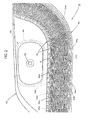
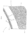
- Fig. 1 is a side cross-sectional view of a vehicle lamp 10. Further, Fig. 2 is a view seen in the direction of arrow II of Fig. 1 , and Fig. 3 is a view seen in the direction of arrow III of Fig. 1 .
- the vehicle lamp 10 is a daytime operating lamp that is provided at the left front end portion of a vehicle and is assembled in a lamp chamber, which is formed by a lamp body 12 and a transparent and translucent cover 14 mounted on the front end opening of the lamp body 12, together with a headlamp unit 50.
- the vehicle lamp 10 includes a plurality of light-emitting diodes 22 and a light guide plate 24.
- the light guide plate 24 is adapted to emit light to the front side of the lamp from its upper surface 24c by internally reflecting light, which is emitted from the respective light-emitting diodes 22, by a plurality of reflective elements 24s formed on a lower surface 24b thereof after causing the light to enter the light guide plate from a rear end face 24a thereof.
- a rear area 24A of the light guide plate 24 from the rear end face 24a to a predetermined front range is in the shape of a flat plate so as to extend along a horizontal plane, but a main area 24B formed on the front side of the rear area 24A is curved to the lower surface 24b and gradually becomes thinner toward the front side. Further, a front end area 24C of the light guide plate 24 is even more curved to the lower surface 24b toward the front side, and the thickness of the front end area 24C is slightly larger than that of the front end portion of the main area 24B.
- the light guide plate 24 is curved rearward toward its left end portion (the right end portion in Fig. 3 , similarly hereinafter) in a width direction of a vehicle.
- the rear end face 24a of the light guide plate 24 is displaced in the shape of a staircase at every position corresponding to the respective light-emitting diodes 22.
- the light guide plate 24 is curved to the upper surface 24c toward the left end portion thereof. Furthermore, the light guide plate 24 is fixed to the lamp body 12 at the lower end position and both left and right end positions of the front end area 24C.
- the light-emitting diodes 22 are disposed near the rear end face 24a of the light guide plate 24 so as to face the front side. Further, the light-emitting diodes 22 are disposed at substantially regular intervals in the width direction. In this case, the light-emitting diode 22, which is positioned on the further left side of the plurality of light-emitting diodes 22, is displaced further rearward in accordance with the rear end face 24a of the light guide plate 24 that is formed in the shape of a staircase.
- the light-emitting diodes 22 are fixed to upper end portions of the front surfaces of vertically long substrates 26, respectively. Further, the substrates 26 are fixed to the front surfaces of heat sinks 28 that extend in a vertical direction of the vehicle so as to have a substantially ⁇ -shaped cross-section, respectively. Furthermore, the respective heat sinks 28 are fixed to a common light source supporting member 30. Moreover, the light source supporting member 30 is fixed to the lamp body 12.
- a reflective panel 32 which is formed to extend substantially along the shape of the light guide plate 24, is disposed near the lower portion of the light guide plate 24. Since mirror surface treatment is performed on an upper surface 32a of the reflective panel 32, the reflective panel 32 is adapted to reflect the light that slightly leaks downward from the light guide plate 24.
- the rear area of the reflective panel 32 comes into close contact with the rear area 24A of the light guide plate 24, and the other area of the reflective panel is separated from the light guide plate 24.
- the reflective panel 32 is formed so that a gap between the light guide plate 24 and the reflective panel 32 gradually increases from the rear end position of the main area 24B of the light guide plate 24 toward the front end position of the main area. Further, the rear end face of the reflective panel 32 comes into contact with the substrates 26, and the lower surface of the front end portion of the reflective panel comes into contact with the lamp body 12.
- the headlamp unit 50 is positioned near the upper portion of the rear area 24A of the light guide plate 24.
- the headlamp unit 50 includes a light source bulb 52 and a reflector 54 that reflects the light emitted from the light source bulb 52 to the front side. Further, the headlamp unit 50 is supported on the lamp body 12 by an aiming mechanism (not shown).
- the light guide plate 24 detours around the headlamp unit 50 from the lower side of the headlamp unit to the left side of the headlamp unit.
- An extension member 60 which is formed in an annular shape so as to cover the front end opening of the reflector 54, is disposed near the front portion of the headlamp unit 50.
- the extension member 60 is disposed so that the lower area of the extension member 60 is positioned at a boundary portion between the rear area 24A and the main area 24B of the light guide plate 24, and the outer peripheral edge 60a of the lower end of the extension member 60 extends to a position that is slightly lower than the upper surface of the rear area 24A of the light guide plate 24.
- Fig. 4 is a view showing in greater detail the light guide plate 24, which is extracted from the vehicle lamp 10 shown in Fig. 1 , and optical paths of light, which is emitted from the light-etnitting diodes 22.
- Fig. 5 is a detailed view of a V portion of Fig. 4 .
- Fig. 4 shows an optical path of light that is emitted from the light emission center O of the light-emitting diode 22 and the light guide plate 24 from the rear end face 24a.
- the reflective elements 24s are formed on the main area 24B and the front end area 24C of the light guide plate 24.
- the reflective elements 24s extend in the width direction and are disposed at substantially regular intervals in a longitudinal direction of the vehicle.
- the longitudinal width of the reflective element 24s, which is positioned on the further front side, of the respective reflective elements 24s is set to a larger value.
- the respective reflective elements 24s the main area 24B are formed so that the pitch P of the reflective elements 24s in the longitudinal direction is substantially constant and the longitudinal width d of each of the reflective elements 24s gradually increases toward the front end position from the rear end position of the main area 24B.
- the probability that the light reaches the reflective element 24s decreases at the position near the rear end position of the main area 24B and the probability that the light reaches the reflective element 24s increases as the light approaches the front end position of the main area 248.
- the light is guided smoothly to the front end portion of the light guide plate 24.
- the reflective elements 24s are formed in the shape of a staircase at every position corresponding to the respective light-emitting diodes 22, as band-like areas 24Z extending in the longitudinal direction.
- the vehicle lamp 10 is adapted to emit light to the front side of the lamp from the upper surface 24c (that is, a second surface facing the lower surface 24b) by internally reflecting light, which is emitted from the respective light-emitting diodes 22 (i.e.,, light sources), by the reflective elements 24s on the lower surface 24b (i.e., a first surface) after causing the light to enter the light guide plate 24 from the rear end face 24a.
- the respective light-emitting diodes 22 i.e., light sources
- the reflective elements 24s on the lower surface 24b i.e., a first surface
- the light guide plate 24 is curved to the lower surface 24b and gradually becomes thinner toward the front side and the reflective elements 24s are disposed at a predetermined interval in the longitudinal direction and extend in the width direction (i.e.,, a direction crossing the longitudinal direction), it is possible to obtain the following functional effect.
- Light which enters the light guide plate 24 from the rear end face 24a of the light guide plate 24, is guided to the front side while the total reflection of the light is repeated sequentially by the lower surface 24b and the upper surface 24c, but the light guide plate 24 is curved forward to the lower surface 24b. Accordingly, at a position ahead of the rear end face 24a to some extent, a portion of the light, which is internally reflected by the reflective elements 24s of the lower surface 24b, reaches the upper surface 24c at an incidence angle smaller than a critical angle and is emitted from the upper surface 24c to the front side of the lamp.
- a portion of the light, which continues to be further guided, is reflected internally at a position further ahead of the position by the reflective elements 24s of the lower surface 24b, reaches the upper surface 24c at an incidence angle smaller than a critical angle, and is emitted from the upper surface 24c to the front side of the lamp.
- the thickness of the light guide plate 24, which is curved to the lower surface 24b toward the front side, is constant, it is necessary to make larger a level difference between the rear end edges of the reflective elements 24s, which are positioned on the further front side, of the respective reflective elements 24s to cause the light, which is internally reflected by the reflective elements 24s of the lower surface 24b, to reach the upper surface 24c at an incidence angle smaller than a critical angle.
- the light, which is guided to the front end portion of the light guide plate 24, decreases in this case.
- the light guide plate 24 of this embodiment gradually becomes thinner toward the front side, it is possible to prevent a level difference between the respective reflective elements 24s from becoming excessively large and to guide light easily to the front end portion of the light guide plate 24. Accordingly, it is possible to cause the light guide plate 24 to appear to emit light uniformly in the front view of the lamp.
- the guide plate 24 of the vehicle lamp 10 including the light guide plate 24 is adapted to cause light, which is emitted from the respective light-emitting diodes 22, to enter the light guide plate from the rear end face 24a, it is possible to cause the light guide plate 24 to appear to emit light uniformly in the front view of the lamp.
- the light guided in the light guide plate 24 gradually decreases toward the front side. Accordingly, by setting the longitudinal width d of the reflective element 24s, which is positioned on the further front side, to a larger value as in this embodiment, it is possible to make more uniform the intensity of light, which is internally reflected by the respective reflective elements 24s and emitted from the upper surface 24c to the front side of the lamp, between the respective reflective elements 24s. Therefore, it is possible to cause the light guide plate 24 to appear to emit light uniformly in the front view of the lamp.
- the pitch P of the reflective elements 24s, which are formed on the main area 24B, in the longitudinal direction is set to a substantially constant value in this embodiment, it is possible to obtain the following functional effect.
- the light guide plate 24 is curved to the upper surface 24c toward the left end portion in the width direction in this embodiment, a direction in which the light guide plate 24 is curved in the longitudinal direction is opposite to a direction in which the light guide plate 24 is curved in the width direction. Accordingly, it is possible to make the design of the lamp have originality or to increase the degree of freedom in the layout of the lamp. That is, in this embodiment, the light guide place 24 surrounds the headlamp unit 50 at the rear area 24A. However, in this case, it is possible to obtain a design where the light guide plate 24 is curved and widened forward toward the outer periphery from the periphery of the headlamp unit 50.
- the respective reflective elements 24s extend in the width direction.
- the respective reflective elements may extend in a direction such that the respective reflective elements are inclined in the longitudinal direction with respect to the width direction (for example, a direction parallel to the front end edge of the light guide plate 24).
- the vehicle lamp 10 is a daytime operating lamp provided at the left front end portion of a vehicle.
- the vehicle lamp 10 is a daytime operating lamp provided at the right front end portion of a vehicle
- a case where the vehicle lamp 10 is a lamp other than a daytime operating lamp and a case where the vehicle lamp 10 is a lamp provided at the rear end portion of a vehicle, it is possible to obtain the same functional effects as described above by employing the same structure as the structure of the foregoing example.
- Fig. 6 is a view, which is the same as Fig. 3 , showing a vehicle lamp 110 according to a modification of the foregoing example.
- the basic structure of the vehicle lamp 110 according to this modification is the same as that in the foregoing example, but the shape of a rear end face 124a of a light guide plate 124 of the vehicle lamp 110 is partially different from that in the case of the light guide plate 24 of the previous example.
- lens portions 124d which cause light emitted from the respective light-emitting diodes 22 to enter the light guide plate 124 in the form of light substantially parallel to a vertical plane, are formed at the positions, which correspond to the respective light-emitting diodes 22, on the rear end face 124a of the light guide plate 124 of this implementation.
Landscapes
- Physics & Mathematics (AREA)
- Engineering & Computer Science (AREA)
- General Engineering & Computer Science (AREA)
- General Physics & Mathematics (AREA)
- Optics & Photonics (AREA)
- Microelectronics & Electronic Packaging (AREA)
- Non-Portable Lighting Devices Or Systems Thereof (AREA)
- Planar Illumination Modules (AREA)
Abstract
Description
- The present disclosure relates to a vehicle lamp including, a light guide plate.
- Some vehicle lamps are adapted to emit light to the front side of the lamp from its front surface by internally reflecting light, which is emitted from a plurality of light sources such as light-emitting diodes, by a plurality of reflective elements formed on its rear surface after making the light enter a light guide plate from a rear end face thereof.
- Japanese Patent Document
JP-A-2005-122946 - If a structure that causes the light emitted from the respective light sources to enter the light guide plate from the rear end face is used as the structure of the light guide plate, it is possible to place the light guide plate so that it is curved along the shape of the vehicle body after easily securing a space in which the respective light sources are disposed.
- However, when the light emitted from the respective light sources enters the light guide plate from the rear end face as described above, it is necessary to cause the light to reach an emission surface of the light guide plate at an incidence angle smaller than a critical angle in order to emit the light, which enters the light guide plate, to the front side of the lamp. This, however, is not necessarily easy. For this reason, a problem can arise in that it also may not be easy to make the light guide plate appear to emit light uniformly in the front view of the lamp.
- One or more exemplary embodiments of the present invention provide a vehicle lamp that can make a light guide plate appear to emit light uniformly in the front view of the lamp even when the light guide of the vehicle lamp has a structure that causes light emitted from respective light sources to enter the light guide plate from a rear end face.
- In some implementations, the foregoing feature is achieved based on a study on the shape of a light guide plate.
- A vehicle lamp according to an exemplary embodiment includes a plurality of light sources, and a light guide plate configured to emit light to the front side of the lamp from a second surface facing a first surface by internally reflecting light, which is emitted from the respective light sources, by a plurality of reflective elements formed on the first surface after making the light enter the light guide plate from a rear end face of the light guide plate. The light guide plate is curved to the first surface and gradually becomes thinner toward the front side. The reflective elements are disposed at a predetermined interval in a longitudinal direction and extend in a direction crossing the longitudinal direction.
- The type of the "light source" is not restricted and may be, for example, a light-emitting diode.
- As long as the "light guide plate" is curved to the first surface and gradually becomes thinner toward the front side, the specific shape of the light guide plate is not restricted. In this case, "curved to the first surface toward the front side" means that the light guide plate is curved so that a first surface side becomes concave and a second surface side becomes convex in a longitudinal direction.
- The "first surface side" may correspond to any one of an upward direction, a downward direction, a left direction, a right direction, and an inclined direction between the foregoing directions.
- The "internal reflection" performed by the respective "reflective elements" may be performed, for example, by total reflection and may be performed as normal mirror reflection by performing mirror surface treatment on the surfaces of the reflective elements.
- In some implementations, it is possible to obtain the following functional effect.
- Light, which enters the light guide plate from the rear end face of the light guide plate, is guided to the front side while total reflection of the light is repeated sequentially by the first and second surfaces, but the light guide plate is curved forward to the first surface. Accordingly, at a position ahead of the rear end face of the light guide plate so some extent, a portion of the light, which is reflected internally by the reflective elements of the first surface, reaches the second surface at an incidence angle smaller than a critical angle and is emitted from the second surface to the front side of the lamp. Further, a portion of the light, which continues to be guided further, is reflected internally at a position further ahead of the position by the reflective elements of the first surface, reaches the second surface at an incidence angle smaller than a critical angle, and is emitted from the second surface to the front side of the lamp.
- In this case, since the light guide plate gradually becomes thinner toward the front side, it is possible to obtain the following functional effect.
- If the thickness of the light guide plate, which is curved to the first surface toward the front side, is constant, it is necessary to make larger a level difference between the front or rear end edges of the reflective elements, which are positioned on the further front side, of the respective reflective elements in order to make the light, which is reflected internally by the reflective elements of the first surface, reach the second surface at an incidence angle smaller than a critical angle. However, the light, which is guided to the front end portion of the light guide plate, decreases in this case. In that regard, if the light guide plate gradually becomes thinner toward the front side, it is possible to prevent a level difference between the respective reflective elements from becoming excessively large and to guide light to the front end portion of the light guide plate easily. Accordingly, it is possible to make the light guide plate appear to emit light uniformly in the front view of the lamp.
- In some implementations, even when the guide plate of the vehicle lamp including the light guide plate is adapted to cause light, which is emitted from the respective light sources, to enter the light guide plate from the rear end face, it is possible to make the light guide plate appear to emit light uniformly in the front view of the lamp.
- If the longitudinal width of the reflective element, which is positioned on the further front side of the respective reflective elements, is set to the larger value, it is possible to obtain the following functional effect.
- Light guided in the light guide plate gradually decreases toward the front side. Accordingly, by setting the longitudinal width of the reflective element, which is positioned on the further front side, to a larger value, it is possible to make the intensity of light, which is internally reflected by the respective reflective elements and emitted from the second surface to the front side of the lamp, more uniform between the respective reflective elements. Therefore, it is possible to make the light guide plate appear to emit light uniformly in the front view of the lamp.
- In this case, a level difference between the front or rear end edges of the reflective elements, which are positioned on the front side, is large. However, since the light guide plate gradually becomes thinner toward the front side, it is possible to prevent a level difference between the respective reflective elements from becoming excessively large.
- If the light guide plate is curved to the second surface toward an end portion in a direction orthogonal to the longitudinal direction in the above-mentioned structure, a direction in which the light guide plate is curved in the longitudinal direction is opposite to a direction in which the light guide plate is curved in a direction orthogonal to the longitudinal direction. Accordingly, it is possible to make the design of the lamp have originality or to increase the degree of freedom in the layout of the lamp. For example, when the light guide plate is disposed so as to surround another lamp unit at the rear end area of the light guide plate, it is possible to obtain a design where the light guide plate is curved and widened forward toward the outer periphery from the periphery of the lamp unit. A "direction orthogonal to the longitudinal direction" in this case may be a width direction, a vertical direction, or an inclined direction. Further, "curved to the second surface toward an end portion in a direction orthogonal to the longitudinal direction"' means that the first surface is convex and the second surface side is curved to be convey in a direction orthogonal to the longitudinal direction.
- Other aspects, features and advantages will be apparent from the following detailed description, the accompanying drawings, and the claim.
- The above and other aspects of the present invention will become more apparent from the following description of exemplary embodiments, taken in conjunction with the accompanying drawings of which:
-
Fig. 1 is a side cross-sectional view of a vehicle lamp according to an embodiment. -
Fig. 2 is a view seen in the direction of arrow II ofFig. 1 . -
Fig. 3 is a view seen in the direction of arrow III ofFig. 1 . -
Fig. 4 is a view showing a light guide plate, which is extracted from the vehicle lamp shown inFig. 1 , and optical paths of light, which are emitted from a light source, in detail. -
Fig. 5 is a detailed view of the V portion ofFig. 4 . -
Fig. 6 is a view, which is the same asFig. 3 , showing a vehicle lamp according to a modification of the embodiment. - An example of an embodiment of the invention is described below with reference to the drawings.
-
Fig. 1 is a side cross-sectional view of avehicle lamp 10. Further,Fig. 2 is a view seen in the direction of arrow II ofFig. 1 , andFig. 3 is a view seen in the direction of arrow III ofFig. 1 . - As shown in these drawings, the
vehicle lamp 10 is a daytime operating lamp that is provided at the left front end portion of a vehicle and is assembled in a lamp chamber, which is formed by alamp body 12 and a transparent andtranslucent cover 14 mounted on the front end opening of thelamp body 12, together with aheadlamp unit 50. - The
vehicle lamp 10 includes a plurality of light-emitting diodes 22 and alight guide plate 24. - As shown in
Fig. 1 , thelight guide plate 24 is adapted to emit light to the front side of the lamp from itsupper surface 24c by internally reflecting light, which is emitted from the respective light-emitting diodes 22, by a plurality ofreflective elements 24s formed on alower surface 24b thereof after causing the light to enter the light guide plate from arear end face 24a thereof. - A
rear area 24A of thelight guide plate 24 from therear end face 24a to a predetermined front range is in the shape of a flat plate so as to extend along a horizontal plane, but amain area 24B formed on the front side of therear area 24A is curved to thelower surface 24b and gradually becomes thinner toward the front side. Further, afront end area 24C of thelight guide plate 24 is even more curved to thelower surface 24b toward the front side, and the thickness of thefront end area 24C is slightly larger than that of the front end portion of themain area 24B. - As shown in
Fig. 3 , thelight guide plate 24 is curved rearward toward its left end portion (the right end portion inFig. 3 , similarly hereinafter) in a width direction of a vehicle. In accordance with this feature, therear end face 24a of thelight guide plate 24 is displaced in the shape of a staircase at every position corresponding to the respective light-emitting diodes 22. Further, as shown inFig. 2 , thelight guide plate 24 is curved to theupper surface 24c toward the left end portion thereof. Furthermore, thelight guide plate 24 is fixed to thelamp body 12 at the lower end position and both left and right end positions of thefront end area 24C. - The light-emitting
diodes 22 are disposed near therear end face 24a of thelight guide plate 24 so as to face the front side. Further, the light-emittingdiodes 22 are disposed at substantially regular intervals in the width direction. In this case, the light-emittingdiode 22, which is positioned on the further left side of the plurality of light-emittingdiodes 22, is displaced further rearward in accordance with therear end face 24a of thelight guide plate 24 that is formed in the shape of a staircase. - The light-emitting
diodes 22 are fixed to upper end portions of the front surfaces of verticallylong substrates 26, respectively. Further, thesubstrates 26 are fixed to the front surfaces ofheat sinks 28 that extend in a vertical direction of the vehicle so as to have a substantially π-shaped cross-section, respectively. Furthermore, therespective heat sinks 28 are fixed to a common lightsource supporting member 30. Moreover, the lightsource supporting member 30 is fixed to thelamp body 12. - A
reflective panel 32, which is formed to extend substantially along the shape of thelight guide plate 24, is disposed near the lower portion of thelight guide plate 24. Since mirror surface treatment is performed on anupper surface 32a of thereflective panel 32, thereflective panel 32 is adapted to reflect the light that slightly leaks downward from thelight guide plate 24. - The rear area of the
reflective panel 32 comes into close contact with therear area 24A of thelight guide plate 24, and the other area of the reflective panel is separated from thelight guide plate 24. In this case, thereflective panel 32 is formed so that a gap between thelight guide plate 24 and thereflective panel 32 gradually increases from the rear end position of themain area 24B of thelight guide plate 24 toward the front end position of the main area. Further, the rear end face of thereflective panel 32 comes into contact with thesubstrates 26, and the lower surface of the front end portion of the reflective panel comes into contact with thelamp body 12. - The
headlamp unit 50 is positioned near the upper portion of therear area 24A of thelight guide plate 24. - The
headlamp unit 50 includes alight source bulb 52 and areflector 54 that reflects the light emitted from thelight source bulb 52 to the front side. Further, theheadlamp unit 50 is supported on thelamp body 12 by an aiming mechanism (not shown). - The
light guide plate 24 detours around theheadlamp unit 50 from the lower side of the headlamp unit to the left side of the headlamp unit. - An
extension member 60, which is formed in an annular shape so as to cover the front end opening of thereflector 54, is disposed near the front portion of theheadlamp unit 50. - The
extension member 60 is disposed so that the lower area of theextension member 60 is positioned at a boundary portion between therear area 24A and themain area 24B of thelight guide plate 24, and the outerperipheral edge 60a of the lower end of theextension member 60 extends to a position that is slightly lower than the upper surface of therear area 24A of thelight guide plate 24. -
Fig. 4 is a view showing in greater detail thelight guide plate 24, which is extracted from thevehicle lamp 10 shown inFig. 1 , and optical paths of light, which is emitted from the light-etnitting diodes 22.Fig. 5 is a detailed view of a V portion ofFig. 4 . - In this case,
Fig. 4 shows an optical path of light that is emitted from the light emission center O of the light-emittingdiode 22 and thelight guide plate 24 from therear end face 24a. - As shown in
Fig. 4 , thereflective elements 24s are formed on themain area 24B and thefront end area 24C of thelight guide plate 24. - The
reflective elements 24s extend in the width direction and are disposed at substantially regular intervals in a longitudinal direction of the vehicle. In this case, the longitudinal width of thereflective element 24s, which is positioned on the further front side, of the respectivereflective elements 24s is set to a larger value. - That is, as shown in
Fig. 5 , the respectivereflective elements 24s themain area 24B are formed so that the pitch P of thereflective elements 24s in the longitudinal direction is substantially constant and the longitudinal width d of each of thereflective elements 24s gradually increases toward the front end position from the rear end position of themain area 24B. - Accordingly, as for light that enters the
light guide plate 24 from therear end face 24a of thelight guide plate 24 and is guided to the front side while the total reflection of the light is sequentially repeated by thelower surface 24b and theupper surface 24c, the probability that the light reaches thereflective element 24s decreases at the position near the rear end position of themain area 24B and the probability that the light reaches thereflective element 24s increases as the light approaches the front end position of the main area 248. As a result, the light is guided smoothly to the front end portion of thelight guide plate 24. - As shown in
Fig. 3 , thereflective elements 24s are formed in the shape of a staircase at every position corresponding to the respective light-emittingdiodes 22, as band-like areas 24Z extending in the longitudinal direction. - Functional effects of this embodiment are described below.
- The
vehicle lamp 10 according to this embodiment is adapted to emit light to the front side of the lamp from theupper surface 24c (that is, a second surface facing thelower surface 24b) by internally reflecting light, which is emitted from the respective light-emitting diodes 22 (i.e.,, light sources), by thereflective elements 24s on thelower surface 24b (i.e.,, a first surface) after causing the light to enter thelight guide plate 24 from therear end face 24a. However, since thelight guide plate 24 is curved to thelower surface 24b and gradually becomes thinner toward the front side and thereflective elements 24s are disposed at a predetermined interval in the longitudinal direction and extend in the width direction (i.e.,, a direction crossing the longitudinal direction), it is possible to obtain the following functional effect. - Light, which enters the
light guide plate 24 from therear end face 24a of thelight guide plate 24, is guided to the front side while the total reflection of the light is repeated sequentially by thelower surface 24b and theupper surface 24c, but thelight guide plate 24 is curved forward to thelower surface 24b. Accordingly, at a position ahead of therear end face 24a to some extent, a portion of the light, which is internally reflected by thereflective elements 24s of thelower surface 24b, reaches theupper surface 24c at an incidence angle smaller than a critical angle and is emitted from theupper surface 24c to the front side of the lamp. Further, a portion of the light, which continues to be further guided, is reflected internally at a position further ahead of the position by thereflective elements 24s of thelower surface 24b, reaches theupper surface 24c at an incidence angle smaller than a critical angle, and is emitted from theupper surface 24c to the front side of the lamp. - In this case, since the
light guide plate 24 gradually becomes thinner toward the front side, it is possible to obtain the following functional effect. - If the thickness of the
light guide plate 24, which is curved to thelower surface 24b toward the front side, is constant, it is necessary to make larger a level difference between the rear end edges of thereflective elements 24s, which are positioned on the further front side, of the respectivereflective elements 24s to cause the light, which is internally reflected by thereflective elements 24s of thelower surface 24b, to reach theupper surface 24c at an incidence angle smaller than a critical angle. However, the light, which is guided to the front end portion of thelight guide plate 24, decreases in this case. In that regard, since thelight guide plate 24 of this embodiment gradually becomes thinner toward the front side, it is possible to prevent a level difference between the respectivereflective elements 24s from becoming excessively large and to guide light easily to the front end portion of thelight guide plate 24. Accordingly, it is possible to cause thelight guide plate 24 to appear to emit light uniformly in the front view of the lamp. - According to this embodiment, even when the
guide plate 24 of thevehicle lamp 10 including thelight guide plate 24 is adapted to cause light, which is emitted from the respective light-emittingdiodes 22, to enter the light guide plate from therear end face 24a, it is possible to cause thelight guide plate 24 to appear to emit light uniformly in the front view of the lamp. - In this case, since the longitudinal width d of the
reflective element 24s, which is positioned on the further front side, of the respectivereflective elements 24s is set to a larger value in this embodiment, it is possible to obtain the following functional effect. - The light guided in the
light guide plate 24 gradually decreases toward the front side. Accordingly, by setting the longitudinal width d of thereflective element 24s, which is positioned on the further front side, to a larger value as in this embodiment, it is possible to make more uniform the intensity of light, which is internally reflected by the respectivereflective elements 24s and emitted from theupper surface 24c to the front side of the lamp, between the respectivereflective elements 24s. Therefore, it is possible to cause thelight guide plate 24 to appear to emit light uniformly in the front view of the lamp. - Meanwhile, in this case, a level difference between the rear end edges of the
reflective elements 24s, which are positioned on the front side, is large. However, since thelight guide plate 24 gradually becomes thinner toward the front side, it is possible to prevent a level difference between the respectivereflective elements 24s from becoming excessively large. - In addition, since the pitch P of the
reflective elements 24s, which are formed on themain area 24B, in the longitudinal direction is set to a substantially constant value in this embodiment, it is possible to obtain the following functional effect. - As for light that enters the
light guide plate 24 from therear end face 24a of thelight guide plate 24 and is guided to the front side while the total reflection of the light is repeated sequentially by thelower surface 24b and theupper surface 24c, the probability that the light reaches thereflective element 24s decreases since a value t (=P-d) is large at the position near the rear end position of themain area 24B and the probability that the light reaches thereflective element 24s increases since a value t gradually decreases as the light approaches the front end position of themain area 24B. Accordingly, it is possible to guide the light to the front end portion of thelight guide plate 24 more smoothly. - Further, since the
light guide plate 24 is curved to theupper surface 24c toward the left end portion in the width direction in this embodiment, a direction in which thelight guide plate 24 is curved in the longitudinal direction is opposite to a direction in which thelight guide plate 24 is curved in the width direction. Accordingly, it is possible to make the design of the lamp have originality or to increase the degree of freedom in the layout of the lamp. That is, in this embodiment, thelight guide place 24 surrounds theheadlamp unit 50 at therear area 24A. However, in this case, it is possible to obtain a design where thelight guide plate 24 is curved and widened forward toward the outer periphery from the periphery of theheadlamp unit 50. - In the foregoing example, the value t (=P-d) is set to decrease gradually toward the front end position after the pitch P of the respective
reflective elements 24s in the longitudinal direction is set to a substantially constant value, in order to make the longitudinal width d of each of thereflective elements 24s gradually increase toward the front end position from the rear end position of themain area 24B. However, instead of this, the pitch P of the respectivereflective elements 24s in the longitudinal direction may be set to gradually increase toward the front end position after the value t (=P-d) is set to a substantially constant value. - Moreover, in the foregoing example, the respective
reflective elements 24s extend in the width direction. However, the respective reflective elements may extend in a direction such that the respective reflective elements are inclined in the longitudinal direction with respect to the width direction (for example, a direction parallel to the front end edge of the light guide plate 24). - An example in which the
vehicle lamp 10 is a daytime operating lamp provided at the left front end portion of a vehicle has been described in the foregoing example. However, even in a case where thevehicle lamp 10 is a daytime operating lamp provided at the right front end portion of a vehicle, a case where thevehicle lamp 10 is a lamp other than a daytime operating lamp, and a case where thevehicle lamp 10 is a lamp provided at the rear end portion of a vehicle, it is possible to obtain the same functional effects as described above by employing the same structure as the structure of the foregoing example. - A modification of the above-mentioned embodiment is described next.
-
Fig. 6 is a view, which is the same asFig. 3 , showing avehicle lamp 110 according to a modification of the foregoing example. - As shown in
Fig. 6 , the basic structure of thevehicle lamp 110 according to this modification is the same as that in the foregoing example, but the shape of arear end face 124a of alight guide plate 124 of thevehicle lamp 110 is partially different from that in the case of thelight guide plate 24 of the previous example. - In particular,
lens portions 124d, which cause light emitted from the respective light-emittingdiodes 22 to enter thelight guide plate 124 in the form of light substantially parallel to a vertical plane, are formed at the positions, which correspond to the respective light-emittingdiodes 22, on therear end face 124a of thelight guide plate 124 of this implementation. - It is possible to make the light, which is emitted from the respective light-emitting
diodes 22, efficiently enter band-like areas 124Z, which are positioned in front of the respective light-emitting diodes, by employing the structure of this implementation. Accordingly, it is possible to make the respectivereflective elements 124s of thelight guide plate 124 appear to emit light more brightly in the front view of the lamp. - The numerical values, which are described in the foregoing examples as dimensions, are merely illustrative; the dimensions may be appropriately set to different values in other implementations.
Claims (3)
- A vehicle lamp (10, 110) comprising:a plurality of light sources (22); anda light guide plate (24, 124) arranged to emit light to the front side of the lamp (10) from a second surface (24c) facing a first surface (24b) by internally reflecting light, which is emitted from the respective light sources (22), by a plurality of reflective elements (24s, 124s) on the first surface (24b) after causing the light to enter the light guide plate (24, 124) from a rear end face (24a, 124a) of the light guide plate,wherein the light guide plate (24, 124) is curved to the first surface (24b) and gradually becomes thinner toward the front side, andthe plurality of reflective elements (24s, 124s) are disposed at a predetermined interval in a longitudinal direction and extend in a direction crossing the longitudinal direction.
- The vehicle lamp (10, 110) according to claim 1, wherein a longitudinal width (d) of the reflective element, which is positioned on the further front side, of the respective reflective elements (24s, 124s) is set to a larger value.
- The vehicle lamp (10,110) according to claim 1 or 2, wherein the light guide plate (24, 124) is curved to the second surface (24c) toward an end portion in a direction orthogonal to the longitudinal direction.
Applications Claiming Priority (1)
| Application Number | Priority Date | Filing Date | Title |
|---|---|---|---|
| JP2011149152A JP5753012B2 (en) | 2011-07-05 | 2011-07-05 | Vehicle lighting |
Publications (2)
| Publication Number | Publication Date |
|---|---|
| EP2543925A2 true EP2543925A2 (en) | 2013-01-09 |
| EP2543925A3 EP2543925A3 (en) | 2014-01-22 |
Family
ID=46466229
Family Applications (1)
| Application Number | Title | Priority Date | Filing Date |
|---|---|---|---|
| EP12175059.0A Withdrawn EP2543925A3 (en) | 2011-07-05 | 2012-07-05 | Vehicle lamp |
Country Status (4)
| Country | Link |
|---|---|
| US (1) | US8708538B2 (en) |
| EP (1) | EP2543925A3 (en) |
| JP (1) | JP5753012B2 (en) |
| CN (1) | CN102865540B (en) |
Cited By (3)
| Publication number | Priority date | Publication date | Assignee | Title |
|---|---|---|---|---|
| WO2016135461A3 (en) * | 2015-02-26 | 2016-10-27 | Bentley Motors Limited | Vehicle light assembly and lighting method |
| CN113597529A (en) * | 2019-04-11 | 2021-11-02 | 株式会社小糸制作所 | Vehicle lamp |
| WO2025040763A1 (en) * | 2023-08-22 | 2025-02-27 | Marelli Automotive Lighting Reutlingen (Germany) GmbH | Lighting arrangement with radar-transparent portion and curved light in-coupling surface |
Families Citing this family (20)
| Publication number | Priority date | Publication date | Assignee | Title |
|---|---|---|---|---|
| JP2013109942A (en) * | 2011-11-21 | 2013-06-06 | Koito Mfg Co Ltd | Vehicular lamp |
| JP5945238B2 (en) * | 2013-03-11 | 2016-07-05 | 株式会社豊田自動織機 | Vehicle lamp and vehicle rear panel |
| JP6227346B2 (en) * | 2013-09-25 | 2017-11-08 | スタンレー電気株式会社 | Light guide plate, surface light emitting device, and vehicle lamp |
| JP6514912B2 (en) * | 2015-02-26 | 2019-05-15 | 株式会社村上開明堂 | Turn lamp |
| DE102016119321A1 (en) * | 2016-10-11 | 2018-04-12 | HELLA GmbH & Co. KGaA | Lighting device for a motor vehicle, in particular headlight of a motor vehicle |
| US10816156B2 (en) | 2017-02-14 | 2020-10-27 | Everlight Electronics Co., Ltd. | Light guiding element, light guiding device, and lighting module |
| JP6814070B2 (en) * | 2017-02-22 | 2021-01-13 | スタンレー電気株式会社 | Vehicle lighting |
| TWI695521B (en) | 2017-08-04 | 2020-06-01 | 億光電子工業股份有限公司 | Led package structure and manufacturing method thereof |
| CN109695854A (en) * | 2017-10-20 | 2019-04-30 | 法雷奥照明湖北技术中心有限公司 | Light source assembly, lighting device and motor vehicles |
| JP2019107789A (en) * | 2017-12-15 | 2019-07-04 | 株式会社小糸製作所 | Resin molded article and vehicle component |
| CN110208894B (en) * | 2018-02-28 | 2025-08-12 | 法雷奥市光(中国)车灯有限公司 | Light guide member for a lamp, lamp for a motor vehicle and motor vehicle |
| CN110274206B (en) | 2018-03-14 | 2023-03-24 | 株式会社小糸制作所 | Vehicle lamp |
| JP7281883B2 (en) * | 2018-08-10 | 2023-05-26 | 株式会社小糸製作所 | vehicle lamp |
| US11339942B2 (en) | 2018-11-02 | 2022-05-24 | Koito Manufacturing Co., Ltd. | Vehicle lamp |
| EP3660393B1 (en) * | 2018-11-30 | 2024-03-27 | Valeo Iluminacion, S.A. | Automotive lighting device |
| JP7242313B2 (en) * | 2019-01-24 | 2023-03-20 | スタンレー電気株式会社 | vehicle lamp |
| JP7292074B2 (en) | 2019-03-22 | 2023-06-16 | スタンレー電気株式会社 | vehicle lamp |
| KR102217600B1 (en) | 2019-10-17 | 2021-02-19 | 현대모비스 주식회사 | Light guide device and method for turning on sequencially the light guide device |
| CN211780819U (en) * | 2020-01-02 | 2020-10-27 | 市光法雷奥(佛山)汽车照明系统有限公司 | Light guide member, corresponding vehicle lamp and vehicle |
| CN114593397A (en) * | 2021-03-31 | 2022-06-07 | 领为视觉智能科技(宁波)有限公司 | Flat light guide for car lamp wide light emitting surface signal lamp and application |
Citations (5)
| Publication number | Priority date | Publication date | Assignee | Title |
|---|---|---|---|---|
| EP0544332A1 (en) * | 1991-11-28 | 1993-06-02 | Enplas Corporation | Surface light source device |
| US20040062031A1 (en) * | 2002-09-30 | 2004-04-01 | Matt Pinter | Illuminated shelf |
| JP2005122946A (en) | 2003-10-14 | 2005-05-12 | Honda Motor Co Ltd | Vehicle lighting device |
| EP1544537A1 (en) * | 2002-08-30 | 2005-06-22 | Hitachi Chemical Co., Ltd. | Light guide plate and backlight device |
| US20060269213A1 (en) * | 2005-05-31 | 2006-11-30 | Bright View Electronics Co., Ltd. | Illumination apparatus providing longitudinal illumination |
Family Cites Families (10)
| Publication number | Priority date | Publication date | Assignee | Title |
|---|---|---|---|---|
| US6623132B2 (en) * | 1999-08-11 | 2003-09-23 | North American Lighting, Inc. | Light coupler hingedly attached to a light guide for automotive lighting |
| JP2003100114A (en) * | 2001-09-19 | 2003-04-04 | Koito Mfg Co Ltd | Vehicle lighting |
| JP2004103379A (en) * | 2002-09-09 | 2004-04-02 | Koito Mfg Co Ltd | Vehicle sign lights |
| JP2005267928A (en) * | 2004-03-17 | 2005-09-29 | Chatani Sangyo Kk | Uniform light emission method and uniform light emission product of curved body, etc. |
| DE102004063574A1 (en) * | 2004-12-30 | 2006-07-13 | Osram Opto Semiconductors Gmbh | Lighting device with multiple semiconductor light sources |
| JP4780788B2 (en) * | 2007-01-31 | 2011-09-28 | スタンレー電気株式会社 | LED lamp unit |
| JP4919041B2 (en) * | 2007-03-14 | 2012-04-18 | スタンレー電気株式会社 | Vehicle lighting |
| JP2009218076A (en) * | 2008-03-10 | 2009-09-24 | Koito Mfg Co Ltd | Vehicular lighting fixture |
| JP5603571B2 (en) * | 2009-06-05 | 2014-10-08 | 株式会社小糸製作所 | Vehicle lighting |
| DE102009052339A1 (en) * | 2009-11-03 | 2011-05-05 | Automotive Lighting Reutlingen Gmbh | Lighting device for a motor vehicle |
-
2011
- 2011-07-05 JP JP2011149152A patent/JP5753012B2/en not_active Expired - Fee Related
-
2012
- 2012-06-28 US US13/535,582 patent/US8708538B2/en active Active
- 2012-07-05 CN CN201210232714.6A patent/CN102865540B/en not_active Expired - Fee Related
- 2012-07-05 EP EP12175059.0A patent/EP2543925A3/en not_active Withdrawn
Patent Citations (5)
| Publication number | Priority date | Publication date | Assignee | Title |
|---|---|---|---|---|
| EP0544332A1 (en) * | 1991-11-28 | 1993-06-02 | Enplas Corporation | Surface light source device |
| EP1544537A1 (en) * | 2002-08-30 | 2005-06-22 | Hitachi Chemical Co., Ltd. | Light guide plate and backlight device |
| US20040062031A1 (en) * | 2002-09-30 | 2004-04-01 | Matt Pinter | Illuminated shelf |
| JP2005122946A (en) | 2003-10-14 | 2005-05-12 | Honda Motor Co Ltd | Vehicle lighting device |
| US20060269213A1 (en) * | 2005-05-31 | 2006-11-30 | Bright View Electronics Co., Ltd. | Illumination apparatus providing longitudinal illumination |
Cited By (6)
| Publication number | Priority date | Publication date | Assignee | Title |
|---|---|---|---|---|
| WO2016135461A3 (en) * | 2015-02-26 | 2016-10-27 | Bentley Motors Limited | Vehicle light assembly and lighting method |
| US10421388B2 (en) | 2015-02-26 | 2019-09-24 | Bentley Motors Limited | Vehicle light assembly and lighting method |
| EP4219235A1 (en) * | 2015-02-26 | 2023-08-02 | Bentley Motors Limited | Method of operating a light assembly |
| CN113597529A (en) * | 2019-04-11 | 2021-11-02 | 株式会社小糸制作所 | Vehicle lamp |
| EP3954942A4 (en) * | 2019-04-11 | 2022-06-01 | Koito Manufacturing Co., Ltd. | VEHICLE LIGHTING DEVICE |
| WO2025040763A1 (en) * | 2023-08-22 | 2025-02-27 | Marelli Automotive Lighting Reutlingen (Germany) GmbH | Lighting arrangement with radar-transparent portion and curved light in-coupling surface |
Also Published As
| Publication number | Publication date |
|---|---|
| JP5753012B2 (en) | 2015-07-22 |
| CN102865540A (en) | 2013-01-09 |
| JP2013016386A (en) | 2013-01-24 |
| EP2543925A3 (en) | 2014-01-22 |
| CN102865540B (en) | 2016-03-09 |
| US8708538B2 (en) | 2014-04-29 |
| US20130010486A1 (en) | 2013-01-10 |
Similar Documents
| Publication | Publication Date | Title |
|---|---|---|
| US8708538B2 (en) | Vehicle lamp | |
| US10215357B2 (en) | Vehicular lamp | |
| CN107091442B (en) | Vehicle Lamps | |
| EP2568320B1 (en) | Vehicle lamp | |
| KR101423874B1 (en) | Vehicular lamp | |
| JP4930787B2 (en) | VEHICLE LIGHT AND LIGHT GUIDE LENS USED FOR VEHICLE LIGHT | |
| US10036522B2 (en) | Vehicular lamp | |
| US8007152B2 (en) | Lighting device for vehicle | |
| JP6029298B2 (en) | Vehicle lighting | |
| US9328885B2 (en) | Vehicle lighting unit | |
| CN106133437B (en) | Light guide parts for vehicles, lamps for vehicles | |
| US20160138772A1 (en) | Vehicular lamp | |
| CN102650399A (en) | Vehicular lamp | |
| EP3865766A1 (en) | Light guide for vehicles, and lamp for vehicles | |
| CN110701566A (en) | Vehicle lamps | |
| JP2016046114A (en) | Vehicle lighting | |
| US9482402B2 (en) | Automotive lamp | |
| JP2016119283A (en) | Vehicular lighting fixture | |
| JP2016212949A (en) | Vehicular lamp | |
| JP6221438B2 (en) | Vehicle lighting | |
| JP6013109B2 (en) | Vehicle lighting | |
| JP6035901B2 (en) | Vehicle lighting | |
| US12247713B2 (en) | Lighting tool for vehicle | |
| JP2025129757A (en) | Vehicle lighting fixtures | |
| JP2012119284A (en) | Vehicular lamp |
Legal Events
| Date | Code | Title | Description |
|---|---|---|---|
| PUAI | Public reference made under article 153(3) epc to a published international application that has entered the european phase |
Free format text: ORIGINAL CODE: 0009012 |
|
| 17P | Request for examination filed |
Effective date: 20120705 |
|
| AK | Designated contracting states |
Kind code of ref document: A2 Designated state(s): AL AT BE BG CH CY CZ DE DK EE ES FI FR GB GR HR HU IE IS IT LI LT LU LV MC MK MT NL NO PL PT RO RS SE SI SK SM TR |
|
| AX | Request for extension of the european patent |
Extension state: BA ME |
|
| PUAL | Search report despatched |
Free format text: ORIGINAL CODE: 0009013 |
|
| AK | Designated contracting states |
Kind code of ref document: A3 Designated state(s): AL AT BE BG CH CY CZ DE DK EE ES FI FR GB GR HR HU IE IS IT LI LT LU LV MC MK MT NL NO PL PT RO RS SE SI SK SM TR |
|
| AX | Request for extension of the european patent |
Extension state: BA ME |
|
| RIC1 | Information provided on ipc code assigned before grant |
Ipc: G02B 6/00 20060101ALI20131216BHEP Ipc: F21V 8/00 20060101ALI20131216BHEP Ipc: F21S 8/10 20060101AFI20131216BHEP |
|
| 17Q | First examination report despatched |
Effective date: 20140916 |
|
| STAA | Information on the status of an ep patent application or granted ep patent |
Free format text: STATUS: EXAMINATION IS IN PROGRESS |
|
| STAA | Information on the status of an ep patent application or granted ep patent |
Free format text: STATUS: THE APPLICATION IS DEEMED TO BE WITHDRAWN |
|
| 18D | Application deemed to be withdrawn |
Effective date: 20190723 |