EP2543899A1 - Thrust bearing segment, thrust bearing, and internal combustion engine - Google Patents
Thrust bearing segment, thrust bearing, and internal combustion engine Download PDFInfo
- Publication number
- EP2543899A1 EP2543899A1 EP11750739A EP11750739A EP2543899A1 EP 2543899 A1 EP2543899 A1 EP 2543899A1 EP 11750739 A EP11750739 A EP 11750739A EP 11750739 A EP11750739 A EP 11750739A EP 2543899 A1 EP2543899 A1 EP 2543899A1
- Authority
- EP
- European Patent Office
- Prior art keywords
- thrust
- thrust bearing
- recess
- bearing segment
- circumferential edge
- Prior art date
- Legal status (The legal status is an assumption and is not a legal conclusion. Google has not performed a legal analysis and makes no representation as to the accuracy of the status listed.)
- Withdrawn
Links
- 238000002485 combustion reaction Methods 0.000 title claims description 17
- 238000004519 manufacturing process Methods 0.000 description 10
- 238000003825 pressing Methods 0.000 description 7
- 239000002184 metal Substances 0.000 description 5
- 238000006073 displacement reaction Methods 0.000 description 2
- 230000000694 effects Effects 0.000 description 1
Images



Classifications
-
- F—MECHANICAL ENGINEERING; LIGHTING; HEATING; WEAPONS; BLASTING
- F16—ENGINEERING ELEMENTS AND UNITS; GENERAL MEASURES FOR PRODUCING AND MAINTAINING EFFECTIVE FUNCTIONING OF MACHINES OR INSTALLATIONS; THERMAL INSULATION IN GENERAL
- F16C—SHAFTS; FLEXIBLE SHAFTS; ELEMENTS OR CRANKSHAFT MECHANISMS; ROTARY BODIES OTHER THAN GEARING ELEMENTS; BEARINGS
- F16C33/00—Parts of bearings; Special methods for making bearings or parts thereof
- F16C33/02—Parts of sliding-contact bearings
- F16C33/04—Brasses; Bushes; Linings
- F16C33/06—Sliding surface mainly made of metal
- F16C33/14—Special methods of manufacture; Running-in
-
- F—MECHANICAL ENGINEERING; LIGHTING; HEATING; WEAPONS; BLASTING
- F16—ENGINEERING ELEMENTS AND UNITS; GENERAL MEASURES FOR PRODUCING AND MAINTAINING EFFECTIVE FUNCTIONING OF MACHINES OR INSTALLATIONS; THERMAL INSULATION IN GENERAL
- F16C—SHAFTS; FLEXIBLE SHAFTS; ELEMENTS OR CRANKSHAFT MECHANISMS; ROTARY BODIES OTHER THAN GEARING ELEMENTS; BEARINGS
- F16C17/00—Sliding-contact bearings for exclusively rotary movement
- F16C17/04—Sliding-contact bearings for exclusively rotary movement for axial load only
- F16C17/06—Sliding-contact bearings for exclusively rotary movement for axial load only with tiltably-supported segments, e.g. Michell bearings
-
- F—MECHANICAL ENGINEERING; LIGHTING; HEATING; WEAPONS; BLASTING
- F02—COMBUSTION ENGINES; HOT-GAS OR COMBUSTION-PRODUCT ENGINE PLANTS
- F02F—CYLINDERS, PISTONS OR CASINGS, FOR COMBUSTION ENGINES; ARRANGEMENTS OF SEALINGS IN COMBUSTION ENGINES
- F02F7/00—Casings, e.g. crankcases
-
- F—MECHANICAL ENGINEERING; LIGHTING; HEATING; WEAPONS; BLASTING
- F02—COMBUSTION ENGINES; HOT-GAS OR COMBUSTION-PRODUCT ENGINE PLANTS
- F02F—CYLINDERS, PISTONS OR CASINGS, FOR COMBUSTION ENGINES; ARRANGEMENTS OF SEALINGS IN COMBUSTION ENGINES
- F02F7/00—Casings, e.g. crankcases
- F02F7/0043—Arrangements of mechanical drive elements
- F02F7/0053—Crankshaft bearings fitted in the crankcase
-
- F—MECHANICAL ENGINEERING; LIGHTING; HEATING; WEAPONS; BLASTING
- F16—ENGINEERING ELEMENTS AND UNITS; GENERAL MEASURES FOR PRODUCING AND MAINTAINING EFFECTIVE FUNCTIONING OF MACHINES OR INSTALLATIONS; THERMAL INSULATION IN GENERAL
- F16C—SHAFTS; FLEXIBLE SHAFTS; ELEMENTS OR CRANKSHAFT MECHANISMS; ROTARY BODIES OTHER THAN GEARING ELEMENTS; BEARINGS
- F16C17/00—Sliding-contact bearings for exclusively rotary movement
- F16C17/04—Sliding-contact bearings for exclusively rotary movement for axial load only
-
- F—MECHANICAL ENGINEERING; LIGHTING; HEATING; WEAPONS; BLASTING
- F16—ENGINEERING ELEMENTS AND UNITS; GENERAL MEASURES FOR PRODUCING AND MAINTAINING EFFECTIVE FUNCTIONING OF MACHINES OR INSTALLATIONS; THERMAL INSULATION IN GENERAL
- F16C—SHAFTS; FLEXIBLE SHAFTS; ELEMENTS OR CRANKSHAFT MECHANISMS; ROTARY BODIES OTHER THAN GEARING ELEMENTS; BEARINGS
- F16C9/00—Bearings for crankshafts or connecting-rods; Attachment of connecting-rods
- F16C9/02—Crankshaft bearings
-
- F—MECHANICAL ENGINEERING; LIGHTING; HEATING; WEAPONS; BLASTING
- F16—ENGINEERING ELEMENTS AND UNITS; GENERAL MEASURES FOR PRODUCING AND MAINTAINING EFFECTIVE FUNCTIONING OF MACHINES OR INSTALLATIONS; THERMAL INSULATION IN GENERAL
- F16C—SHAFTS; FLEXIBLE SHAFTS; ELEMENTS OR CRANKSHAFT MECHANISMS; ROTARY BODIES OTHER THAN GEARING ELEMENTS; BEARINGS
- F16C2300/00—Application independent of particular apparatuses
- F16C2300/10—Application independent of particular apparatuses related to size
- F16C2300/14—Large applications, e.g. bearings having an inner diameter exceeding 500 mm
-
- F—MECHANICAL ENGINEERING; LIGHTING; HEATING; WEAPONS; BLASTING
- F16—ENGINEERING ELEMENTS AND UNITS; GENERAL MEASURES FOR PRODUCING AND MAINTAINING EFFECTIVE FUNCTIONING OF MACHINES OR INSTALLATIONS; THERMAL INSULATION IN GENERAL
- F16C—SHAFTS; FLEXIBLE SHAFTS; ELEMENTS OR CRANKSHAFT MECHANISMS; ROTARY BODIES OTHER THAN GEARING ELEMENTS; BEARINGS
- F16C2326/00—Articles relating to transporting
- F16C2326/30—Ships, e.g. propelling shafts and bearings therefor
Definitions
- the present invention relates to a thrust bearing segment used in, for example, a thrust bearing that constitutes a large marine diesel engine, to a thrust bearing, and to an internal combustion engine.
- a thrust bearing that constitutes a large marine diesel engine and is disclosed in, for example, PTL 1 is known.
- a recess 28 having an arch shape in cross-sectional view is circumferentially provided in an outer circumferential edge of a thrust collar 14, thereby improving the load-bearing ability of a thrust bearing 7.
- the recess 28 needs to be uniformly machined out of a circumferential surface (outer circumferential surface) located on the radially outer side of the thrust collar 14 toward the radially inward side so that the cross-sectional shape thereof is uniform.
- the present invention has been made in view of the above-described circumstances, and an object thereof is to provide a thrust bearing segment that can improve the load-bearing ability of a thrust bearing and to provide a thrust bearing and an internal combustion engine.
- a thrust bearing segment according to the present invention is a thrust bearing segment that supports a thrust collar while resisting a load in a rotation axis direction acting on the thrust collar provided on a crankshaft.
- the thrust bearing segment has a recess circumferentially provided in at least one of an outer circumferential edge having an outer circumferential surface facing radially outward with respect to the rotation axis and an inner circumferential edge having an inner circumferential surface facing radially inward with respect to the rotation axis.
- the recess is provided in the outer circumferential edge, and the recess is a circumferential groove having a U-shaped cross section in the radial direction.
- the recess is provided in the outer circumferential edge, and the recess is a step portion provided on a surface not in contact with the thrust collar and having an L-shaped cross section in the radial direction.
- the recess be provided in the inner circumferential edge, and the recess be a circumferential groove having a U-shaped cross section in the radial direction.
- the recess be provided in the inner circumferential edge, and the recess be a step portion provided on a surface not in contact with the thrust collar and having an L-shaped cross section in the radial direction.
- the recess is provided in the inner circumferential edge, and the recess is a circumferential groove having a U-shaped cross section in the radial direction.
- the recess is provided in the inner circumferential edge, and the recess is a step portion provided on a surface not in contact with the thrust collar and having an L-shaped cross section in the radial direction.
- a thrust bearing of the present invention includes any one of the above-described thrust bearing segments.
- the thrust bearing of the present invention achieves an improved load-bearing ability even when the size of the thrust bearing segment is the same as that of the conventional thrust bearing segment, it can be applied to a large internal combustion engine (for example, a diesel engine) having a larger output than a conventional internal combustion engine, without increasing the size.
- the thrust bearing segment when subjected to the same load as before, the thrust bearing segment may have a smaller size than the conventional thrust bearing segment. Thus, the size and weight of the thrust bearing can be reduced.
- the internal combustion engine of the present invention has the above-described thrust bearing.
- the thrust bearing segment may have a smaller size than the conventional thrust bearing segment when subjected to the same load as before, the size and weight of a main bearing housing and a bedplate, which support the thrust bearing segment, can be reduced.
- the thrust bearing segment, the thrust bearing, and the internal combustion engine of the present invention achieve an advantage of providing improved load-bearing ability of the thrust bearing.
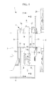
- FIG. 1 is a cross-sectional view of the relevant part of an internal combustion engine having a thrust bearing segment according to the first embodiment of the present invention, viewed from the left.
- FIG. 2 is a view taken along line II-II in FIG. 1 .
- FIG. 3 is a view taken along line III-III in FIG. 1 .
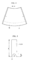
- FIG. 4 is a plan view of a thrust bearing segment (hereinbelow, a "thrust pad”) according to the first embodiment.
- FIG. 5 is a side view of the thrust pad according to the first embodiment.
- an internal combustion engine 1 having thrust pads of the present invention is, for example, a large diesel engine (crosshead diesel engine) employed as the main engine of a ship, and it is connected to a propeller shaft (not shown) having a propeller (not shown) fixed at one end, via an intermediate shaft (not shown).
- a crankshaft 2 that transmits the motive power of the internal combustion engine 1 to the propeller or the like is supported by a main bearing 4 and a thrust bearing 5, at a position behind a crank arm 3 located at the rearmost position (stern side).
- the main bearing 4 includes a main bearing housing (bedplate saddle) 7, which is cast integrally with or welded to a bedplate 6 and accommodates the crankshaft 2, and a main bearing cap (main-bearing pressing metal member) 8.
- the main bearing housing 7 includes a first housing 9 located on the front side (bow side) and a second housing 10 located on the rear side (stern side); a main-bearing lower metal member 12 that supports a journal 11 of the crankshaft 2 is fitted to the inner circumferential surface of the first housing 9, and a second main-bearing lower metal member 14 that supports a journal 13 of the crankshaft 2 is fitted to the inner circumferential surface of the second housing 10.
- the main bearing cap 8 includes a first cap 15 fixed to the first housing 9 so as to cover the upper part of the bottom of the first housing 9 with a plurality of main-bearing cap bolts (not shown) standing (installed upright) on the first housing 9 and attaching nuts (not shown) that have female screws threaded onto male screws provided on the main-bearing cap bolts, and a second cap 16 fixed to the second housing 10 so as to cover the upper part of the bottom of the second housing 10 with a plurality of main-bearing cap bolts (not shown) standing (installed upright) on the second housing 10 and attaching nuts (not shown) that have female screws threaded onto male screws provided on the main-bearing cap bolts.
- a main-bearing upper metal member (not shown) that supports the journal 11 of the crankshaft 2 is fitted to the inner circumferential surface of the first cap 15, and a second main-bearing upper metal member (not shown) that supports the journal 13 of the crankshaft 2 is fitted to the inner circumferential surface of the second cap 16.
- the thrust bearing 5 is accommodated in a recess 9a circumferentially formed in the inner circumferential portion of the first housing 9. Furthermore, the thrust bearing 5 includes a plurality of (five in the first embodiment) thrust pads 18 that support a front surface (an end surface on the bow side) 17a of a thrust collar (thrust cam) 17 circumferentially protruding radially outward in a ring-like shape from the outer circumferential surface of the crankshaft 2 located between the journal 11 and the journal 13, and thrust-pad pressing members 19 that limit (prevent) movement of the thrust pads 18 in the circumferential direction.
- thrust pads 18 that support a front surface (an end surface on the bow side) 17a of a thrust collar (thrust cam) 17 circumferentially protruding radially outward in a ring-like shape from the outer circumferential surface of the crankshaft 2 located between the journal 11 and the journal 13, and thrust-pad pressing members 19 that limit (prevent) movement of the thrust pads 18 in the circumferential direction.
- the thrust bearing 5 includes a plurality of (five in the first embodiment) thrust pads 20 that are accommodated in a recess 10a circumferentially formed in the inner circumferential portion of the second housing 10 and that support a rear surface (an end surface on the stern side) 17b of the thrust collar 17, and thrust-pad pressing members 21 that limit (prevent) movement of the thrust pads 20 in the circumferential direction.
- the thrust pads 18 are circumferentially arranged such that adjacent side surfaces are in contact with each other, and the side surfaces of the thrust pads 18 at both ends, more specifically, the middle portions of the side surfaces not in contact with the side surfaces of the adjacent thrust pads 18, are in contact with tip end surfaces of the thrust-pad pressing members 19. Furthermore, base end portions of the thrust-pad pressing members 19, which have an L shape in plan view, are fixed to the main bearing housing 7 with fastening means (for example, a plurality of bolts 22).
- the thrust pads 20 are circumferentially arranged such that adjacent side surfaces are in contact with each other, and the side surfaces of the thrust pads 20 at both ends, more specifically, the middle portions of the side surfaces not in contact with the side surfaces of the adjacent thrust pads 20, are in contact with tip end surfaces of the thrust-pad pressing members 21. Furthermore, base end portions of the thrust-pad pressing members 21, which have an L shape in plan view, are fixed to the main bearing housing 7 with fastening means (for example, a plurality of bolts 23). Note that the reference numeral 24 in FIGS. 1 and 3 denotes a flywheel (flywheel).
- Each of the thrust pads 18 and 20 according to the first embodiment has a plan-view shape as shown in FIG. 4 and a side-view shape (cross-sectional view) as shown in FIG. 5 , and the outer circumferential edge located on the radially outer side is circumferentially provided with a circumferential groove 32 machined (recessed) from a circumferential surface (outer circumferential surface) 31 toward the radially inward side and having a U shape in side view (cross-sectional view).
- the circumferential grooves 32 are formed so as to satisfy 0.05 ⁇ B/A ⁇ 0.45, where A is the length (in the radial direction) of the thrust pads 18 and 20, and B is the depth of the circumferential grooves 32.
- the thrust pads 18 and 20 because the provision of the circumferential grooves 32 makes the outer circumferential edges of the thrust pads 18 and 20 flexible, the stress concentrated on the outer circumferential edges of the thrust pads 18 and 20 can be reduced (distributed along the length direction (radial direction) of the thrust pads 18 and 20), the maximum surface pressure applied to each of the thrust pads 18 and 20 can be reduced, and hence, the load-bearing ability of the thrust bearing 5 can be improved.
- the reason why the stress is concentrated on the outer circumferential edges of the thrust pads 18 and 20 is that the main bearing housing 7 is joined to the bedplate 6 at the end farther from the crankshaft 2 (the lower end (lower portion) in FIG. 1 ), and the rigidity of the main bearing housing 7 supporting the thrust pads 18 and 20 increases as the distance from the crankshaft 2 increases.
- the recess does not need to be uniformly machined radially inward from the circumferential surface (outer circumferential surface) located on the radially outer side of the thrust collar 17 so that the cross-sectional shape thereof is uniform, as in the conventional type (the invention disclosed in PTL 1).
- the manufacturing processes of crankshafts and engines do not take a long time, and the engine manufacturing cost can be reduced.
- Thrust pads according to a second embodiment of the present invention will be described with reference to FIGS. 6 and 7.
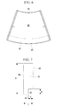
- FIG. 6 is a plan view of a thrust pad according to the second embodiment
- FIG. 7 is a side view of the thrust pad according to the second embodiment.
- Thrust pads 41 according to the second embodiment differ from those according to the above-described first embodiment in that they have a step portion 42, instead of the circumferential grooves 32. Because the other structural elements are the same as those according to the above-described first embodiment, descriptions thereof will be omitted here.
- the thrust pads 41 according to the second embodiment have a plan-view shape as shown in FIG. 6 and have a side-view shape (cross-sectional view) as shown in FIG. 7 .
- the outer circumferential edge of each thrust pad 41 located on the radially outer side is circumferentially provided with the step portion 42 extending radially inward from a circumferential surface (outer circumferential surface) 43, which is machined (recessed) from a non-pressure-receiving surface 45 (or a non-sliding surface, which is the surface opposite to the surface facing the front surface 17a or the rear surface 17b of the thrust collar 17 (see FIG.
- the step portion 42 is formed so as to satisfy 0.05 ⁇ B/A ⁇ 0.35 and 0.01 ⁇ C/T ⁇ 0.4, where A is the length (in the radial direction) of the thrust pad 41, B is the depth of the step portion 42, C is the width of the step portion 42, and T is the thickness of the thrust pad 41.
- the thrust pad 41 according to the second embodiment because the provision of the step portion 42 makes the outer circumferential edge of the thrust pad 41 flexible, the stress concentrated on the outer circumferential edge of the thrust pad 41 can be reduced (distributed along the length direction (radial direction) of the thrust pad 41). Accordingly, the maximum surface pressure applied to the thrust pad 41 is reduced, improving the load-bearing ability of the thrust bearing 5.
- the reason why the stress is concentrated on the outer circumferential edge of the thrust pad 41 is that the main bearing housing 7 is joined to the bedplate 6 at the end farther from the crankshaft 2 (the lower end (lower portion) in FIG. 1 ), and the rigidity of the main bearing housing 7 supporting the thrust pad 41 increases as the distance from the crankshaft 2 increases.
- the recess does not need to be uniformly machined radially inward from the circumferential surface (outer circumferential surface) located on the radially outer side of the thrust collar 17 so that the cross-sectional shape thereof is uniform, as in the conventional type (the invention disclosed in PTL 1).
- the manufacturing processes of crankshafts and engines do not take a long time, and the engine manufacturing cost can be reduced.
- Thrust pads according to a third embodiment of the present invention will be described with reference to FIGS. 8 and 9.
- FIG. 8 is a plan view of a thrust pad according to the third embodiment
- FIG. 9 is a side view of the thrust pad according to the third embodiment.
- Thrust pads 51 according to the third embodiment differ from those according to the above-described first embodiment in that they have a circumferential groove 52 instead of the circumferential grooves 32. Because the other structural elements are the same as those according to the above-described first embodiment, descriptions thereof will be omitted here.
- the thrust pads 51 according to the third embodiment have a plan-view shape as shown in FIG. 8 and have a side-view shape (cross-sectional view) as shown in FIG. 9 .
- the inner circumferential edge of each thrust pad 51 located on the radially inner side is circumferentially provided with a circumferential groove 52 machined (recessed) from the circumferential surface (inner circumferential surface) 53 toward the radially outer side and has a U shape in side view (cross-sectional view).
- the circumferential groove 52 is formed so as to satisfy 0.1 ⁇ B/A ⁇ 0.5, where A is the length (in the radial direction) of the thrust pad 51, and B is the depth of the circumferential groove 52.
- the load point on the main bearing housing 7 can be moved toward the outer circumferential edge of the thrust pad 51 (radially outward). Accordingly, the maximum surface pressure applied to the thrust pad 51 is reduced, improving the load-bearing ability of the thrust bearing 5.
- the reason why the maximum surface pressure applied to each thrust pad 51 can be reduced by moving the load point on the main bearing housing 7 toward the outer circumferential edge of the thrust pad 51 is that, because the main bearing housing 7 is joined to the bedplate 6 at the end farther from the crankshaft 2 (the lower end (lower portion) in FIG.
- the recess does not need to be uniformly machined radially inward from the circumferential surface (outer circumferential surface) located on the radially outer side of the thrust collar 17 so that the cross-sectional shape thereof is uniform, as in the conventional type (the invention disclosed in PTL 1).
- the manufacturing processes of crankshafts and engines do not take a long time, and the engine manufacturing cost can be reduced.
- Thrust pads according to a fourth embodiment of the present invention will be described with reference to FIGS. 10 and 11.
- FIG. 10 is a plan view of a thrust pad according to the fourth embodiment
- FIG. 11 is a side view of the thrust pad according to the fourth embodiment.
- Thrust pads 61 according to the fourth embodiment differ from those according to the above-described first embodiment in that they have a step portion 62, instead of the circumferential grooves 32. Because the other structural elements are the same as those according to the above-described first embodiment, descriptions thereof will be omitted here.
- the thrust pads 61 according to the fourth embodiment have a plan-view shape as shown in FIG. 10 and have a side-view shape (cross-sectional view) as shown in FIG. 11 .
- the inner circumferential edge of each thrust pad 61 located on the radially inner side is circumferentially provided with the step portion 62 extending radially outward from a circumferential surface (inner circumferential surface) 63, which is machined (recessed) from the non-pressure-receiving surface 45 (or the non-sliding surface, which is the surface opposite to the surface facing the front surface 17a or the rear surface 17b of the thrust collar 17 (see FIG.
- the step portion 62 is formed so as to satisfy 0.15 ⁇ B/A ⁇ 0.35 and 0.1 ⁇ C/T ⁇ 0.4, where A is the length (in the radial direction) of the thrust pad 61, B is the depth of the step portion 62, C is the width of the step portion 62, and T is the thickness of the thrust pad 61.
- the load point on the main bearing housing 7 can be moved toward the outer circumferential edge (radially outer side) of the thrust pad 61. Accordingly, the maximum surface pressure applied to the thrust pad 61 is reduced, improving the load-bearing ability of the thrust bearing 5.
- the reason why the maximum surface pressure applied to each thrust pad 61 can be reduced by moving the load point on the main bearing housing 7 toward the outer circumferential edge of the thrust pad 61 is that, because the main bearing housing 7 is joined to the bedplate 6 at the end farther from the crankshaft 2 (the lower end (lower portion) in FIG.
- the recess does not need to be uniformly machined radially inward from the circumferential surface (outer circumferential surface) located on the radially outer side of the thrust collar 17 so that the cross-sectional shape thereof is uniform, as in the conventional type (the invention disclosed in PTL 1).
- the manufacturing processes of crankshafts and engines do not take a long time, and the engine manufacturing cost can be reduced.
- the thrust bearing 5 having the thrust pads according to the embodiments of the present invention achieves an improved load-bearing ability even when the size of the thrust pads is the same as that of the conventional thrust pads, it can be applied to a large internal combustion engine (for example, a diesel engine) having a larger output than a conventional internal combustion engine, without increasing the size.
- the thrust pads when subjected to the same load as before, the thrust pads may have a smaller size than the conventional thrust pads. Thus, the size and weight of the thrust bearing 5 can be reduced.
- the thrust pads when subjected to the same load as before, may have a smaller size than the conventional thrust pads.
- the sizes and weights of the main bearing housing 7 and the bedplate 6 can be reduced.
- the present invention is not limited to the above-described embodiments, and it can be variously changed or modified within a scope not departing from the spirit of the present invention.
- the present invention may be embodied by combining the above-described first embodiment and the third embodiment or the fourth embodiment, or may be embodied by combining the above-described second embodiment and the third embodiment or the fourth embodiment.
- cross-sectional shape of the circumferential grooves 32 and 52 is not limited to a U shape, and the cross-sectional shape of the step portions 42 and 62 is not limited to an L shape; any shape that achieves the same advantage may be employed.
Landscapes
- Engineering & Computer Science (AREA)
- General Engineering & Computer Science (AREA)
- Mechanical Engineering (AREA)
- Chemical & Material Sciences (AREA)
- Combustion & Propulsion (AREA)
- Sliding-Contact Bearings (AREA)
- Shafts, Cranks, Connecting Bars, And Related Bearings (AREA)
- Cylinder Crankcases Of Internal Combustion Engines (AREA)
Abstract
A thrust bearing segment that can improve the load-bearing ability of a thrust bearing is provided. A thrust pad (18) supports a thrust collar (17) while resisting a load in a rotation axis direction acting on the thrust collar (17) provided on the crankshaft (2) and has a recess circumferentially provided in at least one of an outer circumferential edge having an outer circumferential surface facing radially outward with respect to the rotation axis and an inner circumferential edge having an inner circumferential surface facing radially inward with respect to the rotation axis.
Description
- The present invention relates to a thrust bearing segment used in, for example, a thrust bearing that constitutes a large marine diesel engine, to a thrust bearing, and to an internal combustion engine.
- A thrust bearing that constitutes a large marine diesel engine and is disclosed in, for example,
PTL 1 is known. - {PTL 1} The Publication of Japanese Patent No.
3689378 - In the invention disclosed in
PTL 1, a recess 28 having an arch shape in cross-sectional view is circumferentially provided in an outer circumferential edge of a thrust collar 14, thereby improving the load-bearing ability of a thrust bearing 7.
However, in the invention disclosed inPTL 1, the recess 28 needs to be uniformly machined out of a circumferential surface (outer circumferential surface) located on the radially outer side of the thrust collar 14 toward the radially inward side so that the cross-sectional shape thereof is uniform. Thus, in large marine diesel engines, the manufacturing processes of crankshafts and engines require a long time, leading to a problem of high engine manufacturing costs. - The present invention has been made in view of the above-described circumstances, and an object thereof is to provide a thrust bearing segment that can improve the load-bearing ability of a thrust bearing and to provide a thrust bearing and an internal combustion engine.
- To overcome the above-described problem, the present invention employs the following solutions.
A thrust bearing segment according to the present invention is a thrust bearing segment that supports a thrust collar while resisting a load in a rotation axis direction acting on the thrust collar provided on a crankshaft. The thrust bearing segment has a recess circumferentially provided in at least one of an outer circumferential edge having an outer circumferential surface facing radially outward with respect to the rotation axis and an inner circumferential edge having an inner circumferential surface facing radially inward with respect to the rotation axis. - In the thrust bearing segment according to the first aspect of the present invention, the recess is provided in the outer circumferential edge, and the recess is a circumferential groove having a U-shaped cross section in the radial direction.
- In a thrust bearing segment according to a second aspect of the present invention, the recess is provided in the outer circumferential edge, and the recess is a step portion provided on a surface not in contact with the thrust collar and having an L-shaped cross section in the radial direction.
- In the thrust bearing segment according to the first aspect or second aspect of the present invention, it is more preferable that the recess be provided in the inner circumferential edge, and the recess be a circumferential groove having a U-shaped cross section in the radial direction.
- In the thrust bearing segment according to the first aspect or second aspect of the present invention, it is more preferable that the recess be provided in the inner circumferential edge, and the recess be a step portion provided on a surface not in contact with the thrust collar and having an L-shaped cross section in the radial direction.
- In the thrust bearing segment according to a third aspect of the present invention, the recess is provided in the inner circumferential edge, and the recess is a circumferential groove having a U-shaped cross section in the radial direction.
- In the thrust bearing segment according to a fourth aspect of the present invention, the recess is provided in the inner circumferential edge, and the recess is a step portion provided on a surface not in contact with the thrust collar and having an L-shaped cross section in the radial direction.
- A thrust bearing of the present invention includes any one of the above-described thrust bearing segments.
- Because the thrust bearing of the present invention achieves an improved load-bearing ability even when the size of the thrust bearing segment is the same as that of the conventional thrust bearing segment, it can be applied to a large internal combustion engine (for example, a diesel engine) having a larger output than a conventional internal combustion engine, without increasing the size.
On the other hand, when subjected to the same load as before, the thrust bearing segment may have a smaller size than the conventional thrust bearing segment. Thus, the size and weight of the thrust bearing can be reduced. - The internal combustion engine of the present invention has the above-described thrust bearing.
- Because, in the internal combustion engine of the present invention, the thrust bearing segment may have a smaller size than the conventional thrust bearing segment when subjected to the same load as before, the size and weight of a main bearing housing and a bedplate, which support the thrust bearing segment, can be reduced.
- The thrust bearing segment, the thrust bearing, and the internal combustion engine of the present invention achieve an advantage of providing improved load-bearing ability of the thrust bearing.
-
- {
FIG. 1} FIG. 1 is a cross-sectional view of the relevant part of an internal combustion engine having a thrust bearing segment according to a first embodiment of the present invention, viewed from the left. - {
FIG. 2} FIG. 2 is a view taken along line II-II inFIG. 1 . - {
FIG. 3} FIG. 3 is a view taken along line III-III inFIG. 1 . - {
FIG. 4} FIG. 4 is a plan view of a thrust pad (thrust bearing segment) according to the first embodiment of the present invention. - {
FIG. 5} FIG. 5 is a side view of the thrust pad (thrust bearing segment) according to the first embodiment of the present invention. - {
FIG. 6} FIG. 6 is a plan view of a thrust pad (thrust bearing segment) according to a second embodiment of the present invention. - {
FIG. 7} FIG. 7 is a side view of the thrust pad (thrust bearing segment) according to the second embodiment of the present invention. - {
FIG. 8} FIG. 8 is a plan view of a thrust pad (thrust bearing segment) according to a third embodiment of the present invention. - {
FIG. 9} FIG. 9 is a side view of the thrust pad (thrust bearing segment) according to the third embodiment of the present invention. - {
FIG. 10} FIG. 10 is a plan view of a thrust pad (thrust bearing segment) according to a fourth embodiment of the present invention. - {
FIG. 11} FIG. 11 is a side view of the thrust pad (thrust bearing segment) according to the fourth embodiment of the present invention. - A thrust bearing segment according to a first embodiment of the present invention will be described below with reference to
FIGS. 1 to 5 .
FIG. 1 is a cross-sectional view of the relevant part of an internal combustion engine having a thrust bearing segment according to the first embodiment of the present invention, viewed from the left.FIG. 2 is a view taken along line II-II inFIG. 1 .FIG. 3 is a view taken along line III-III inFIG. 1 .FIG. 4 is a plan view of a thrust bearing segment (hereinbelow, a "thrust pad") according to the first embodiment.FIG. 5 is a side view of the thrust pad according to the first embodiment. - As shown in
FIG. 1 , aninternal combustion engine 1 having thrust pads of the present invention is, for example, a large diesel engine (crosshead diesel engine) employed as the main engine of a ship, and it is connected to a propeller shaft (not shown) having a propeller (not shown) fixed at one end, via an intermediate shaft (not shown).
Acrankshaft 2 that transmits the motive power of theinternal combustion engine 1 to the propeller or the like is supported by a main bearing 4 and a thrust bearing 5, at a position behind acrank arm 3 located at the rearmost position (stern side). - The main bearing 4 includes a main bearing housing (bedplate saddle) 7, which is cast integrally with or welded to a
bedplate 6 and accommodates thecrankshaft 2, and a main bearing cap (main-bearing pressing metal member) 8.
The main bearinghousing 7 includes afirst housing 9 located on the front side (bow side) and asecond housing 10 located on the rear side (stern side); a main-bearinglower metal member 12 that supports ajournal 11 of thecrankshaft 2 is fitted to the inner circumferential surface of thefirst housing 9, and a second main-bearing lower metal member 14 that supports ajournal 13 of thecrankshaft 2 is fitted to the inner circumferential surface of thesecond housing 10. - On the other hand, the
main bearing cap 8 includes afirst cap 15 fixed to thefirst housing 9 so as to cover the upper part of the bottom of thefirst housing 9 with a plurality of main-bearing cap bolts (not shown) standing (installed upright) on thefirst housing 9 and attaching nuts (not shown) that have female screws threaded onto male screws provided on the main-bearing cap bolts, and asecond cap 16 fixed to thesecond housing 10 so as to cover the upper part of the bottom of thesecond housing 10 with a plurality of main-bearing cap bolts (not shown) standing (installed upright) on thesecond housing 10 and attaching nuts (not shown) that have female screws threaded onto male screws provided on the main-bearing cap bolts. A main-bearing upper metal member (not shown) that supports thejournal 11 of thecrankshaft 2 is fitted to the inner circumferential surface of thefirst cap 15, and a second main-bearing upper metal member (not shown) that supports thejournal 13 of thecrankshaft 2 is fitted to the inner circumferential surface of thesecond cap 16. - The thrust bearing 5 is accommodated in a
recess 9a circumferentially formed in the inner circumferential portion of thefirst housing 9. Furthermore, the thrust bearing 5 includes a plurality of (five in the first embodiment)thrust pads 18 that support a front surface (an end surface on the bow side) 17a of a thrust collar (thrust cam) 17 circumferentially protruding radially outward in a ring-like shape from the outer circumferential surface of thecrankshaft 2 located between thejournal 11 and thejournal 13, and thrust-pad pressing members 19 that limit (prevent) movement of thethrust pads 18 in the circumferential direction. Furthermore, the thrust bearing 5 includes a plurality of (five in the first embodiment)thrust pads 20 that are accommodated in arecess 10a circumferentially formed in the inner circumferential portion of thesecond housing 10 and that support a rear surface (an end surface on the stern side) 17b of thethrust collar 17, and thrust-pad pressing members 21 that limit (prevent) movement of thethrust pads 20 in the circumferential direction. - As shown in
FIG. 2 , thethrust pads 18 are circumferentially arranged such that adjacent side surfaces are in contact with each other, and the side surfaces of thethrust pads 18 at both ends, more specifically, the middle portions of the side surfaces not in contact with the side surfaces of theadjacent thrust pads 18, are in contact with tip end surfaces of the thrust-pad pressing members 19. Furthermore, base end portions of the thrust-pad pressing members 19, which have an L shape in plan view, are fixed to the main bearinghousing 7 with fastening means (for example, a plurality of bolts 22). - On the other hand, as shown in
FIG. 3 , similarly to thethrust pads 18, thethrust pads 20 are circumferentially arranged such that adjacent side surfaces are in contact with each other, and the side surfaces of thethrust pads 20 at both ends, more specifically, the middle portions of the side surfaces not in contact with the side surfaces of theadjacent thrust pads 20, are in contact with tip end surfaces of the thrust-pad pressing members 21. Furthermore, base end portions of the thrust-pad pressing members 21, which have an L shape in plan view, are fixed to the main bearinghousing 7 with fastening means (for example, a plurality of bolts 23).
Note that thereference numeral 24 inFIGS. 1 and3 denotes a flywheel (flywheel). - Each of the
thrust pads FIG. 4 and a side-view shape (cross-sectional view) as shown inFIG. 5 , and the outer circumferential edge located on the radially outer side is circumferentially provided with acircumferential groove 32 machined (recessed) from a circumferential surface (outer circumferential surface) 31 toward the radially inward side and having a U shape in side view (cross-sectional view).
Thecircumferential grooves 32 are formed so as to satisfy 0.05≤B/A≤0.45, where A is the length (in the radial direction) of thethrust pads circumferential grooves 32. - In the
thrust pads circumferential grooves 32 makes the outer circumferential edges of thethrust pads thrust pads thrust pads 18 and 20), the maximum surface pressure applied to each of thethrust pads
Note that the reason why the stress is concentrated on the outer circumferential edges of thethrust pads main bearing housing 7 is joined to thebedplate 6 at the end farther from the crankshaft 2 (the lower end (lower portion) inFIG. 1 ), and the rigidity of themain bearing housing 7 supporting thethrust pads crankshaft 2 increases. - Furthermore, in the
thrust pads thrust collar 17 so that the cross-sectional shape thereof is uniform, as in the conventional type (the invention disclosed in PTL 1). Thus, even in large marine diesel engines, the manufacturing processes of crankshafts and engines do not take a long time, and the engine manufacturing cost can be reduced. - Thrust pads according to a second embodiment of the present invention will be described with reference to
FIGS. 6 and 7. FIG. 6 is a plan view of a thrust pad according to the second embodiment, andFIG. 7 is a side view of the thrust pad according to the second embodiment.
Thrust pads 41 according to the second embodiment differ from those according to the above-described first embodiment in that they have astep portion 42, instead of thecircumferential grooves 32. Because the other structural elements are the same as those according to the above-described first embodiment, descriptions thereof will be omitted here. - The
thrust pads 41 according to the second embodiment have a plan-view shape as shown inFIG. 6 and have a side-view shape (cross-sectional view) as shown inFIG. 7 . The outer circumferential edge of eachthrust pad 41 located on the radially outer side is circumferentially provided with thestep portion 42 extending radially inward from a circumferential surface (outer circumferential surface) 43, which is machined (recessed) from a non-pressure-receiving surface 45 (or a non-sliding surface, which is the surface opposite to the surface facing thefront surface 17a or therear surface 17b of the thrust collar 17 (seeFIG. 1 ), i.e., a pressure-receiving surface or a sliding surface 44) toward the pressure-receivingsurface 44 and has an L shape (rectangular shape) in side view (cross-sectional view).
Thestep portion 42 is formed so as to satisfy 0.05≤B/A≤0.35 and 0.01≤C/T≤0.4, where A is the length (in the radial direction) of thethrust pad 41, B is the depth of thestep portion 42, C is the width of thestep portion 42, and T is the thickness of thethrust pad 41. - In the
thrust pad 41 according to the second embodiment, because the provision of thestep portion 42 makes the outer circumferential edge of thethrust pad 41 flexible, the stress concentrated on the outer circumferential edge of thethrust pad 41 can be reduced (distributed along the length direction (radial direction) of the thrust pad 41). Accordingly, the maximum surface pressure applied to thethrust pad 41 is reduced, improving the load-bearing ability of thethrust bearing 5.
Note that the reason why the stress is concentrated on the outer circumferential edge of thethrust pad 41 is that themain bearing housing 7 is joined to thebedplate 6 at the end farther from the crankshaft 2 (the lower end (lower portion) inFIG. 1 ), and the rigidity of themain bearing housing 7 supporting thethrust pad 41 increases as the distance from thecrankshaft 2 increases. - Furthermore, in the
thrust pads 41 according to the second embodiment, the recess does not need to be uniformly machined radially inward from the circumferential surface (outer circumferential surface) located on the radially outer side of thethrust collar 17 so that the cross-sectional shape thereof is uniform, as in the conventional type (the invention disclosed in PTL 1). Thus, even in large marine diesel engines, the manufacturing processes of crankshafts and engines do not take a long time, and the engine manufacturing cost can be reduced. - Thrust pads according to a third embodiment of the present invention will be described with reference to
FIGS. 8 and 9. FIG. 8 is a plan view of a thrust pad according to the third embodiment, andFIG. 9 is a side view of the thrust pad according to the third embodiment.
Thrust pads 51 according to the third embodiment differ from those according to the above-described first embodiment in that they have acircumferential groove 52 instead of thecircumferential grooves 32. Because the other structural elements are the same as those according to the above-described first embodiment, descriptions thereof will be omitted here. - The
thrust pads 51 according to the third embodiment have a plan-view shape as shown inFIG. 8 and have a side-view shape (cross-sectional view) as shown inFIG. 9 . The inner circumferential edge of eachthrust pad 51 located on the radially inner side is circumferentially provided with acircumferential groove 52 machined (recessed) from the circumferential surface (inner circumferential surface) 53 toward the radially outer side and has a U shape in side view (cross-sectional view).
Thecircumferential groove 52 is formed so as to satisfy 0.1≤B/A≤0.5, where A is the length (in the radial direction) of thethrust pad 51, and B is the depth of thecircumferential groove 52. - In the
thrust pad 51 according to the third embodiment, because the provision of thecircumferential groove 52 makes the inner circumferential edge of thethrust pad 51 flexible, the load point on themain bearing housing 7 can be moved toward the outer circumferential edge of the thrust pad 51 (radially outward). Accordingly, the maximum surface pressure applied to thethrust pad 51 is reduced, improving the load-bearing ability of thethrust bearing 5.
Note that the reason why the maximum surface pressure applied to eachthrust pad 51 can be reduced by moving the load point on themain bearing housing 7 toward the outer circumferential edge of thethrust pad 51 is that, because themain bearing housing 7 is joined to thebedplate 6 at the end farther from the crankshaft 2 (the lower end (lower portion) inFIG. 1 ), by moving the load point on themain bearing housing 7 toward the outer circumferential edge of thethrust pad 51, thethrust pad 51 is supported by themain bearing housing 7 on the farther side from thecrankshaft 2, which has a higher rigidity, reducing the displacement (inclination) of themain bearing housing 7. - Furthermore, in the
thrust pads 51 according to the third embodiment, the recess does not need to be uniformly machined radially inward from the circumferential surface (outer circumferential surface) located on the radially outer side of thethrust collar 17 so that the cross-sectional shape thereof is uniform, as in the conventional type (the invention disclosed in PTL 1). Thus, even in large marine diesel engines, the manufacturing processes of crankshafts and engines do not take a long time, and the engine manufacturing cost can be reduced. - Thrust pads according to a fourth embodiment of the present invention will be described with reference to
FIGS. 10 and 11. FIG. 10 is a plan view of a thrust pad according to the fourth embodiment, andFIG. 11 is a side view of the thrust pad according to the fourth embodiment.
Thrust pads 61 according to the fourth embodiment differ from those according to the above-described first embodiment in that they have astep portion 62, instead of thecircumferential grooves 32. Because the other structural elements are the same as those according to the above-described first embodiment, descriptions thereof will be omitted here. - The
thrust pads 61 according to the fourth embodiment have a plan-view shape as shown inFIG. 10 and have a side-view shape (cross-sectional view) as shown inFIG. 11 . The inner circumferential edge of eachthrust pad 61 located on the radially inner side is circumferentially provided with thestep portion 62 extending radially outward from a circumferential surface (inner circumferential surface) 63, which is machined (recessed) from the non-pressure-receiving surface 45 (or the non-sliding surface, which is the surface opposite to the surface facing thefront surface 17a or therear surface 17b of the thrust collar 17 (seeFIG. 1 ), i.e., the pressure-receiving surface or the sliding surface 44) toward the pressure-receivingsurface 44 and has an L shape (rectangular shape) in side view (cross-sectional view).
Thestep portion 62 is formed so as to satisfy 0.15≤B/A≤0.35 and 0.1≤C/T≤0.4, where A is the length (in the radial direction) of thethrust pad 61, B is the depth of thestep portion 62, C is the width of thestep portion 62, and T is the thickness of thethrust pad 61. - In the
thrust pad 61 according to the fourth embodiment, because the provision of thestep portion 62 makes the inner circumferential edge of thethrust pad 61 flexible, the load point on themain bearing housing 7 can be moved toward the outer circumferential edge (radially outer side) of thethrust pad 61. Accordingly, the maximum surface pressure applied to thethrust pad 61 is reduced, improving the load-bearing ability of thethrust bearing 5.
Note that the reason why the maximum surface pressure applied to eachthrust pad 61 can be reduced by moving the load point on themain bearing housing 7 toward the outer circumferential edge of thethrust pad 61 is that, because themain bearing housing 7 is joined to thebedplate 6 at the end farther from the crankshaft 2 (the lower end (lower portion) inFIG. 1 ), by moving the load point on themain bearing housing 7 toward the outer circumferential edge of thethrust pad 61, thethrust pad 61 is supported by themain bearing housing 7 on the farther side from thecrankshaft 2, which has a higher rigidity, reducing the displacement (inclination) of themain bearing housing 7. - Furthermore, in the
thrust pads 61 according to the fourth embodiment, the recess does not need to be uniformly machined radially inward from the circumferential surface (outer circumferential surface) located on the radially outer side of thethrust collar 17 so that the cross-sectional shape thereof is uniform, as in the conventional type (the invention disclosed in PTL 1). Thus, even in large marine diesel engines, the manufacturing processes of crankshafts and engines do not take a long time, and the engine manufacturing cost can be reduced. - Because the
thrust bearing 5 having the thrust pads according to the embodiments of the present invention achieves an improved load-bearing ability even when the size of the thrust pads is the same as that of the conventional thrust pads, it can be applied to a large internal combustion engine (for example, a diesel engine) having a larger output than a conventional internal combustion engine, without increasing the size.
On the other hand, when subjected to the same load as before, the thrust pads may have a smaller size than the conventional thrust pads. Thus, the size and weight of thethrust bearing 5 can be reduced. - In the
internal combustion engine 1 according to the embodiments of the present invention, when subjected to the same load as before, the thrust pads may have a smaller size than the conventional thrust pads. Thus, the sizes and weights of themain bearing housing 7 and thebedplate 6 can be reduced. - Note that the present invention is not limited to the above-described embodiments, and it can be variously changed or modified within a scope not departing from the spirit of the present invention.
For example, the present invention may be embodied by combining the above-described first embodiment and the third embodiment or the fourth embodiment, or may be embodied by combining the above-described second embodiment and the third embodiment or the fourth embodiment. - Furthermore, the cross-sectional shape of the
circumferential grooves step portions -
- 1: large diesel engine (internal combustion engine)
- 2: crankshaft
- 5: thrust bearing
- 17: thrust collar
- 18: thrust pad (thrust bearing segment)
- 20: thrust pad (thrust bearing segment)
- 32: circumferential groove
- 41: thrust pad (thrust bearing segment)
- 42: step portion
- 44: pressure-receiving surface
- 45: non-pressure-receiving surface
- 51: thrust pad (thrust bearing segment)
- 52: circumferential groove
- 61: thrust pad (thrust bearing segment)
- 62: step portion
Claims (9)
- A thrust bearing segment that supports a thrust collar while resisting a load in a rotation axis direction acting on the thrust collar provided on a crankshaft,
wherein the thrust bearing segment has a recess circumferentially provided in at least one of an outer circumferential edge having an outer circumferential surface facing radially outward with respect to the rotation axis and an inner circumferential edge having an inner circumferential surface facing radially inward with respect to the rotation axis. - The thrust bearing segment according to Claim 1, wherein the recess is provided in the outer circumferential edge, and the recess is a circumferential groove having a U-shaped cross section in the radial direction.
- The thrust bearing segment according to Claim 1, wherein the recess is provided in the outer circumferential edge, and the recess is a step portion provided on a surface not in contact with the thrust collar and having an L-shaped cross section in the radial direction.
- The thrust bearing segment according to Claim 2 or 3, wherein the recess is provided in the inner circumferential edge, and the recess is a circumferential groove having a U-shaped cross section in the radial direction.
- The thrust bearing segment according to Claim 2 or 3, wherein the recess is provided in the inner circumferential edge, and the recess is a step portion provided on a surface not in contact with the thrust collar and having an L-shaped cross section in the radial direction.
- The thrust bearing segment according to Claim 1, wherein the recess is provided in the inner circumferential edge, and the recess is a circumferential groove having a U-shaped cross section in the radial direction.
- The thrust bearing segment according to Claim 1, wherein the recess is provided in the inner circumferential edge, and the recess is a step portion provided on a surface not in contact with the thrust collar and having an L-shaped cross section in the radial direction.
- A thrust bearing comprising the thrust bearing segment according to any one of Claims 1 to 7.
- An internal combustion engine comprising the thrust bearing according to Claim 8.
Applications Claiming Priority (2)
| Application Number | Priority Date | Filing Date | Title |
|---|---|---|---|
| JP2010046688A JP2011179661A (en) | 2010-03-03 | 2010-03-03 | Thrust bearing segment |
| PCT/JP2011/054872 WO2011108630A1 (en) | 2010-03-03 | 2011-03-03 | Thrust bearing segment, thrust bearing, and internal combustion engine |
Publications (1)
| Publication Number | Publication Date |
|---|---|
| EP2543899A1 true EP2543899A1 (en) | 2013-01-09 |
Family
ID=44542277
Family Applications (1)
| Application Number | Title | Priority Date | Filing Date |
|---|---|---|---|
| EP11750739A Withdrawn EP2543899A1 (en) | 2010-03-03 | 2011-03-03 | Thrust bearing segment, thrust bearing, and internal combustion engine |
Country Status (5)
| Country | Link |
|---|---|
| EP (1) | EP2543899A1 (en) |
| JP (1) | JP2011179661A (en) |
| KR (1) | KR20120097409A (en) |
| CN (1) | CN102725548A (en) |
| WO (1) | WO2011108630A1 (en) |
Families Citing this family (1)
| Publication number | Priority date | Publication date | Assignee | Title |
|---|---|---|---|---|
| CN104279224A (en) * | 2014-09-29 | 2015-01-14 | 无锡明珠钢球有限公司 | Thrust ball bearing |
Family Cites Families (5)
| Publication number | Priority date | Publication date | Assignee | Title |
|---|---|---|---|---|
| SU1296755A1 (en) * | 1985-07-18 | 1987-03-15 | Производственное объединение "Невский завод" им.В.И.Ленина | Turbomachine thrust bearing |
| DK169927B1 (en) * | 1992-02-19 | 1995-04-03 | Man B & W Diesel Gmbh | Piston engine with a Michell-type thrust bearing |
| DK200100412A (en) * | 2001-03-12 | 2002-09-13 | Man B & W Diesel As | Combustion engine for propeller shaft drive |
| JP2002372030A (en) * | 2001-06-13 | 2002-12-26 | Honda Motor Co Ltd | Crankshaft bearing device |
| DE10136638C2 (en) * | 2001-07-26 | 2003-11-20 | Man B&W Diesel A/S, Copenhagen Sv | reciprocating engine |
-
2010
- 2010-03-03 JP JP2010046688A patent/JP2011179661A/en active Pending
-
2011
- 2011-03-03 WO PCT/JP2011/054872 patent/WO2011108630A1/en not_active Ceased
- 2011-03-03 EP EP11750739A patent/EP2543899A1/en not_active Withdrawn
- 2011-03-03 KR KR1020127019477A patent/KR20120097409A/en not_active Ceased
- 2011-03-03 CN CN2011800070352A patent/CN102725548A/en active Pending
Non-Patent Citations (1)
| Title |
|---|
| See references of WO2011108630A1 * |
Also Published As
| Publication number | Publication date |
|---|---|
| KR20120097409A (en) | 2012-09-03 |
| CN102725548A (en) | 2012-10-10 |
| JP2011179661A (en) | 2011-09-15 |
| WO2011108630A1 (en) | 2011-09-09 |
Similar Documents
| Publication | Publication Date | Title |
|---|---|---|
| EP1886033B1 (en) | Thrust bearing | |
| US6481895B2 (en) | Flange bearing | |
| US8757888B2 (en) | Shaft/bearing arrangement | |
| US10408256B2 (en) | Half thrust bearing | |
| EP4624740A2 (en) | Piston | |
| US20100247011A1 (en) | Bearing device | |
| US20110174153A1 (en) | Piston for an internal combustion engine | |
| US10550879B2 (en) | Thrust washer | |
| US9243583B2 (en) | Piston for an internal combustion engine | |
| US10233967B2 (en) | Half thrust bearing | |
| WO2016157575A1 (en) | Connecting rod and cross-head type engine provided with same | |
| JP5674893B2 (en) | Crankshaft, bearing assembly, and large multi-cylinder two-stroke diesel engine | |
| JP5545553B2 (en) | Thrust bearing | |
| WO2008072548A1 (en) | Slide bearing | |
| US8360026B2 (en) | Pin boss and piston provided with it, for an internal combustion engine | |
| JP5036604B2 (en) | Crankshaft bearing structure | |
| US6485183B1 (en) | Plain bearing for connecting rods | |
| WO2011108630A1 (en) | Thrust bearing segment, thrust bearing, and internal combustion engine | |
| US9416817B2 (en) | Crankshaft bearing assembly | |
| JP7722221B2 (en) | Reciprocating unit | |
| EP4095404B1 (en) | Internal combustion engine and vehicle | |
| JP2004019800A (en) | Thrust washer | |
| JP3689378B2 (en) | Internal combustion engine that drives the propeller shaft | |
| JP7652042B2 (en) | Internal combustion engine | |
| JP2017053291A (en) | Radial piston hydraulic machine and wind power generator |
Legal Events
| Date | Code | Title | Description |
|---|---|---|---|
| PUAI | Public reference made under article 153(3) epc to a published international application that has entered the european phase |
Free format text: ORIGINAL CODE: 0009012 |
|
| 17P | Request for examination filed |
Effective date: 20120723 |
|
| AK | Designated contracting states |
Kind code of ref document: A1 Designated state(s): AL AT BE BG CH CY CZ DE DK EE ES FI FR GB GR HR HU IE IS IT LI LT LU LV MC MK MT NL NO PL PT RO RS SE SI SK SM TR |
|
| STAA | Information on the status of an ep patent application or granted ep patent |
Free format text: STATUS: THE APPLICATION HAS BEEN WITHDRAWN |
|
| 18W | Application withdrawn |
Effective date: 20130131 |