EP2543851A1 - Gas turbine engine - Google Patents
Gas turbine engine Download PDFInfo
- Publication number
- EP2543851A1 EP2543851A1 EP11750330A EP11750330A EP2543851A1 EP 2543851 A1 EP2543851 A1 EP 2543851A1 EP 11750330 A EP11750330 A EP 11750330A EP 11750330 A EP11750330 A EP 11750330A EP 2543851 A1 EP2543851 A1 EP 2543851A1
- Authority
- EP
- European Patent Office
- Prior art keywords
- rotor
- gas turbine
- turbine engine
- pipe unit
- compressor
- Prior art date
- Legal status (The legal status is an assumption and is not a legal conclusion. Google has not performed a legal analysis and makes no representation as to the accuracy of the status listed.)
- Withdrawn
Links
Images





Classifications
-
- F—MECHANICAL ENGINEERING; LIGHTING; HEATING; WEAPONS; BLASTING
- F01—MACHINES OR ENGINES IN GENERAL; ENGINE PLANTS IN GENERAL; STEAM ENGINES
- F01D—NON-POSITIVE DISPLACEMENT MACHINES OR ENGINES, e.g. STEAM TURBINES
- F01D5/00—Blades; Blade-carrying members; Heating, heat-insulating, cooling or antivibration means on the blades or the members
- F01D5/02—Blade-carrying members, e.g. rotors
- F01D5/08—Heating, heat-insulating or cooling means
- F01D5/085—Heating, heat-insulating or cooling means cooling fluid circulating inside the rotor
Definitions
- the present invention relates to a gas turbine engine including a pipe for use as a passage of a cooling medium, a cable layout member, or the like.
- Patent Literature 1 Japanese Laid-Open Patent Application Publication No. Hei. 11-257012
- a compressor rotor or a turbine rotor in a gas turbine engine is assembled in such a manner that a plurality of rotor segments are coupled together in a center axis direction thereof. Therefore, it is difficult to form a pipe in an inner space of the rotor integrally with the rotor and fasten the pipe to the rotor by means of a fastener member such as a bolt, in terms of productivity. Therefore, it is necessary to insert the pipe into a through-hole provided inside of the rotor before or after assembling of the rotor. In this case, however, a small gap is unavoidably formed between the pipe and a peripheral wall of the through-hole. As a result, when the rotor is rotating at a high speed, the pipe whirls inside the through-hole, which causes a problem that efficiency and life of the gas turbine engine are reduced.
- the present invention is directed to solving the above mentioned problem, and an object of the present invention is to provide a gas turbine engine which can prevent whirl of a pipe provided in an inner space of a rotor to transport a cooling medium or lay out cables, for example, and thus can achieve higher performance and reliability.
- a gas turbine engine of the present invention comprises a hollow rotor including a plurality of rotor segments coupled together in a direction of its center axis and defining at least one of a compressor and a turbine; and a pipe unit inserted into an inner space of the rotor in the center axis direction, wherein a weight distribution of the pipe unit within an axial transverse section is eccentric with respect to the center axis of the rotor.
- the pipe unit is provided in the inner space of the hollow rotor and is utilized as a cooling medium passage or a cable layout member, higher performance and higher functionality of the gas turbine engine can be achieved, while suppressing an increase in a dimension of the overall gas turbine engine. Since the weight distribution of the pipe unit is made eccentric, the pipe unit is displaced only in a specified direction with respect to the rotor, during rotation of the rotor. This makes it possible to suppress the pipe unit from whirling inside of the rotor. Therefore, reliability of the gas turbine engine can be maintained.
- the pipe unit includes a pipe member and a flange provided on an outer periphery of the pipe member and fitted to an inner peripheral surface of the rotor.
- a weight distribution of the flange within the axial transverse section is eccentric with respect to the center axis of the rotor. Since the flange is provided on the outer periphery of the pipe member, it becomes easy to mount the pipe unit to the rotor and position the pipe unit with respect to the rotor. Moreover, since the weight distribution of the flange within the axial transverse section is made eccentric, the pipe unit which is eccentric can be manufactured easily.
- the pipe unit may constitute a passage of a cooling medium for cooling an interior of the gas turbine engine or a passage of seal air for sealing a bearing supporting the rotor such that the rotor is rotatable.
- a cooling medium for cooling an interior of the gas turbine engine
- a passage of seal air for sealing a bearing supporting the rotor such that the rotor is rotatable.
- the pipe unit constitutes the cooling medium passage, or the seal air passage
- the rotor may be a compressor rotor
- the cooling medium or the seal air may be compressed air extracted from the compressor.
- a cable may be extended to inside of the pipe unit.
- a wire used to transmit a measurement signal of a temperature sensor, a strain sensor, etc. to inside of the pipe unit, as the cable, higher functionality of the gas turbine engine can be achieved by utilizing the inner space of the rotor.
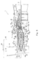
- Fig. 1 shows a gas turbine engine (hereinafter simply referred to as gas turbine) according to Embodiment 1 of the present invention.
- a gas turbine 1 is configured such that a compressor 3 compresses air IA introduced from outside and guides the compressed air to a combustor 5, a fuel F is injected to the interior of the combustor 5 and combusted therein, and the resulting high-temperature and high-pressure combustion gas G drives a turbine 7.
- a compressor side of the gas turbine 1 in a center axis direction will be referred to as "front side” and a turbine side of the gas turbine 1 in the center axis direction is referred to as "rear side.”
- the compressor 3 is of an axial-flow type.
- the axial-flow compressor 3 includes a compressor rotor 11 constituting the front portion of a rotary section of the gas turbine 1.
- the compressor rotor 11 is divided into two sections, i.e., front and rear sections.
- the compressor rotor 11 includes a compressor rotor body 11A which is the front section, and a compressor rotor extending section 11B coupled to the rear end portion of the compressor rotor body 11A by means of a bolt (not shown) such that the compressor rotor extending section 11B is unable to rotate relative to the compressor rotor body 11A.
- a number of rotor vanes 13 are arranged on the outer peripheral surface of the compressor rotor body 11A.
- the air IA suctioned from an air-intake tube 19 through a space between the housing 15 and an inner cowling 20 located radially inward relative to the housing 15 is compressed.
- the compressed air CA is supplied to the combustor 5 via a diffuser 21 disposed downstream of the compressor 3.
- the compressor rotor 11 includes a plurality of compressor rotor segments 23 stacked together and coupled together in a center axis direction of the compressor rotor 11.
- Each compressor rotor segment 23 includes a disc 25 forming a radially inward portion.
- the plurality of rotor vanes 13 are implanted on the outer peripheral portion of the disc 25 at equal intervals in a circumferential direction.
- the compressor rotor 11 has a hollow shape.
- Each compressor rotor segment 23 has a through-hole 27 penetrating the center portion of the disc 25 in the center axis direction.
- the compressor rotor 11 entirely has a hollow portion 29 defined by the through-holes 27.
- a plurality of combustors 5 are arranged at equal intervals in the circumferential direction of the gas turbine 1.
- the compressed air CA supplied from the compressor 3 is mixed with the fuel F injected to the interior of the combustor 5 and combusted therein, and the resulting high-temperature and high-pressure combustion gas G flows into the turbine 7 through a turbine nozzle (first stator vane) 23.
- the turbine 7 includes a turbine rotor 33 constituting the rear portion of the rotary section of the gas turbine 1 and a turbine casing 35 covering the turbine rotor 33.
- a plurality of turbine stator vanes 37 are attached on the inner peripheral portion of the turbine casing 35 at predetermined intervals.
- the turbine rotor 33 is provided with a plurality of turbine rotor vanes 39 positioned downstream of the turbine stator vanes 37, respectively.
- the two rotors 11, 33 are entirely rotatably supported on the housing 15 via a front bearing 43, a center bearing 45, and a rear bearing 47.
- a pipe unit 51 is inserted into the hollow portion 29 of the compressor rotor 11 in a direction of a rotor center axis C.
- the pipe unit 51 includes a plurality of steel-made pipe members 53 having an outer diameter smaller than a hole diameter of the through-hole 27 and a plurality of steel-made flanges 55 provided on the outer peripheries of the pipe members 53.
- the pipe unit 51 is inserted into the hollow portion 29 of the compressor rotor 11 from forward.
- a front end portion 51a of the pipe unit 51 is fastened to the compressor rotor 11 via a disc-shaped support member 56 positioned at a front end portion 11a of the compressor rotor 11.
- the plurality of pipe members 53 are arranged in series along the rotor center axis C. Adjacent pipe members 53 are coupled together by a flange 55. More specifically, the flange 55 includes an inner peripheral wall 55a fitted to the outer peripheral portions of the end portions of the pipe members 53 facing each other, an outer peripheral wall 55b fitted to the inner peripheral surface 11b of the compressor rotor 11, and a coupling wall 55c coupling the peripheral walls 55a, 55b together.
- the two pipe members 53 are welded to the inner peripheral wall 53a and thereby joined together.
- a slight gap S is present between the outer peripheral wall 55b of the flange 55 and the inner peripheral surface 11b of the compressor rotor 11, a slight gap S is present to allow the flange 55 to be inserted into the through-hole 27.
- a plurality of (six in the present embodiment) flanges 55 are provided at axially different locations, only one flange 55 may be provided.
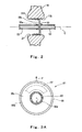
- the pipe unit 51 is configured to have an eccentric weight distribution within an axial transverse section perpendicular to the rotor center axis C (hereinafter referred to as "weight distribution"), the weight distribution being eccentric with respect to the rotor center axis C.
- weight distribution within an axial transverse section perpendicular to the rotor center axis C
- the weight distribution of the flange 55 is made eccentric with respect to the rotor center axis C.
- a weight 57 is embedded in a portion of the coupling wall 55c of the flange 55 to allow the weight distribution to be eccentric.
- a portion of the coupling wall 55c of the flange 55 may be cut out to provide an axial through-hole 59.
- a thinned-wall portion 61 may be provided by thinning a portion of the coupling wall 55c of the flange 55.
- the weight distribution of the pipe unit 51 may be made eccentric with a small amount.
- the outer peripheral wall 55b of the flange 55 may be pressed against the inner peripheral surface 11b of the compressor rotor 11 by rotating the flange 55 integrally with the compressor rotor 11, in a range of a rotational speed which is no less than 60% of a rated rotational speed of the compressor rotor 11.
- the pipe unit 51 is configured such that the flange 55 is provided on the outer periphery of the pipe member 53 as described above, it becomes easy to mount the pipe unit 51 to the rotor and position the pipe unit 51 with respect to the rotor. In addition, by making the weight distribution of the flange 55 eccentric, it becomes easy to manufacture the pipe unit 51 having an eccentric weight distribution.
- the structure of the pipe unit 51 is not limited to the example of Fig. 1 including the pipe member 53 and the flange 55, so long as the pipe unit 51 has an inner space extending axially and its weight distribution is eccentric.
- the flange 55 may be omitted, and the pipe unit 51 may consist of the pipe member 53.
- the thickness of the inner peripheral wall 53a may be set asymmetric with respect to the rotor center axis C.
- the weight distribution of the pipe unit 51 can be made eccentric.
- the pipe unit 51 forms a passage (cooling medium passage) RP of a cooling medium RA for cooling the interior of the gas turbine 1.
- the pipe unit 51 extends from the front end portion 11a of the compressor rotor 11 to the rear end portion 11c of the compressor rotor 11.
- the front end portion 51a of the pipe unit 51 penetrates a support member 56 and communicates with a compressed air extraction passage 63.
- the rear end portion 51b of the pipe unit 51 opens toward the turbine rotor 33.
- the compressed air CA extracted from the compressor 3 via the compressed air extraction passage 63 is guided to a region in the vicinity of the turbine rotor 33 through the cooling medium passage RP inside of the pipe member 53 and cools the turbine rotor 33 as the cooling medium RA.
- the interior of the gas turbine can be cooled by utilizing the hollow portion 29 which is the inner space of the compressor rotor 11. Therefore, characteristics such as efficiency and life of the engine can be improved while suppressing an increase in a dimension of the gas turbine 1.
- the compressed air CA extracted from the compressor 3 is used as the cooling medium RA, the cooling of the interior of the gas turbine 1 can be performed efficiently without introducing air for cooling.
- the weight distribution of the pipe unit 51 is eccentric, the flange 55 of the pipe unit 51 is pressed against the inner peripheral surface 11b of the compressor rotor 11 by a centrifugal force in an eccentric direction P as shown in Fig. 3A , according to the rotation of the pipe unit 51 together with the compressor rotor 11. As a result, the pipe unit 51 is stably supported on the compressor rotor 11 and will not whirl.
- Fig. 5 is a longitudinal sectional view showing the gas turbine engine 1 according to Embodiment 2 of the present invention.
- the pipe unit 51 is formed as a passage SP of seal air for sealing the center bearing 45, rather than the cooling medium passage of Embodiment 1.
- Embodiment 2 is identical to Embodiment 1 except for the following.
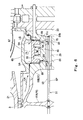
- Fig. 6 is a longitudinal sectional view showing a region surrounding the center bearing 45, in an enlarged manner.
- a bearing housing 65 which is a first bearing case is coupled to the downstream end portion of the inner peripheral wall of the diffuser 21, by means of a bolt which is not shown.
- the bearing housing 65 covers an axial center portion of the compressor rotor extending section 11B at which the center bearing 45 is located.
- a bearing box 67 which is a second bearing case is provided inward relative to the bearing housing 65.
- a bearing chamber 60 is formed to accommodate the center bearing 45, radially inward relative to the bearing box 67.
- Air seal mechanisms 69 are provided at both sides axially outward relative to the bearing chamber 60.
- the air seal mechanism 69 is a seal mechanism for preventing high-temperature air LA which has leaked from the compressor 3 or high-temperature gas LG which has leaked from the combustor 5 from entering the bearing chamber 60 through a vent chamber 71 communicating with outside of the engine.
- the vent chamber 71 is a space between the bearing housing 65 and the bearing box 67.
- the compressor rotor extending section 11B is provided with through-holes extending from the hollow portion 29 to the air seal mechanisms 69, as seal air introduction passages 79 for providing communication between the center portion 29 and the air seal mechanisms 69.
- a rear end portion 51b of the pipe member 53 of the pipe unit 51 is closed.
- Air output holes 81 which are radial through-holes are provided on the peripheral wall of a portion of the compressor rotor extending section 11B which is inserted into the hollow portion 29.
- the interior of the gas turbine can be sealed by utilizing the hollow portion 29 which is the inner space of the compressor rotor 11. Therefore, characteristics such as efficiency and life of the engine can be improved while suppressing an increase in a dimension of the gas turbine 1. Since the compressed air CA extracted from the compressor 3 is used as the seal air SA, the sealing of the interior of the gas turbine 1 can be performed efficiently without introducing air for cooling or sealing.
- Fig. 7 is a cross-sectional view showing a gas turbine according to Embodiment 3 of the present invention.
- a measurement cable 85 is extended to inside of the pipe unit 51.
- Embodiment 3 is identical to Embodiment 1 except for the following.
- the pipe unit 51 is extended from the front end portion 11a of the compressor rotor 11 to the rear end portion 11c of the compressor rotor 11.
- the cable 85 is used to take out a measurement signal of a temperature of the turbine rotor 33 attached with rotor vanes of the turbine 7. Specifically, one end of the cable 85 is connected to a temperature sensor 87 attached on the turbine rotor 33, while the other end of the cable 85 is connected to a telemeter transmitter 89.
- the telemeter transmitter 89 is a device for transmitting the measurement signal by radio.
- Fig. 8 is an enlarged cross-sectional view showing a region surrounding the front end portion 11a of the compressor rotor 11 of Fig. 7 .
- the telemeter transmitter 89 is mounted to an annular support 91 fastened to the front end portion 11a of the compressor rotor 11 together with the support member 56, by means of a bolt 90, and is rotatable with the compressor rotor 11.
- the telemeter transmitter 89 has a transmission antenna 93 on its an inner peripheral portion.
- a receiving antenna 95 of a telemeter receiver (not shown) is supported on an inner cowling 20 which is a non-rotating member of the compressor 3 and faces the transmission antenna 93 in a radial direction.
- the measurement signal of the temperature sensor 87 of Fig. 7 is transmitted to the telemeter receiver installed outside via the cable 85, the transmission antenna 93 and the receiving antenna 95.
- the sensor connected to one end of the cable 85 is the temperature sensor 87.
- a measurement element connected to the cable 85 is not limited to the temperature sensor 87, but may be various measurement devices such as a strain sensor or a rotation sensor.
- the cable 85 is not limited to the measurement cable 85 described in the present embodiment, but may be cables for various purposes as necessary such as control signal transmission or electric power transmission for a device installed inside. In this configuration, higher functionality and higher performance of the gas turbine engine can be achieved, by efficiently utilizing the hollow portion 29 which is the inner space of the compressor rotor 11.
- the cable 85 inside the pipe unit 51 is not fastened to the interior of the pipe unit 51, it will whirl inside the pipe member 53 of the pipe unit 51, when it is rotating together with the compressor rotor 11 and the pipe unit 51.
- the weight distribution of the pipe unit 51 within the axial transverse section is eccentric, it becomes possible to prevent the pipe unit 51 from whirling in the hollow portion 29 of the pipe unit 51 by the influence of the whirl of the cable 85.
- the pipe unit 51 provided in the inner space of the rotor is utilized as a cable layout member, higher performance and higher functionality of the gas turbine 1 can be achieved, while suppressing an increase in the dimension of the overall gas turbine 1.
- the pip unit 51 is provided in the hollow portion 29 of the compressor rotor 11, it may be provided in the turbine rotor 33 instead of or in addition to the compressor rotor 11.
- the present invention is effective in achievement of higher performance and higher functionality of a gas turbine engine while suppressing an increase in a dimension of an overall gas turbine engine.
Landscapes
- Engineering & Computer Science (AREA)
- Mechanical Engineering (AREA)
- General Engineering & Computer Science (AREA)
- Turbine Rotor Nozzle Sealing (AREA)
Abstract
Description
- The present invention relates to a gas turbine engine including a pipe for use as a passage of a cooling medium, a cable layout member, or the like.
- In a gas turbine engine which takes out driving power by high-temperature combustion gas generated by combusting air compressed in a compressor, it is necessary to cool the interior of the engine, to improve performance and life of the engine. As a structure for cooling the interior of the gas turbine engine, it is proposed that a pipe is extended axially inside of a rotor constituting a turbine and is used as a cooling medium passage (e.g., Patent Literature 1).
- Patent Literature 1: Japanese Laid-Open Patent Application Publication No.
Hei. 11-257012 - In general, a compressor rotor or a turbine rotor in a gas turbine engine is assembled in such a manner that a plurality of rotor segments are coupled together in a center axis direction thereof. Therefore, it is difficult to form a pipe in an inner space of the rotor integrally with the rotor and fasten the pipe to the rotor by means of a fastener member such as a bolt, in terms of productivity. Therefore, it is necessary to insert the pipe into a through-hole provided inside of the rotor before or after assembling of the rotor. In this case, however, a small gap is unavoidably formed between the pipe and a peripheral wall of the through-hole. As a result, when the rotor is rotating at a high speed, the pipe whirls inside the through-hole, which causes a problem that efficiency and life of the gas turbine engine are reduced.
- The present invention is directed to solving the above mentioned problem, and an object of the present invention is to provide a gas turbine engine which can prevent whirl of a pipe provided in an inner space of a rotor to transport a cooling medium or lay out cables, for example, and thus can achieve higher performance and reliability.
- To achieve the above describe object, a gas turbine engine of the present invention comprises a hollow rotor including a plurality of rotor segments coupled together in a direction of its center axis and defining at least one of a compressor and a turbine; and a pipe unit inserted into an inner space of the rotor in the center axis direction, wherein a weight distribution of the pipe unit within an axial transverse section is eccentric with respect to the center axis of the rotor.
- In accordance with this configuration, since the pipe unit is provided in the inner space of the hollow rotor and is utilized as a cooling medium passage or a cable layout member, higher performance and higher functionality of the gas turbine engine can be achieved, while suppressing an increase in a dimension of the overall gas turbine engine. Since the weight distribution of the pipe unit is made eccentric, the pipe unit is displaced only in a specified direction with respect to the rotor, during rotation of the rotor. This makes it possible to suppress the pipe unit from whirling inside of the rotor. Therefore, reliability of the gas turbine engine can be maintained.
- In the gas turbine engine of the present invention, preferably, the pipe unit includes a pipe member and a flange provided on an outer periphery of the pipe member and fitted to an inner peripheral surface of the rotor. In this case, preferably, a weight distribution of the flange within the axial transverse section is eccentric with respect to the center axis of the rotor. Since the flange is provided on the outer periphery of the pipe member, it becomes easy to mount the pipe unit to the rotor and position the pipe unit with respect to the rotor. Moreover, since the weight distribution of the flange within the axial transverse section is made eccentric, the pipe unit which is eccentric can be manufactured easily.
- In the gas turbine engine of the present invention, the pipe unit may constitute a passage of a cooling medium for cooling an interior of the gas turbine engine or a passage of seal air for sealing a bearing supporting the rotor such that the rotor is rotatable. In accordance with this configuration, by utilizing the inner space of the rotor, the interior of the engine can be cooled or sealed. Therefore, characteristics such as efficiency and life of the engine can be improved, while suppressing an increase in a dimension of the gas turbine engine.
- When in the gas turbine engine of the present invention, the pipe unit constitutes the cooling medium passage, or the seal air passage, the rotor may be a compressor rotor, and the cooling medium or the seal air may be compressed air extracted from the compressor. In accordance with this configuration, the cooling or sealing of the interior of the gas turbine engine can be performed efficiently by utilizing the compressed air of the compressor, without introducing air for cooling or sealing.
- In the gas turbine engine of the present invention, a cable may be extended to inside of the pipe unit. In accordance with this configuration, by extending, for example, a wire used to transmit a measurement signal of a temperature sensor, a strain sensor, etc., to inside of the pipe unit, as the cable, higher functionality of the gas turbine engine can be achieved by utilizing the inner space of the rotor.
- As described above, in accordance with the gas turbine engine of the present invention, it is possible to prevent whirl of a pipe mounted to the inner peripheral surface of a rotor to allow a cooling medium to be transported therethrough or a cable to be inserted thereinto, and as a result, performance and reliability of the gas turbine engine can be improved.
-
- [
Fig. 1] Fig. 1 is a side view showing a gas turbine engine according to Embodiment 1 of the present invention, a part of which is cut away. - [
Fig. 2] Fig. 2 is a longitudinal sectional view showing major components of the gas turbine engine ofFig. 1 . - [
Fig. 3A] Fig. 3A is a front view showing an example of a pipe unit for use in the gas turbine engine ofFig. 1 . - [
Fig. 3B] Fig. 3B is a front view showing an example of the pipe unit for use in the gas turbine engine ofFig. 1 . - [
Fig. 3C] Fig. 3C is a longitudinal sectional view showing an example of the pipe unit for use in the gas turbine engine ofFig. 1 . - [
Fig. 4] Fig. 4 is a cross-sectional view showing a modified example of the pipe unit for use in the gas turbine engine ofFig. 1 . - [
Fig. 5] Fig. 5 is a cross-sectional view showing a gas turbine engine according to Embodiment 2 of the present invention, a part of which is cut away. - [
Fig. 6] Fig. 6 is a longitudinal sectional view showing an enlarged part ofFig. 4 . - [
Fig. 7] Fig. 7 is a cross-sectional view showing a gas turbine engine according toEmbodiment 3 of the present invention, a part of which is cut away. - [
Fig. 8] Fig. 8 is a longitudinal sectional view showing an enlarged part ofFig. 7 . - Hereinafter, an embodiment of the present invention will be described with reference to the drawings.
-
Fig. 1 shows a gas turbine engine (hereinafter simply referred to as gas turbine) according to Embodiment 1 of the present invention. Referring toFig. 1 , a gas turbine 1 is configured such that acompressor 3 compresses air IA introduced from outside and guides the compressed air to acombustor 5, a fuel F is injected to the interior of thecombustor 5 and combusted therein, and the resulting high-temperature and high-pressure combustion gas G drives aturbine 7. In description below, in some cases, a compressor side of the gas turbine 1 in a center axis direction will be referred to as "front side" and a turbine side of the gas turbine 1 in the center axis direction is referred to as "rear side." - In the present embodiment, the
compressor 3 is of an axial-flow type. The axial-flow compressor 3 includes acompressor rotor 11 constituting the front portion of a rotary section of the gas turbine 1. Thecompressor rotor 11 is divided into two sections, i.e., front and rear sections. Specifically, thecompressor rotor 11 includes acompressor rotor body 11A which is the front section, and a compressorrotor extending section 11B coupled to the rear end portion of thecompressor rotor body 11A by means of a bolt (not shown) such that the compressorrotor extending section 11B is unable to rotate relative to thecompressor rotor body 11A. A number ofrotor vanes 13 are arranged on the outer peripheral surface of thecompressor rotor body 11A. By combining therotor vanes 13 and a number ofstator vanes 17 arranged on the inner peripheral surface of ahousing 15, the air IA suctioned from an air-intake tube 19 through a space between thehousing 15 and aninner cowling 20 located radially inward relative to thehousing 15 is compressed. The compressed air CA is supplied to thecombustor 5 via adiffuser 21 disposed downstream of thecompressor 3. - The
compressor rotor 11 includes a plurality ofcompressor rotor segments 23 stacked together and coupled together in a center axis direction of thecompressor rotor 11. Eachcompressor rotor segment 23 includes adisc 25 forming a radially inward portion. The plurality ofrotor vanes 13 are implanted on the outer peripheral portion of thedisc 25 at equal intervals in a circumferential direction. Thecompressor rotor 11 has a hollow shape. Eachcompressor rotor segment 23 has a through-hole 27 penetrating the center portion of thedisc 25 in the center axis direction. Thus, thecompressor rotor 11 entirely has ahollow portion 29 defined by the through-holes 27. - A plurality of
combustors 5 are arranged at equal intervals in the circumferential direction of the gas turbine 1. In thecombustor 5, the compressed air CA supplied from thecompressor 3 is mixed with the fuel F injected to the interior of thecombustor 5 and combusted therein, and the resulting high-temperature and high-pressure combustion gas G flows into theturbine 7 through a turbine nozzle (first stator vane) 23. - The
turbine 7 includes aturbine rotor 33 constituting the rear portion of the rotary section of the gas turbine 1 and aturbine casing 35 covering theturbine rotor 33. A plurality ofturbine stator vanes 37 are attached on the inner peripheral portion of theturbine casing 35 at predetermined intervals. Theturbine rotor 33 is provided with a plurality ofturbine rotor vanes 39 positioned downstream of theturbine stator vanes 37, respectively. The tworotors housing 15 via afront bearing 43, a center bearing 45, and arear bearing 47. - A
pipe unit 51 is inserted into thehollow portion 29 of thecompressor rotor 11 in a direction of a rotor center axis C. Specifically, thepipe unit 51 includes a plurality of steel-madepipe members 53 having an outer diameter smaller than a hole diameter of the through-hole 27 and a plurality of steel-madeflanges 55 provided on the outer peripheries of thepipe members 53. Thepipe unit 51 is inserted into thehollow portion 29 of thecompressor rotor 11 from forward. Afront end portion 51a of thepipe unit 51 is fastened to thecompressor rotor 11 via a disc-shapedsupport member 56 positioned at afront end portion 11a of thecompressor rotor 11. - As shown in
Fig. 2 , the plurality ofpipe members 53 are arranged in series along the rotor center axis C.Adjacent pipe members 53 are coupled together by aflange 55. More specifically, theflange 55 includes an innerperipheral wall 55a fitted to the outer peripheral portions of the end portions of thepipe members 53 facing each other, an outerperipheral wall 55b fitted to the innerperipheral surface 11b of thecompressor rotor 11, and acoupling wall 55c coupling theperipheral walls pipe members 53 are welded to the innerperipheral wall 53a and thereby joined together. Between the outerperipheral wall 55b of theflange 55 and the innerperipheral surface 11b of thecompressor rotor 11, a slight gap S is present to allow theflange 55 to be inserted into the through-hole 27. Although as shown inFig. 1 , a plurality of (six in the present embodiment)flanges 55 are provided at axially different locations, only oneflange 55 may be provided. - As shown in
Fig. 3 , thepipe unit 51 is configured to have an eccentric weight distribution within an axial transverse section perpendicular to the rotor center axis C (hereinafter referred to as "weight distribution"), the weight distribution being eccentric with respect to the rotor center axis C. As a structure for allowingpipe unit 51 to have the eccentric weight distribution, preferably, the weight distribution of theflange 55 is made eccentric with respect to the rotor center axis C. - Specifically, for example, as shown in
Fig. 3A , aweight 57 is embedded in a portion of thecoupling wall 55c of theflange 55 to allow the weight distribution to be eccentric. Or, as shown inFig. 3B , a portion of thecoupling wall 55c of theflange 55 may be cut out to provide an axial through-hole 59. Or, as shown inFig. 3C , a thinned-wall portion 61 may be provided by thinning a portion of thecoupling wall 55c of theflange 55. - The weight distribution of the
pipe unit 51 may be made eccentric with a small amount. For example, the outerperipheral wall 55b of theflange 55 may be pressed against the innerperipheral surface 11b of thecompressor rotor 11 by rotating theflange 55 integrally with thecompressor rotor 11, in a range of a rotational speed which is no less than 60% of a rated rotational speed of thecompressor rotor 11. - Since the
pipe unit 51 is configured such that theflange 55 is provided on the outer periphery of thepipe member 53 as described above, it becomes easy to mount thepipe unit 51 to the rotor and position thepipe unit 51 with respect to the rotor. In addition, by making the weight distribution of theflange 55 eccentric, it becomes easy to manufacture thepipe unit 51 having an eccentric weight distribution. - The structure of the
pipe unit 51 is not limited to the example ofFig. 1 including thepipe member 53 and theflange 55, so long as thepipe unit 51 has an inner space extending axially and its weight distribution is eccentric. For example, as shown in the cross-section ofFig. 4 , theflange 55 may be omitted, and thepipe unit 51 may consist of thepipe member 53. If thepipe unit 51 consists of thepipe member 53, for example, the thickness of the innerperipheral wall 53a may be set asymmetric with respect to the rotor center axis C. Thus, the weight distribution of thepipe unit 51 can be made eccentric. - In the present embodiment, as shown in
Fig. 1 , thepipe unit 51 forms a passage (cooling medium passage) RP of a cooling medium RA for cooling the interior of the gas turbine 1. Thepipe unit 51 extends from thefront end portion 11a of thecompressor rotor 11 to therear end portion 11c of thecompressor rotor 11. Thefront end portion 51a of thepipe unit 51 penetrates asupport member 56 and communicates with a compressedair extraction passage 63. Therear end portion 51b of thepipe unit 51 opens toward theturbine rotor 33. Therefore, the compressed air CA extracted from thecompressor 3 via the compressedair extraction passage 63 is guided to a region in the vicinity of theturbine rotor 33 through the cooling medium passage RP inside of thepipe member 53 and cools theturbine rotor 33 as the cooling medium RA. - In the above configuration, the interior of the gas turbine can be cooled by utilizing the
hollow portion 29 which is the inner space of thecompressor rotor 11. Therefore, characteristics such as efficiency and life of the engine can be improved while suppressing an increase in a dimension of the gas turbine 1. Since the compressed air CA extracted from thecompressor 3 is used as the cooling medium RA, the cooling of the interior of the gas turbine 1 can be performed efficiently without introducing air for cooling. Since the weight distribution of thepipe unit 51 is eccentric, theflange 55 of thepipe unit 51 is pressed against the innerperipheral surface 11b of thecompressor rotor 11 by a centrifugal force in an eccentric direction P as shown inFig. 3A , according to the rotation of thepipe unit 51 together with thecompressor rotor 11. As a result, thepipe unit 51 is stably supported on thecompressor rotor 11 and will not whirl. -
Fig. 5 is a longitudinal sectional view showing the gas turbine engine 1 according to Embodiment 2 of the present invention. In Embodiment 2, thepipe unit 51 is formed as a passage SP of seal air for sealing the center bearing 45, rather than the cooling medium passage of Embodiment 1. Embodiment 2 is identical to Embodiment 1 except for the following. -
Fig. 6 is a longitudinal sectional view showing a region surrounding the center bearing 45, in an enlarged manner. As shown inFig. 6 , a bearinghousing 65 which is a first bearing case is coupled to the downstream end portion of the inner peripheral wall of thediffuser 21, by means of a bolt which is not shown. The bearinghousing 65 covers an axial center portion of the compressorrotor extending section 11B at which the center bearing 45 is located. Abearing box 67 which is a second bearing case is provided inward relative to the bearinghousing 65. A bearingchamber 60 is formed to accommodate the center bearing 45, radially inward relative to thebearing box 67.Air seal mechanisms 69 are provided at both sides axially outward relative to the bearingchamber 60. - The
air seal mechanism 69 is a seal mechanism for preventing high-temperature air LA which has leaked from thecompressor 3 or high-temperature gas LG which has leaked from thecombustor 5 from entering the bearingchamber 60 through avent chamber 71 communicating with outside of the engine. Thevent chamber 71 is a space between the bearinghousing 65 and thebearing box 67. - The compressor
rotor extending section 11B is provided with through-holes extending from thehollow portion 29 to theair seal mechanisms 69, as sealair introduction passages 79 for providing communication between thecenter portion 29 and theair seal mechanisms 69. Arear end portion 51b of thepipe member 53 of thepipe unit 51 is closed. Air output holes 81 which are radial through-holes are provided on the peripheral wall of a portion of the compressorrotor extending section 11B which is inserted into thehollow portion 29. - The compressed air CA which has been extracted from the
compressor 3 through the compressedair extraction passage 63 ofFig. 5 , passes through the seal air passage SP, and then is supplied as seal air SA to theair seal mechanisms 69 via the air output holes 81 and the sealair introduction passages 79 ofFig. 6 . A portion of the seal air SA supplied to theair seal mechanisms 69 flows out to thevent chamber 71, and prevents the high-temperature air from flowing into the bearingchamber 60. - In accordance with the gas turbine 1 of Embodiment 2, the interior of the gas turbine can be sealed by utilizing the
hollow portion 29 which is the inner space of thecompressor rotor 11. Therefore, characteristics such as efficiency and life of the engine can be improved while suppressing an increase in a dimension of the gas turbine 1. Since the compressed air CA extracted from thecompressor 3 is used as the seal air SA, the sealing of the interior of the gas turbine 1 can be performed efficiently without introducing air for cooling or sealing. -
Fig. 7 is a cross-sectional view showing a gas turbine according toEmbodiment 3 of the present invention. InEmbodiment 3, ameasurement cable 85 is extended to inside of thepipe unit 51.Embodiment 3 is identical to Embodiment 1 except for the following. - In the present embodiment, the
pipe unit 51 is extended from thefront end portion 11a of thecompressor rotor 11 to therear end portion 11c of thecompressor rotor 11. Thecable 85 is used to take out a measurement signal of a temperature of theturbine rotor 33 attached with rotor vanes of theturbine 7. Specifically, one end of thecable 85 is connected to atemperature sensor 87 attached on theturbine rotor 33, while the other end of thecable 85 is connected to atelemeter transmitter 89. - The
telemeter transmitter 89 is a device for transmitting the measurement signal by radio.Fig. 8 is an enlarged cross-sectional view showing a region surrounding thefront end portion 11a of thecompressor rotor 11 ofFig. 7 . As shown inFig. 8 , thetelemeter transmitter 89 is mounted to anannular support 91 fastened to thefront end portion 11a of thecompressor rotor 11 together with thesupport member 56, by means of abolt 90, and is rotatable with thecompressor rotor 11. Thetelemeter transmitter 89 has atransmission antenna 93 on its an inner peripheral portion. Radially inward relative to thetransmission antenna 93 of thetelemeter transmitter 89, a receivingantenna 95 of a telemeter receiver (not shown) is supported on aninner cowling 20 which is a non-rotating member of thecompressor 3 and faces thetransmission antenna 93 in a radial direction. The measurement signal of thetemperature sensor 87 ofFig. 7 is transmitted to the telemeter receiver installed outside via thecable 85, thetransmission antenna 93 and the receivingantenna 95. - In the present embodiment, description has been given of an example in which the sensor connected to one end of the
cable 85 is thetemperature sensor 87. A measurement element connected to thecable 85 is not limited to thetemperature sensor 87, but may be various measurement devices such as a strain sensor or a rotation sensor. Furthermore, thecable 85 is not limited to themeasurement cable 85 described in the present embodiment, but may be cables for various purposes as necessary such as control signal transmission or electric power transmission for a device installed inside. In this configuration, higher functionality and higher performance of the gas turbine engine can be achieved, by efficiently utilizing thehollow portion 29 which is the inner space of thecompressor rotor 11. - Since the
cable 85 inside thepipe unit 51 is not fastened to the interior of thepipe unit 51, it will whirl inside thepipe member 53 of thepipe unit 51, when it is rotating together with thecompressor rotor 11 and thepipe unit 51. However, since the weight distribution of thepipe unit 51 within the axial transverse section is eccentric, it becomes possible to prevent thepipe unit 51 from whirling in thehollow portion 29 of thepipe unit 51 by the influence of the whirl of thecable 85. - As described above, since the
pipe unit 51 provided in the inner space of the rotor is utilized as a cable layout member, higher performance and higher functionality of the gas turbine 1 can be achieved, while suppressing an increase in the dimension of the overall gas turbine 1. - Although in the above embodiments, the
pip unit 51 is provided in thehollow portion 29 of thecompressor rotor 11, it may be provided in theturbine rotor 33 instead of or in addition to thecompressor rotor 11. - Although description has been given of preferred embodiments of the present invention with reference to the drawings, the present invention can be added, changed or deleted in various ways within a scope of the present invention. Such addition, change and deletion can be included in the scope of the present invention.
- The present invention is effective in achievement of higher performance and higher functionality of a gas turbine engine while suppressing an increase in a dimension of an overall gas turbine engine.
-
- 1 gas turbine engine
- 2 compressor
- 5 combustor
- 7 turbine
- 11 compressor rotor
- 23 rotor segments
- 29 hollow portion (inner space of rotor)
- 51 pipe unit
- 53 pipe member
- 55 flange
- 85 cable
- SP seal air passage
- RP cooling medium passage
- RA cooling air
- SA seal air
Claims (7)
- A gas turbine engine comprising:a hollow rotor including a plurality of rotor segments coupled together in a direction of its center axis and defining at least one of a compressor and a turbine; anda pipe unit inserted into an inner space of the rotor in the center axis direction,wherein a weight distribution of the pipe unit within an axial transverse section is eccentric with respect to the center axis of the rotor.
- The gas turbine engine according to Claim 1,
wherein the pipe unit includes a pipe member and a flange provided on an outer periphery of the pipe member and fitted to an inner peripheral surface of the rotor. - The gas turbine engine according to Claim 2,
wherein a weight distribution of the flange within the axial transverse section is eccentric with respect to the center axis of the rotor. - The gas turbine engine according to any one of Claims 1 to 3,
wherein the pipe unit constitutes a passage of a cooling medium for cooling an interior of the gas turbine engine. - The gas turbine engine according to any one of Claims 1 to 3,
wherein the pipe unit constitutes a passage of seal air for sealing a bearing supporting the rotor such that the rotor is rotatable. - The gas turbine engine according to Claim 4 or 5,
wherein the rotor is a compressor rotor, and the cooling medium or the seal air is compressed air extracted from the compressor. - The gas turbine engine according to any one of Claims 1 to 3,
wherein a cable is extended to inside of the pipe unit.
Applications Claiming Priority (2)
| Application Number | Priority Date | Filing Date | Title |
|---|---|---|---|
| JP2010044426A JP4872006B2 (en) | 2010-03-01 | 2010-03-01 | Gas turbine engine |
| PCT/JP2011/000945 WO2011108216A1 (en) | 2010-03-01 | 2011-02-21 | Gas turbine engine |
Publications (2)
| Publication Number | Publication Date |
|---|---|
| EP2543851A1 true EP2543851A1 (en) | 2013-01-09 |
| EP2543851A4 EP2543851A4 (en) | 2013-11-06 |
Family
ID=44541886
Family Applications (1)
| Application Number | Title | Priority Date | Filing Date |
|---|---|---|---|
| EP11750330.0A Withdrawn EP2543851A4 (en) | 2010-03-01 | 2011-02-21 | GAS TURBINE ENGINE |
Country Status (5)
| Country | Link |
|---|---|
| US (1) | US20130034451A1 (en) |
| EP (1) | EP2543851A4 (en) |
| JP (1) | JP4872006B2 (en) |
| CA (1) | CA2791191C (en) |
| WO (1) | WO2011108216A1 (en) |
Cited By (4)
| Publication number | Priority date | Publication date | Assignee | Title |
|---|---|---|---|---|
| EP3105438A4 (en) * | 2014-02-13 | 2017-10-04 | United Technologies Corporation | Nacelle ventilation manifold |
| WO2017200644A1 (en) * | 2016-05-17 | 2017-11-23 | General Electric Company | Gas compressor and method of cooling a rotatable member |
| GB2574107A (en) * | 2018-03-30 | 2019-11-27 | Safran Aircraft Engines | Assembly for a turbine engine |
| US11879411B2 (en) | 2022-04-07 | 2024-01-23 | General Electric Company | System and method for mitigating bowed rotor in a gas turbine engine |
Family Cites Families (9)
| Publication number | Priority date | Publication date | Assignee | Title |
|---|---|---|---|---|
| US4571935A (en) * | 1978-10-26 | 1986-02-25 | Rice Ivan G | Process for steam cooling a power turbine |
| FR2499652A1 (en) * | 1981-02-11 | 1982-08-13 | Snecma | TURBOMACHINE ROTOR BALANCE CORRECTION DEVICE |
| JP3621523B2 (en) * | 1996-09-25 | 2005-02-16 | 株式会社東芝 | Gas turbine rotor blade cooling system |
| JP3334071B2 (en) * | 1997-05-16 | 2002-10-15 | 株式会社日立製作所 | Compressor rotor |
| DE19757945B4 (en) * | 1997-12-27 | 2006-11-30 | Alstom | Rotor for thermal turbomachinery |
| JP3285816B2 (en) * | 1998-03-16 | 2002-05-27 | 三菱重工業株式会社 | Gas turbine cooling medium transfer pipe |
| US6568091B1 (en) * | 2000-02-23 | 2003-05-27 | General Electric Company | Rotor component displacement measurement system |
| JP2003206701A (en) * | 2002-01-11 | 2003-07-25 | Mitsubishi Heavy Ind Ltd | Gas turbine turbine rotor and gas turbine |
| JP4113146B2 (en) * | 2004-03-17 | 2008-07-09 | 株式会社日立製作所 | Gas turbine and method for preventing detachment of heat shield tube |
-
2010
- 2010-03-01 JP JP2010044426A patent/JP4872006B2/en not_active Expired - Fee Related
-
2011
- 2011-02-21 WO PCT/JP2011/000945 patent/WO2011108216A1/en not_active Ceased
- 2011-02-21 CA CA2791191A patent/CA2791191C/en not_active Expired - Fee Related
- 2011-02-21 US US13/582,394 patent/US20130034451A1/en not_active Abandoned
- 2011-02-21 EP EP11750330.0A patent/EP2543851A4/en not_active Withdrawn
Cited By (8)
| Publication number | Priority date | Publication date | Assignee | Title |
|---|---|---|---|---|
| EP3105438A4 (en) * | 2014-02-13 | 2017-10-04 | United Technologies Corporation | Nacelle ventilation manifold |
| US10443429B2 (en) | 2014-02-13 | 2019-10-15 | United Technologies Corporation | Gas turbine nacelle ventilation manifold having a circumferential varying cross-sectional area |
| US10526910B2 (en) | 2014-02-13 | 2020-01-07 | United Technologies Corporation | Gas turbine engine nacelle ventilation manifold for cooling accessories |
| WO2017200644A1 (en) * | 2016-05-17 | 2017-11-23 | General Electric Company | Gas compressor and method of cooling a rotatable member |
| US10337405B2 (en) | 2016-05-17 | 2019-07-02 | General Electric Company | Method and system for bowed rotor start mitigation using rotor cooling |
| GB2574107A (en) * | 2018-03-30 | 2019-11-27 | Safran Aircraft Engines | Assembly for a turbine engine |
| GB2574107B (en) * | 2018-03-30 | 2022-09-21 | Safran Aircraft Engines | Assembly for a turbine engine |
| US11879411B2 (en) | 2022-04-07 | 2024-01-23 | General Electric Company | System and method for mitigating bowed rotor in a gas turbine engine |
Also Published As
| Publication number | Publication date |
|---|---|
| WO2011108216A1 (en) | 2011-09-09 |
| EP2543851A4 (en) | 2013-11-06 |
| JP2011179402A (en) | 2011-09-15 |
| JP4872006B2 (en) | 2012-02-08 |
| CA2791191A1 (en) | 2011-09-09 |
| CA2791191C (en) | 2014-08-05 |
| US20130034451A1 (en) | 2013-02-07 |
Similar Documents
| Publication | Publication Date | Title |
|---|---|---|
| US8899945B2 (en) | Centrifugal compressor unit | |
| US7521815B2 (en) | Micro power generating device | |
| RU2532479C2 (en) | Turbojet engine comprising improved facilities of regulation of flow rate of cooling air flow taken at outlet of high pressure compressor | |
| US8740550B2 (en) | Structure of exhaust section of gas turbine and gas turbine | |
| CN101688469B (en) | Supercharger with electric motor | |
| US8870544B2 (en) | Rotor cover plate retention method | |
| US9359958B2 (en) | Seal mechanism for use with turbine rotor | |
| CA2791191C (en) | Gas turbine engine | |
| US9771968B2 (en) | Turbine engine drive shaft device | |
| US9062557B2 (en) | Flow discourager integrated turbine inter-stage U-ring | |
| CN103306994B (en) | Centrifugal compressed device and assembling method thereof | |
| WO2019159744A1 (en) | Turbine | |
| KR20110021933A (en) | Cooling air supply structure of gas turbine and gas turbine | |
| KR20140099443A (en) | Rotor assembly having a concentric arrangement of a turbine portion, a cooling channel and a reinforcement wall | |
| CN216872972U (en) | Magnetic suspension vapor compressor | |
| CN114483203B (en) | Technology for inner shrouds used to cool gas turbine blades | |
| WO2017069249A1 (en) | Gas turbine rotor, gas turbine, and gas turbine equipment | |
| JP6162956B2 (en) | Turbine and nozzle assembly method | |
| EP3456925B1 (en) | Structure for cooling turbine blades, corresponding turbine and gas turbine | |
| CN113339287B (en) | Turbo compressor | |
| WO2019182933A1 (en) | A system to provide reliable flow of low temperature cooling air to an antifriction bearing buried inside a rotating machine | |
| KR102676873B1 (en) | compressor | |
| JP5876753B2 (en) | Centrifugal compressor | |
| JP4291738B2 (en) | Twin-shaft gas turbine | |
| CN219062054U (en) | Compressor impeller back cavity sealing structure and compressor |
Legal Events
| Date | Code | Title | Description |
|---|---|---|---|
| PUAI | Public reference made under article 153(3) epc to a published international application that has entered the european phase |
Free format text: ORIGINAL CODE: 0009012 |
|
| 17P | Request for examination filed |
Effective date: 20120906 |
|
| AK | Designated contracting states |
Kind code of ref document: A1 Designated state(s): AL AT BE BG CH CY CZ DE DK EE ES FI FR GB GR HR HU IE IS IT LI LT LU LV MC MK MT NL NO PL PT RO RS SE SI SK SM TR |
|
| DAX | Request for extension of the european patent (deleted) | ||
| A4 | Supplementary search report drawn up and despatched |
Effective date: 20131008 |
|
| RIC1 | Information provided on ipc code assigned before grant |
Ipc: F01D 25/16 20060101ALI20131001BHEP Ipc: F01D 25/00 20060101ALI20131001BHEP Ipc: F01D 5/08 20060101ALI20131001BHEP Ipc: F01D 11/04 20060101ALI20131001BHEP Ipc: F02C 7/18 20060101AFI20131001BHEP Ipc: F01D 5/06 20060101ALI20131001BHEP |
|
| STAA | Information on the status of an ep patent application or granted ep patent |
Free format text: STATUS: THE APPLICATION IS DEEMED TO BE WITHDRAWN |
|
| 18D | Application deemed to be withdrawn |
Effective date: 20160901 |