EP2543596A2 - Distributed ice protection control system - Google Patents
Distributed ice protection control system Download PDFInfo
- Publication number
- EP2543596A2 EP2543596A2 EP12175134A EP12175134A EP2543596A2 EP 2543596 A2 EP2543596 A2 EP 2543596A2 EP 12175134 A EP12175134 A EP 12175134A EP 12175134 A EP12175134 A EP 12175134A EP 2543596 A2 EP2543596 A2 EP 2543596A2
- Authority
- EP
- European Patent Office
- Prior art keywords
- control module
- ice protection
- server
- control
- aircraft
- Prior art date
- Legal status (The legal status is an assumption and is not a legal conclusion. Google has not performed a legal analysis and makes no representation as to the accuracy of the status listed.)
- Granted
Links
Images




Classifications
-
- B—PERFORMING OPERATIONS; TRANSPORTING
- B64—AIRCRAFT; AVIATION; COSMONAUTICS
- B64D—EQUIPMENT FOR FITTING IN OR TO AIRCRAFT; FLIGHT SUITS; PARACHUTES; ARRANGEMENT OR MOUNTING OF POWER PLANTS OR PROPULSION TRANSMISSIONS IN AIRCRAFT
- B64D15/00—De-icing or preventing icing on exterior surfaces of aircraft
- B64D15/12—De-icing or preventing icing on exterior surfaces of aircraft by electric heating
-
- B—PERFORMING OPERATIONS; TRANSPORTING
- B64—AIRCRAFT; AVIATION; COSMONAUTICS
- B64D—EQUIPMENT FOR FITTING IN OR TO AIRCRAFT; FLIGHT SUITS; PARACHUTES; ARRANGEMENT OR MOUNTING OF POWER PLANTS OR PROPULSION TRANSMISSIONS IN AIRCRAFT
- B64D15/00—De-icing or preventing icing on exterior surfaces of aircraft
- B64D15/16—De-icing or preventing icing on exterior surfaces of aircraft by mechanical means, e.g. pulsating mats or shoes attached to, or built into, surface
- B64D15/166—De-icing or preventing icing on exterior surfaces of aircraft by mechanical means, e.g. pulsating mats or shoes attached to, or built into, surface using pneumatic boots
-
- B—PERFORMING OPERATIONS; TRANSPORTING
- B64—AIRCRAFT; AVIATION; COSMONAUTICS
- B64D—EQUIPMENT FOR FITTING IN OR TO AIRCRAFT; FLIGHT SUITS; PARACHUTES; ARRANGEMENT OR MOUNTING OF POWER PLANTS OR PROPULSION TRANSMISSIONS IN AIRCRAFT
- B64D15/00—De-icing or preventing icing on exterior surfaces of aircraft
- B64D15/20—Means for detecting icing or initiating de-icing
- B64D15/22—Automatic initiation by icing detector
Definitions
- the present application relates to an ice protection system for an aircraft.
- ice protection systems for aircraft are configured with customized controllers, each controller being specifically tailored to perform a unique task.
- Such a system is susceptible to single point failures which can cause large portions of the ice protection system to fail.
- a modification of the ice protection system typically requires a new customized controller when the modification affects functionality controlled by that specific controller.
- prior art ice protection systems are typically specific to a certain aircraft.
- an ice protection control system for an aircraft and a method of operating an ice protection control system, as defined by the appended claims.
- Figure 1 is a schematic block diagram of a distributed ice protection system, according to an embodiment of the present application.
- Figure 2 is a stylized isometric view of a server module from the distributed ice protection system, according to an embodiment of the present application
- FIG. 3 is a schematic view of a server module from the distributed ice protection system, according to an embodiment of the present application
- Figure 4 is a schematic view of a server module from the distributed ice protection system, according to an embodiment of the present application.
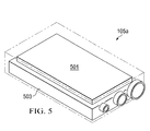
- Figure 5 is a stylized isometric view of a control module from the distributed ice protection system, according to an embodiment of the present application
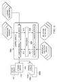
- FIG. 6 is a schematic view of a control module from the distributed ice protection system, according to an embodiment of the present application.
- Figure 7 is a schematic block diagram of an implementation of a distributed ice protection system, according to an embodiment of the present application.
- Figure 8 is a stylized perspective view of an aircraft having a distributed ice protection system, according to an embodiment of the present application.
- the present application includes a distributed ice protection system (D-IPS) 101.
- Distributed ice protection system 101 utilizes a distributed control system with a server/client communication protocol to prevent single point failures, reduce affected system loss when a failure occurs, improve required maintenance turn-around time, and provide a tailorable, interactive, integrated, cross platform solution for a variety of aircraft ice protection requirements.
- Distributed ice protection system 101 includes master servers and control modules that are compatible with a variety of aircraft platforms.
- distributed ice protection system 101 includes a generic control core 103.
- Generic control core 103 includes master server 111, standby server 113, and control modules, such as control modules 105a-105d.
- Control modules 105a-105d interface with individual anti-ice and de-ice hardware components, such as anti-ice components 107a-107d and de-ice components 109a and 109b.
- anti-ice components 107a-107d and de-ice components 109a and 109b are hardware implementations in the specific aircraft.
- Control modules 105a-105d are preferably located near the anti-ice or de-ice component for which it controls. It should be appreciated any plurality of master servers, standby servers, primary control modules, and standby control modules can be used in an implementation. Further, it should be appreciated that a specific implementation can employ any level of redundancy for specific servers and control modules.
- Control modules 105a-105d are generic modules that are configured for the aircraft via software for the specific function needed. Each module 105a-105d can swap places and be reconfigured through the master server 111 for their new location. Control modules 105a-105d are robust and configured to withstand high thermal and vibratory loading. Further, the electronics within each control module 105a-105d are preferably sealed off from the environment.
- Each control module 105a-105d can operate independently from other individual control modules 105a-105d by pulling and storing required data to/from a master server 111.
- Master server 111 is the server for distributed ice protection system 101, such that master server 111 provides data transfer and storage for control modules 105a-105d.
- a standby server 113 acts as a fully redundant backup for master server 111.
- Master server 111 can also interface with an aircraft multi-function display interface (MFD) 115 and a ground maintenance interface 117.
- Ground maintenance interface 117 may be a computer, such as a portable laptop, for example, which enables personnel to configure each control module 105a-105d.
- ground maintenance interface 117 may be used to load software and customize the functionality of each control module 105a-105d, via master server 111.
- ground maintenance interface 117 provides access to master server 111 in order to retrieve fault data, provide integrated on-board troubleshooting procedures and testing, and recommended maintenance requirements via a web-browser based interface that can be accessed through laptop computer capabilities.
- the software contains a set of core control tools with additional functionality tailored to specific platform needs.
- Multi-function display 115 is an interface for an aircraft operator, such as a pilot, co-pilot, or other aircraft occupant, for example. Multi-function display 115 can allow that the aircraft operator to check the status and make commands to control modules 105a-105d.
- control module 105b is configured as a redundant (standby) controller to control module 105a. In an instance of failure of control module 105a, control module 105b is configured automatically take over control of anti-ice components 107a and 107b, as discussed further herein. As illustrated in Figure 1 , components 107a and 107b are electrically coupled to both control module 105a and 105b. It should be fully appreciated that control modules 105c and 105d can also have redundant control modules.
- Server modules 111 and 113 are configured to provide data transfer and data storage for control modules 105a-105d. Server modules 111 and 113 are also configured as the interface to aircraft multi-function display interface (MFD) 115 and ground maintenance interface 117. Further, server modules 111 and 113 are the software load points and system configuration load points for all control modules 105a-105d. Control modules 105a-105d each operate independently by pulling/storing required data from/to server modules 111 and 113. Each primary control module is assigned to a region in an enclosure tailored to meet the specific needs in that region of the aircraft, the primary control module being used to control all anti-ice and de-ice zones in that region of the aircraft.
- MFD multi-function display interface
- each control module 105a-105d downloads environment data, such as outside air temperature and true airspeed from server 111.
- Each control module 105a-105d has software downloaded from server 111 so it can monitor, control, record, and communicate back to server 111.
- Each control module 105a-105d is fully functional once the operational software is downloaded from the server.
- each control module 105a-105d is configured to operate anti-ice and de-ice components without relying on operational commands from server 111.
- control modules 105a-105d do not require functional commands from server 111. Rather, server 111 acts at least as 1) an interface with the aircraft, 2) data storage and data collection point, 3) data analysis, historical trending, and system component diagnostics, and 4) maintenance interface. Server 111 also decides what information is communicated via aircraft multi-function display interface 115.
- Server module 111 can include a processor board 201, a memory storage 203, and a sensor connector 221 for an environmental interface 205, a communications connector 219, and a power connector 223 for power source 209.
- Memory storage 203 is preferably solid state.
- Server module 111 is configured as the central interface for distributed ice protection system 101.
- Environmental interface unit 205 is provided so server module 111 can interface with sensors, such as ice detectors 213, true airspeed (TAS) sensors 215, and outside air temperature (OAT) sensors 217.
- Server module 111 is configured as the storage point for all system data including environmental conditions, fault logs, data logs, a maintenance suite, configuration files, and software for control modules 105a-105d.
- Processor board 201 is configured to incorporate functional units, such as a data storage unit 211, a communications unit 207, an environmental interface unit 205, a processor unit 206, and a power distribution unit 208.
- Processor unit 206 can act as the central interface point between all the units and contain the main chipset for processing all data and functions of server module 111, as more particularly illustrated in Figure 4 .
- Data storage unit 211 can contain the buffers and interfaces to the solid state memory 203.
- Environmental interface unit 205 can contain the conditioning circuits and the analog to digital converter.
- Communications unit 207 can contain the transmitter, receiver, and buffer circuits for all communications.
- Power unit 209 can provide voltage regulation and power distribution for the circuitry and solid state memory.
- Processor unit 206 can consist of the required chipset to execute all necessary functions for the server capabilities.
- processor unit 206 can be capable of hosting a program created in the C programming language.
- Data storage unit 211 can contain sufficient random access memory requisite for memory usage and other memory program storage. Periodically, a record can be taken of memory parameters located in RAM and stored on the solid state memory during in-flight icing encounters to providing trending records and historical data.
- Environmental unit 205 can contain signal conditioning and analog to digital conversion circuits to interface with sensor inputs, such as ice detectors inputs, outside air temperature sensor inputs, and true airspeed sensor inputs. Once the data is conditioned and converted, the information can be passed to processor unit 206 for storage and use by system 101. Environmental unit 205 is also configured to read a health discrete from each sensor.
- sensor inputs such as ice detectors inputs, outside air temperature sensor inputs, and true airspeed sensor inputs.
- Communication unit 207 is configured as the interface between the aircraft communication bus and system 101. Communication unit 207 is configured to receive data from the mission computer and pass it up to processor unit 206. Communication unit 207 is also configured to act as a bus controller and server interface for all control modules 105a-105d within system 101. Data packets received from a control module, such as one of control modules 105a-105d, can be passed to processor unit 206 for processing and storage. Any information requests from any of control modules 105a-105d can be processed by processor unit 206 and the data returned to communication unit 207 across the bus.
- each server module can contain and process the same data; however, master server 111 is the primary processor/control interface unless a fault occurs in the system. Further, master server 111 and standby server 113 each maintain a health status of itself on its respective server. Master server 111 and standby server 113 monitor the state of the other; if a fault occurs in one of the modules, the other module will assume responsibility for the faulted portion of the unit. Each server module broadcasts a periodic health status message. If one of the server modules fails to broadcast the periodic health status message, the remaining server module will assume full responsibility for the system for the remainder of the power cycle. In an implementation of a plurality of master and standby servers, such as a quad server implementation, the redundant responsibilities can be selectively divided among the plurality of master and standby servers.
- the software for each server module 111 is responsible for data transfer between mission computer 225 and control system 101, server functionality for the client control system, current status of aircraft/environment, system parameters, data storage for control modules 105a-105d, maintenance information, environmental input processing, fault reporting/consolidation, maintenance interface processing, system software loading and configuring, data transfer to an independent multi-function display (such as MFD 115), and system theory of operation interface.
- the software for each server module 111 can contain core functionality generic to any aircraft platform and platform specific software configured to meet the specific unique attributes of the aircraft. Software containing core functions and platform specific functions are kept isolated from each other by utilizing object oriented attributes.
- each control module 105a-105d (for clarity, only control module 105a is illustrated) is a generic control brick configured to be utilized across the system platform for monitoring and controlling anti-ice and de-ice surfaces.
- Control module 105a can include a processor board 501 and a conditioning board 503.
- Control module 105a can be inserted into an implementation specific enclosure for the specific area on the platform with a relay bank designed for that implementation.
- Control module 105a is configured to monitor line currents for electro-thermal surfaces and resistive-thermal devices for controlling electro-thermal surfaces within a specified temperature band.
- Control module 105a can utilize a 28VDC output signal to control relays within the enclosure, or in specified cases, an external relay or actuator.
- control module 105a can include a processor unit 505, a discrete input unit 507, a discrete output unit 509, an analog input unit 511, and a communications unit 513.
- Processor unit 505 is configured to act as a central interface point between all the functional units and contain the main chipset for processing all data and functions of control module 105a, as illustrated in Figure 6 .
- Discrete input unit 507 is configured to process data from a discrete status signal, such as a wrap back line or present/not-present indication from an actuator.
- Analog input unit 511 is configured to contain the condition circuits and analog-to-digital converter for reading temperature sensors and current transformers in system 101.
- Communications unit 513 is configured to contain any required transmitter, receiver, and buffer circuitry with a 28VDC output to turn on/off relays or actuators in system 101.
- primary control module 105a acts as the default master controller while control module 105b is the backup controller.
- Each control module 105a and 105b contains and processes the same data; however, master control module 105a is the primary processor/control interface unless a fault occurs in system 101.
- Each module 105a and 105b maintains a health status of itself on the server module 111.
- Control modules 105a and 105b each monitor the health state of the other; if a fault occurs in one of control modules 105a and 105b, the other control module will assume responsibility for the faulted portion of the unit.
- Each control module 105a and 105b broadcasts a periodic health status message. If master control module 105a for a specific control area fails to broadcast the periodic health status message, standby control module 105b will assume full responsibility for the specified control area for the remainder of the power cycle.
- Each control module 105a-105d includes hardware and circuitry capable of meeting the functionality described herein for processing, communications, discrete input/output, and analog signal conditioning or conversion.
- Processor unit 505 can consist of the required chipset to execute all necessary functions for the server capabilities.
- processor unit 505 can be capable of hosting a program created in the C programming language.
- Processor unit 505 can contain sufficient random access memory requisite for memory usage and other memory program storage.
- a record can be taken of memory parameters located in RAM and uploaded to master server 111 and standby server 113 during in-flight icing encounters to providing trending records and historical data.
- Processor unit 505 is configured with bus controllers that interface with the discrete input unit 507, discrete output unit 509, analog input unit 511, and communications unit 513.
- Discrete input unit 507 and discrete output unit 509 are configured to monitor discrete inputs and commanding 28VDC discrete outputs.
- the outputs of the discrete output unit 509 are configured for driving solid state or mechanical relays, as well as 28 VDC actuators.
- Analog input unit 511 is configured with signal conditioning and analog to digital conversion circuits to interface with system analog inputs. Once the data is conditioned and converted, the information is passed to processor unit 505 for storage and use by system 101.
- Communications unit 513 is configured as the interface between the servers (such as servers 111 and 113) and control module 105a. Data packets are uploaded to servers 111 and 113 from control module 105b for processing and storage. Control module 105a downloads data for use within the control module 105a from server 111 and/or server 113, as needed. Servers 111 and 113 are capable of pushing data to the control modules as needed to ensure system health.
- each control module 105a-105d is preferably mostly common across platforms with the primary platform specific software being related to control, monitoring, and fault isolation requirements for the platform.
- the software of each control module 105a-105d is responsible for upload/download data requirements to and from server modules 111 and 113, monitor/control functions for specified area, and fault isolation/reporting.
- the software for each control module 105a-105d contains core functionality generic to any aircraft platform and platform specific software configured to meet the specific unique attributes of the aircraft.
- the software can be configured so that core functions and platform specific functions are kept isolated from each other by utilizing object oriented attributes.
- each control module 105a-105d is configured to provide periodic health check for control module components, interrupt priority and control, and data gathering and storage from the module inputs.
- the periodic health check can encompass the status of the analog to digital health, discrete wrap backs, communication status with other server modules and control modules, communication status with the mission computer, status of the power regulation, and watchdog timer status.
- the software is configured to prevent a fault based on a software error such that the entire module is halted; further, the software is configured with warm start capabilities.
- the control module 105a can be considered to have failed after a threshold of warm starts have occurred, such as three warm starts, for example. If the threshold of warms starts is surpassed, then the standby control module 105b assumes responsibility.
- each control module 105a-105d The software of each control module 105a-105d is configured such that each control module 105a-105d pushes data uploads to the server modules 111 and 113 containing fault records or system status periodically. Additionally, each control module 105a-105d is configured to receive system broadcasts or pushed data from server modules 111 and 113. These updates can include environmental status data and system health status.
- each control module 105a-105d is configured to monitor and control functionality of specified control surfaces via discrete input unit 507 and discrete output unit 509, respectively.
- the discrete outputs are used to control the systems relays and actuators for anti-ice or de-ice operation.
- the discrete inputs provide system health status or configuration of various platform specific components.
- Control module 105a operates in tandem with standby control module 105b to create a redundant system. Both control modules 105a and 105b contain exact copies of the data. If control module 105a fails, standby control unit 105b assumes primary responsibility for that functionality in system 101. If control module 105a fails completely, standby control module 105b assumes the role as the primary controller.
- System 701 is illustrated, which is an example implementation of system 101, previously described at least in Figure 1 .
- System 701 includes control modules 705a-705e, which are aircraft implementations of control modules 105a-105d, shown in Figure 1 .
- System 701 further includes the following components: an engine inlet heater 707a, an engine inlet temp sensor 707b, windscreen heater 707c, windscreen temperature sensor 707d, rotor blade heater 707e, and pneumatic wing boot 707f, which are aircraft implementations of components 107a-107d and 109a/109b, shown in Figure 1 .
- system 701 is illustrated on an aircraft 801.
- aircraft 801 is a tilt rotor aircraft; however, it should be appreciated that system 701 is equally adaptable to other aircraft, such as conventional rotorcraft and fixed wing aircraft, for example.
- the distributed ice protection system of the present application removes the possibility of single point and inherited failures by distributing independent control modules across the platform such that loss of one module does not mean the loss of large portions of the system. Further, the system provides for improved maintenance through a common control system to be used across multiple platforms, an "on-board" maintenance interface, reduction in required support equipment, and a reduction in required maintenance time. Further, the system reduces the size of modules to allow placement near to the controlled component and improve environmental robustness. Further, the system is configured to provide a common, multi-platform, integrated system that can be tailored to the needs of the aircraft operator's requirements. Further, a faulty control module in an enclosure can be replaced with a control module from another aircraft's control module enclosure, thereby decreasing the procurement requirements of the control modules. In other words, the generic control modules can be utilized across different aircraft enclosures, thereby reducing procurement requirements.
- the distributed ice protection system provides significant advantages, including: 1) utilizable on different platforms; 2) having full redundancy or targeted redundancy in order to meet required mission capability/survivability rates; 3) having improved mission capability and survivability rates to meet required mission capability and survivability rates; 4) having improved maintenance capabilities with minimal maintenance time; and 5) having capability for a common control system across multiple platforms of an organization fleet.
- Embodiments of distributed ice protection system 101 can include one or more computer systems having hardware and software for performing one or more tasks described herein. This can include, for example, a computer having one or more processing units and non-volatile memories that store non-transitory software instructions for instructing the processing units to perform at least some of the tasks described herein. Further, the software described herein is non-transitory.
Landscapes
- Engineering & Computer Science (AREA)
- Aviation & Aerospace Engineering (AREA)
- Mechanical Engineering (AREA)
- Safety Devices In Control Systems (AREA)
- Management, Administration, Business Operations System, And Electronic Commerce (AREA)
- Testing And Monitoring For Control Systems (AREA)
- Stored Programmes (AREA)
Abstract
Description
- The present application relates to an ice protection system for an aircraft.
- Typically, ice protection systems for aircraft are configured with customized controllers, each controller being specifically tailored to perform a unique task. Such a system is susceptible to single point failures which can cause large portions of the ice protection system to fail. Further, a modification of the ice protection system typically requires a new customized controller when the modification affects functionality controlled by that specific controller. Moreover, prior art ice protection systems are typically specific to a certain aircraft.
- Hence, there is a need for an improved ice protection system.
- In accordance with the invention there is provided an ice protection control system for an aircraft and a method of operating an ice protection control system, as defined by the appended claims.
- The novel features believed characteristic of the system of the present application are set forth in the appended claims. However, the system itself, as well as a preferred mode of use, and further objectives and advantages thereof, will best be understood by reference to the following detailed description when read in conjunction with the accompanying drawings, wherein:
-
Figure 1 is a schematic block diagram of a distributed ice protection system, according to an embodiment of the present application; -
Figure 2 is a stylized isometric view of a server module from the distributed ice protection system, according to an embodiment of the present application; -
Figure 3 is a schematic view of a server module from the distributed ice protection system, according to an embodiment of the present application; -
Figure 4 is a schematic view of a server module from the distributed ice protection system, according to an embodiment of the present application; -
Figure 5 is a stylized isometric view of a control module from the distributed ice protection system, according to an embodiment of the present application; -
Figure 6 is a schematic view of a control module from the distributed ice protection system, according to an embodiment of the present application; -
Figure 7 is a schematic block diagram of an implementation of a distributed ice protection system, according to an embodiment of the present application; and -
Figure 8 is a stylized perspective view of an aircraft having a distributed ice protection system, according to an embodiment of the present application. - Illustrative embodiments of the system of the present application are described below. In the interest of clarity, all features of an actual implementation may not be described in this specification. It will of course be appreciated that in the development of any such actual embodiment, numerous implementation-specific decisions must be made to achieve the developer's specific goals, such as compliance with system-related and business-related constraints, which will vary from one implementation to another. Moreover, it will be appreciated that such a development effort might be complex and time-consuming but would nevertheless be a routine undertaking for those of ordinary skill in the art having the benefit of this disclosure.
- In the specification, reference may be made to the spatial relationships between various components and to the spatial orientation of various aspects of components as the devices are depicted in the attached drawings. However, as will be recognized by those skilled in the art after a complete reading of the present application, the devices, members, apparatuses, etc. described herein may be positioned in any desired orientation. Thus, the use of terms such as "above," "below," "upper," "lower," or other like terms to describe a spatial relationship between various components or to describe the spatial orientation of aspects of such components should be understood to describe a relative relationship between the components or a spatial orientation of aspects of such components, respectively, as the device described herein may be oriented in any desired direction.
- The present application includes a distributed ice protection system (D-IPS) 101. Distributed
ice protection system 101 utilizes a distributed control system with a server/client communication protocol to prevent single point failures, reduce affected system loss when a failure occurs, improve required maintenance turn-around time, and provide a tailorable, interactive, integrated, cross platform solution for a variety of aircraft ice protection requirements. Distributedice protection system 101 includes master servers and control modules that are compatible with a variety of aircraft platforms. - Referring to
Figure 1 , distributedice protection system 101 includes ageneric control core 103.Generic control core 103 includesmaster server 111,standby server 113, and control modules, such ascontrol modules 105a-105d.Control modules 105a-105d interface with individual anti-ice and de-ice hardware components, such asanti-ice components 107a-107d and de-icecomponents anti-ice components 107a-107d and de-icecomponents Control modules 105a-105d are preferably located near the anti-ice or de-ice component for which it controls. It should be appreciated any plurality of master servers, standby servers, primary control modules, and standby control modules can be used in an implementation. Further, it should be appreciated that a specific implementation can employ any level of redundancy for specific servers and control modules. -
Control modules 105a-105d are generic modules that are configured for the aircraft via software for the specific function needed. Eachmodule 105a-105d can swap places and be reconfigured through themaster server 111 for their new location.Control modules 105a-105d are robust and configured to withstand high thermal and vibratory loading. Further, the electronics within eachcontrol module 105a-105d are preferably sealed off from the environment. - Each
control module 105a-105d can operate independently from otherindividual control modules 105a-105d by pulling and storing required data to/from amaster server 111.Master server 111 is the server for distributedice protection system 101, such thatmaster server 111 provides data transfer and storage forcontrol modules 105a-105d. Astandby server 113 acts as a fully redundant backup formaster server 111. -
Master server 111 can also interface with an aircraft multi-function display interface (MFD) 115 and aground maintenance interface 117.Ground maintenance interface 117 may be a computer, such as a portable laptop, for example, which enables personnel to configure eachcontrol module 105a-105d. For example,ground maintenance interface 117 may be used to load software and customize the functionality of eachcontrol module 105a-105d, viamaster server 111. Further,ground maintenance interface 117 provides access tomaster server 111 in order to retrieve fault data, provide integrated on-board troubleshooting procedures and testing, and recommended maintenance requirements via a web-browser based interface that can be accessed through laptop computer capabilities. The software contains a set of core control tools with additional functionality tailored to specific platform needs. Further, the software is configured to interface with the platform's mission computer or add-on multi-function display to provide a fully integrated ice protection system.Multi-function display 115 is an interface for an aircraft operator, such as a pilot, co-pilot, or other aircraft occupant, for example.Multi-function display 115 can allow that the aircraft operator to check the status and make commands to controlmodules 105a-105d. - Still referring to
Figure 1 ,control module 105b is configured as a redundant (standby) controller to controlmodule 105a. In an instance of failure ofcontrol module 105a,control module 105b is configured automatically take over control ofanti-ice components Figure 1 ,components control module control modules -
Server modules control modules 105a-105d.Server modules ground maintenance interface 117. Further,server modules control modules 105a-105d.Control modules 105a-105d each operate independently by pulling/storing required data from/toserver modules - During operation, each
control module 105a-105d downloads environment data, such as outside air temperature and true airspeed fromserver 111. Eachcontrol module 105a-105d has software downloaded fromserver 111 so it can monitor, control, record, and communicate back toserver 111. Eachcontrol module 105a-105d is fully functional once the operational software is downloaded from the server. In other words, eachcontrol module 105a-105d is configured to operate anti-ice and de-ice components without relying on operational commands fromserver 111. Furthermore,control modules 105a-105d do not require functional commands fromserver 111. Rather,server 111 acts at least as 1) an interface with the aircraft, 2) data storage and data collection point, 3) data analysis, historical trending, and system component diagnostics, and 4) maintenance interface.Server 111 also decides what information is communicated via aircraftmulti-function display interface 115. These and other functionalities ofsystem 101 are described further herein. - Referring now also to
Figures 2-4 ,server module 111 is illustrated and described in further detail.Server module 111 can include aprocessor board 201, amemory storage 203, and asensor connector 221 for anenvironmental interface 205, acommunications connector 219, and apower connector 223 forpower source 209.Memory storage 203 is preferably solid state.Server module 111 is configured as the central interface for distributedice protection system 101.Environmental interface unit 205 is provided soserver module 111 can interface with sensors, such asice detectors 213, true airspeed (TAS)sensors 215, and outside air temperature (OAT)sensors 217.Server module 111 is configured as the storage point for all system data including environmental conditions, fault logs, data logs, a maintenance suite, configuration files, and software forcontrol modules 105a-105d. -
Processor board 201 is configured to incorporate functional units, such as adata storage unit 211, acommunications unit 207, anenvironmental interface unit 205, aprocessor unit 206, and apower distribution unit 208.Processor unit 206 can act as the central interface point between all the units and contain the main chipset for processing all data and functions ofserver module 111, as more particularly illustrated inFigure 4 .Data storage unit 211 can contain the buffers and interfaces to thesolid state memory 203.Environmental interface unit 205 can contain the conditioning circuits and the analog to digital converter.Communications unit 207 can contain the transmitter, receiver, and buffer circuits for all communications.Power unit 209 can provide voltage regulation and power distribution for the circuitry and solid state memory. -
Processor unit 206 can consist of the required chipset to execute all necessary functions for the server capabilities. For example,processor unit 206 can be capable of hosting a program created in the C programming language.Data storage unit 211 can contain sufficient random access memory requisite for memory usage and other memory program storage. Periodically, a record can be taken of memory parameters located in RAM and stored on the solid state memory during in-flight icing encounters to providing trending records and historical data. -
Environmental unit 205 can contain signal conditioning and analog to digital conversion circuits to interface with sensor inputs, such as ice detectors inputs, outside air temperature sensor inputs, and true airspeed sensor inputs. Once the data is conditioned and converted, the information can be passed toprocessor unit 206 for storage and use bysystem 101.Environmental unit 205 is also configured to read a health discrete from each sensor. -
Communication unit 207 is configured as the interface between the aircraft communication bus andsystem 101.Communication unit 207 is configured to receive data from the mission computer and pass it up toprocessor unit 206.Communication unit 207 is also configured to act as a bus controller and server interface for allcontrol modules 105a-105d withinsystem 101. Data packets received from a control module, such as one ofcontrol modules 105a-105d, can be passed toprocessor unit 206 for processing and storage. Any information requests from any ofcontrol modules 105a-105d can be processed byprocessor unit 206 and the data returned tocommunication unit 207 across the bus. - In the dual server configuration, namely a
master server 111 andstandby server 113, as illustrated inFigure 1 , each server module can contain and process the same data; however,master server 111 is the primary processor/control interface unless a fault occurs in the system. Further,master server 111 andstandby server 113 each maintain a health status of itself on its respective server.Master server 111 andstandby server 113 monitor the state of the other; if a fault occurs in one of the modules, the other module will assume responsibility for the faulted portion of the unit. Each server module broadcasts a periodic health status message. If one of the server modules fails to broadcast the periodic health status message, the remaining server module will assume full responsibility for the system for the remainder of the power cycle. In an implementation of a plurality of master and standby servers, such as a quad server implementation, the redundant responsibilities can be selectively divided among the plurality of master and standby servers. - The software for each
server module 111 is responsible for data transfer betweenmission computer 225 andcontrol system 101, server functionality for the client control system, current status of aircraft/environment, system parameters, data storage forcontrol modules 105a-105d, maintenance information, environmental input processing, fault reporting/consolidation, maintenance interface processing, system software loading and configuring, data transfer to an independent multi-function display (such as MFD 115), and system theory of operation interface. The software for eachserver module 111 can contain core functionality generic to any aircraft platform and platform specific software configured to meet the specific unique attributes of the aircraft. Software containing core functions and platform specific functions are kept isolated from each other by utilizing object oriented attributes. - Referring now also to
Figures 5 and6 , eachcontrol module 105a-105d (for clarity, only controlmodule 105a is illustrated) is a generic control brick configured to be utilized across the system platform for monitoring and controlling anti-ice and de-ice surfaces.Control module 105a can include aprocessor board 501 and aconditioning board 503.Control module 105a can be inserted into an implementation specific enclosure for the specific area on the platform with a relay bank designed for that implementation.Control module 105a is configured to monitor line currents for electro-thermal surfaces and resistive-thermal devices for controlling electro-thermal surfaces within a specified temperature band.Control module 105a can utilize a 28VDC output signal to control relays within the enclosure, or in specified cases, an external relay or actuator. - The functional units of
control module 105a can include aprocessor unit 505, adiscrete input unit 507, adiscrete output unit 509, ananalog input unit 511, and acommunications unit 513.Processor unit 505 is configured to act as a central interface point between all the functional units and contain the main chipset for processing all data and functions ofcontrol module 105a, as illustrated inFigure 6 .Discrete input unit 507 is configured to process data from a discrete status signal, such as a wrap back line or present/not-present indication from an actuator.Analog input unit 511 is configured to contain the condition circuits and analog-to-digital converter for reading temperature sensors and current transformers insystem 101.Communications unit 513 is configured to contain any required transmitter, receiver, and buffer circuitry with a 28VDC output to turn on/off relays or actuators insystem 101. - In the configuration of
system 101 having aprimary control module 105a and a standbybackup control module 105b,primary control module 105a acts as the default master controller whilecontrol module 105b is the backup controller. Eachcontrol module master control module 105a is the primary processor/control interface unless a fault occurs insystem 101. Eachmodule server module 111.Control modules control modules control module master control module 105a for a specific control area fails to broadcast the periodic health status message,standby control module 105b will assume full responsibility for the specified control area for the remainder of the power cycle. - Each
control module 105a-105d includes hardware and circuitry capable of meeting the functionality described herein for processing, communications, discrete input/output, and analog signal conditioning or conversion. -
Processor unit 505 can consist of the required chipset to execute all necessary functions for the server capabilities. For example,processor unit 505 can be capable of hosting a program created in the C programming language.Processor unit 505 can contain sufficient random access memory requisite for memory usage and other memory program storage. Periodically, a record can be taken of memory parameters located in RAM and uploaded tomaster server 111 andstandby server 113 during in-flight icing encounters to providing trending records and historical data.Processor unit 505 is configured with bus controllers that interface with thediscrete input unit 507,discrete output unit 509,analog input unit 511, andcommunications unit 513. -
Discrete input unit 507 anddiscrete output unit 509 are configured to monitor discrete inputs and commanding 28VDC discrete outputs. The outputs of thediscrete output unit 509 are configured for driving solid state or mechanical relays, as well as 28 VDC actuators. -
Analog input unit 511 is configured with signal conditioning and analog to digital conversion circuits to interface with system analog inputs. Once the data is conditioned and converted, the information is passed toprocessor unit 505 for storage and use bysystem 101. -
Communications unit 513 is configured as the interface between the servers (such asservers 111 and 113) andcontrol module 105a. Data packets are uploaded toservers control module 105b for processing and storage.Control module 105a downloads data for use within thecontrol module 105a fromserver 111 and/orserver 113, as needed.Servers - The software of each
control module 105a-105d is preferably mostly common across platforms with the primary platform specific software being related to control, monitoring, and fault isolation requirements for the platform. The software of eachcontrol module 105a-105d is responsible for upload/download data requirements to and fromserver modules control module 105a-105d contains core functionality generic to any aircraft platform and platform specific software configured to meet the specific unique attributes of the aircraft. The software can be configured so that core functions and platform specific functions are kept isolated from each other by utilizing object oriented attributes. - The software of each
control module 105a-105d is configured to provide periodic health check for control module components, interrupt priority and control, and data gathering and storage from the module inputs. The periodic health check can encompass the status of the analog to digital health, discrete wrap backs, communication status with other server modules and control modules, communication status with the mission computer, status of the power regulation, and watchdog timer status. The software is configured to prevent a fault based on a software error such that the entire module is halted; further, the software is configured with warm start capabilities. Thecontrol module 105a can be considered to have failed after a threshold of warm starts have occurred, such as three warm starts, for example. If the threshold of warms starts is surpassed, then thestandby control module 105b assumes responsibility. - The software of each
control module 105a-105d is configured such that eachcontrol module 105a-105d pushes data uploads to theserver modules control module 105a-105d is configured to receive system broadcasts or pushed data fromserver modules - The software of each
control module 105a-105d is configured to monitor and control functionality of specified control surfaces viadiscrete input unit 507 anddiscrete output unit 509, respectively. The discrete outputs are used to control the systems relays and actuators for anti-ice or de-ice operation. The discrete inputs provide system health status or configuration of various platform specific components. -
Control module 105a operates in tandem withstandby control module 105b to create a redundant system. Bothcontrol modules control module 105a fails,standby control unit 105b assumes primary responsibility for that functionality insystem 101. Ifcontrol module 105a fails completely,standby control module 105b assumes the role as the primary controller. - Referring to
Figure 7 ,system 701 is illustrated, which is an example implementation ofsystem 101, previously described at least inFigure 1 .System 701 includescontrol modules 705a-705e, which are aircraft implementations ofcontrol modules 105a-105d, shown inFigure 1 .System 701 further includes the following components: anengine inlet heater 707a, an engineinlet temp sensor 707b,windscreen heater 707c,windscreen temperature sensor 707d,rotor blade heater 707e, andpneumatic wing boot 707f, which are aircraft implementations ofcomponents 107a-107d and 109a/109b, shown inFigure 1 . - Referring now also to
Figure 8 ,system 701 is illustrated on anaircraft 801. In the illustrated embodiment,aircraft 801 is a tilt rotor aircraft; however, it should be appreciated thatsystem 701 is equally adaptable to other aircraft, such as conventional rotorcraft and fixed wing aircraft, for example. - The distributed ice protection system of the present application removes the possibility of single point and inherited failures by distributing independent control modules across the platform such that loss of one module does not mean the loss of large portions of the system. Further, the system provides for improved maintenance through a common control system to be used across multiple platforms, an "on-board" maintenance interface, reduction in required support equipment, and a reduction in required maintenance time. Further, the system reduces the size of modules to allow placement near to the controlled component and improve environmental robustness. Further, the system is configured to provide a common, multi-platform, integrated system that can be tailored to the needs of the aircraft operator's requirements. Further, a faulty control module in an enclosure can be replaced with a control module from another aircraft's control module enclosure, thereby decreasing the procurement requirements of the control modules. In other words, the generic control modules can be utilized across different aircraft enclosures, thereby reducing procurement requirements.
- The distributed ice protection system, according to the present application provides significant advantages, including: 1) utilizable on different platforms; 2) having full redundancy or targeted redundancy in order to meet required mission capability/survivability rates; 3) having improved mission capability and survivability rates to meet required mission capability and survivability rates; 4) having improved maintenance capabilities with minimal maintenance time; and 5) having capability for a common control system across multiple platforms of an organization fleet.
- Embodiments of distributed
ice protection system 101 can include one or more computer systems having hardware and software for performing one or more tasks described herein. This can include, for example, a computer having one or more processing units and non-volatile memories that store non-transitory software instructions for instructing the processing units to perform at least some of the tasks described herein. Further, the software described herein is non-transitory. - The particular embodiments disclosed above are illustrative only, as the system may be modified and practiced in different but equivalent manners apparent to those skilled in the art having the benefit of the teachings herein. Modifications, additions, or omissions may be made to the apparatuses described herein without departing from the scope of the invention. The components of the system may be integrated or separated. Moreover, the operations of the system may be performed by more, fewer, or other components.
- Furthermore, no limitations are intended to the details of construction or design herein shown, other than as described in the claims below. It is therefore evident that the particular embodiments disclosed above may be altered or modified and all such variations are considered within the scope of the application. Accordingly, the protection sought herein is as set forth in the claims below.
Claims (15)
- An ice protection control system for an aircraft, the system comprising:a plurality of ice protection elements configured for removing ice and/or preventing the formation of ice on a surface;a generic control core comprising:a master server; anda control module;wherein the master server is configured to receive a sensor data and send the sensor data to the control module;wherein the control module is configured to be programmable with functional software from the master server, the control module being configured to functionally operate the plurality of ice protection elements after being programmed with the functional software from the master server.
- The ice protection control system according to claim 1, the generic control core further comprising:a standby server configured to act as redundant server for the master server,the standby server and the master server optionally each configured to maintain a health status of itself on the other.
- The ice protection system according to any preceding claim, the generic control core further comprising a standby control module configured to act as a redundant controller for the control module and / or assume full functional responsibility of the ice protection elements if the control module fails to broadcast a periodic health status message to the master server.
- The ice protection system according to claim 3, wherein the control module and the standby control module are each configured to maintain a health status of itself on the master server.
- The ice protection control system according to any preceding claim, wherein the master server is a central interface for the generic control core, such that a software update to the functional software residing on the control module can be made via a ground maintenance communications interface to the master server, the communications interface optionally being a computer.
- The ice protection control system according to any preceding claim, wherein the master server stores operational data pushed from the control module, the operational data pertaining to the historical operation of the ice protection elements.
- The ice protection control system according to any preceding claim, wherein the sensor data includes at least one of:an outside air temperature; anda true air speed of the aircraft.
- The ice protection system according to any preceding claim, wherein the control module is generic so as to be installable on a different aircraft platform, the control module being adaptable to a specific aircraft platform by being programmed with operational software.
- The ice protection system according to any preceding claim, wherein the control module is responsible for reporting a fault of any ice protection elements under control of the control module to the master server.
- The ice protection system according to any preceding claim, wherein the master server is in communication with a multi-functional display such that an occupant of the aircraft can interface with the ice protection system.
- A method of operating an ice protection control system, the method comprising:providing a control module in data communication with an ice protection component, the ice protection component being at least one of an anti-component and a de-ice component;providing a server module in data communication with the control module; andprogramming the control module with functional software instructions by loading the software on the control module from the server module.
- The method according to claim 11, further comprising:dictating the functionality of the ice protection component with the control module.
- The method according to claim 11 or claim 12, further comprising:uploading operational data from the control module to the server module for storage on the server module;re-programming the functional software on the control module by updating software on the server module via a ground maintenance interface; and/orcommunicating sensor data to the control module from the server module, the sensor data being evaluated by the control module during functional operation of the ice protection component by the control module.
- An aircraft comprising:a fuselage; andan ice protection control system according to any one of claims 1 to 10.
- The aircraft according to claim 14, wherein the control module is generic so as to be installable to any portion of the aircraft, the control module being adaptable to the specific portion of the aircraft by being programmable with operational software relevant to control the ice protection elements in that portion of the aircraft.
Applications Claiming Priority (1)
| Application Number | Priority Date | Filing Date | Title |
|---|---|---|---|
| US201161504583P | 2011-07-05 | 2011-07-05 |
Publications (3)
| Publication Number | Publication Date |
|---|---|
| EP2543596A2 true EP2543596A2 (en) | 2013-01-09 |
| EP2543596A3 EP2543596A3 (en) | 2013-04-03 |
| EP2543596B1 EP2543596B1 (en) | 2014-03-19 |
Family
ID=46924218
Family Applications (1)
| Application Number | Title | Priority Date | Filing Date |
|---|---|---|---|
| EP12175134.1A Active EP2543596B1 (en) | 2011-07-05 | 2012-07-05 | Distributed ice protection control system |
Country Status (5)
| Country | Link |
|---|---|
| US (1) | US9296483B2 (en) |
| EP (1) | EP2543596B1 (en) |
| CN (1) | CN102866680B (en) |
| BR (1) | BR102012016461B1 (en) |
| CA (1) | CA2782709C (en) |
Cited By (2)
| Publication number | Priority date | Publication date | Assignee | Title |
|---|---|---|---|---|
| EP2866516A1 (en) * | 2013-10-23 | 2015-04-29 | ESW GmbH | Heat control device and compound control cycle for an aircraft and method for operating a heat control device |
| CN108345279A (en) * | 2018-01-29 | 2018-07-31 | 华润电力(海丰)有限公司 | One kind preventing DCS system control logic protection accidentally input coefficient |
Families Citing this family (9)
| Publication number | Priority date | Publication date | Assignee | Title |
|---|---|---|---|---|
| CN103962323B (en) * | 2014-04-08 | 2015-12-30 | 天津市亚安科技股份有限公司 | A kind of outdoor cradle head camera anti-frozen structure and control method |
| WO2016094797A2 (en) | 2014-12-11 | 2016-06-16 | Sikorsky Aircraft Corporation | Rotor ice protection system |
| US10901750B1 (en) * | 2015-08-28 | 2021-01-26 | S-Tec Corporation | Method for customizing software functionality with a configuration file |
| US10710732B2 (en) | 2017-09-15 | 2020-07-14 | Bell Helicopter Textron Inc. | Rotary aircraft ice protection system |
| CA3091971A1 (en) | 2018-02-22 | 2019-08-29 | Jcai Inc. | Method and system for automating and configuring an aircraft de-icing pad facility |
| US10579080B2 (en) * | 2018-04-06 | 2020-03-03 | Simmonds Precision Products, Inc. | Intelligent ice protection network |
| JP7752692B2 (en) | 2021-02-19 | 2025-10-10 | リリウム ゲーエムベーハー | Wing assembly for an aircraft |
| EP3998215A1 (en) * | 2021-02-19 | 2022-05-18 | Lilium eAircraft GmbH | Integrated flap control unit |
| KR102820768B1 (en) * | 2024-11-25 | 2025-06-13 | 주식회사 인투스카이 | Drone module device employing cross-platform integrated software framework and method for configuring and simulating drone using the same |
Family Cites Families (27)
| Publication number | Priority date | Publication date | Assignee | Title |
|---|---|---|---|---|
| US3887325A (en) | 1973-05-29 | 1975-06-03 | Sioux Steam Cleaner Corp | Control method and apparatus for burners |
| US4814931A (en) | 1987-01-15 | 1989-03-21 | The B. F. Goodrich Company | Apparatus and method for timed-de-icing |
| US5114100A (en) | 1989-12-29 | 1992-05-19 | The Boeing Company | Anti-icing system for aircraft |
| US5160102A (en) | 1991-10-28 | 1992-11-03 | The B. F. Goodrich Company | Controller valve for deicer |
| EP0600357A1 (en) | 1992-11-30 | 1994-06-08 | Rim Tech, Inc. | Apparatus and method for the detection and measurement of liquid water and ice layers on the surfaces of solid materials |
| CN1116600A (en) | 1994-04-13 | 1996-02-14 | B·F·谷德里奇公司 | Electrothermal deicing system |
| US5657951A (en) | 1995-06-23 | 1997-08-19 | The B.F. Goodrich Company | Electrothermal de-icing system |
| US5823474A (en) | 1996-09-05 | 1998-10-20 | Sunlase, Inc. | Aircraft ice detection and de-icing using lasers |
| US5898308A (en) * | 1997-09-26 | 1999-04-27 | Teleflex Incorporated | Time-based method and device for determining the dielectric constant of a fluid |
| US6227492B1 (en) | 1999-08-06 | 2001-05-08 | Bell Helicopter Textron Inc. | Redundant ice management system for aircraft |
| US6766836B2 (en) | 2001-07-24 | 2004-07-27 | Edwards Electrical & Mechanical, Inc. | Glycol proportioning panel |
| US20030122037A1 (en) | 2001-12-06 | 2003-07-03 | Hyde Robert William | Aircraft deicing system |
| FR2863586B1 (en) | 2003-12-12 | 2007-01-19 | Eurocopter France | MODULAR DEFROST / DEFROSTING DEVICE FOR AERODYNAMIC SURFACE. |
| GB2440289B (en) | 2004-01-30 | 2008-09-17 | Ultra Electronics Ltd | Modular aircraft control system and method |
| CN100378667C (en) | 2004-09-03 | 2008-04-02 | 中国洛阳浮法玻璃集团有限责任公司 | Intelligent analogue simulating method for switch volume control process |
| US7928345B2 (en) | 2004-10-22 | 2011-04-19 | Ppg Industries Ohio, Inc. | Aircraft windshield defogging/deicing system and method of use thereof |
| US8550402B2 (en) | 2005-04-06 | 2013-10-08 | Sikorsky Aircraft Corporation | Dual-channel deicing system for a rotary wing aircraft |
| CA2597483C (en) | 2005-05-16 | 2013-05-07 | Bell Helicopter Textron Inc. | Ice management system for tiltrotor aircraft |
| FR2891241B1 (en) | 2005-09-23 | 2009-03-13 | Airbus France Sas | SYSTEM FOR DEFROSTING AND / OR DEMANDING AN AIRCRAFT SURFACE, METHOD FOR CONTROLLING SUCH A SYSTEM, AND AIRCRAFT EQUIPPED WITH SUCH A SYSTEM. |
| US7708227B2 (en) | 2006-01-06 | 2010-05-04 | Cox & Company, Inc. | Energy-efficient electro-thermal ice-protection system |
| AT503398A1 (en) | 2006-04-14 | 2007-10-15 | Kummer Ursula | ELECTRIC THERMO-MECHANICAL DEFROSTING SYSTEM FOR AIRCRAFT |
| US7922124B2 (en) | 2006-12-07 | 2011-04-12 | The Boeing Company | Power optimized system for electric propulsion stationkeeping geosynchronous spacecraft |
| FR2911848B1 (en) | 2007-01-31 | 2009-12-25 | Hispano Suiza Sa | CIRCUIT FOR SUPPLYING ELECTRIC ENERGY IN AN AIRCRAFT FOR ELECTRICAL EQUIPMENT COMPRISING A DEFROST CIRCUIT |
| US7775106B2 (en) * | 2008-02-01 | 2010-08-17 | Schlumberger Technology Corporation | Non-contact radar based level measurement device |
| US20100206990A1 (en) | 2009-02-13 | 2010-08-19 | The Trustees Of Dartmouth College | System And Method For Icemaker And Aircraft Wing With Combined Electromechanical And Electrothermal Pulse Deicing |
| CA2911642A1 (en) * | 2010-03-14 | 2011-09-14 | Titan Logix Corp. | System and method for measuring and metering deicing fluid from a tank using a refractometer module |
| CN101866525B (en) | 2010-05-28 | 2012-01-04 | 中国民航大学 | Device and method for forecasting freezing on surface of ground plane based on multisensor |
-
2012
- 2012-06-26 US US13/532,956 patent/US9296483B2/en active Active
- 2012-07-03 BR BR102012016461-2A patent/BR102012016461B1/en not_active IP Right Cessation
- 2012-07-05 EP EP12175134.1A patent/EP2543596B1/en active Active
- 2012-07-05 CA CA2782709A patent/CA2782709C/en active Active
- 2012-07-05 CN CN201210233017.2A patent/CN102866680B/en not_active Expired - Fee Related
Non-Patent Citations (1)
| Title |
|---|
| None |
Cited By (2)
| Publication number | Priority date | Publication date | Assignee | Title |
|---|---|---|---|---|
| EP2866516A1 (en) * | 2013-10-23 | 2015-04-29 | ESW GmbH | Heat control device and compound control cycle for an aircraft and method for operating a heat control device |
| CN108345279A (en) * | 2018-01-29 | 2018-07-31 | 华润电力(海丰)有限公司 | One kind preventing DCS system control logic protection accidentally input coefficient |
Also Published As
| Publication number | Publication date |
|---|---|
| EP2543596A3 (en) | 2013-04-03 |
| CA2782709C (en) | 2015-01-27 |
| EP2543596B1 (en) | 2014-03-19 |
| CA2782709A1 (en) | 2013-01-05 |
| US9296483B2 (en) | 2016-03-29 |
| BR102012016461B1 (en) | 2021-02-17 |
| BR102012016461A2 (en) | 2014-05-27 |
| US20130013116A1 (en) | 2013-01-10 |
| CN102866680A (en) | 2013-01-09 |
| CN102866680B (en) | 2016-05-18 |
Similar Documents
| Publication | Publication Date | Title |
|---|---|---|
| EP2543596B1 (en) | Distributed ice protection control system | |
| JP5808781B2 (en) | Flight control system for unmanned aerial vehicles | |
| CA2809740C (en) | Remote data concentrator | |
| US10663930B2 (en) | Control of aircraft systems with at least two remote data concentrators for control of an aircraft system component | |
| US7984878B2 (en) | Apparatus and method for backup control in a distributed flight control system | |
| JP2019135144A (en) | Autopilot control system for unmanned vehicles | |
| US20100318834A1 (en) | Method and device for avionic reconfiguration | |
| WO2021108571A1 (en) | Aviation connectivity gateway module for remote data offload | |
| WO2012038266A2 (en) | Aircraft power distribution network | |
| EP3132158B1 (en) | Redundant active vibration and noise control systems and methods | |
| US10760485B2 (en) | Virtualizing data for a vehicle control system | |
| EP4006878B1 (en) | Airport gate visual docking guidance system digital twin | |
| EP3043323A2 (en) | Aircraft active history memory module | |
| CA2882009C (en) | Configurable input/output unit | |
| US7783924B2 (en) | System and method for communication between a controller and a power supply using a communication interface | |
| CN114528036A (en) | Method for the elasticity of computing resources in an avionics device | |
| Johnson et al. | The feasibility and benefits of dynamic reconfiguration in integrated modular avionics | |
| Daughan | A Fully‐Integrated, Fault‐Tolerant (FIFT) Command, Control, Communication, and Instrumentation (C3I) System for a Nuclear Attack Submarine |
Legal Events
| Date | Code | Title | Description |
|---|---|---|---|
| PUAI | Public reference made under article 153(3) epc to a published international application that has entered the european phase |
Free format text: ORIGINAL CODE: 0009012 |
|
| 17P | Request for examination filed |
Effective date: 20120705 |
|
| AK | Designated contracting states |
Kind code of ref document: A2 Designated state(s): AL AT BE BG CH CY CZ DE DK EE ES FI FR GB GR HR HU IE IS IT LI LT LU LV MC MK MT NL NO PL PT RO RS SE SI SK SM TR |
|
| AX | Request for extension of the european patent |
Extension state: BA ME |
|
| REG | Reference to a national code |
Ref country code: DE Ref legal event code: R079 Ref document number: 602012001106 Country of ref document: DE Free format text: PREVIOUS MAIN CLASS: B64D0015140000 Ipc: B64D0015120000 |
|
| PUAL | Search report despatched |
Free format text: ORIGINAL CODE: 0009013 |
|
| AK | Designated contracting states |
Kind code of ref document: A3 Designated state(s): AL AT BE BG CH CY CZ DE DK EE ES FI FR GB GR HR HU IE IS IT LI LT LU LV MC MK MT NL NO PL PT RO RS SE SI SK SM TR |
|
| AX | Request for extension of the european patent |
Extension state: BA ME |
|
| RIC1 | Information provided on ipc code assigned before grant |
Ipc: B64D 15/22 20060101ALI20130222BHEP Ipc: B64D 15/12 20060101AFI20130222BHEP Ipc: B64D 15/16 20060101ALI20130222BHEP |
|
| GRAP | Despatch of communication of intention to grant a patent |
Free format text: ORIGINAL CODE: EPIDOSNIGR1 |
|
| GRAS | Grant fee paid |
Free format text: ORIGINAL CODE: EPIDOSNIGR3 |
|
| GRAA | (expected) grant |
Free format text: ORIGINAL CODE: 0009210 |
|
| INTG | Intention to grant announced |
Effective date: 20140121 |
|
| AK | Designated contracting states |
Kind code of ref document: B1 Designated state(s): AL AT BE BG CH CY CZ DE DK EE ES FI FR GB GR HR HU IE IS IT LI LT LU LV MC MK MT NL NO PL PT RO RS SE SI SK SM TR |
|
| REG | Reference to a national code |
Ref country code: GB Ref legal event code: FG4D |
|
| REG | Reference to a national code |
Ref country code: CH Ref legal event code: EP |
|
| REG | Reference to a national code |
Ref country code: AT Ref legal event code: REF Ref document number: 657494 Country of ref document: AT Kind code of ref document: T Effective date: 20140415 |
|
| REG | Reference to a national code |
Ref country code: IE Ref legal event code: FG4D |
|
| REG | Reference to a national code |
Ref country code: DE Ref legal event code: R096 Ref document number: 602012001106 Country of ref document: DE Effective date: 20140430 |
|
| PG25 | Lapsed in a contracting state [announced via postgrant information from national office to epo] |
Ref country code: LT Free format text: LAPSE BECAUSE OF FAILURE TO SUBMIT A TRANSLATION OF THE DESCRIPTION OR TO PAY THE FEE WITHIN THE PRESCRIBED TIME-LIMIT Effective date: 20140319 Ref country code: NO Free format text: LAPSE BECAUSE OF FAILURE TO SUBMIT A TRANSLATION OF THE DESCRIPTION OR TO PAY THE FEE WITHIN THE PRESCRIBED TIME-LIMIT Effective date: 20140619 |
|
| REG | Reference to a national code |
Ref country code: NL Ref legal event code: VDEP Effective date: 20140319 |
|
| REG | Reference to a national code |
Ref country code: AT Ref legal event code: MK05 Ref document number: 657494 Country of ref document: AT Kind code of ref document: T Effective date: 20140319 |
|
| REG | Reference to a national code |
Ref country code: LT Ref legal event code: MG4D |
|
| PG25 | Lapsed in a contracting state [announced via postgrant information from national office to epo] |
Ref country code: FI Free format text: LAPSE BECAUSE OF FAILURE TO SUBMIT A TRANSLATION OF THE DESCRIPTION OR TO PAY THE FEE WITHIN THE PRESCRIBED TIME-LIMIT Effective date: 20140319 Ref country code: CY Free format text: LAPSE BECAUSE OF FAILURE TO SUBMIT A TRANSLATION OF THE DESCRIPTION OR TO PAY THE FEE WITHIN THE PRESCRIBED TIME-LIMIT Effective date: 20140319 Ref country code: SE Free format text: LAPSE BECAUSE OF FAILURE TO SUBMIT A TRANSLATION OF THE DESCRIPTION OR TO PAY THE FEE WITHIN THE PRESCRIBED TIME-LIMIT Effective date: 20140319 |
|
| PG25 | Lapsed in a contracting state [announced via postgrant information from national office to epo] |
Ref country code: LV Free format text: LAPSE BECAUSE OF FAILURE TO SUBMIT A TRANSLATION OF THE DESCRIPTION OR TO PAY THE FEE WITHIN THE PRESCRIBED TIME-LIMIT Effective date: 20140319 Ref country code: HR Free format text: LAPSE BECAUSE OF FAILURE TO SUBMIT A TRANSLATION OF THE DESCRIPTION OR TO PAY THE FEE WITHIN THE PRESCRIBED TIME-LIMIT Effective date: 20140319 Ref country code: RS Free format text: LAPSE BECAUSE OF FAILURE TO SUBMIT A TRANSLATION OF THE DESCRIPTION OR TO PAY THE FEE WITHIN THE PRESCRIBED TIME-LIMIT Effective date: 20140319 |
|
| PG25 | Lapsed in a contracting state [announced via postgrant information from national office to epo] |
Ref country code: CZ Free format text: LAPSE BECAUSE OF FAILURE TO SUBMIT A TRANSLATION OF THE DESCRIPTION OR TO PAY THE FEE WITHIN THE PRESCRIBED TIME-LIMIT Effective date: 20140319 Ref country code: RO Free format text: LAPSE BECAUSE OF FAILURE TO SUBMIT A TRANSLATION OF THE DESCRIPTION OR TO PAY THE FEE WITHIN THE PRESCRIBED TIME-LIMIT Effective date: 20140319 Ref country code: IS Free format text: LAPSE BECAUSE OF FAILURE TO SUBMIT A TRANSLATION OF THE DESCRIPTION OR TO PAY THE FEE WITHIN THE PRESCRIBED TIME-LIMIT Effective date: 20140719 Ref country code: BG Free format text: LAPSE BECAUSE OF FAILURE TO SUBMIT A TRANSLATION OF THE DESCRIPTION OR TO PAY THE FEE WITHIN THE PRESCRIBED TIME-LIMIT Effective date: 20140619 Ref country code: NL Free format text: LAPSE BECAUSE OF FAILURE TO SUBMIT A TRANSLATION OF THE DESCRIPTION OR TO PAY THE FEE WITHIN THE PRESCRIBED TIME-LIMIT Effective date: 20140319 Ref country code: EE Free format text: LAPSE BECAUSE OF FAILURE TO SUBMIT A TRANSLATION OF THE DESCRIPTION OR TO PAY THE FEE WITHIN THE PRESCRIBED TIME-LIMIT Effective date: 20140319 Ref country code: BE Free format text: LAPSE BECAUSE OF FAILURE TO SUBMIT A TRANSLATION OF THE DESCRIPTION OR TO PAY THE FEE WITHIN THE PRESCRIBED TIME-LIMIT Effective date: 20140319 |
|
| PG25 | Lapsed in a contracting state [announced via postgrant information from national office to epo] |
Ref country code: AT Free format text: LAPSE BECAUSE OF FAILURE TO SUBMIT A TRANSLATION OF THE DESCRIPTION OR TO PAY THE FEE WITHIN THE PRESCRIBED TIME-LIMIT Effective date: 20140319 Ref country code: SK Free format text: LAPSE BECAUSE OF FAILURE TO SUBMIT A TRANSLATION OF THE DESCRIPTION OR TO PAY THE FEE WITHIN THE PRESCRIBED TIME-LIMIT Effective date: 20140319 Ref country code: PL Free format text: LAPSE BECAUSE OF FAILURE TO SUBMIT A TRANSLATION OF THE DESCRIPTION OR TO PAY THE FEE WITHIN THE PRESCRIBED TIME-LIMIT Effective date: 20140319 Ref country code: ES Free format text: LAPSE BECAUSE OF FAILURE TO SUBMIT A TRANSLATION OF THE DESCRIPTION OR TO PAY THE FEE WITHIN THE PRESCRIBED TIME-LIMIT Effective date: 20140319 |
|
| REG | Reference to a national code |
Ref country code: DE Ref legal event code: R097 Ref document number: 602012001106 Country of ref document: DE |
|
| PG25 | Lapsed in a contracting state [announced via postgrant information from national office to epo] |
Ref country code: PT Free format text: LAPSE BECAUSE OF FAILURE TO SUBMIT A TRANSLATION OF THE DESCRIPTION OR TO PAY THE FEE WITHIN THE PRESCRIBED TIME-LIMIT Effective date: 20140721 |
|
| PLBE | No opposition filed within time limit |
Free format text: ORIGINAL CODE: 0009261 |
|
| STAA | Information on the status of an ep patent application or granted ep patent |
Free format text: STATUS: NO OPPOSITION FILED WITHIN TIME LIMIT |
|
| PG25 | Lapsed in a contracting state [announced via postgrant information from national office to epo] |
Ref country code: DK Free format text: LAPSE BECAUSE OF FAILURE TO SUBMIT A TRANSLATION OF THE DESCRIPTION OR TO PAY THE FEE WITHIN THE PRESCRIBED TIME-LIMIT Effective date: 20140319 |
|
| 26N | No opposition filed |
Effective date: 20141222 |
|
| PG25 | Lapsed in a contracting state [announced via postgrant information from national office to epo] |
Ref country code: LU Free format text: LAPSE BECAUSE OF FAILURE TO SUBMIT A TRANSLATION OF THE DESCRIPTION OR TO PAY THE FEE WITHIN THE PRESCRIBED TIME-LIMIT Effective date: 20140705 |
|
| REG | Reference to a national code |
Ref country code: DE Ref legal event code: R097 Ref document number: 602012001106 Country of ref document: DE Effective date: 20141222 |
|
| REG | Reference to a national code |
Ref country code: IE Ref legal event code: MM4A |
|
| PG25 | Lapsed in a contracting state [announced via postgrant information from national office to epo] |
Ref country code: SI Free format text: LAPSE BECAUSE OF FAILURE TO SUBMIT A TRANSLATION OF THE DESCRIPTION OR TO PAY THE FEE WITHIN THE PRESCRIBED TIME-LIMIT Effective date: 20140319 |
|
| PG25 | Lapsed in a contracting state [announced via postgrant information from national office to epo] |
Ref country code: IE Free format text: LAPSE BECAUSE OF NON-PAYMENT OF DUE FEES Effective date: 20140705 |
|
| REG | Reference to a national code |
Ref country code: CH Ref legal event code: PL |
|
| PG25 | Lapsed in a contracting state [announced via postgrant information from national office to epo] |
Ref country code: CH Free format text: LAPSE BECAUSE OF NON-PAYMENT OF DUE FEES Effective date: 20150731 Ref country code: SM Free format text: LAPSE BECAUSE OF FAILURE TO SUBMIT A TRANSLATION OF THE DESCRIPTION OR TO PAY THE FEE WITHIN THE PRESCRIBED TIME-LIMIT Effective date: 20140319 Ref country code: LI Free format text: LAPSE BECAUSE OF NON-PAYMENT OF DUE FEES Effective date: 20150731 Ref country code: MC Free format text: LAPSE BECAUSE OF FAILURE TO SUBMIT A TRANSLATION OF THE DESCRIPTION OR TO PAY THE FEE WITHIN THE PRESCRIBED TIME-LIMIT Effective date: 20140319 |
|
| PG25 | Lapsed in a contracting state [announced via postgrant information from national office to epo] |
Ref country code: MT Free format text: LAPSE BECAUSE OF FAILURE TO SUBMIT A TRANSLATION OF THE DESCRIPTION OR TO PAY THE FEE WITHIN THE PRESCRIBED TIME-LIMIT Effective date: 20140319 Ref country code: GR Free format text: LAPSE BECAUSE OF FAILURE TO SUBMIT A TRANSLATION OF THE DESCRIPTION OR TO PAY THE FEE WITHIN THE PRESCRIBED TIME-LIMIT Effective date: 20140620 |
|
| REG | Reference to a national code |
Ref country code: FR Ref legal event code: PLFP Year of fee payment: 5 |
|
| PG25 | Lapsed in a contracting state [announced via postgrant information from national office to epo] |
Ref country code: TR Free format text: LAPSE BECAUSE OF FAILURE TO SUBMIT A TRANSLATION OF THE DESCRIPTION OR TO PAY THE FEE WITHIN THE PRESCRIBED TIME-LIMIT Effective date: 20140319 Ref country code: HU Free format text: LAPSE BECAUSE OF FAILURE TO SUBMIT A TRANSLATION OF THE DESCRIPTION OR TO PAY THE FEE WITHIN THE PRESCRIBED TIME-LIMIT; INVALID AB INITIO Effective date: 20120705 |
|
| REG | Reference to a national code |
Ref country code: FR Ref legal event code: PLFP Year of fee payment: 6 |
|
| PG25 | Lapsed in a contracting state [announced via postgrant information from national office to epo] |
Ref country code: MK Free format text: LAPSE BECAUSE OF FAILURE TO SUBMIT A TRANSLATION OF THE DESCRIPTION OR TO PAY THE FEE WITHIN THE PRESCRIBED TIME-LIMIT Effective date: 20140319 |
|
| REG | Reference to a national code |
Ref country code: FR Ref legal event code: PLFP Year of fee payment: 7 |
|
| PG25 | Lapsed in a contracting state [announced via postgrant information from national office to epo] |
Ref country code: AL Free format text: LAPSE BECAUSE OF FAILURE TO SUBMIT A TRANSLATION OF THE DESCRIPTION OR TO PAY THE FEE WITHIN THE PRESCRIBED TIME-LIMIT Effective date: 20140319 |
|
| PGFP | Annual fee paid to national office [announced via postgrant information from national office to epo] |
Ref country code: IT Payment date: 20210721 Year of fee payment: 10 |
|
| PGFP | Annual fee paid to national office [announced via postgrant information from national office to epo] |
Ref country code: GB Payment date: 20210727 Year of fee payment: 10 |
|
| GBPC | Gb: european patent ceased through non-payment of renewal fee |
Effective date: 20220705 |
|
| PG25 | Lapsed in a contracting state [announced via postgrant information from national office to epo] |
Ref country code: GB Free format text: LAPSE BECAUSE OF NON-PAYMENT OF DUE FEES Effective date: 20220705 |
|
| P01 | Opt-out of the competence of the unified patent court (upc) registered |
Effective date: 20230602 |
|
| PG25 | Lapsed in a contracting state [announced via postgrant information from national office to epo] |
Ref country code: IT Free format text: LAPSE BECAUSE OF NON-PAYMENT OF DUE FEES Effective date: 20220705 |
|
| PGFP | Annual fee paid to national office [announced via postgrant information from national office to epo] |
Ref country code: DE Payment date: 20250729 Year of fee payment: 14 |
|
| PGFP | Annual fee paid to national office [announced via postgrant information from national office to epo] |
Ref country code: FR Payment date: 20250725 Year of fee payment: 14 |