EP2541573A1 - Carrier link insulator for a circuit breaker - Google Patents
Carrier link insulator for a circuit breaker Download PDFInfo
- Publication number
- EP2541573A1 EP2541573A1 EP12004912A EP12004912A EP2541573A1 EP 2541573 A1 EP2541573 A1 EP 2541573A1 EP 12004912 A EP12004912 A EP 12004912A EP 12004912 A EP12004912 A EP 12004912A EP 2541573 A1 EP2541573 A1 EP 2541573A1
- Authority
- EP
- European Patent Office
- Prior art keywords
- carrier
- contact
- front face
- insulator
- circuit breaker
- Prior art date
- Legal status (The legal status is an assumption and is not a legal conclusion. Google has not performed a legal analysis and makes no representation as to the accuracy of the status listed.)
- Granted
Links
Images




Classifications
-
- H—ELECTRICITY
- H01—ELECTRIC ELEMENTS
- H01H—ELECTRIC SWITCHES; RELAYS; SELECTORS; EMERGENCY PROTECTIVE DEVICES
- H01H9/00—Details of switching devices, not covered by groups H01H1/00 - H01H7/00
- H01H9/30—Means for extinguishing or preventing arc between current-carrying parts
- H01H9/34—Stationary parts for restricting or subdividing the arc, e.g. barrier plate
- H01H9/346—Details concerning the arc formation chamber
-
- H—ELECTRICITY
- H01—ELECTRIC ELEMENTS
- H01H—ELECTRIC SWITCHES; RELAYS; SELECTORS; EMERGENCY PROTECTIVE DEVICES
- H01H9/00—Details of switching devices, not covered by groups H01H1/00 - H01H7/00
- H01H9/30—Means for extinguishing or preventing arc between current-carrying parts
- H01H2009/305—Means for extinguishing or preventing arc between current-carrying parts including means for screening for arc gases as protection of mechanism against hot arc gases or for keeping arc gases in the arc chamber
-
- H—ELECTRICITY
- H01—ELECTRIC ELEMENTS
- H01H—ELECTRIC SWITCHES; RELAYS; SELECTORS; EMERGENCY PROTECTIVE DEVICES
- H01H9/00—Details of switching devices, not covered by groups H01H1/00 - H01H7/00
- H01H9/30—Means for extinguishing or preventing arc between current-carrying parts
- H01H9/34—Stationary parts for restricting or subdividing the arc, e.g. barrier plate
- H01H2009/347—Stationary parts for restricting or subdividing the arc, e.g. barrier plate using lids for closing the arc chamber after assembly
-
- H—ELECTRICITY
- H01—ELECTRIC ELEMENTS
- H01H—ELECTRIC SWITCHES; RELAYS; SELECTORS; EMERGENCY PROTECTIVE DEVICES
- H01H71/00—Details of the protective switches or relays covered by groups H01H73/00 - H01H83/00
- H01H71/02—Housings; Casings; Bases; Mountings
- H01H71/0207—Mounting or assembling the different parts of the circuit breaker
- H01H71/0228—Mounting or assembling the different parts of the circuit breaker having provisions for interchangeable or replaceable parts
Definitions
- Electrical switching apparatus for power distribution systems include devices such as circuit breakers, network protectors, transfer switches and disconnect switches.
- a common type of circuit breaker is the air circuit breaker, which uses a flow of gas to extinguish the arc caused by separation of the contacts.
- the flow of gas may be provided by a source of compressed gas or by air exiting a sealed arc chamber that is pressurized when the contacts separate.
- a portion of the drive linkage that actuates the contact separation mechanism may be positioned within the arc chamber. Thus arcing that occurs during separation may electrically contact the drive linkage, creating a potential short circuit condition.
- an apparatus in one embodiment, includes a contact carrier configured to be actuated by a carrier drive link to carry one or more moveable contacts along an excursion between a contact closed position in which the moveable contacts electrically contact corresponding stationary contacts and a contact open position in which the moveable contacts do not contact the corresponding stationary contacts.
- the contact carrier includes a carrier housing and a carrier link insulator.
- the carrier housing is configured to house the carrier drive link, the carrier housing further comprising a front face that is positioned within an arc chamber during at least a portion of the carrier excursion.
- the carrier link insulator is coupled to the carrier housing.
- the carrier link insulator includes an electrically insulating material and is being located in an arc path between the arc chamber and the carrier drive link.
- the carrier link insulator is an insulator plug configured to be press fit in an opening in the carrier housing front face.
- the insulator plug includes a plug front face that is substantially flush with the carrier housing front face when the insulator plug is fitted into the carrier housing.
- the insulator plug may also include a notched flat front portion and a U-shaped portion in which the U-shaped portion is positioned midway within a notch in the notched flat front portion and is configured to be positioned around at least a portion of the carrier drive link.
- the U-shaped portion may include a front face that aligns flush with a front face of the notched flat front portion to form the plug front face and extends above the front face of the notched flat front portion so that the plug front face abuts a circuit breaker housing the forms part of the arc chamber throughout the excursion.
- the carrier link insulator includes a flexible barrier made of dielectric material coupled to the carrier drive link and configured to flex when the drive line moves the contact carrier.
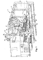
- Figure 1 illustrates a three pole air circuit breaker that includes one embodiment of a carrier link insulator.
- Figures 2 and 2A are exploded views of carrier components for one pole of the three pole air circuit breaker shown in Figure 1 .
- Figure 3 is a cutaway perspective view of the three pole air circuit breaker shown in Figure 1 that reveals the carrier components for one pole of the breaker in the breaker housing.
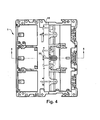
- Figure 4 is a front view of a three pole air circuit breaker that includes the pole shown in Figure 1 and that indicates a cross section to be shown in Figures 5-7 .
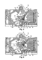
- Figure 5 is a cross section of the air circuit breaker taken along 5-5 as indicated in Figure 4 with a pole assembly in a closed or conducting position.
- Figure 6 is a cross section of the air circuit breaker taken along 5-5 as indicated in Figure 4 with a pole assembly in an intermediate contact separation position.
- Figure 7 is a cross section of the air circuit breaker taken along 5-5 as indicated in Figure 4 with a pole assembly in an open or non-conducting position.
- Figures 8 and 8A illustrate are fragmentary perspective views of a three pole air circuit breaker that includes another embodiment of a carrier link insulator.
- the air circuit breaker includes a housing 3 (shown in dashed line) that forms three pole chambers 4 ,5, 6, each configured to house a circuit breaker pole 10 (only one pole 10 is shown in solid line in Figure 1 ).
- An operating mechanism 15 is mounted to a front end of the housing 3. The operating mechanism 15 is common to all three circuit breaker poles 10 and is connected to the individual poles by a pole shaft 33 that has a drive lobe 35 for each pole.
- the drive lobe 35 is pivotally connected to a pair of carrier drive links 37 that translate motion of the drive lobe 35 into motion of pole components to separate the pole's contacts.
- the operating mechanism 15 includes a trip unit (not shown) that actuates the operating mechanism to open all the poles of the circuit breaker through rotation of the pole shaft 33 in response to predetermined characteristics of the current flowing through the circuit breaker.
- the operating mechanism 15 may be manually actuated by way of a switch lobe portion 36.
- the switch lobe portion 36 is connected to one or more manually operable switches (not shown) that are accessible outside the housing 3.
- the pole 10 which will be described in more detail below, includes a stationary contact assembly 25 configured to be connected to a line conductor (not shown) that projects rearwardly from the housing 3.
- the pole 10 also includes a contact carrier 40 that is operable to carry a moveable contact assembly 45 away from the stationary contact assembly 25.
- the moveable contact assembly 45 includes a plurality of contact fingers 47 that are pivotally mounted to the contact carrier 40. When the circuit breaker is closed, the moveable contact assembly 45 provides a current path between the stationary contact assembly 25 and a load conductor connector assembly 65 configured to be connected to a load conductor (not shown).
- the current path includes a stationary contact 27, a moveable contact 42 and a flexible shunt (not shown) connected to bottom end 49 shunt connection feature ( Figure 5 ) of the contact fingers 47.
- a moving seal 50 is also pivotally mounted to the contact carrier 40.
- the moving seal 50 includes a sealing surface 52 that forms one portion of a sealed arc chamber (not visible in Figure 1 , see Figures 5-7 ).
- the carrier drive links 37 connect to a carrier housing 46 that houses various components of the contact carrier 40 and co-acts with the moveable contact assembly 45 to open and close the contacts, as will be described in more detail below.
- a clearance opening 46a ( Figure 2 ) is typically present in the carrier housing 46 to provide clearance for installation of the carrier drive link 37 into the carrier housing.
- an insulator plug 48 is pressed into the clearance opening 46a in the carrier housing 46 to insulate the carrier drive links 37 from arcing that occurs in the arc chamber.
- a front surface of the carrier housing 46 is positioned within the arc chamber when the contacts 27, 42 are closed and moves out of the arc chamber when the contacts open as shown in Figure 7 . Because the carrier drive links 37 connect to the front carrier housing 46, without the plug 48 the carrier drive links would be exposed to the arc chamber when the contacts first open, providing an arc path and possible short circuit to the pole shaft 33.
- FIGS 2 and 2A illustrate a circuit breaker pole 110 with the insulator plug 48 a carrier drive links 37 shown separately.
- the carrier drive links 37 are connected to one another by way of a key rod 38 that is inserted through corresponding key openings in the drive lines.
- the carrier drive links 37 pivotally connect to the drive lobe 35 with a pin (not shown) inserted through top openings 95.
- the insulator plug includes a notched flat front portion 91 having a notch 92 and a U-shaped portion 93.
- the U-shaped portion 93 is positioned midway within the notch 92 and projects rearward from the flat front portion 91.
- the flat front portion 91 is configured to be press fit into the clearance opening 46a once the carrier drive links 37 are installed in the carrier housing 46.
- the U-shaped portion 93 is configured to be positioned between the carrier drive links 37 and to surround the key rod 38.
- the U-shaped portion 93 includes a front face 93a that is coplanar with a front face of the flat front portion 91.
- the insulator plug 48 may be molded as a single piece from an insulating material that provides sufficient heat resistance. In one embodiment, the insulator plug is molded of glass filled polyester.
- the front face 91 a and the front face 93a are aligned flush with a front face of the carrier housing 46 so that the insulator plug 48 does not interfere with normal operation of the circuit breaker.
- Clearance between the U-shaped portion 91 and the notch 92 provides clearance for the carrier drive links 37.
- the U-shaped portion 93 extends above the flat front portion 91 so that the flat front portion 93a abuts a portion on the circuit breaker housing 23 that forms part of the arc chamber (see Figures 5-7 ) when the contacts are closed.
- the circuit breaker housing 23 will press the insulator plug 48 into the carrier housing 46 should it move out of flush with the carrier housing.
- FIG 4 is a front view of the air circuit breaker 1.
- Section 5-5 is indicated in Figure 4 and will be used for the cross section views of a pole 110 shown in Figures 5-7 .
- the pole 110 can be seen positioned within an arc chamber 13.
- the arc chamber which is substantially closed to so that it can be pressurized, includes an outlet 18 through which arc gases may pass.
- the pole 110 is in a closed position so that current may be conducted from the stationary contact assembly 25 to the load connector assembly 65.
- the contact fingers 47 on the moveable contact assembly 45 are positioned so that the moveable contacts 42 abut the stationary contacts 27.
- Springs 74 urge the contact fingers 47 into the closed position.
- the insulator plug 48 is position partially within the arc chamber 13.
- the flat front portion 91 is within the arc chamber while the U shaped portion 93 is only partially within the arc chamber.
- a top portion of the U shaped portion front face 93a abuts and may contact the circuit breaker housing 23.
- the moveable contacts 42 are fixed to the contact fingers 47 about midway between the pivot pin 51 and a first or free end 41.
- a shunt connection feature 49 on the contact fingers 47 is adapted to be connected to a flexible shunt (not shown) that connects the contact fingers 47 to the load conductor connector assembly 65.
- Adjacent to the free end 41 of the contact fingers is an arc toe 43 that forms a moveable arcing contact which cooperates with an arc runner 39 to guide the arc from into an arc chute 17 in the arc chamber 13 to be extinguished.
- the moving seal 150 is also pivotally mounted to the pivot pin 51 on the contact carrier 40. In the closed position, the moving seal 150 is positioned down below the stationary contact 27.
- Figure 6 illustrates the circuit breaker pole 110 as it begins to open in response to rotation of the shaft 33 that acts upon the linkage between the drive lobe 35 and the carrier drive link 37 to rotate the contact carrier 40.
- An arc chamber inlet 16 is created by the movement of the contact carrier 40.
- the contact carrier 40 begins to rotate counter clockwise and the springs 74 rock the contact fingers 47 clockwise so that arc toe 43 contacts the arc runner while the moveable contacts 42 are separated from the stationary contact 27.
- the insulator plug 48 is moving so that will no longer be positioned within the arc chamber 13. Any arcing that occurs during contact separation will be prevented from contacting the carrier drive links 37 by the insulator plug.
- the flat front portion 91 and the U shaped portion front face 93a abut and may contact the circuit breaker housing 23.
- the moving seal 150 rotates up toward the stationary contacts 27 to the position shown in Figure 7 .
- the moving seal 150 is positioned to seal between the contact fingers 47 and to place the arc creepage surface 152 just below the stationary contact 27 to close off the arc chamber inlet 16 so that the arc can be extinguished.
- the insulator plug 48 is positioned outside the arc chamber 13.
- the flat front portion 91 a and the U shaped portion front face 93a abut and may contact the circuit breaker housing 23.
- FIGS 8 and 8A illustrate an alternative embodiment of a carrier link insulator 148.
- the carrier link insulator 148 includes a pair of barrier clips 151 that secure a flexible barrier member 152.
- the barrier clips 151 each have a ring tab 155 that is configured to surround the key rod 38 between the drive links 37 to couple the insulator 148 to the drive links.
- the barrier 152 is made of a dielectric material such as fish paper and is configured to flex when the drive links 37 move the contact carrier 40 along the excursion between the contact closed and contact open positions.
Landscapes
- Arc-Extinguishing Devices That Are Switches (AREA)
Abstract
Description
- Electrical switching apparatus for power distribution systems include devices such as circuit breakers, network protectors, transfer switches and disconnect switches. A common type of circuit breaker is the air circuit breaker, which uses a flow of gas to extinguish the arc caused by separation of the contacts. The flow of gas may be provided by a source of compressed gas or by air exiting a sealed arc chamber that is pressurized when the contacts separate. When the circuit breaker contacts are closed, a portion of the drive linkage that actuates the contact separation mechanism may be positioned within the arc chamber. Thus arcing that occurs during separation may electrically contact the drive linkage, creating a potential short circuit condition.
- In one embodiment, an apparatus includes a contact carrier configured to be actuated by a carrier drive link to carry one or more moveable contacts along an excursion between a contact closed position in which the moveable contacts electrically contact corresponding stationary contacts and a contact open position in which the moveable contacts do not contact the corresponding stationary contacts. The contact carrier includes a carrier housing and a carrier link insulator. The carrier housing is configured to house the carrier drive link, the carrier housing further comprising a front face that is positioned within an arc chamber during at least a portion of the carrier excursion. The carrier link insulator is coupled to the carrier housing. The carrier link insulator includes an electrically insulating material and is being located in an arc path between the arc chamber and the carrier drive link.
- In one particular embodiment, the carrier link insulator is an insulator plug configured to be press fit in an opening in the carrier housing front face. The insulator plug includes a plug front face that is substantially flush with the carrier housing front face when the insulator plug is fitted into the carrier housing. The insulator plug may also include a notched flat front portion and a U-shaped portion in which the U-shaped portion is positioned midway within a notch in the notched flat front portion and is configured to be positioned around at least a portion of the carrier drive link. The U-shaped portion may include a front face that aligns flush with a front face of the notched flat front portion to form the plug front face and extends above the front face of the notched flat front portion so that the plug front face abuts a circuit breaker housing the forms part of the arc chamber throughout the excursion.
- In another embodiment, the carrier link insulator includes a flexible barrier made of dielectric material coupled to the carrier drive link and configured to flex when the drive line moves the contact carrier.
- The accompanying drawings, which are incorporated in and constitute a part of the specification, illustrate various example systems, methods, and other embodiments of various aspects of the invention. One of ordinary skill in the art will appreciate that in some embodiments one element may be designed as multiple elements, multiple elements may be designed as one element, an element shown as an internal component of another element may be implemented as an external component and vice versa, and so on. Furthermore, elements may not be drawn to scale.
-
Figure 1 illustrates a three pole air circuit breaker that includes one embodiment of a carrier link insulator. -
Figures 2 and 2A are exploded views of carrier components for one pole of the three pole air circuit breaker shown inFigure 1 . -
Figure 3 is a cutaway perspective view of the three pole air circuit breaker shown inFigure 1 that reveals the carrier components for one pole of the breaker in the breaker housing. -
Figure 4 is a front view of a three pole air circuit breaker that includes the pole shown inFigure 1 and that indicates a cross section to be shown inFigures 5-7 . -
Figure 5 is a cross section of the air circuit breaker taken along 5-5 as indicated inFigure 4 with a pole assembly in a closed or conducting position. -
Figure 6 is a cross section of the air circuit breaker taken along 5-5 as indicated inFigure 4 with a pole assembly in an intermediate contact separation position. -
Figure 7 is a cross section of the air circuit breaker taken along 5-5 as indicated inFigure 4 with a pole assembly in an open or non-conducting position. -
Figures 8 and 8A illustrate are fragmentary perspective views of a three pole air circuit breaker that includes another embodiment of a carrier link insulator. - An
air circuit breaker 1 is illustrated inFigure 1 . The air circuit breaker includes a housing 3 (shown in dashed line) that forms threepole chambers pole 10 is shown in solid line inFigure 1 ). Anoperating mechanism 15 is mounted to a front end of thehousing 3. Theoperating mechanism 15 is common to all threecircuit breaker poles 10 and is connected to the individual poles by apole shaft 33 that has adrive lobe 35 for each pole. Thedrive lobe 35 is pivotally connected to a pair ofcarrier drive links 37 that translate motion of thedrive lobe 35 into motion of pole components to separate the pole's contacts. Theoperating mechanism 15 includes a trip unit (not shown) that actuates the operating mechanism to open all the poles of the circuit breaker through rotation of thepole shaft 33 in response to predetermined characteristics of the current flowing through the circuit breaker. In addition, theoperating mechanism 15 may be manually actuated by way of aswitch lobe portion 36. Theswitch lobe portion 36 is connected to one or more manually operable switches (not shown) that are accessible outside thehousing 3. - The
pole 10, which will be described in more detail below, includes astationary contact assembly 25 configured to be connected to a line conductor (not shown) that projects rearwardly from thehousing 3. Thepole 10 also includes acontact carrier 40 that is operable to carry amoveable contact assembly 45 away from thestationary contact assembly 25. Themoveable contact assembly 45 includes a plurality ofcontact fingers 47 that are pivotally mounted to thecontact carrier 40. When the circuit breaker is closed, themoveable contact assembly 45 provides a current path between thestationary contact assembly 25 and a loadconductor connector assembly 65 configured to be connected to a load conductor (not shown). The current path includes astationary contact 27, amoveable contact 42 and a flexible shunt (not shown) connected tobottom end 49 shunt connection feature (Figure 5 ) of thecontact fingers 47. A movingseal 50 is also pivotally mounted to thecontact carrier 40. The movingseal 50 includes a sealing surface 52 that forms one portion of a sealed arc chamber (not visible inFigure 1 , seeFigures 5-7 ). - The
carrier drive links 37 connect to acarrier housing 46 that houses various components of thecontact carrier 40 and co-acts with themoveable contact assembly 45 to open and close the contacts, as will be described in more detail below. A clearance opening 46a (Figure 2 ) is typically present in thecarrier housing 46 to provide clearance for installation of thecarrier drive link 37 into the carrier housing. According one embodiment of the present invention, aninsulator plug 48 is pressed into the clearance opening 46a in thecarrier housing 46 to insulate thecarrier drive links 37 from arcing that occurs in the arc chamber. As can be seen best inFigure 5 , a front surface of thecarrier housing 46 is positioned within the arc chamber when thecontacts Figure 7 . Because thecarrier drive links 37 connect to thefront carrier housing 46, without theplug 48 the carrier drive links would be exposed to the arc chamber when the contacts first open, providing an arc path and possible short circuit to thepole shaft 33. -
Figures 2 and 2A illustrate acircuit breaker pole 110 with the insulator plug 48 acarrier drive links 37 shown separately. Thecarrier drive links 37 are connected to one another by way of akey rod 38 that is inserted through corresponding key openings in the drive lines. Thecarrier drive links 37 pivotally connect to thedrive lobe 35 with a pin (not shown) inserted throughtop openings 95. The insulator plug includes a notchedflat front portion 91 having anotch 92 and aU-shaped portion 93. The U-shapedportion 93 is positioned midway within thenotch 92 and projects rearward from theflat front portion 91. Theflat front portion 91 is configured to be press fit into the clearance opening 46a once thecarrier drive links 37 are installed in thecarrier housing 46. The U-shapedportion 93 is configured to be positioned between thecarrier drive links 37 and to surround thekey rod 38. The U-shapedportion 93 includes afront face 93a that is coplanar with a front face of theflat front portion 91. Theinsulator plug 48 may be molded as a single piece from an insulating material that provides sufficient heat resistance. In one embodiment, the insulator plug is molded of glass filled polyester. - Referring now to
Figure 3 , when theinsulator plug 48 is installed in thecarrier housing 46, thefront face 91 a and thefront face 93a are aligned flush with a front face of thecarrier housing 46 so that theinsulator plug 48 does not interfere with normal operation of the circuit breaker. Clearance between the U-shapedportion 91 and thenotch 92 provides clearance for thecarrier drive links 37. The U-shapedportion 93 extends above theflat front portion 91 so that theflat front portion 93a abuts a portion on thecircuit breaker housing 23 that forms part of the arc chamber (seeFigures 5-7 ) when the contacts are closed. As will be seen inFigures 5-7 , throughout the range of motion of thecontact carrier 40, thecircuit breaker housing 23 will press theinsulator plug 48 into thecarrier housing 46 should it move out of flush with the carrier housing. -
Figure 4 is a front view of theair circuit breaker 1. Section 5-5 is indicated inFigure 4 and will be used for the cross section views of apole 110 shown inFigures 5-7 . Referring now toFigure 5 , thepole 110 can be seen positioned within anarc chamber 13. The arc chamber, which is substantially closed to so that it can be pressurized, includes anoutlet 18 through which arc gases may pass. InFigure 5 thepole 110 is in a closed position so that current may be conducted from thestationary contact assembly 25 to theload connector assembly 65. Thecontact fingers 47 on themoveable contact assembly 45 are positioned so that themoveable contacts 42 abut thestationary contacts 27.Springs 74 urge thecontact fingers 47 into the closed position. Theinsulator plug 48 is position partially within thearc chamber 13. Theflat front portion 91 is within the arc chamber while the U shapedportion 93 is only partially within the arc chamber. A top portion of the U shapedportion front face 93a abuts and may contact thecircuit breaker housing 23. - The
moveable contacts 42 are fixed to thecontact fingers 47 about midway between thepivot pin 51 and a first orfree end 41. Ashunt connection feature 49 on thecontact fingers 47 is adapted to be connected to a flexible shunt (not shown) that connects thecontact fingers 47 to the loadconductor connector assembly 65. Adjacent to thefree end 41 of the contact fingers is anarc toe 43 that forms a moveable arcing contact which cooperates with anarc runner 39 to guide the arc from into anarc chute 17 in thearc chamber 13 to be extinguished. The movingseal 150 is also pivotally mounted to thepivot pin 51 on thecontact carrier 40. In the closed position, the movingseal 150 is positioned down below thestationary contact 27. -
Figure 6 illustrates thecircuit breaker pole 110 as it begins to open in response to rotation of theshaft 33 that acts upon the linkage between thedrive lobe 35 and thecarrier drive link 37 to rotate thecontact carrier 40. Anarc chamber inlet 16 is created by the movement of thecontact carrier 40. Thecontact carrier 40 begins to rotate counter clockwise and thesprings 74 rock thecontact fingers 47 clockwise so thatarc toe 43 contacts the arc runner while themoveable contacts 42 are separated from thestationary contact 27. Theinsulator plug 48 is moving so that will no longer be positioned within thearc chamber 13. Any arcing that occurs during contact separation will be prevented from contacting the carrier drive links 37 by the insulator plug. Theflat front portion 91 and the U shapedportion front face 93a abut and may contact thecircuit breaker housing 23. - Continued rotation of the contact carrier causes the moving
seal 150 rotate up toward thestationary contacts 27 to the position shown inFigure 7 . The movingseal 150 is positioned to seal between thecontact fingers 47 and to place thearc creepage surface 152 just below thestationary contact 27 to close off thearc chamber inlet 16 so that the arc can be extinguished. Theinsulator plug 48 is positioned outside thearc chamber 13. Theflat front portion 91 a and the U shapedportion front face 93a abut and may contact thecircuit breaker housing 23. -
Figures 8 and 8A illustrate an alternative embodiment of acarrier link insulator 148. Thecarrier link insulator 148 includes a pair of barrier clips 151 that secure aflexible barrier member 152. The barrier clips 151 each have aring tab 155 that is configured to surround thekey rod 38 between the drive links 37 to couple theinsulator 148 to the drive links. Thebarrier 152 is made of a dielectric material such as fish paper and is configured to flex when the drive links 37 move thecontact carrier 40 along the excursion between the contact closed and contact open positions. - To the extent that the term "or" is employed in the detailed description or claims (e.g., A or B) it is intended to mean "A or B or both". The term "and/or" is used in the same manner, meaning "A or B or both". When the applicants intend to indicate "only A or B but not both" then the term "only A or B but not both" will be employed. Thus, use of the term "or" herein is the inclusive, and not the exclusive use. See, Bryan A. Garner, A Dictionary of Modern Legal Usage 624 (2d. Ed. 1995).
- To the extent that the phrase "one or more of, A, B, and C" is employed herein, (e.g., a data store configured to store one or more of, A, B, and C) it is intended to convey the set of possibilities A, B, C, AB, AC, BC, and/or ABC (e.g., the data store may store only A, only B, only C, A&B, A&C, B&C, and/or A&B&C). It is not intended to require one of A, one of B, and one of C. When the applicants intend to indicate "at least one of A, at least one of B, and at least one of C", then the phrasing "at least one of A, at least one of B, and at least one of C" will be employed.
Claims (15)
- An apparatus comprising:a contact carrier configured to be actuated by a carrier drive link to carry one or more moveable contacts along an excursion between a contact closed position in which the moveable contacts electrically contact corresponding stationary contacts and a contact open position in which the moveable contacts do not contact the corresponding stationary contacts, the contact carrier comprising:a carrier housing configured to house the carrier drive link, the carrier housing further comprising a front face that is positioned within an arc chamber during at least a portion of the carrier excursion; anda carrier link insulator coupled to the carrier housing, the carrier link insulator comprising an electrically insulating material and being located in an arc path between the arc chamber and the carrier drive link.
- The apparatus of claim 1 where the carrier link insulator comprises an insulator plug configured to be press fit in an opening in the carrier housing front face.
- The apparatus of claim 2 where the insulator plug comprises a plug front face that is substantially flush with the carrier housing front face when the insulator plug is fitted into the carrier housing.
- The apparatus of claim 3 where the insulator plug comprises:notched flat front portion;a U-shaped portion;where the U-shaped portion is positioned midway within a notch in the notched flat front portion; andwhere the U-shaped portion is configured to be positioned around at least a portion of the carrier drive link.
- The apparatus of claim 4 where the U-shaped portion comprises a front face that aligns flush with a front face of the notched flat front portion to form the plug front face.
- The apparatus of claim 5 where the front face of the U-shaped portion extends above the front face of the notched flat front portion such that the plug front face abuts a circuit breaker housing the forms part of the arc chamber throughout the excursion.
- The apparatus of claim 1 where the carrier link insulator comprises a flexible barrier comprised of dielectric material coupled to the carrier drive link and configured to flex when the carrier drive link moves the contact carrier.
- A circuit breaker comprising:a substantially closed arc chamber enclosing a pair of separable contact assemblies comprising a moveable contacts and a stationary contact, where a portion of the arc chamber is formed by a circuit breaker housing; anda contact carrier coupled to a carrier drive link, the contact carrier configured to carry the moveable contact along an excursion between a contact closed position in which the moveable contact electrically contacts the stationary contact and a contact open position in which the moveable contact does not contact the corresponding stationary contact, the contact carrier comprising:a carrier housing configured to house the carrier drive link, the carrier housing further comprising a front face that is positioned within an arc chamber during at least a portion of the carrier excursion; anda carrier link insulator coupled to the carrier housing, the carrier link insulator comprising an electrically insulating material and being located in an arc path between the arc chamber and the carrier drive link.
- The circuit breaker of claim 8 where the carrier link insulator comprises an insulator plug configured to be press fit in an opening in the carrier housing front face.
- The circuit breaker of claim 9 where the insulator plug comprises a plug front face that is substantially flush with the carrier housing front face when the insulator plug is fitted into the carrier housing.
- The circuit breaker of claim 10 where the insulator plug comprises:notched flat front portion;a U-shaped portion;where the U-shaped portion is positioned midway within a notch in the notched flat front portion; andwhere the U-shaped portion is configured to be positioned around at least a portion of the carrier drive link.
- The circuit breaker of claim 11 where the U-shaped portion comprises a front face that aligns flush with a front face of the notched flat front portion to form the plug front face.
- The circuit breaker of claim 12 where the front face of the U-shaped portion extends above the front face of the notched flat front portion such that the plug front face abuts a circuit breaker housing the forms part of the arc chamber throughout the excursion.
- The circuit breaker of claim 8 where the carrier link insulator comprises a flexible barrier comprised of dielectric material coupled to the carrier drive link and configured to flex when the carrier drive link moves the contact carrier.
- A circuit breaker apparatus comprising means for electrically insulating a carrier drive link from an arc chamber,
where the means for electrically insulating optionally comprises an insulator plug or
a flexible barrier comprised of dielectric material.
Applications Claiming Priority (1)
| Application Number | Priority Date | Filing Date | Title |
|---|---|---|---|
| US13/172,959 US8415580B2 (en) | 2011-06-30 | 2011-06-30 | Carrier link insulator for a circuit breaker |
Publications (2)
| Publication Number | Publication Date |
|---|---|
| EP2541573A1 true EP2541573A1 (en) | 2013-01-02 |
| EP2541573B1 EP2541573B1 (en) | 2017-08-23 |
Family
ID=46507840
Family Applications (1)
| Application Number | Title | Priority Date | Filing Date |
|---|---|---|---|
| EP12004912.7A Active EP2541573B1 (en) | 2011-06-30 | 2012-07-02 | Carrier link insulator for a circuit breaker |
Country Status (5)
| Country | Link |
|---|---|
| US (1) | US8415580B2 (en) |
| EP (1) | EP2541573B1 (en) |
| CN (1) | CN102856125B (en) |
| CA (1) | CA2782919C (en) |
| ZA (1) | ZA201204785B (en) |
Cited By (3)
| Publication number | Priority date | Publication date | Assignee | Title |
|---|---|---|---|---|
| CN104409248A (en) * | 2014-11-28 | 2015-03-11 | 德力西电气有限公司 | Contact system with automatic arc blowing function |
| WO2015069831A1 (en) * | 2013-11-08 | 2015-05-14 | Eaton Corporation | Moving seal with arc creepage surface for an air circuit breaker |
| US9293282B2 (en) | 2010-06-16 | 2016-03-22 | Eaton Corporation | Moving seal with arc creepage surface for an air circuit breaker |
Families Citing this family (3)
| Publication number | Priority date | Publication date | Assignee | Title |
|---|---|---|---|---|
| CN104350560B (en) * | 2013-02-27 | 2017-09-15 | 通用电气公司 | Electrical transfer switch system |
| FR3036841B1 (en) * | 2015-05-28 | 2017-06-23 | Schneider Electric Ind Sas | MOBILE POLE AND CUTTING APPARATUS |
| CN107546079A (en) * | 2016-06-23 | 2018-01-05 | 上海良信电器股份有限公司 | A kind of structure-improved of low-voltage breaker contact system |
Citations (7)
| Publication number | Priority date | Publication date | Assignee | Title |
|---|---|---|---|---|
| EP0222690A1 (en) * | 1985-11-13 | 1987-05-20 | Siemens Aktiengesellschaft | Contact arrangement for low-voltage circuit breakers with a movable insulating body |
| EP0225207A1 (en) * | 1985-10-31 | 1987-06-10 | Merlin Gerin | Cinematic transmission chain between the control mechanism and the poles of an electric circuit breaker with a moulded insulating casing |
| EP0489986A1 (en) * | 1990-12-14 | 1992-06-17 | Siemens Aktiengesellschaft | Low tension high power circuit breaker with an insulating connection means and an insulating shield |
| JPH05303930A (en) * | 1992-02-26 | 1993-11-16 | Mitsubishi Electric Corp | Circuit breaker |
| US5361052A (en) * | 1993-07-02 | 1994-11-01 | General Electric Company | Industrial-rated circuit breaker having universal application |
| EP0955658A2 (en) * | 1998-05-07 | 1999-11-10 | Eaton Corporation | Electrical switching apparatus with improved contact arm carrier arrangement |
| EP1968084A2 (en) * | 2006-12-29 | 2008-09-10 | LS Industrial Systems Co., Ltd | Apparatus for connecting link pin of circuit breaker |
Family Cites Families (3)
| Publication number | Priority date | Publication date | Assignee | Title |
|---|---|---|---|---|
| IT1289482B1 (en) * | 1996-12-20 | 1998-10-15 | Sace Spa | CURRENT SWITCH WITH MOVABLE CONTACTS |
| US20070268100A1 (en) * | 2006-05-18 | 2007-11-22 | Eaton Corporation | Electrical switching apparatus, and movable contact assembly and shield therefor |
| US8183490B2 (en) * | 2009-09-28 | 2012-05-22 | Eaton Corporation | Shield apparatus for circuit breaker |
-
2011
- 2011-06-30 US US13/172,959 patent/US8415580B2/en active Active
-
2012
- 2012-06-27 ZA ZA2012/04785A patent/ZA201204785B/en unknown
- 2012-06-29 CA CA2782919A patent/CA2782919C/en active Active
- 2012-07-02 EP EP12004912.7A patent/EP2541573B1/en active Active
- 2012-07-02 CN CN201210282518.XA patent/CN102856125B/en active Active
Patent Citations (7)
| Publication number | Priority date | Publication date | Assignee | Title |
|---|---|---|---|---|
| EP0225207A1 (en) * | 1985-10-31 | 1987-06-10 | Merlin Gerin | Cinematic transmission chain between the control mechanism and the poles of an electric circuit breaker with a moulded insulating casing |
| EP0222690A1 (en) * | 1985-11-13 | 1987-05-20 | Siemens Aktiengesellschaft | Contact arrangement for low-voltage circuit breakers with a movable insulating body |
| EP0489986A1 (en) * | 1990-12-14 | 1992-06-17 | Siemens Aktiengesellschaft | Low tension high power circuit breaker with an insulating connection means and an insulating shield |
| JPH05303930A (en) * | 1992-02-26 | 1993-11-16 | Mitsubishi Electric Corp | Circuit breaker |
| US5361052A (en) * | 1993-07-02 | 1994-11-01 | General Electric Company | Industrial-rated circuit breaker having universal application |
| EP0955658A2 (en) * | 1998-05-07 | 1999-11-10 | Eaton Corporation | Electrical switching apparatus with improved contact arm carrier arrangement |
| EP1968084A2 (en) * | 2006-12-29 | 2008-09-10 | LS Industrial Systems Co., Ltd | Apparatus for connecting link pin of circuit breaker |
Non-Patent Citations (1)
| Title |
|---|
| BRYAN A. GARNER: "A Dictionary of Modern Legal Usage", 1995, pages: 624 |
Cited By (3)
| Publication number | Priority date | Publication date | Assignee | Title |
|---|---|---|---|---|
| US9293282B2 (en) | 2010-06-16 | 2016-03-22 | Eaton Corporation | Moving seal with arc creepage surface for an air circuit breaker |
| WO2015069831A1 (en) * | 2013-11-08 | 2015-05-14 | Eaton Corporation | Moving seal with arc creepage surface for an air circuit breaker |
| CN104409248A (en) * | 2014-11-28 | 2015-03-11 | 德力西电气有限公司 | Contact system with automatic arc blowing function |
Also Published As
| Publication number | Publication date |
|---|---|
| CA2782919A1 (en) | 2012-12-30 |
| ZA201204785B (en) | 2013-03-27 |
| US20130001202A1 (en) | 2013-01-03 |
| CN102856125A (en) | 2013-01-02 |
| US8415580B2 (en) | 2013-04-09 |
| CN102856125B (en) | 2017-03-01 |
| CA2782919C (en) | 2019-06-04 |
| EP2541573B1 (en) | 2017-08-23 |
Similar Documents
| Publication | Publication Date | Title |
|---|---|---|
| CA2782919C (en) | Carrier link insulator for a circuit breaker | |
| EP2398033A2 (en) | Moving seal with arc creepage surface for an air circuit breaker | |
| US8779318B2 (en) | Switching device and a switchgear | |
| CN101689446A (en) | Electrical Installation Distribution Appliances | |
| CA2271247C (en) | Electrical switching apparatus having arc runner integral with stationary arcing contact | |
| US8847095B2 (en) | High-voltage switching device | |
| US20110193660A1 (en) | Movable contactor assembly for current limiting type molded case circuit breaker | |
| CN1770351A (en) | Arc extinguisher assembly for mould cased circuit breaker | |
| KR101463374B1 (en) | A switching device and a switchgear | |
| US8735758B2 (en) | Circuit breaker having dual arc chamber | |
| US7994882B2 (en) | Space allocation within a circuit breaker | |
| KR101562482B1 (en) | A switching device and a switchgear | |
| CN101083186A (en) | Electrical switching apparatus, and movable contact assemblyand shield therefor | |
| US8164018B2 (en) | Circuit breaker arc chambers and methods for operating same | |
| CA1076175A (en) | Combination cover interlock and trip actuator | |
| US8592709B2 (en) | Current path arrangement for a circuit breaker | |
| US6541727B2 (en) | Molded case circuit breaker including vacuum switch assembly | |
| CN101071701A (en) | Circuit breaker | |
| CN113823539A (en) | Arc extinguishing system of circuit breaker | |
| JP4499890B2 (en) | Circuit breaker | |
| CN221508069U (en) | Two-pole breaker | |
| CN215869223U (en) | Circuit breaker | |
| KR100732508B1 (en) | Pressure trip device of circuit breaker | |
| EP1178509A3 (en) | Magnetothermal electrical circuit breaker |
Legal Events
| Date | Code | Title | Description |
|---|---|---|---|
| PUAI | Public reference made under article 153(3) epc to a published international application that has entered the european phase |
Free format text: ORIGINAL CODE: 0009012 |
|
| AK | Designated contracting states |
Kind code of ref document: A1 Designated state(s): AL AT BE BG CH CY CZ DE DK EE ES FI FR GB GR HR HU IE IS IT LI LT LU LV MC MK MT NL NO PL PT RO RS SE SI SK SM TR |
|
| AX | Request for extension of the european patent |
Extension state: BA ME |
|
| 17P | Request for examination filed |
Effective date: 20130702 |
|
| RBV | Designated contracting states (corrected) |
Designated state(s): AL AT BE BG CH CY CZ DE DK EE ES FI FR GB GR HR HU IE IS IT LI LT LU LV MC MK MT NL NO PL PT RO RS SE SI SK SM TR |
|
| 17Q | First examination report despatched |
Effective date: 20160223 |
|
| GRAP | Despatch of communication of intention to grant a patent |
Free format text: ORIGINAL CODE: EPIDOSNIGR1 |
|
| INTG | Intention to grant announced |
Effective date: 20170109 |
|
| GRAS | Grant fee paid |
Free format text: ORIGINAL CODE: EPIDOSNIGR3 |
|
| GRAA | (expected) grant |
Free format text: ORIGINAL CODE: 0009210 |
|
| AK | Designated contracting states |
Kind code of ref document: B1 Designated state(s): AL AT BE BG CH CY CZ DE DK EE ES FI FR GB GR HR HU IE IS IT LI LT LU LV MC MK MT NL NO PL PT RO RS SE SI SK SM TR |
|
| REG | Reference to a national code |
Ref country code: GB Ref legal event code: FG4D |
|
| REG | Reference to a national code |
Ref country code: CH Ref legal event code: EP |
|
| REG | Reference to a national code |
Ref country code: AT Ref legal event code: REF Ref document number: 922171 Country of ref document: AT Kind code of ref document: T Effective date: 20170915 |
|
| REG | Reference to a national code |
Ref country code: IE Ref legal event code: FG4D |
|
| REG | Reference to a national code |
Ref country code: DE Ref legal event code: R096 Ref document number: 602012036167 Country of ref document: DE |
|
| REG | Reference to a national code |
Ref country code: NL Ref legal event code: MP Effective date: 20170823 |
|
| REG | Reference to a national code |
Ref country code: LT Ref legal event code: MG4D |
|
| REG | Reference to a national code |
Ref country code: AT Ref legal event code: MK05 Ref document number: 922171 Country of ref document: AT Kind code of ref document: T Effective date: 20170823 |
|
| PG25 | Lapsed in a contracting state [announced via postgrant information from national office to epo] |
Ref country code: NO Free format text: LAPSE BECAUSE OF FAILURE TO SUBMIT A TRANSLATION OF THE DESCRIPTION OR TO PAY THE FEE WITHIN THE PRESCRIBED TIME-LIMIT Effective date: 20171123 Ref country code: AT Free format text: LAPSE BECAUSE OF FAILURE TO SUBMIT A TRANSLATION OF THE DESCRIPTION OR TO PAY THE FEE WITHIN THE PRESCRIBED TIME-LIMIT Effective date: 20170823 Ref country code: FI Free format text: LAPSE BECAUSE OF FAILURE TO SUBMIT A TRANSLATION OF THE DESCRIPTION OR TO PAY THE FEE WITHIN THE PRESCRIBED TIME-LIMIT Effective date: 20170823 Ref country code: LT Free format text: LAPSE BECAUSE OF FAILURE TO SUBMIT A TRANSLATION OF THE DESCRIPTION OR TO PAY THE FEE WITHIN THE PRESCRIBED TIME-LIMIT Effective date: 20170823 Ref country code: HR Free format text: LAPSE BECAUSE OF FAILURE TO SUBMIT A TRANSLATION OF THE DESCRIPTION OR TO PAY THE FEE WITHIN THE PRESCRIBED TIME-LIMIT Effective date: 20170823 Ref country code: NL Free format text: LAPSE BECAUSE OF FAILURE TO SUBMIT A TRANSLATION OF THE DESCRIPTION OR TO PAY THE FEE WITHIN THE PRESCRIBED TIME-LIMIT Effective date: 20170823 Ref country code: SE Free format text: LAPSE BECAUSE OF FAILURE TO SUBMIT A TRANSLATION OF THE DESCRIPTION OR TO PAY THE FEE WITHIN THE PRESCRIBED TIME-LIMIT Effective date: 20170823 |
|
| PG25 | Lapsed in a contracting state [announced via postgrant information from national office to epo] |
Ref country code: LV Free format text: LAPSE BECAUSE OF FAILURE TO SUBMIT A TRANSLATION OF THE DESCRIPTION OR TO PAY THE FEE WITHIN THE PRESCRIBED TIME-LIMIT Effective date: 20170823 Ref country code: GR Free format text: LAPSE BECAUSE OF FAILURE TO SUBMIT A TRANSLATION OF THE DESCRIPTION OR TO PAY THE FEE WITHIN THE PRESCRIBED TIME-LIMIT Effective date: 20171124 Ref country code: ES Free format text: LAPSE BECAUSE OF FAILURE TO SUBMIT A TRANSLATION OF THE DESCRIPTION OR TO PAY THE FEE WITHIN THE PRESCRIBED TIME-LIMIT Effective date: 20170823 Ref country code: PL Free format text: LAPSE BECAUSE OF FAILURE TO SUBMIT A TRANSLATION OF THE DESCRIPTION OR TO PAY THE FEE WITHIN THE PRESCRIBED TIME-LIMIT Effective date: 20170823 Ref country code: IS Free format text: LAPSE BECAUSE OF FAILURE TO SUBMIT A TRANSLATION OF THE DESCRIPTION OR TO PAY THE FEE WITHIN THE PRESCRIBED TIME-LIMIT Effective date: 20171223 Ref country code: BG Free format text: LAPSE BECAUSE OF FAILURE TO SUBMIT A TRANSLATION OF THE DESCRIPTION OR TO PAY THE FEE WITHIN THE PRESCRIBED TIME-LIMIT Effective date: 20171123 Ref country code: RS Free format text: LAPSE BECAUSE OF FAILURE TO SUBMIT A TRANSLATION OF THE DESCRIPTION OR TO PAY THE FEE WITHIN THE PRESCRIBED TIME-LIMIT Effective date: 20170823 |
|
| PG25 | Lapsed in a contracting state [announced via postgrant information from national office to epo] |
Ref country code: RO Free format text: LAPSE BECAUSE OF FAILURE TO SUBMIT A TRANSLATION OF THE DESCRIPTION OR TO PAY THE FEE WITHIN THE PRESCRIBED TIME-LIMIT Effective date: 20170823 Ref country code: DK Free format text: LAPSE BECAUSE OF FAILURE TO SUBMIT A TRANSLATION OF THE DESCRIPTION OR TO PAY THE FEE WITHIN THE PRESCRIBED TIME-LIMIT Effective date: 20170823 Ref country code: CZ Free format text: LAPSE BECAUSE OF FAILURE TO SUBMIT A TRANSLATION OF THE DESCRIPTION OR TO PAY THE FEE WITHIN THE PRESCRIBED TIME-LIMIT Effective date: 20170823 |
|
| REG | Reference to a national code |
Ref country code: DE Ref legal event code: R097 Ref document number: 602012036167 Country of ref document: DE |
|
| PG25 | Lapsed in a contracting state [announced via postgrant information from national office to epo] |
Ref country code: SM Free format text: LAPSE BECAUSE OF FAILURE TO SUBMIT A TRANSLATION OF THE DESCRIPTION OR TO PAY THE FEE WITHIN THE PRESCRIBED TIME-LIMIT Effective date: 20170823 Ref country code: EE Free format text: LAPSE BECAUSE OF FAILURE TO SUBMIT A TRANSLATION OF THE DESCRIPTION OR TO PAY THE FEE WITHIN THE PRESCRIBED TIME-LIMIT Effective date: 20170823 Ref country code: SK Free format text: LAPSE BECAUSE OF FAILURE TO SUBMIT A TRANSLATION OF THE DESCRIPTION OR TO PAY THE FEE WITHIN THE PRESCRIBED TIME-LIMIT Effective date: 20170823 |
|
| REG | Reference to a national code |
Ref country code: FR Ref legal event code: PLFP Year of fee payment: 7 |
|
| PLBE | No opposition filed within time limit |
Free format text: ORIGINAL CODE: 0009261 |
|
| STAA | Information on the status of an ep patent application or granted ep patent |
Free format text: STATUS: NO OPPOSITION FILED WITHIN TIME LIMIT |
|
| 26N | No opposition filed |
Effective date: 20180524 |
|
| PG25 | Lapsed in a contracting state [announced via postgrant information from national office to epo] |
Ref country code: SI Free format text: LAPSE BECAUSE OF FAILURE TO SUBMIT A TRANSLATION OF THE DESCRIPTION OR TO PAY THE FEE WITHIN THE PRESCRIBED TIME-LIMIT Effective date: 20170823 |
|
| REG | Reference to a national code |
Ref country code: CH Ref legal event code: PL |
|
| GBPC | Gb: european patent ceased through non-payment of renewal fee |
Effective date: 20180702 |
|
| PG25 | Lapsed in a contracting state [announced via postgrant information from national office to epo] |
Ref country code: MC Free format text: LAPSE BECAUSE OF FAILURE TO SUBMIT A TRANSLATION OF THE DESCRIPTION OR TO PAY THE FEE WITHIN THE PRESCRIBED TIME-LIMIT Effective date: 20170823 Ref country code: LU Free format text: LAPSE BECAUSE OF NON-PAYMENT OF DUE FEES Effective date: 20180702 |
|
| REG | Reference to a national code |
Ref country code: BE Ref legal event code: MM Effective date: 20180731 |
|
| REG | Reference to a national code |
Ref country code: IE Ref legal event code: MM4A |
|
| PG25 | Lapsed in a contracting state [announced via postgrant information from national office to epo] |
Ref country code: IE Free format text: LAPSE BECAUSE OF NON-PAYMENT OF DUE FEES Effective date: 20180702 Ref country code: LI Free format text: LAPSE BECAUSE OF NON-PAYMENT OF DUE FEES Effective date: 20180731 Ref country code: GB Free format text: LAPSE BECAUSE OF NON-PAYMENT OF DUE FEES Effective date: 20180702 Ref country code: CH Free format text: LAPSE BECAUSE OF NON-PAYMENT OF DUE FEES Effective date: 20180731 |
|
| PG25 | Lapsed in a contracting state [announced via postgrant information from national office to epo] |
Ref country code: BE Free format text: LAPSE BECAUSE OF NON-PAYMENT OF DUE FEES Effective date: 20180731 |
|
| PG25 | Lapsed in a contracting state [announced via postgrant information from national office to epo] |
Ref country code: MT Free format text: LAPSE BECAUSE OF NON-PAYMENT OF DUE FEES Effective date: 20180702 |
|
| PG25 | Lapsed in a contracting state [announced via postgrant information from national office to epo] |
Ref country code: TR Free format text: LAPSE BECAUSE OF FAILURE TO SUBMIT A TRANSLATION OF THE DESCRIPTION OR TO PAY THE FEE WITHIN THE PRESCRIBED TIME-LIMIT Effective date: 20170823 |
|
| PG25 | Lapsed in a contracting state [announced via postgrant information from national office to epo] |
Ref country code: PT Free format text: LAPSE BECAUSE OF FAILURE TO SUBMIT A TRANSLATION OF THE DESCRIPTION OR TO PAY THE FEE WITHIN THE PRESCRIBED TIME-LIMIT Effective date: 20170823 Ref country code: HU Free format text: LAPSE BECAUSE OF FAILURE TO SUBMIT A TRANSLATION OF THE DESCRIPTION OR TO PAY THE FEE WITHIN THE PRESCRIBED TIME-LIMIT; INVALID AB INITIO Effective date: 20120702 |
|
| PG25 | Lapsed in a contracting state [announced via postgrant information from national office to epo] |
Ref country code: CY Free format text: LAPSE BECAUSE OF FAILURE TO SUBMIT A TRANSLATION OF THE DESCRIPTION OR TO PAY THE FEE WITHIN THE PRESCRIBED TIME-LIMIT Effective date: 20170823 Ref country code: MK Free format text: LAPSE BECAUSE OF NON-PAYMENT OF DUE FEES Effective date: 20170823 |
|
| PG25 | Lapsed in a contracting state [announced via postgrant information from national office to epo] |
Ref country code: AL Free format text: LAPSE BECAUSE OF FAILURE TO SUBMIT A TRANSLATION OF THE DESCRIPTION OR TO PAY THE FEE WITHIN THE PRESCRIBED TIME-LIMIT Effective date: 20170823 |
|
| REG | Reference to a national code |
Ref country code: DE Ref legal event code: R082 Ref document number: 602012036167 Country of ref document: DE Representative=s name: WAGNER & GEYER PARTNERSCHAFT MBB PATENT- UND R, DE Ref country code: DE Ref legal event code: R081 Ref document number: 602012036167 Country of ref document: DE Owner name: EATON INTELLIGENT POWER LIMITED, IE Free format text: FORMER OWNER: EATON CORPORATION, CLEVELAND, OHIO, US |
|
| P01 | Opt-out of the competence of the unified patent court (upc) registered |
Effective date: 20230521 |
|
| PGFP | Annual fee paid to national office [announced via postgrant information from national office to epo] |
Ref country code: FR Payment date: 20250619 Year of fee payment: 14 |
|
| PGFP | Annual fee paid to national office [announced via postgrant information from national office to epo] |
Ref country code: DE Payment date: 20250620 Year of fee payment: 14 |
|
| PGFP | Annual fee paid to national office [announced via postgrant information from national office to epo] |
Ref country code: IT Payment date: 20250619 Year of fee payment: 14 |