EP2541570B1 - Electric switch for high currents, in particular with a high short circuit withstand performance in the kA-range - Google Patents
Electric switch for high currents, in particular with a high short circuit withstand performance in the kA-range Download PDFInfo
- Publication number
- EP2541570B1 EP2541570B1 EP11171944.9A EP11171944A EP2541570B1 EP 2541570 B1 EP2541570 B1 EP 2541570B1 EP 11171944 A EP11171944 A EP 11171944A EP 2541570 B1 EP2541570 B1 EP 2541570B1
- Authority
- EP
- European Patent Office
- Prior art keywords
- contact
- insulating
- electric switch
- elements
- switch
- Prior art date
- Legal status (The legal status is an assumption and is not a legal conclusion. Google has not performed a legal analysis and makes no representation as to the accuracy of the status listed.)
- Active
Links
Images


Classifications
-
- H—ELECTRICITY
- H01—ELECTRIC ELEMENTS
- H01H—ELECTRIC SWITCHES; RELAYS; SELECTORS; EMERGENCY PROTECTIVE DEVICES
- H01H33/00—High-tension or heavy-current switches with arc-extinguishing or arc-preventing means
- H01H33/02—Details
- H01H33/04—Means for extinguishing or preventing arc between current-carrying parts
- H01H33/06—Insulating body insertable between contacts
-
- H—ELECTRICITY
- H01—ELECTRIC ELEMENTS
- H01H—ELECTRIC SWITCHES; RELAYS; SELECTORS; EMERGENCY PROTECTIVE DEVICES
- H01H1/00—Contacts
- H01H1/12—Contacts characterised by the manner in which co-operating contacts engage
- H01H1/36—Contacts characterised by the manner in which co-operating contacts engage by sliding
- H01H1/40—Contact mounted so that its contact-making surface is flush with adjoining insulation
-
- H—ELECTRICITY
- H01—ELECTRIC ELEMENTS
- H01H—ELECTRIC SWITCHES; RELAYS; SELECTORS; EMERGENCY PROTECTIVE DEVICES
- H01H9/00—Details of switching devices, not covered by groups H01H1/00 - H01H7/00
- H01H9/30—Means for extinguishing or preventing arc between current-carrying parts
- H01H9/32—Insulating body insertable between contacts
-
- H—ELECTRICITY
- H01—ELECTRIC ELEMENTS
- H01H—ELECTRIC SWITCHES; RELAYS; SELECTORS; EMERGENCY PROTECTIVE DEVICES
- H01H1/00—Contacts
- H01H1/12—Contacts characterised by the manner in which co-operating contacts engage
- H01H1/36—Contacts characterised by the manner in which co-operating contacts engage by sliding
- H01H1/44—Contacts characterised by the manner in which co-operating contacts engage by sliding with resilient mounting
-
- H—ELECTRICITY
- H01—ELECTRIC ELEMENTS
- H01H—ELECTRIC SWITCHES; RELAYS; SELECTORS; EMERGENCY PROTECTIVE DEVICES
- H01H3/00—Mechanisms for operating contacts
- H01H3/22—Power arrangements internal to the switch for operating the driving mechanism
- H01H3/28—Power arrangements internal to the switch for operating the driving mechanism using electromagnet
Definitions
- the present invention relates to an electric switch for high currents, in particular with a high short circuit withstand performance in the kA-range.
- Electric switches of the aforementioned type are known from the prior art and are for example used in the public utility low voltage (LV) alternating current (AC) network provided by national electricity companies.
- switches that contain a spring have been used, where the spring, which is mounted with the longitudinal axis of the spring parallel to the contact surface of a contact element, makes contact between two contact elements in a closed position by contacting both contact surfaces, and in which no mechanical or electrical contact exists in the open position.
- Switches of this type have a force profile which requires a very high compression force to prevent inadvertent opening of the contacts during high short circuit currents during a fault situation and the application of these high forces requires a larger actuator device to achieve this, if operated with an actuator device.
- a force profile makes them difficult and unsafe to operate. For example in many switches, it is possible to move the switch from the open to a position near the closed position with negligible force, but moving into and out of the closed position requires a high force.
- EP 0 450 104 shows a switch for low voltages in which several contact pins are pushed on conducting or insulating areas of a counter contact element in the closed or open state of the switch respectively.
- an insulating element is pushed between two contact elements to break the circuit.
- WO 2006/027625 shows a safety switch in which a piston-shaped connection element breaks the contact if it is translationally or rotationally actuated in a cylinder.
- the object of the present invention is to have a force profile that makes it easy and safe to operate by having a well-defined and predictable force along its travel.
- an electric switch for high currents comprising at least two electrically conductive contact elements, the contact elements being relatively moveable with respect to each other from an open position to a closed position while being pushed against each other by a contact force to maintain mechanical contact wherein, in the closed position, the contact elements contact each other and, in the open position, the contact elements are separated by at least one insulating element, wherein at least one contact element comprises at least one contact member that is elastically deformed under action of the contact force an wherein the contact member comprises an interior chamber in which a separate form stabilizing element is received.
- the present invention provides a switch for high currents as mentioned above in which the contact elements have permanent mechanical contact to each other in the closed position as well as in the open position, the necessary electrical separation in the open position being provided by at least one electrically insulating element placed between the two contact elements.
- Such a permanent mechanical contact gives a force profile that makes it easier and safer to operate, as the force required to move the switch from the closed to the open position is continuous and smoother, and thus well-defined and predictable for an operator.
- At least one contact element of a switch comprises at least one contact member that is elastically deformed under action of the contact force. This can help to hold the contact between the two contact elements, therefore improving the electrical contact between them.
- the contact member comprises an interior chamber in which a separate form stabilizing element can be received.
- elastic deformation of the contact member may be preferred. This may be achieved with a separate form stabilizing element, which is received in the interior chamber of the contact member.
- the insulating element is embedded in one of the contact elements.
- the embedding can be such that the insulating element is permanently attached to the contact element, for example by chemically connecting the two or by gluing or soldering the two together.
- the embedding may also be such that the insulating element is removable from the contact element, for example by designing the outer shape of the insulating element and the contact element in a way that at least parts of the insulating element and of the contact element give a positive locking.
- an insulating surface of the insulating element is flush with a contact surface of the contact element in which the insulating element is received, the insulating surface and the contact surface both facing the other contact element.
- the elastic deformability of the contact member can be inherent to the material from which the contact member is made or it can be a result of the microscopic structure of the material, for example metallic sponges might be chosen. However, as most electrically conductive materials show little elasticity and creating a microscopic structure might be complicated and time consuming, the elastic deformability of the contact element is preferentially due to its shape.
- spring elements might be used as contact members, preferentially those that are easy to manufacture, for example spring elements made from wire material or sheet metal.
- the contact member comprises a coil spring.
- a coil spring can be made from electrically conductive materials.
- the spring constant can be adjusted so that the contact force exerted by the spring is customized to a desired force or force profile.
- Soft springs with a low spring constant can be used if weak contact forces are desirable, for example if an easy movement of the contact member is necessary, stiff springs with a high spring constant can be used if a high contact force and thus a good electric contact is necessary.
- Coil springs with different diameters, spring constants and length are readily available with a wide choice in materials, so no extra step in manufacturing the switch is needed, which reduces the time and costs to produce the switch.
- the coil spring is mounted with its longitudinal axis parallel to the contact surface.
- this mounting direction of the spring gives a higher contact force, which might be advantageous in most applications.
- the at least one coil spring is canted, i.e. sheared in the direction of the axis of the coil spring.
- the canting is preferentially not excessive. In particular, it should be avoided that adjacent windings touch each other, as this might lead to a loss of elasticity and damage the structure, especially the contact faces.
- the canting can be inherent in the spring, i.e.
- the spring can be shaped such that the canting is already present in a relaxed, force-free state.
- the spring can also be canted in a biased state, e.g. if the force to shear the spring is taken up by an additional holding element.
- the shearing or canting can also only occur once a force is applied, in particular if the force has a component in the direction of the axis of the spring. Upon removal of such a force, the spring can either go back to its initial non-canted state or it can remain in an at least slightly canted state.
- the contact element comprising the contact member is coupled to an actuator assembly.
- the actuator can for example be driven electrically, pneumatically, hydraulically or manually.
- Using an actuator enables an operator to open or close the switch from a distance. This allows for safe operation at a distance from the potentially dangerous high currents that are flowing through the switch and thus gives a higher safety for the operator.
- the switch can be encased in a housing or positioned in a place where it is not accessible to the operator.
- the force exerted by the actuator can be adjusted to the switch properties by choosing different actuators and in particular the force can be much higher than the force that can be exerted by a human operator.
- the magnetic fields due to the high current flowing between the contact elements can deform the contact member to such an extent that the electrical conductivity between the contact elements is insufficient for such a high current or the contact may even be lost.
- welding of the contact elements to each other or arcing due to a loss or reduction of electrical contact may appear. This may damage the switch or other components in the electric circuit that can be connected to the switch. It is therefore desirable that the contact member shows little deformation when the current is flowing. This can be achieved with a contact member that has a high spring constant.
- the form stabilizing element can be either permanently attached to the contact member or be removable, for example exchangeable, so that stabilizing elements with different properties can be used for one contact member to adjust the performance of the switch to different applications.
- the shape of the form stabilising element is complementary to the outline of the interior chamber of the contact member. This ensures a tight fit of the form stabilizing element in the interior chamber of the contact member to maintain a high contact force.
- the form stabilising element is smaller than the interior chamber, e.g. if the contact member should be soft to a certain degree for small deformations, but stiff for larger deflections, or if a facile exchange is desired.
- the form stabilizing element is made from an electrically insulating material.
- the form stabilising element can be made from an elastically deformable material. This increases the contact force when the contact member is compressed and thus leads to a tight contact, but allows for small movements in the direction of compression without losing electrical contact.
- the choice of material for the form stabilising element can be guided by the requirements of the switch like the maximum allowed current or the temperature range in which it is operated. For example, it can be chosen such that it is form-stable in the operating range of the switch. Additionally, a chemically inert material is preferred, especially if the switch is located in an aggressive, e.g. a corrosive environment.
- the form stabilising element might be made from silicone-rubber. This choice ensures safe operation of the switch in the room temperature range, as this material is temperature-stable at room temperature.
- the form stabilizing element is a cylinder. This has the advantage that forces acting upon the form stabilizing element perpendicular to its longitudinal axis do not result in a movement of the form stabilizing element. Furthermore, if the form stabilizing element is removable, the cylindrical shape allows for easy insertion and removal of the form stabilizing element into and out of the interior chamber if the chamber is accessible from the outside. Additionally, in case a uniformly wound coil spring is used, this shape returns a uniform force distribution along the longitudinal axis if the form stabilizing element is subjected to uniform external forces in a direction perpendicular to the longitudinal axis, thus avoiding higher contact forces on some parts of the contact surface.
- Cylindrical shapes are easy to manufacture and can for example be cut from a continuous supply, thus lowering the manufacturing costs and time.
- a cylindrical form stabilising element with a circular or oval base is received in the volume surrounded by a coil spring.
- This combination gives a minimum of manufacturing time and cost and a maximum of user comfort, as it allows for an easy exchange of the form stabilising element and the contact member.
- a combination of a coil spring with a form stabilizing element that fits snugly into the coil spring is favourable, as such a tight fit ensures little movement relative to each other and thus a higher contact force is achieved and wear is minimized.
- the actuator assembly is adapted to drive a translational movement of the contact member along a direction perpendicular to the current path. In this way, quick and safe closing and opening of the switch is ensured, as the contact element has to travel only a short distance with little friction.
- the contact member is elongated in a direction perpendicular to the current path.
- This elongation gives a larger contact area and thereby lowers the contact resistance as the current has many possible channels to pass in parallel. Accordingly, higher currents can be switched with such a setup.
- a large contact area, as provided by this elongation leads to less thermal heating, resulting in a smaller temperature rise in the switch.
- Such an embodiment gives a well defined behaviour of the switch and reduces aging due to thermal processes.
- the contact element interacting with the contact member has contact areas which act as counter contacts for the contact members of the second contact element.
- these counter contacts are also elongated in a direction perpendicular to the current path and parallel to the elongation of the contact member. They may also be treated to optimize electric conductivity, for example they can be plated.
- the insulating element is elongated in a direction perpendicular to the current path. Such an elongation helps to ensure the safe opening of the switch by providing an extended rest for the contact element which tolerates deviations in the direction of the elongation.
- the elongation of the insulating element is parallel to the elongation of the contact member on a corresponding counter contact element and parallel to the elongation of the contact area. Such a configuration provides the best possible engagement between the contact member and the insulating element and the contact area.
- the insulating element is designed as a strip of homogenous width, therefore representing a counter part for the elongated contact member of a corresponding counter contact element.
- the current path, the direction of a translational movement of an actuator assembly and the direction of the elongation of the insulation element and the contact member are mutually perpendicular to each other, i.e. they represent a three-dimensional x-y-z system. This leads to a switch with a high contact area, that is at the same time easy and safe to operate due to the minimum of travel it takes to move from the open to the closed position. Additionally, such an assembly ensures a long lifetime, as the forces that are acting are perpendicular to the structures of the switch which minimizes internal deformations.
- opposite ends of the contact member face the contact element. This makes it possible that the current path runs exclusively through the contact member if the contact member is embedded in a contact element made from insulating material. Such an arrangement gives a well defined current path, as the current can only flow through the contact member. It can also help to minimize the electrical resistance of a switch, as only two contacts are made, each of these contacts being enhanced by the spring force of the contact member.
- the contact members and/or the contact areas can be plated e.g. with materials that have high electric conductivity and/or high hardness and/or resistance to degradation.
- a material could for example be silver, as this material has a high electric conductivity and a high resistance to oxidation, which can be a part of contact degradation.
- a plurality of conductive and insulating strips is perpendicular to the current path.
- the switch can easily be opened and closed by moving a contact member along the conductive and insulating strips.
- the preferential configuration of a switch containing such a plurality of conductive and insulating strips is such that the movement of the contact members is perpendicular to the elongation of the conductive and insulating strips and perpendicular to the current path.
- the configuration of the insulating strips and the conductive strips is alternating, that means in the direction of a translation movement a conductive strip is located between two insulating strips and vice versa.
- the contact members of the corresponding contact element have a distance to each other that corresponds to the distance between two insulating strips. This configuration minimizes the distance necessary to move from the open position to the closed position.
- a configuration in which the insulating strips are grouped and located at a distance from the conductive strips might be preferred, as such a configuration can be safer, for example if high voltages are to be switched and a spatial separation of two conductive areas is desired.
- a plurality of contact members engages with an insulating element that has an elongation in the direction perpendicular to the current path and an elongation in the direction of the translation movement.
- the conductive contact areas can be located at a distance from the insulating area in the direction of the translational movement. This simple design can also help to minimize manufacturing time and costs.
- a plunger solenoid coil is used as an actuator, it is advantageous if the plunger has a conical face. This can be matched to a conical magnetic end-stop within the solenoid structure. Such an assembly can give a more linear force/distance characteristic than in ordinary solenoids, thus better matching the force profile of the switch and so making it possible to use smaller solenoid coils. This can be advantageous if space restrictions occur. Additionally, smaller solenoid coils might be lower in price.
- the current path between two first contact elements in the closed position runs through the peripheries of a plurality of contact members situated in a third contact element, which is made from an insulating material and which is relatively moveable with respect to the two first contact elements wherein the contact members are filled with insulating, form stabilizing elements and wherein the contact members protrude from two opposing sides of the third contact element, each of these sides facing one of the two first contact elements, each of which contains a plurality of conductive and insulating strips perpendicular to the current path.
- This embodiment permits safe operation of the switch by moving the third contact element between the two first contact elements in a direction perpendicular to the current path by handling the insulating part of the third contact element. Preferentially, this movement is perpendicular to the current path and to the direction of elongation of the insulating and the conductive strips.
- the contact forces of the contact members can be adjusted with different contact members, for example by using coil springs of different spring constant, thickness, length and material as contact members.
- the performance of the contact members can further be enhanced by inserting form stabilizing elements into the contact members.
- these form stabilizing elements are made from an insulating material, for example silicone-rubber, which leaves the peripheries of the contact members as the only paths for the current.
- an insulating material for example silicone-rubber
- high contact forces are possible, thus permitting higher currents than with regular switches.
- As the current path is perpendicular to the contact surface of the two first contact elements and runs straight through the contact member in-between, unwanted magnetically induced mechanical forces due to high currents are minimized. This also leads to a homogenous force distribution on the contact members, and thus minimizes contact degradation.
- An electric switch 1 is adapted to be connected to an electric circuit with two contact elements 2a, 2b.
- the contact elements 2a, 2b are pushed against each other by a contact force F and relatively moveable to one another in the direction M.
- the contact element 2b has a protrusion 19 on the electrically conductive surface 5.
- the switch is depicted in an electrically open position, as the protrusion 4 of the contact element 2b rests on an insulating element 3 of the contact element 2a.
- the protrusion 4 is shown to be a part of the contact element 2a, in fact, the protrusion 4 may be a separate component.
- the switch is electrically open, the contact elements 2a, 2b are still in mechanical contact due to the contact force F acting upon the two.
- the switch 1 can be brought into an electrically closed position by moving one of the contact elements 2a, 2b relatively to the other contact element 2a, 2b in the direction M. During this translational movement, the mechanical contact between the two contact elements 2a, 2b is maintained.
- the insulating element 3 can be permanently attached to the contact element 2a for example by gluing, soldering, welding or by a chemical connection between the contact element 2a and the insulating element 3.
- the insulating element 3 may also be attached removeably to the contact element 2a, for example by designing the shape of the insulating element 3 and the contact element 2a such that they are complementary and engage in a form fit.
- the surface of the insulating element 3 is flush with the surface of the contact element 2a. This minimises the force required to move the switch 1 from the open to the closed position. However, for example if a haptic feedback for the operator is desired, discontinuities in the direction perpendicular to the direction of travel might be preferred.
- Fig. 2 and Fig. 4 show another embodiment of the invention.
- the electric switch 1 consists of three contact elements 2a, 2b, 2c. A part of the contact element 2b is not shown in Fig. 2 , so that the contact element 2c can be seen.
- the contact surfaces 5a, 5b of the contact elements 2a, 2b are facing each other and are planar and parallel to each other.
- the contact elements 2a, 2b are mainly made from metal, but contain insulating strips 12 as insulating elements 3, which are embedded into the contact elements 2a, 2b by way of form fit.
- the insulating elements 3 have a dovetail profile which fits snugly into a correspondingly designed rail-like cavity of the contact elements 2.
- This design allows for easy removal and insertion of different insulating elements 3 into the contact elements 2a, 2b.
- the conductive area of the contact elements 2a, 2b may be plated for example with silver in order to lower the ohmic resistance of the contact element and to avoid degradation of the contact element.
- a third contact element 2c is located between the contact elements 2a, 2b and is relatively moveable with respect to the contact elements 2a, 2b.
- the body of this third contact element 2c can contain an insulating material with one or more, in the example of Fig. 2 , two, cut out portions into which electrically conductive contact members 6 may be inserted. These cut out portions can, for example, be slit-like.
- the contact members 6 are made up of coil springs 7, the interior chamber 8 of these being filled with a form stabilising element 9, in the shape of a cylinder 10.
- the coil springs 7 are canted, that means they are sheared in the direction of the longitudinal axis of the spring, but the inclined windings of the spring should not touch each other.
- Canted springs are more elastic in the direction of the current path than a basically stiff non-canted spring.
- excessive canting should be avoided.
- the windings or turns should not touch each other, as the compressibility will be lost, which can possibly lead to a damaging of the structure.
- the canting may be inherent to the spring or can be caused by forces acting upon it
- the third contact element 2c may be translationally moved in the direction M, either manually or by means of an actuator assembly 11 (not shown). This makes or breaks the electric conduction between the contact elements 2a, 2b by relatively moving them from a position in which the coil springs 7 of the contact element 2c rest upon the insulating elements 3 of the contact elements 2a, 2b to a position where the electrically conductive coil springs 7 each contact a conductive contact area 5 of the contact elements 2a, 2b. As the contact member 6 is elastically deformable, it generates a force F necessary to maintain mechanical contact between the contact elements 2a, 2b, 2c.
- the number of co-acting insulating elements 3 and conductive contact surfaces 5 of the corresponding contact elements 2 can be adjusted to the desired performance of the switch 1, in particular to the maximum current that can flow through the switch. For example, a higher number of contact members can be used, if more current is supposed to flow.
- the surfaces of the insulating elements 3 can be flush with the rest of the surface of the contact element 2a, 2b. This can help to ease the movement of the third contact element 2c with respect to the two first contact elements 2a, 2b as no discontinuities in a direction perpendicular to the direction of the translational motion M have to be overcome.
- the pluralities of conductive and insulating strips in Fig. 2 and Fig. 4 are arranged such that the insulating strips 12 and the conductive strips 13 are alternating, that means an insulating strip 12 is located between two conductive strips 13 and vice versa.
- the elongation of the insulating strips 12 and the conductive strips 13 is parallel to the elongation of the contact member 6 of the third contact element 2c, which ensures proper engagement of the coil springs 7 of the third contact element 2c with the insulating strips 12 and the conductive strips 13, respectively, of the contact elements 2a, 2b.
- the coil springs 7 that are used as contact members 6 in the contact element 2c can preferentially have uniform windings, so that the force they exert on the contact elements 2a, 2b is uniform along the elongation of the coil spring.
- the winding density can vary along the elongation of the springs, if an accumulation of contact force and thus of the electric conductivity in some areas is preferred.
- a configuration of a switch 1 as depicted in Fig. 2 or Fig. 4 provides a current path I that enters and exits the contact surfaces 5 of the conductive strips 13 of the contact elements 2a, 2b perpendicularly and which has only a short distance between two opposing conductive strips 13 of the contact elements 2a, 2b.
- This simple path reduces unwanted, magnetically induced mechanical forces when high currents are flowing.
- movement of the third contact element 2c by these induced mechanical forces is minimised.
- a switch 1 which is designed as depicted in Fig. 2 with two contact elements 2a, 2b each with an L-like shape ensures a uniform distribution of the contact force F along the contact area between the contact members 6 and the conductive strips 13 and hence minimizes contact degradation due to a varying force profile along the elongation of the contact members 6 and the conductive strips 13.
- the contact element 2c can be adapted to be driven by an actuator assembly 11 for example electrically, mechanically, pneumatically or manually.
- the direction of the movement M is preferentially linear in this configuration.
- the design of the switch 1 can be such that a rotational movement of one contact element 2 is favourable, for example the contact element 2 might be designed in a disc-like shape.
- the actuator assembly 11 can be adapted to the properties of the switch 1, in particular to the contact force F exerted by the contact members 6.
- the force F exerted by the actuator assembly 11 can exceed the force that can be exerted by a human operator.
- an actuator assembly 11 can be advantageous, as it allows the operator to operate the switch 1 at a distance, which makes the operation of the switch 1 safer as potentially dangerous and harmful currents can flow through the switch 1. Additionally, the switch 1 can be located in a housing or in a position far away from the operator.
- Fig. 3 shows a possible embodiment of a contact member 6 of a switch 1 according to the invention.
- the contact member 6 is embodied as a coil spring 7.
- the volume surrounded by the inner contour of the coil spring 7 represents the interior chamber 8 into which the outer contour of a form stabilising element 9 can be inserted.
- the form stabilising element 9 is a cylinder 10 with a circular or oval base. This helps to minimise the extent to which the contact member 6 is deformed in the direction of the force F acting perpendicular to the axis of the coil spring 7.
- the material of the form stabilising element 9 can be chosen from a variety of materials.
- the form stabilising element 9 may be conductive or non-conductive, or it can be stiff or soft.
- the material may be chosen such that other properties of the material are advantageous for the purpose of the switch 1. It can for example be advantageous in some applications if the material is form-stable in the temperature range of operation of the switch 1.
- silicone-rubber is used as a material for the form stabilizing element.
- the form stabilising element 9 is designed to fit snugly into the coil spring 7, thus providing little space for movement of the two with respect to the other which increases contact force.
- the coil spring 7 is mounted with the longitudinal axis parallel to the contact surface 5 of the contact element 2, it is advantageous if a spring with many windings is used. This provides many possible current paths in parallel and thus gives a low overall electric resistance of the contact member 6 and the switch 1.
- Fig. 4 a sectional side view of a switch 1 similar to the configuration shown in Fig. 2 is depicted.
- the number of contact members 6 and insulating elements 3 and conductive contact surfaces 5 of the contact elements 2a, 2b is increased to three, which increases the possible current flowing through the switch.
- the switch 1 is shown in an electrically closed position in which a current can flow along the current path I from contact element 2a via contact element 2c to contact element 2b, where the current can flow exclusively through the contact member 6, embodied as a coil spring 7, as the other parts of the contact element 2c are made from an insulating material.
- the form stabilising element 9 which is cylindrical also consists of an insulating material, for example silicone-rubber.
- the windings of the coil spring 7 are the only paths for the current. This gives a well defined current path I and avoids localized high current densities in parts of the switch 1. High current densities, which might cause arcing, welding or contact degradation are avoided.
- the distribution of the current density is also uniform along the contact surface 5 of the contact member 6. This avoids an inhomogeneous current distribution along the contact surface 5 and hence minimises the temperature rise and avoids arcing and welding, which might occur due to localised high current densities and lead to contact degradation.
- the contact element 2c In order to open or close the switch, the contact element 2c can be moved along the direction M, which positions the contact member 6 of the contact element 2c either in electric contact with each of the contact elements 2a, 2b or only in mechanical contact with the insulating elements 3 of the contact elements 2a, 2b. During the entire travel of the contact element 2c, each of the contact elements 2a, 2b is in permanent contact with the contact element 2c, which gives a well-defined and predictable force profile when moving from the open to the closed position, improving the ease of use of the switch 1 for the operator.
- FIG. 5 another possible embodiment of a switch 1 according to the invention is schematically depicted.
- Each of the contact elements 2a, 2b is electrically connected to an electric circuit via mechanical or braising means and separated from the supports 14a, 14b by the insulating bushings 15.
- the two contact elements 2a, 2b face each other and are separated.
- the sides of the contact elements 2a, 2b that are facing each other exhibit a plurality of alternating conductive strips 13 and insulating strips 12.
- This third contact element 2c is located in the space between the two contact elements 2a, 2b .
- This third contact element 2c is connected to a solenoid coil that can move the third contact element 2c.
- the contact element may have elongated cut out portions which provide space for contact members 6.
- the actuator assembly 11 embodied as an electrically driven solenoid coil 16, can move the third contact element 2c translationally and in a direction M perpendicular to the elongation of the conductive strips 13 and the insulating strips 12 and perpendicular to the current path I. This makes or breaks the electric conductivity between contact element 2a and 2b by positioning the contact members 6 located in the third contact element 2c from a position where they rest on the insulating strips 12 to a position where they rest on the conductive strips 13 or vice versa, respectively.
- the actuator assembly 6, which is electrically driven, is located away from the area of strong magnetic fields induced by the high currents that are flowing in the switch 1. This prevents faulty operation of the electrically driven actuator assembly 11 which might be caused by induced currents.
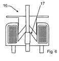
- a possible embodiment of a solenoid coil 16 with a conical face is depicted.
- the contact area where the moveable part and the resting part are facing each other, can have a conical shape. This might give a better force-distance profile, in a particular, a higher distance can be travelled with this setup.
- the length in the centre of the moving part is shorter than at the circumference. However, a design in which the centre is longer than the circumference is also possible.
Landscapes
- Push-Button Switches (AREA)
- Contacts (AREA)
Description
- The present invention relates to an electric switch for high currents, in particular with a high short circuit withstand performance in the kA-range.
- Electric switches of the aforementioned type are known from the prior art and are for example used in the public utility low voltage (LV) alternating current (AC) network provided by national electricity companies. For example, switches that contain a spring have been used, where the spring, which is mounted with the longitudinal axis of the spring parallel to the contact surface of a contact element, makes contact between two contact elements in a closed position by contacting both contact surfaces, and in which no mechanical or electrical contact exists in the open position. Switches of this type have a force profile which requires a very high compression force to prevent inadvertent opening of the contacts during high short circuit currents during a fault situation and the application of these high forces requires a larger actuator device to achieve this, if operated with an actuator device. Furthermore, such a force profile makes them difficult and unsafe to operate. For example in many switches, it is possible to move the switch from the open to a position near the closed position with negligible force, but moving into and out of the closed position requires a high force.
-
EP 0 450 104GB 2 352 879 WO 2006/027625 shows a safety switch in which a piston-shaped connection element breaks the contact if it is translationally or rotationally actuated in a cylinder. - Accordingly, the object of the present invention is to have a force profile that makes it easy and safe to operate by having a well-defined and predictable force along its travel.
- The object is achieved by an electric switch for high currents, in particular in the kA-range, comprising at least two electrically conductive contact elements, the contact elements being relatively moveable with respect to each other from an open position to a closed position while being pushed against each other by a contact force to maintain mechanical contact wherein, in the closed position, the contact elements contact each other and, in the open position, the contact elements are separated by at least one insulating element, wherein at least one contact element comprises at least one contact member that is elastically deformed under action of the contact force an wherein the contact member comprises an interior chamber in which a separate form stabilizing element is received. The present invention provides a switch for high currents as mentioned above in which the contact elements have permanent mechanical contact to each other in the closed position as well as in the open position, the necessary electrical separation in the open position being provided by at least one electrically insulating element placed between the two contact elements. Such a permanent mechanical contact gives a force profile that makes it easier and safer to operate, as the force required to move the switch from the closed to the open position is continuous and smoother, and thus well-defined and predictable for an operator.
- In the solution according to the invention, at least one contact element of a switch comprises at least one contact member that is elastically deformed under action of the contact force. This can help to hold the contact between the two contact elements, therefore improving the electrical contact between them.
- To avoid the problem of a deformation of the contact element, the contact member comprises an interior chamber in which a separate form stabilizing element can be received. In fact, to ensure tight contact, elastic deformation of the contact member may be preferred. This may be achieved with a separate form stabilizing element, which is received in the interior chamber of the contact member.
- The solution according to the invention may be combined as desired with the following further advantageous improvements.
- In a first advantageous development of the invention, the insulating element is embedded in one of the contact elements. The embedding can be such that the insulating element is permanently attached to the contact element, for example by chemically connecting the two or by gluing or soldering the two together. The embedding may also be such that the insulating element is removable from the contact element, for example by designing the outer shape of the insulating element and the contact element in a way that at least parts of the insulating element and of the contact element give a positive locking.
- In a further advantageous development an insulating surface of the insulating element is flush with a contact surface of the contact element in which the insulating element is received, the insulating surface and the contact surface both facing the other contact element. This allows for easy movement from the closed to the open position with basically a flat force profile, thus avoiding repeated compression and decompression of the spring and so reducing material fatigue to a minimum. Additionally, the ease of operation is enhanced, as no discontinuities in a direction perpendicular to the direction of travel are to be overcome when moving from the open to the closed position or vice versa, and hence the force profile is basically uniform.
- The elastic deformability of the contact member can be inherent to the material from which the contact member is made or it can be a result of the microscopic structure of the material, for example metallic sponges might be chosen. However, as most electrically conductive materials show little elasticity and creating a microscopic structure might be complicated and time consuming, the elastic deformability of the contact element is preferentially due to its shape. Several different types of spring elements might be used as contact members, preferentially those that are easy to manufacture, for example spring elements made from wire material or sheet metal.
- According to a further advantageous development of the invention, the contact member comprises a coil spring. Such a coil spring can be made from electrically conductive materials. The spring constant can be adjusted so that the contact force exerted by the spring is customized to a desired force or force profile. Soft springs with a low spring constant can be used if weak contact forces are desirable, for example if an easy movement of the contact member is necessary, stiff springs with a high spring constant can be used if a high contact force and thus a good electric contact is necessary. Coil springs with different diameters, spring constants and length are readily available with a wide choice in materials, so no extra step in manufacturing the switch is needed, which reduces the time and costs to produce the switch.
- Preferentially, the coil spring is mounted with its longitudinal axis parallel to the contact surface. This gives a high number of parallel current paths, each with the same contact area, which leads to a uniform distribution of the current through the spring and thus avoids localized high current densities, which might lead e.g. to preferential degradation of some contact areas. Furthermore, this mounting direction of the spring gives a higher contact force, which might be advantageous in most applications.
- In a preferential embodiment of the invention, the at least one coil spring is canted, i.e. sheared in the direction of the axis of the coil spring. This gives an even better force/distance characteristic when being compressed, as a canted spring can be softer in the direction perpendicular to the direction of the longitudinal axis than a regular non-canted spring, which is more or less stiff. This can help to maintain the contact if movements or vibrations occur. However, the canting is preferentially not excessive. In particular, it should be avoided that adjacent windings touch each other, as this might lead to a loss of elasticity and damage the structure, especially the contact faces. The canting can be inherent in the spring, i.e. the spring can be shaped such that the canting is already present in a relaxed, force-free state. The spring can also be canted in a biased state, e.g. if the force to shear the spring is taken up by an additional holding element. However, the shearing or canting can also only occur once a force is applied, in particular if the force has a component in the direction of the axis of the spring. Upon removal of such a force, the spring can either go back to its initial non-canted state or it can remain in an at least slightly canted state.
- In a further advantageous development of the invention, the contact element comprising the contact member is coupled to an actuator assembly. The actuator can for example be driven electrically, pneumatically, hydraulically or manually. Using an actuator enables an operator to open or close the switch from a distance. This allows for safe operation at a distance from the potentially dangerous high currents that are flowing through the switch and thus gives a higher safety for the operator. Additionally, the switch can be encased in a housing or positioned in a place where it is not accessible to the operator. Furthermore, the force exerted by the actuator can be adjusted to the switch properties by choosing different actuators and in particular the force can be much higher than the force that can be exerted by a human operator.
- The magnetic fields due to the high current flowing between the contact elements can deform the contact member to such an extent that the electrical conductivity between the contact elements is insufficient for such a high current or the contact may even be lost. Thus, welding of the contact elements to each other or arcing due to a loss or reduction of electrical contact may appear. This may damage the switch or other components in the electric circuit that can be connected to the switch. It is therefore desirable that the contact member shows little deformation when the current is flowing. This can be achieved with a contact member that has a high spring constant.
- The form stabilizing element can be either permanently attached to the contact member or be removable, for example exchangeable, so that stabilizing elements with different properties can be used for one contact member to adjust the performance of the switch to different applications. In a preferential embodiment, the shape of the form stabilising element is complementary to the outline of the interior chamber of the contact member. This ensures a tight fit of the form stabilizing element in the interior chamber of the contact member to maintain a high contact force. However, in some cases it might be advantageous if the form stabilising element is smaller than the interior chamber, e.g. if the contact member should be soft to a certain degree for small deformations, but stiff for larger deflections, or if a facile exchange is desired.
- Preferentially the form stabilizing element is made from an electrically insulating material. This has the advantage that the current path is not changed by the presence of the stabilizing element and so remains well defined and uniform, which avoids local heating, welding or arcing of the contact member due to an inhomogenous current density in the switch. In particular, the form stabilising element can be made from an elastically deformable material. This increases the contact force when the contact member is compressed and thus leads to a tight contact, but allows for small movements in the direction of compression without losing electrical contact.
- The choice of material for the form stabilising element can be guided by the requirements of the switch like the maximum allowed current or the temperature range in which it is operated. For example, it can be chosen such that it is form-stable in the operating range of the switch. Additionally, a chemically inert material is preferred, especially if the switch is located in an aggressive, e.g. a corrosive environment. In a preferred embodiment of the invention, the form stabilising element might be made from silicone-rubber. This choice ensures safe operation of the switch in the room temperature range, as this material is temperature-stable at room temperature.
- In a further advantageous development, the form stabilizing element is a cylinder. This has the advantage that forces acting upon the form stabilizing element perpendicular to its longitudinal axis do not result in a movement of the form stabilizing element. Furthermore, if the form stabilizing element is removable, the cylindrical shape allows for easy insertion and removal of the form stabilizing element into and out of the interior chamber if the chamber is accessible from the outside. Additionally, in case a uniformly wound coil spring is used, this shape returns a uniform force distribution along the longitudinal axis if the form stabilizing element is subjected to uniform external forces in a direction perpendicular to the longitudinal axis, thus avoiding higher contact forces on some parts of the contact surface. Cylindrical shapes are easy to manufacture and can for example be cut from a continuous supply, thus lowering the manufacturing costs and time. In a preferential embodiment of the invention, a cylindrical form stabilising element with a circular or oval base is received in the volume surrounded by a coil spring. This combination gives a minimum of manufacturing time and cost and a maximum of user comfort, as it allows for an easy exchange of the form stabilising element and the contact member. Especially a combination of a coil spring with a form stabilizing element that fits snugly into the coil spring is favourable, as such a tight fit ensures little movement relative to each other and thus a higher contact force is achieved and wear is minimized. However, it can be advantageous if there is only a loose fit between the form stabilizing element and the coil spring in the uncompressed state, as this allows for an easy exchange of the form stabilizing element, while the contact force enhancement is still present in the compressed state.
- In order to minimize the distance necessary to move from the open to the closed position, it is advantageous if the actuator assembly is adapted to drive a translational movement of the contact member along a direction perpendicular to the current path. In this way, quick and safe closing and opening of the switch is ensured, as the contact element has to travel only a short distance with little friction.
- In a further advantageous development, the contact member is elongated in a direction perpendicular to the current path. This elongation gives a larger contact area and thereby lowers the contact resistance as the current has many possible channels to pass in parallel. Accordingly, higher currents can be switched with such a setup. Furthermore, a large contact area, as provided by this elongation, leads to less thermal heating, resulting in a smaller temperature rise in the switch. Such an embodiment gives a well defined behaviour of the switch and reduces aging due to thermal processes.
- In a preferential embodiment, the contact element interacting with the contact member has contact areas which act as counter contacts for the contact members of the second contact element. Preferentially, these counter contacts are also elongated in a direction perpendicular to the current path and parallel to the elongation of the contact member. They may also be treated to optimize electric conductivity, for example they can be plated.
- In another advantageous development of the invention, the insulating element is elongated in a direction perpendicular to the current path. Such an elongation helps to ensure the safe opening of the switch by providing an extended rest for the contact element which tolerates deviations in the direction of the elongation. Preferentially, the elongation of the insulating element is parallel to the elongation of the contact member on a corresponding counter contact element and parallel to the elongation of the contact area. Such a configuration provides the best possible engagement between the contact member and the insulating element and the contact area. In a preferential embodiment of the invention, the insulating element is designed as a strip of homogenous width, therefore representing a counter part for the elongated contact member of a corresponding counter contact element. In an even more improved embodiment, the current path, the direction of a translational movement of an actuator assembly and the direction of the elongation of the insulation element and the contact member are mutually perpendicular to each other, i.e. they represent a three-dimensional x-y-z system. This leads to a switch with a high contact area, that is at the same time easy and safe to operate due to the minimum of travel it takes to move from the open to the closed position. Additionally, such an assembly ensures a long lifetime, as the forces that are acting are perpendicular to the structures of the switch which minimizes internal deformations.
- In an even further advantageous development, opposite ends of the contact member face the contact element. This makes it possible that the current path runs exclusively through the contact member if the contact member is embedded in a contact element made from insulating material. Such an arrangement gives a well defined current path, as the current can only flow through the contact member. It can also help to minimize the electrical resistance of a switch, as only two contacts are made, each of these contacts being enhanced by the spring force of the contact member.
- In order to further minimize the electrical resistance in the switch, the contact members and/or the contact areas can be plated e.g. with materials that have high electric conductivity and/or high hardness and/or resistance to degradation. Such a material could for example be silver, as this material has a high electric conductivity and a high resistance to oxidation, which can be a part of contact degradation.
- In a preferred embodiment of the invention a plurality of conductive and insulating strips is perpendicular to the current path. In such an arrangement, the switch can easily be opened and closed by moving a contact member along the conductive and insulating strips. With such an arrangement, it is possible to use a plurality of contact members in order to have a larger contact area. Therefore, the electric resistance of such a setup is further lowered and the temperature rise due to the resistance can be minimized. Again, the preferential configuration of a switch containing such a plurality of conductive and insulating strips is such that the movement of the contact members is perpendicular to the elongation of the conductive and insulating strips and perpendicular to the current path.
- Preferentially, the configuration of the insulating strips and the conductive strips is alternating, that means in the direction of a translation movement a conductive strip is located between two insulating strips and vice versa. The contact members of the corresponding contact element have a distance to each other that corresponds to the distance between two insulating strips. This configuration minimizes the distance necessary to move from the open position to the closed position. However, a configuration in which the insulating strips are grouped and located at a distance from the conductive strips might be preferred, as such a configuration can be safer, for example if high voltages are to be switched and a spatial separation of two conductive areas is desired. For such an application, an even simpler arrangement might be preferred, in which a plurality of contact members engages with an insulating element that has an elongation in the direction perpendicular to the current path and an elongation in the direction of the translation movement. The conductive contact areas can be located at a distance from the insulating area in the direction of the translational movement. This simple design can also help to minimize manufacturing time and costs.
- In case a plunger solenoid coil is used as an actuator, it is advantageous if the plunger has a conical face. This can be matched to a conical magnetic end-stop within the solenoid structure. Such an assembly can give a more linear force/distance characteristic than in ordinary solenoids, thus better matching the force profile of the switch and so making it possible to use smaller solenoid coils. This can be advantageous if space restrictions occur. Additionally, smaller solenoid coils might be lower in price.
- In a preferential embodiment of the invention, the current path between two first contact elements in the closed position runs through the peripheries of a plurality of contact members situated in a third contact element, which is made from an insulating material and which is relatively moveable with respect to the two first contact elements wherein the contact members are filled with insulating, form stabilizing elements and wherein the contact members protrude from two opposing sides of the third contact element, each of these sides facing one of the two first contact elements, each of which contains a plurality of conductive and insulating strips perpendicular to the current path.
- This embodiment permits safe operation of the switch by moving the third contact element between the two first contact elements in a direction perpendicular to the current path by handling the insulating part of the third contact element. Preferentially, this movement is perpendicular to the current path and to the direction of elongation of the insulating and the conductive strips. By providing several paths for the current that run parallel through the elongation of the contact members and through the several contact members, the overall electric resistance of the switch is lowered. The contact forces of the contact members can be adjusted with different contact members, for example by using coil springs of different spring constant, thickness, length and material as contact members. The performance of the contact members can further be enhanced by inserting form stabilizing elements into the contact members. Preferentially, these form stabilizing elements are made from an insulating material, for example silicone-rubber, which leaves the peripheries of the contact members as the only paths for the current. This gives a well defined behaviour of the switch, avoiding welding or arcing due to an inhomogeneous current density distribution in the switch. With such an embodiment, high contact forces are possible, thus permitting higher currents than with regular switches. As the current path is perpendicular to the contact surface of the two first contact elements and runs straight through the contact member in-between, unwanted magnetically induced mechanical forces due to high currents are minimized. This also leads to a homogenous force distribution on the contact members, and thus minimizes contact degradation.
- The invention will be described hereinafter in greater detail and in an exemplary manner using advantageous embodiments and with reference to the drawings. The described embodiments are only possible configurations in which, however, the individual features as described above can be provided independently of one another or can be omitted in the drawings:
-
- Fig. 1
- shows a schematic side view of a simple switch according to the invention;
- Fig. 2
- shows a schematic perspective view of a possible advantageous embodiment of a switch according to the invention;
- Fig. 3.
- shows a schematic perspective view of a contact member according to the invention;
- Fig. 4.
- shows a schematic sectional side view of a possible advantageous embodiment of the switch according to the invention;
- Fig. 5
- shows a schematic perspective view of another possible embodiment of a switch according to the invention.
- Fig. 6
- shows a schematic sectional side view of a solenoid coil with a conical face.
- First, the invention will be described by way of a simple example with reference to the embodiment illustrated in
Fig. 1 . - An
electric switch 1 is adapted to be connected to an electric circuit with twocontact elements contact elements - In the
contact element 2a an insulating element 3 is received, thecontact element 2b has a protrusion 19 on the electrically conductive surface 5. The switch is depicted in an electrically open position, as the protrusion 4 of thecontact element 2b rests on an insulating element 3 of thecontact element 2a. InFig. 1 the protrusion 4 is shown to be a part of thecontact element 2a, in fact, the protrusion 4 may be a separate component. Although the switch is electrically open, thecontact elements switch 1 can be brought into an electrically closed position by moving one of thecontact elements other contact element contact elements - The insulating element 3 can be permanently attached to the
contact element 2a for example by gluing, soldering, welding or by a chemical connection between thecontact element 2a and the insulating element 3. The insulating element 3 may also be attached removeably to thecontact element 2a, for example by designing the shape of the insulating element 3 and thecontact element 2a such that they are complementary and engage in a form fit. - Preferably, the surface of the insulating element 3 is flush with the surface of the
contact element 2a. This minimises the force required to move theswitch 1 from the open to the closed position. However, for example if a haptic feedback for the operator is desired, discontinuities in the direction perpendicular to the direction of travel might be preferred. -
Fig. 2 andFig. 4 show another embodiment of the invention. Theelectric switch 1 consists of threecontact elements contact element 2b is not shown inFig. 2 , so that thecontact element 2c can be seen. The contact surfaces 5a, 5b of thecontact elements contact elements contact elements contact elements contact elements - A
third contact element 2c is located between thecontact elements contact elements third contact element 2c can contain an insulating material with one or more, in the example ofFig. 2 , two, cut out portions into which electricallyconductive contact members 6 may be inserted. These cut out portions can, for example, be slit-like. In this preferential embodiment, thecontact members 6 are made up of coil springs 7, theinterior chamber 8 of these being filled with a form stabilising element 9, in the shape of a cylinder 10. - In a preferential embodiment of the invention, the coil springs 7 are canted, that means they are sheared in the direction of the longitudinal axis of the spring, but the inclined windings of the spring should not touch each other. Canted springs are more elastic in the direction of the current path than a basically stiff non-canted spring. However, excessive canting should be avoided. In particular, the windings or turns should not touch each other, as the compressibility will be lost, which can possibly lead to a damaging of the structure. The canting may be inherent to the spring or can be caused by forces acting upon it
- The
third contact element 2c may be translationally moved in the direction M, either manually or by means of an actuator assembly 11 (not shown). This makes or breaks the electric conduction between thecontact elements contact element 2c rest upon the insulating elements 3 of thecontact elements contact elements contact member 6 is elastically deformable, it generates a force F necessary to maintain mechanical contact between thecontact elements - According to
Fig. 2 andFig. 4 , a plurality of conductive and insulating areas on thecontact elements switch 1, in particular to the maximum current that can flow through the switch. For example, a higher number of contact members can be used, if more current is supposed to flow. - The surfaces of the insulating elements 3 can be flush with the rest of the surface of the
contact element third contact element 2c with respect to the twofirst contact elements - The pluralities of conductive and insulating strips in
Fig. 2 andFig. 4 are arranged such that the insulating strips 12 and the conductive strips 13 are alternating, that means an insulating strip 12 is located between two conductive strips 13 and vice versa. The elongation of the insulating strips 12 and the conductive strips 13 is parallel to the elongation of thecontact member 6 of thethird contact element 2c, which ensures proper engagement of the coil springs 7 of thethird contact element 2c with the insulating strips 12 and the conductive strips 13, respectively, of thecontact elements - The coil springs 7 that are used as
contact members 6 in thecontact element 2c can preferentially have uniform windings, so that the force they exert on thecontact elements - A configuration of a
switch 1 as depicted inFig. 2 orFig. 4 provides a current path I that enters and exits the contact surfaces 5 of the conductive strips 13 of thecontact elements contact elements third contact element 2c by these induced mechanical forces is minimised. - Additionally, a
switch 1, which is designed as depicted inFig. 2 with twocontact elements contact members 6 and the conductive strips 13 and hence minimizes contact degradation due to a varying force profile along the elongation of thecontact members 6 and the conductive strips 13. - The
contact element 2c can be adapted to be driven by an actuator assembly 11 for example electrically, mechanically, pneumatically or manually. The direction of the movement M is preferentially linear in this configuration. However, the design of theswitch 1 can be such that a rotational movement of one contact element 2 is favourable, for example the contact element 2 might be designed in a disc-like shape. - The actuator assembly 11 can be adapted to the properties of the
switch 1, in particular to the contact force F exerted by thecontact members 6. The force F exerted by the actuator assembly 11 can exceed the force that can be exerted by a human operator. - Using an actuator assembly 11 can be advantageous, as it allows the operator to operate the
switch 1 at a distance, which makes the operation of theswitch 1 safer as potentially dangerous and harmful currents can flow through theswitch 1. Additionally, theswitch 1 can be located in a housing or in a position far away from the operator. -
Fig. 3 shows a possible embodiment of acontact member 6 of aswitch 1 according to the invention. In this case, thecontact member 6 is embodied as a coil spring 7. The volume surrounded by the inner contour of the coil spring 7 represents theinterior chamber 8 into which the outer contour of a form stabilising element 9 can be inserted. In this embodiment, the form stabilising element 9 is a cylinder 10 with a circular or oval base. This helps to minimise the extent to which thecontact member 6 is deformed in the direction of the force F acting perpendicular to the axis of the coil spring 7. - The material of the form stabilising element 9 can be chosen from a variety of materials. For example the form stabilising element 9 may be conductive or non-conductive, or it can be stiff or soft. Additionally, the material may be chosen such that other properties of the material are advantageous for the purpose of the
switch 1. It can for example be advantageous in some applications if the material is form-stable in the temperature range of operation of theswitch 1. Preferentially, silicone-rubber is used as a material for the form stabilizing element. - In this embodiment, the form stabilising element 9 is designed to fit snugly into the coil spring 7, thus providing little space for movement of the two with respect to the other which increases contact force. In case the coil spring 7 is mounted with the longitudinal axis parallel to the contact surface 5 of the contact element 2, it is advantageous if a spring with many windings is used. This provides many possible current paths in parallel and thus gives a low overall electric resistance of the
contact member 6 and theswitch 1. - In
Fig. 4 , a sectional side view of aswitch 1 similar to the configuration shown inFig. 2 is depicted. In this embodiment, the number ofcontact members 6 and insulating elements 3 and conductive contact surfaces 5 of thecontact elements - The
switch 1 is shown in an electrically closed position in which a current can flow along the current path I fromcontact element 2a viacontact element 2c to contactelement 2b, where the current can flow exclusively through thecontact member 6, embodied as a coil spring 7, as the other parts of thecontact element 2c are made from an insulating material. In particular, the form stabilising element 9 which is cylindrical also consists of an insulating material, for example silicone-rubber. The windings of the coil spring 7 are the only paths for the current. This gives a well defined current path I and avoids localized high current densities in parts of theswitch 1. High current densities, which might cause arcing, welding or contact degradation are avoided. - By choosing a coil spring 7 with a constant winding density as a
contact member 6 and a uniformly distributed contact force F, the distribution of the current density is also uniform along the contact surface 5 of thecontact member 6. This avoids an inhomogeneous current distribution along the contact surface 5 and hence minimises the temperature rise and avoids arcing and welding, which might occur due to localised high current densities and lead to contact degradation. - In order to open or close the switch, the
contact element 2c can be moved along the direction M, which positions thecontact member 6 of thecontact element 2c either in electric contact with each of thecontact elements contact elements contact element 2c, each of thecontact elements contact element 2c, which gives a well-defined and predictable force profile when moving from the open to the closed position, improving the ease of use of theswitch 1 for the operator. - The fact that the current flows from
contact element 2a to contactelement 2b along a very short path, which is perpendicular to the contact surfaces 5 of the contact elements 2, minimises unwanted magnetically induced mechanical forces, in particular if high currents are flowing. - In
Fig. 5 another possible embodiment of aswitch 1 according to the invention is schematically depicted. Each of thecontact elements supports bushings 15. The twocontact elements contact elements contact elements third contact element 2c is located. Thisthird contact element 2c is connected to a solenoid coil that can move thethird contact element 2c. The contact element may have elongated cut out portions which provide space forcontact members 6. The actuator assembly 11, embodied as an electrically drivensolenoid coil 16, can move thethird contact element 2c translationally and in a direction M perpendicular to the elongation of the conductive strips 13 and the insulating strips 12 and perpendicular to the current path I. This makes or breaks the electric conductivity betweencontact element contact members 6 located in thethird contact element 2c from a position where they rest on the insulating strips 12 to a position where they rest on the conductive strips 13 or vice versa, respectively. - The
actuator assembly 6, which is electrically driven, is located away from the area of strong magnetic fields induced by the high currents that are flowing in theswitch 1. This prevents faulty operation of the electrically driven actuator assembly 11 which might be caused by induced currents. - In
Fig. 6 , a possible embodiment of asolenoid coil 16 with a conical face is depicted. Unlike in usual solenoid coils, the contact area, where the moveable part and the resting part are facing each other, can have a conical shape. This might give a better force-distance profile, in a particular, a higher distance can be travelled with this setup. In the setup shown inFig. 6 , the length in the centre of the moving part is shorter than at the circumference. However, a design in which the centre is longer than the circumference is also possible.
Claims (13)
- Electric switch (1) for high currents, in particular in the kA-range, comprising at least two electrically conductive contact elements (2), the contact elements (2) being relatively moveable with respect to each other from an open position to a closed position while being pushed against each other by a contact force (F) to maintain mechanical contact wherein, in the closed position, the contact elements (2) contact each other and, in the open position, the contact elements (2) are separated by at least one insulating element (3), characterised in that at least one contact element (2) comprises at least one contact member (6) that is elastically deformed under action of the contact force (F) and wherein the contact member (6) comprises an interior chamber (8) in which a separate form stabilizing element (9) is received.
- Electric switch (1) according to claim 1, wherein the insulating element (3) is embedded in one of the contact elements (2).
- Electric switch (1) according to claim 1 or 2, wherein an insulating surface of the insulating element (3) is flush with a contact surface (5) of the contact element (2), in which the insulating element (3) is received, the insulating surface and the contact surface (5) both facing the other contact element (2).
- Electric switch (1) according to one of claims 1 to 3, wherein the contact element (2) comprising the contact member (6) is coupled to an actuator assembly (11).
- Electric switch (1) according to one of claims 1 to 4, wherein the form stabilising element (9) is made from an electrically insulating material, for example silicone-rubber.
- Electric switch (1) according to one of claims 1 to 5, wherein the form stabilising element (9) is a cylinder (10).
- Electric switch (1) according to one of claims 4 to 6, wherein the actuator assembly (11) is adapted to drive a translational movement of the contact member along a direction perpendicular to the current path.
- Electric switch (1) according to one of claims 1 to 7, wherein the contact member (6) is elongated in a direction perpendicular to the current path.
- Electric switch (1) according to one of claims 1 to 8, wherein the insulating element (3) is elongated in a direction perpendicular to the current path.
- Electric switch (1) according to one of claims 1 to 9, wherein opposite ends of the contact member face a contact element (2).
- Electric switch (1) according to one of claims 1 to 10, wherein a plurality of conductive strips (13) and insulating strips (12) is perpendicular to the current path.
- Electric switch (1) according to one of claims 4 to 11, wherein the actuator assembly (11) contains a plunger solenoid coil (16) with a conical face (17).
- Electric switch (1) according to claims 4 to 12, wherein the current path between two first contact elements (2a, 2b) in the closed position runs through the peripheries of a plurality of contact members (6) situated in a third contact element (2c), which is made from an insulating material and which is relatively moveable with respect to the two first contact elements (2a, 2b), wherein the contact members are filled with insulating, form stabilising elements (9) and wherein the contact member (6) protrudes from two opposing sides of the third contact element (2c), each of these sides facing one of the two first contact elements (2a, 2b), each of which contains a plurality of conductive strips (13) and insulating strips (12) perpendicular to the current path.
Priority Applications (3)
| Application Number | Priority Date | Filing Date | Title |
|---|---|---|---|
| EP11171944.9A EP2541570B1 (en) | 2011-06-29 | 2011-06-29 | Electric switch for high currents, in particular with a high short circuit withstand performance in the kA-range |
| PCT/EP2012/062640 WO2013001039A1 (en) | 2011-06-29 | 2012-06-28 | Electric switch for high currents, in particular with a high short circuit withstand performance in the ka-range |
| US14/141,911 US9673003B2 (en) | 2011-06-29 | 2013-12-27 | Electric switch for high currents, in particular with a high short circuit withstand performance in the KA-range |
Applications Claiming Priority (1)
| Application Number | Priority Date | Filing Date | Title |
|---|---|---|---|
| EP11171944.9A EP2541570B1 (en) | 2011-06-29 | 2011-06-29 | Electric switch for high currents, in particular with a high short circuit withstand performance in the kA-range |
Publications (2)
| Publication Number | Publication Date |
|---|---|
| EP2541570A1 EP2541570A1 (en) | 2013-01-02 |
| EP2541570B1 true EP2541570B1 (en) | 2014-12-24 |
Family
ID=44951538
Family Applications (1)
| Application Number | Title | Priority Date | Filing Date |
|---|---|---|---|
| EP11171944.9A Active EP2541570B1 (en) | 2011-06-29 | 2011-06-29 | Electric switch for high currents, in particular with a high short circuit withstand performance in the kA-range |
Country Status (3)
| Country | Link |
|---|---|
| US (1) | US9673003B2 (en) |
| EP (1) | EP2541570B1 (en) |
| WO (1) | WO2013001039A1 (en) |
Families Citing this family (1)
| Publication number | Priority date | Publication date | Assignee | Title |
|---|---|---|---|---|
| CN106765390B (en) * | 2016-12-21 | 2023-06-30 | 中山市甜美电器有限公司 | Concealed lifting smoke extractor |
Family Cites Families (10)
| Publication number | Priority date | Publication date | Assignee | Title |
|---|---|---|---|---|
| US2156902A (en) * | 1935-09-09 | 1939-05-02 | Mc Gill Mfg Co | Electric switch |
| JPS61151214U (en) * | 1985-03-09 | 1986-09-18 | ||
| DE59009511D1 (en) * | 1990-03-28 | 1995-09-14 | Siemens Ag | Quick switch. |
| JP3834862B2 (en) * | 1996-03-07 | 2006-10-18 | 住友電気工業株式会社 | Mechanical electrical switch element |
| WO2001009908A1 (en) * | 1999-07-30 | 2001-02-08 | W.W. Grew & Company Limited | Electrical circuit breakers |
| US7055812B2 (en) * | 2002-09-30 | 2006-06-06 | Bal Seal Engineering Co., Inc. | Canted coil springs various designs |
| GB0420049D0 (en) * | 2004-09-10 | 2004-10-13 | Aea Technology Battery Systems | Safety switch |
| JP2007026940A (en) * | 2005-07-19 | 2007-02-01 | Tokai Rika Co Ltd | Switch device |
| JP5111623B2 (en) * | 2009-02-13 | 2013-01-09 | 三菱電機株式会社 | Contact device |
| FR2953324B1 (en) * | 2009-11-27 | 2012-06-08 | Snpe Materiaux Energetiques | ELECTRIC SWITCH WITH SLIDING DRAWER FORMING CIRCUIT BREAKER OR SWITCH |
-
2011
- 2011-06-29 EP EP11171944.9A patent/EP2541570B1/en active Active
-
2012
- 2012-06-28 WO PCT/EP2012/062640 patent/WO2013001039A1/en not_active Ceased
-
2013
- 2013-12-27 US US14/141,911 patent/US9673003B2/en active Active
Also Published As
| Publication number | Publication date |
|---|---|
| US9673003B2 (en) | 2017-06-06 |
| EP2541570A1 (en) | 2013-01-02 |
| WO2013001039A1 (en) | 2013-01-03 |
| US20140110377A1 (en) | 2014-04-24 |
Similar Documents
| Publication | Publication Date | Title |
|---|---|---|
| US9027903B2 (en) | Power-efficient actuator assemblies and methods of manufacture | |
| CN102881472B (en) | There is the high-speed switch of non-circular thomson coil | |
| WO2005008703A1 (en) | Multiple-contact woven electrical switches | |
| EP3929958A1 (en) | Relay | |
| KR20250039894A (en) | Relay | |
| CN107492467B (en) | Medium voltage contactor | |
| EP2541570A1 (en) | Electric switch for high currents, in particular with a high short circuit withstand performance in the kA-range | |
| CN113228217B (en) | Medium voltage switch pole | |
| CN110945618B (en) | Armature for electromagnetic actuator, electromagnetic actuator, switching device and method for manufacturing armature | |
| KR100990267B1 (en) | Magnetic contactor with wear protection means | |
| CN108695114A (en) | Relay and its contact system | |
| US11527375B2 (en) | Relay contactor with combined linear and rotation motion | |
| CN221596301U (en) | Extraction structure and magnetic latching relay | |
| BR102012020695A2 (en) | Meter and System Disconnect Relay | |
| CN212062322U (en) | High-current-carrying movable contact spring of electromagnetic relay capable of avoiding abrupt increase of counter force | |
| CN102473535B (en) | For the contact making device of electromagnetic switchgear | |
| CN117174534A (en) | Lead-out structure and magnetic latching relay | |
| CN210325649U (en) | Contact device and contactor with same | |
| WO2009042306A1 (en) | Shape memory alloy and actuator | |
| CN106876173B (en) | Electric switch and method | |
| EP3078043B1 (en) | Contact arrangement for high power relay | |
| CN110690064B (en) | A load switch | |
| CN107851531A (en) | switch | |
| JP2021118183A (en) | Electromagnetic actuator, and electrical switching unit including electromagnetic actuator of this kind | |
| EP4597530A1 (en) | Contact bridge assembly and electrical switching device |
Legal Events
| Date | Code | Title | Description |
|---|---|---|---|
| PUAI | Public reference made under article 153(3) epc to a published international application that has entered the european phase |
Free format text: ORIGINAL CODE: 0009012 |
|
| AK | Designated contracting states |
Kind code of ref document: A1 Designated state(s): AL AT BE BG CH CY CZ DE DK EE ES FI FR GB GR HR HU IE IS IT LI LT LU LV MC MK MT NL NO PL PT RO RS SE SI SK SM TR |
|
| AX | Request for extension of the european patent |
Extension state: BA ME |
|
| 17P | Request for examination filed |
Effective date: 20130626 |
|
| RBV | Designated contracting states (corrected) |
Designated state(s): AL AT BE BG CH CY CZ DE DK EE ES FI FR GB GR HR HU IE IS IT LI LT LU LV MC MK MT NL NO PL PT RO RS SE SI SK SM TR |
|
| GRAP | Despatch of communication of intention to grant a patent |
Free format text: ORIGINAL CODE: EPIDOSNIGR1 |
|
| INTG | Intention to grant announced |
Effective date: 20140716 |
|
| RAP1 | Party data changed (applicant data changed or rights of an application transferred) |
Owner name: RAYCHEM INTERNATIONAL Owner name: TYCO ELECTRONICS UK LTD. |
|
| GRAS | Grant fee paid |
Free format text: ORIGINAL CODE: EPIDOSNIGR3 |
|
| GRAA | (expected) grant |
Free format text: ORIGINAL CODE: 0009210 |
|
| AK | Designated contracting states |
Kind code of ref document: B1 Designated state(s): AL AT BE BG CH CY CZ DE DK EE ES FI FR GB GR HR HU IE IS IT LI LT LU LV MC MK MT NL NO PL PT RO RS SE SI SK SM TR |
|
| REG | Reference to a national code |
Ref country code: GB Ref legal event code: FG4D |
|
| REG | Reference to a national code |
Ref country code: CH Ref legal event code: EP |
|
| REG | Reference to a national code |
Ref country code: IE Ref legal event code: FG4D |
|
| REG | Reference to a national code |
Ref country code: AT Ref legal event code: REF Ref document number: 703507 Country of ref document: AT Kind code of ref document: T Effective date: 20150115 |
|
| REG | Reference to a national code |
Ref country code: DE Ref legal event code: R096 Ref document number: 602011012475 Country of ref document: DE Effective date: 20150212 |
|
| REG | Reference to a national code |
Ref country code: NL Ref legal event code: VDEP Effective date: 20141224 |
|
| PG25 | Lapsed in a contracting state [announced via postgrant information from national office to epo] |
Ref country code: FI Free format text: LAPSE BECAUSE OF FAILURE TO SUBMIT A TRANSLATION OF THE DESCRIPTION OR TO PAY THE FEE WITHIN THE PRESCRIBED TIME-LIMIT Effective date: 20141224 Ref country code: LT Free format text: LAPSE BECAUSE OF FAILURE TO SUBMIT A TRANSLATION OF THE DESCRIPTION OR TO PAY THE FEE WITHIN THE PRESCRIBED TIME-LIMIT Effective date: 20141224 Ref country code: NO Free format text: LAPSE BECAUSE OF FAILURE TO SUBMIT A TRANSLATION OF THE DESCRIPTION OR TO PAY THE FEE WITHIN THE PRESCRIBED TIME-LIMIT Effective date: 20150324 |
|
| REG | Reference to a national code |
Ref country code: LT Ref legal event code: MG4D |
|
| PG25 | Lapsed in a contracting state [announced via postgrant information from national office to epo] |
Ref country code: LV Free format text: LAPSE BECAUSE OF FAILURE TO SUBMIT A TRANSLATION OF THE DESCRIPTION OR TO PAY THE FEE WITHIN THE PRESCRIBED TIME-LIMIT Effective date: 20141224 Ref country code: SE Free format text: LAPSE BECAUSE OF FAILURE TO SUBMIT A TRANSLATION OF THE DESCRIPTION OR TO PAY THE FEE WITHIN THE PRESCRIBED TIME-LIMIT Effective date: 20141224 Ref country code: HR Free format text: LAPSE BECAUSE OF FAILURE TO SUBMIT A TRANSLATION OF THE DESCRIPTION OR TO PAY THE FEE WITHIN THE PRESCRIBED TIME-LIMIT Effective date: 20141224 Ref country code: RS Free format text: LAPSE BECAUSE OF FAILURE TO SUBMIT A TRANSLATION OF THE DESCRIPTION OR TO PAY THE FEE WITHIN THE PRESCRIBED TIME-LIMIT Effective date: 20141224 Ref country code: GR Free format text: LAPSE BECAUSE OF FAILURE TO SUBMIT A TRANSLATION OF THE DESCRIPTION OR TO PAY THE FEE WITHIN THE PRESCRIBED TIME-LIMIT Effective date: 20150325 |
|
| REG | Reference to a national code |
Ref country code: AT Ref legal event code: MK05 Ref document number: 703507 Country of ref document: AT Kind code of ref document: T Effective date: 20141224 |
|
| PG25 | Lapsed in a contracting state [announced via postgrant information from national office to epo] |
Ref country code: NL Free format text: LAPSE BECAUSE OF FAILURE TO SUBMIT A TRANSLATION OF THE DESCRIPTION OR TO PAY THE FEE WITHIN THE PRESCRIBED TIME-LIMIT Effective date: 20141224 |
|
| PG25 | Lapsed in a contracting state [announced via postgrant information from national office to epo] |
Ref country code: EE Free format text: LAPSE BECAUSE OF FAILURE TO SUBMIT A TRANSLATION OF THE DESCRIPTION OR TO PAY THE FEE WITHIN THE PRESCRIBED TIME-LIMIT Effective date: 20141224 Ref country code: RO Free format text: LAPSE BECAUSE OF FAILURE TO SUBMIT A TRANSLATION OF THE DESCRIPTION OR TO PAY THE FEE WITHIN THE PRESCRIBED TIME-LIMIT Effective date: 20141224 Ref country code: ES Free format text: LAPSE BECAUSE OF FAILURE TO SUBMIT A TRANSLATION OF THE DESCRIPTION OR TO PAY THE FEE WITHIN THE PRESCRIBED TIME-LIMIT Effective date: 20141224 Ref country code: SK Free format text: LAPSE BECAUSE OF FAILURE TO SUBMIT A TRANSLATION OF THE DESCRIPTION OR TO PAY THE FEE WITHIN THE PRESCRIBED TIME-LIMIT Effective date: 20141224 Ref country code: CZ Free format text: LAPSE BECAUSE OF FAILURE TO SUBMIT A TRANSLATION OF THE DESCRIPTION OR TO PAY THE FEE WITHIN THE PRESCRIBED TIME-LIMIT Effective date: 20141224 |
|
| PG25 | Lapsed in a contracting state [announced via postgrant information from national office to epo] |
Ref country code: IS Free format text: LAPSE BECAUSE OF FAILURE TO SUBMIT A TRANSLATION OF THE DESCRIPTION OR TO PAY THE FEE WITHIN THE PRESCRIBED TIME-LIMIT Effective date: 20150424 Ref country code: AT Free format text: LAPSE BECAUSE OF FAILURE TO SUBMIT A TRANSLATION OF THE DESCRIPTION OR TO PAY THE FEE WITHIN THE PRESCRIBED TIME-LIMIT Effective date: 20141224 Ref country code: PL Free format text: LAPSE BECAUSE OF FAILURE TO SUBMIT A TRANSLATION OF THE DESCRIPTION OR TO PAY THE FEE WITHIN THE PRESCRIBED TIME-LIMIT Effective date: 20141224 |
|
| REG | Reference to a national code |
Ref country code: DE Ref legal event code: R097 Ref document number: 602011012475 Country of ref document: DE |
|
| PG25 | Lapsed in a contracting state [announced via postgrant information from national office to epo] |
Ref country code: DK Free format text: LAPSE BECAUSE OF FAILURE TO SUBMIT A TRANSLATION OF THE DESCRIPTION OR TO PAY THE FEE WITHIN THE PRESCRIBED TIME-LIMIT Effective date: 20141224 |
|
| PLBE | No opposition filed within time limit |
Free format text: ORIGINAL CODE: 0009261 |
|
| STAA | Information on the status of an ep patent application or granted ep patent |
Free format text: STATUS: NO OPPOSITION FILED WITHIN TIME LIMIT |
|
| 26N | No opposition filed |
Effective date: 20150925 |
|
| PG25 | Lapsed in a contracting state [announced via postgrant information from national office to epo] |
Ref country code: IT Free format text: LAPSE BECAUSE OF FAILURE TO SUBMIT A TRANSLATION OF THE DESCRIPTION OR TO PAY THE FEE WITHIN THE PRESCRIBED TIME-LIMIT Effective date: 20141224 |
|
| PG25 | Lapsed in a contracting state [announced via postgrant information from national office to epo] |
Ref country code: MC Free format text: LAPSE BECAUSE OF FAILURE TO SUBMIT A TRANSLATION OF THE DESCRIPTION OR TO PAY THE FEE WITHIN THE PRESCRIBED TIME-LIMIT Effective date: 20141224 |
|
| REG | Reference to a national code |
Ref country code: CH Ref legal event code: PL |
|
| PG25 | Lapsed in a contracting state [announced via postgrant information from national office to epo] |
Ref country code: LU Free format text: LAPSE BECAUSE OF FAILURE TO SUBMIT A TRANSLATION OF THE DESCRIPTION OR TO PAY THE FEE WITHIN THE PRESCRIBED TIME-LIMIT Effective date: 20150629 Ref country code: SI Free format text: LAPSE BECAUSE OF FAILURE TO SUBMIT A TRANSLATION OF THE DESCRIPTION OR TO PAY THE FEE WITHIN THE PRESCRIBED TIME-LIMIT Effective date: 20141224 |
|
| REG | Reference to a national code |
Ref country code: IE Ref legal event code: MM4A |
|
| PG25 | Lapsed in a contracting state [announced via postgrant information from national office to epo] |
Ref country code: IE Free format text: LAPSE BECAUSE OF NON-PAYMENT OF DUE FEES Effective date: 20150629 Ref country code: CH Free format text: LAPSE BECAUSE OF NON-PAYMENT OF DUE FEES Effective date: 20150630 Ref country code: LI Free format text: LAPSE BECAUSE OF NON-PAYMENT OF DUE FEES Effective date: 20150630 |
|
| PG25 | Lapsed in a contracting state [announced via postgrant information from national office to epo] |
Ref country code: BE Free format text: LAPSE BECAUSE OF FAILURE TO SUBMIT A TRANSLATION OF THE DESCRIPTION OR TO PAY THE FEE WITHIN THE PRESCRIBED TIME-LIMIT Effective date: 20141224 |
|
| REG | Reference to a national code |
Ref country code: FR Ref legal event code: PLFP Year of fee payment: 6 |
|
| PG25 | Lapsed in a contracting state [announced via postgrant information from national office to epo] |
Ref country code: MT Free format text: LAPSE BECAUSE OF FAILURE TO SUBMIT A TRANSLATION OF THE DESCRIPTION OR TO PAY THE FEE WITHIN THE PRESCRIBED TIME-LIMIT Effective date: 20141224 |
|
| PG25 | Lapsed in a contracting state [announced via postgrant information from national office to epo] |
Ref country code: SM Free format text: LAPSE BECAUSE OF FAILURE TO SUBMIT A TRANSLATION OF THE DESCRIPTION OR TO PAY THE FEE WITHIN THE PRESCRIBED TIME-LIMIT Effective date: 20141224 Ref country code: BG Free format text: LAPSE BECAUSE OF FAILURE TO SUBMIT A TRANSLATION OF THE DESCRIPTION OR TO PAY THE FEE WITHIN THE PRESCRIBED TIME-LIMIT Effective date: 20141224 Ref country code: HU Free format text: LAPSE BECAUSE OF FAILURE TO SUBMIT A TRANSLATION OF THE DESCRIPTION OR TO PAY THE FEE WITHIN THE PRESCRIBED TIME-LIMIT; INVALID AB INITIO Effective date: 20110629 |
|
| REG | Reference to a national code |
Ref country code: FR Ref legal event code: PLFP Year of fee payment: 7 |
|
| PG25 | Lapsed in a contracting state [announced via postgrant information from national office to epo] |
Ref country code: CY Free format text: LAPSE BECAUSE OF FAILURE TO SUBMIT A TRANSLATION OF THE DESCRIPTION OR TO PAY THE FEE WITHIN THE PRESCRIBED TIME-LIMIT Effective date: 20141224 |
|
| PG25 | Lapsed in a contracting state [announced via postgrant information from national office to epo] |
Ref country code: TR Free format text: LAPSE BECAUSE OF FAILURE TO SUBMIT A TRANSLATION OF THE DESCRIPTION OR TO PAY THE FEE WITHIN THE PRESCRIBED TIME-LIMIT Effective date: 20141224 |
|
| REG | Reference to a national code |
Ref country code: FR Ref legal event code: PLFP Year of fee payment: 8 |
|
| PG25 | Lapsed in a contracting state [announced via postgrant information from national office to epo] |
Ref country code: MK Free format text: LAPSE BECAUSE OF FAILURE TO SUBMIT A TRANSLATION OF THE DESCRIPTION OR TO PAY THE FEE WITHIN THE PRESCRIBED TIME-LIMIT Effective date: 20141224 |
|
| PG25 | Lapsed in a contracting state [announced via postgrant information from national office to epo] |
Ref country code: PT Free format text: LAPSE BECAUSE OF FAILURE TO SUBMIT A TRANSLATION OF THE DESCRIPTION OR TO PAY THE FEE WITHIN THE PRESCRIBED TIME-LIMIT Effective date: 20141224 |
|
| REG | Reference to a national code |
Ref country code: DE Ref legal event code: R082 Ref document number: 602011012475 Country of ref document: DE Representative=s name: GRUENECKER PATENT- UND RECHTSANWAELTE PARTG MB, DE Ref country code: DE Ref legal event code: R081 Ref document number: 602011012475 Country of ref document: DE Owner name: EA TECHNOLOGY LTD., GB Free format text: FORMER OWNERS: RAYCHEM INTERNATIONAL, SHANNON, CO. CLARE, IE; TYCO ELECTRONICS UK LTD., SWINDON, WILTSHIRE, GB |
|
| REG | Reference to a national code |
Ref country code: GB Ref legal event code: 732E Free format text: REGISTERED BETWEEN 20180823 AND 20180829 |
|
| REG | Reference to a national code |
Ref country code: GB Ref legal event code: 732E Free format text: REGISTERED BETWEEN 20180830 AND 20180905 |
|
| PG25 | Lapsed in a contracting state [announced via postgrant information from national office to epo] |
Ref country code: AL Free format text: LAPSE BECAUSE OF FAILURE TO SUBMIT A TRANSLATION OF THE DESCRIPTION OR TO PAY THE FEE WITHIN THE PRESCRIBED TIME-LIMIT Effective date: 20141224 |
|
| PGFP | Annual fee paid to national office [announced via postgrant information from national office to epo] |
Ref country code: GB Payment date: 20250619 Year of fee payment: 15 |
|
| PGFP | Annual fee paid to national office [announced via postgrant information from national office to epo] |
Ref country code: FR Payment date: 20250627 Year of fee payment: 15 |
|
| PGFP | Annual fee paid to national office [announced via postgrant information from national office to epo] |
Ref country code: DE Payment date: 20250630 Year of fee payment: 15 |