EP2541460A1 - Electronic device for prevention of data leakage via a removable storage medium - Google Patents
Electronic device for prevention of data leakage via a removable storage medium Download PDFInfo
- Publication number
- EP2541460A1 EP2541460A1 EP12174011A EP12174011A EP2541460A1 EP 2541460 A1 EP2541460 A1 EP 2541460A1 EP 12174011 A EP12174011 A EP 12174011A EP 12174011 A EP12174011 A EP 12174011A EP 2541460 A1 EP2541460 A1 EP 2541460A1
- Authority
- EP
- European Patent Office
- Prior art keywords
- storage medium
- encryption key
- usb memory
- user
- cpu
- Prior art date
- Legal status (The legal status is an assumption and is not a legal conclusion. Google has not performed a legal analysis and makes no representation as to the accuracy of the status listed.)
- Granted
Links
Images



Classifications
-
- G—PHYSICS
- G06—COMPUTING OR CALCULATING; COUNTING
- G06F—ELECTRIC DIGITAL DATA PROCESSING
- G06F21/00—Security arrangements for protecting computers, components thereof, programs or data against unauthorised activity
- G06F21/70—Protecting specific internal or peripheral components, in which the protection of a component leads to protection of the entire computer
- G06F21/78—Protecting specific internal or peripheral components, in which the protection of a component leads to protection of the entire computer to assure secure storage of data
- G06F21/79—Protecting specific internal or peripheral components, in which the protection of a component leads to protection of the entire computer to assure secure storage of data in semiconductor storage media, e.g. directly-addressable memories
-
- G—PHYSICS
- G06—COMPUTING OR CALCULATING; COUNTING
- G06F—ELECTRIC DIGITAL DATA PROCESSING
- G06F12/00—Accessing, addressing or allocating within memory systems or architectures
- G06F12/14—Protection against unauthorised use of memory or access to memory
-
- G—PHYSICS
- G06—COMPUTING OR CALCULATING; COUNTING
- G06F—ELECTRIC DIGITAL DATA PROCESSING
- G06F12/00—Accessing, addressing or allocating within memory systems or architectures
- G06F12/14—Protection against unauthorised use of memory or access to memory
- G06F12/1408—Protection against unauthorised use of memory or access to memory by using cryptography
-
- G—PHYSICS
- G06—COMPUTING OR CALCULATING; COUNTING
- G06F—ELECTRIC DIGITAL DATA PROCESSING
- G06F15/00—Digital computers in general; Data processing equipment in general
- G06F15/16—Combinations of two or more digital computers each having at least an arithmetic unit, a program unit and a register, e.g. for a simultaneous processing of several programs
- G06F15/163—Interprocessor communication
- G06F15/167—Interprocessor communication using a common memory, e.g. mailbox
-
- G—PHYSICS
- G06—COMPUTING OR CALCULATING; COUNTING
- G06F—ELECTRIC DIGITAL DATA PROCESSING
- G06F21/00—Security arrangements for protecting computers, components thereof, programs or data against unauthorised activity
- G06F21/60—Protecting data
Definitions
- the present disclosure relates to an electronic device causing a removable storage medium to store data.
- a removable storage medium such as a USB (Universal Serial Bus) memory or an SD (Secure Digital) card
- USB Universal Serial Bus
- SD Secure Digital
- the leaving removable medium mounted on the device has been recognized as a problem to be solved from the viewpoint of security, and some techniques for preventing the leaving have been developed. However, such techniques are only to prevent the leaving itself, and fail to describe how to prevent information leakage when the leaving actually occurs.
- a method of preventing information leakage through encryption of image (data) and storing of the encrypted image in the removable medium may be considered.
- pre-registration of an encryption key is necessary. Otherwise, there are issues such as only being able to decrypt the image on a specific PC, which cause inconvenience.
- the present disclosure has been made to solve the above-mentioned problems occurring in the related art, and an object of the disclosure is to prevent the information leakage due to the leaving the removable storage medium mounted on or connected to the device while ensuring convenience for the user.
- an electronic device which includes a removable storage medium; a storage medium interface connecting to the storage medium; and a control unit generating an encryption key at a predetermined timing, encrypting data to be stored in the storage medium using the encryption key, storing the encrypted data in the storage medium, and storing the encryption key in the storage medium in association with the encrypted data if it is detected that a removal operation of the storage medium has been made by a user.
- the storage medium be set to a removable state, and if a timeout of an automatic logout function occurs in a state where no operation is made by the user for a predetermined time, restore a connection state between the storage medium interface and the storage medium again to delete the encryption key from the storage medium.
- the control unit after the control unit has stored the encryption key in the storage medium when detecting that a logout button is pressed as the removal operation of the storage medium by the user, start a timer after setting the storage medium in a removable state, and if a timeout of the timer occurs in a state where the storage medium has not been removed, restore a connection state between the storage medium interface and the storage medium to delete the encryption key from the storage medium.
- control unit encrypt the data to be stored in the storage medium using the encryption key, store the encrypted data in the storage medium, and if a timeout of an automatic logout function occurs in a state where no operation has been made by the user for a predetermined time, delete the encryption key stored in the storage medium, and remove the storage medium.
- the control unit after the control unit has stored the encryption key in the storage medium if it is detected that a button to release the storage medium is pressed as the removal operation of the storage medium by the user, set the storage medium to a removable state, and if it is detected that a logout button is pressed thereafter, warn the user to remove the storage medium.
- the encryption key is not stored in the storage medium, and thus a third person is unable to decrypt the data (data encrypted by the encryption key) stored in the storage medium to prevent the information leakage. Furthermore, according to the disclosure, it is not necessary to pre-register the encryption key, and the user can decrypt the encrypt data on a general purpose computer using the encryption key stored in the storage medium, so that user convenience can be ensured. That is, according to the disclosure, it is possible to prevent the information leakage due to the leaving the removable storage medium mounted on or connected to the device while ensuring convenience for the user. Further aspects, features, advantages and details are evident from the dependent claims, the description and the drawings, which relate to embodiments of the invention and are described in the following:
- FIG. 1 is a function block diagram of a multifunction peripheral A according to an embodiment of the disclosure.
- the multifunction peripheral A is an image forming device on which a USB memory RM can be mounted as a removable storage medium (removable medium), and includes a CPU (Central Processing Unit) 1, a ROM (Read Only Memory) 2, a RAM (Random Access Memory) 3, a sensor group 4, a sheet transport unit 5, an image reading unit 6, an image data storage unit 7, an image forming unit 8, a communication interface unit 9, an operation display unit 10, and a USB port 11.
- the CPU 1 controls the overall operation of the multifunction peripheral A based on control programs stored in the ROM 2, various detection signals received from the sensor group 4, document image data, print image data, and facsimile image data stored in the image data storage unit 7, various instructions input from a client computer (not illustrated) through the communication interface unit 9, and operating instructions input from the operation display unit 10.
- control programs stored in the ROM 2 various detection signals received from the sensor group 4
- document image data, print image data, and facsimile image data stored in the image data storage unit 7 various instructions input from a client computer (not illustrated) through the communication interface unit 9, and operating instructions input from the operation display unit 10.
- the ROM 2 is a nonvolatile memory for storing the control programs executed by the CPU 1 and other data.
- the RAM 3 is a volatile memory which is used as a working area that is a temporary storage of data when the CPU 1 executes the control programs to perform various operations.
- the sensor group 4 includes various sensors that are necessary to perform the image forming operation, for example, such as an out of paper detection sensor, a sheet jam detection sensor, a sheet position detection sensor, a temperature sensor, and the like, and outputs various kinds of information detected by the respective sensors to the CPU 1 as detection signals.
- the sheet transport unit 5 includes a transport roller for transporting printing sheets that are housed in a sheet tray to the image forming unit 8, a motor for driving the transport roller, a transport roller for transporting the printing sheets after the image forming process to an output tray (not illustrated), a motor for driving the transport roller, and the like.
- the image reading unit 6 is provided with an ADF (Automatic Document Feeder), a CCD (Charge Coupled Device) sensor, and the like, and reads images of documents that are sequentially fed by the ADF through the CCD sensor, and outputs document image data based on the document image.
- the image reading unit 6 outputs the document image data to the CPU 1.
- the CPU 1 stores the document image data in the image data storage unit 7.
- the image data storage unit 7 includes, for example, a flash memory, and stores the document image data, print image data that the communication interface unit 9 receives from a client computer, and facsimile image data that the communication interface unit 9 receives from a public network E, under the instruction of the CPU 1.
- the image forming unit 8 transfers an image forming image which is formed by toner onto the print sheet that is transported from the sheet transport unit 5 based on document image data, print image data, or facsimile image data that is stored in the image data storage unit 7, and a fuser roller performs fusing of the image forming image.
- the communication interface unit 9 is connected to a client computer and a public network NW and transmits/receives various signals to/from the client computer and the public network NW.
- the operation display unit 10 is provided with a copy function switching key, a print function selection key, a scan function selection key, a facsimile function selection key, a start key, a stop/clear key, a power key, a numeric key (numeric input key), a touch panel 10a, and other various operation keys.
- the operation display unit 10 outputs operating instructions of the respective keys to the CPU 1 and displays various screens on the touch panel 10a under the control of the CPU 1.
- the copy function selection key, the print function selection key, the scan function selection key, and the facsimile function selection key are keys for selecting operating modes of the respective functions in the multifunction peripheral A when a user selects the respective functions.
- the USB port 11 is a serial interface corresponding to the USB standard, and electrically connects to the USB memory RM when the USB memory RM is mounted. In the case where the USB port 11 is connected to the USB memory RM, it performs image data input/output with the USB memory RM under the control of the CPU 1.
- step S1 if the CPU 1 detects that the login operation has been made by a user based on the operation signal input from the operation display unit 10 while a login screen is displayed on the operation display unit 10 (touch panel 10a), the CPU 1 authenticates a login ID input by a user (step S1). Furthermore, if the authentication of the login ID is completed and the CPU 1 detects that the USB memory RM is mounted on the USB port 11 (step S2), the CPU 1 generates an encryption key using a known encryption technology (step S3).
- the encryption key be generated, for example, using a ZIP file type encryption technology in consideration of the ease and compatibility of decoding in a general purpose computer. Since a character string having a few characters can be used as an encryption key in the ZIP file, it is easy to input the character string to a general purpose computer. In addition, since the ZIP file is supported as the standard in OS that is widely spread, such as Windows (registered trademark), it can be decrypted without introducing special software.
- the CPU 1 detects that the scan operation has been performed by a user based on the operation signal input from the operation display unit 10, the CPU 1 controls the image reading unit 5 to read the image of the document set in the image reading unit 5 by the user (step S4). Then, the CPU 1 encrypts document image data obtained from the image reading unit 5 using the encryption key generated in step S3 (step S5), and stores the document image data after the encryption (hereinafter referred to as "encrypted image data") in the USB memory RM through the USB port 11 (step S6).
- the CPU 1 detects that the button to release the USB memory RM has been pressed (step S7), it stores the encryption key that is used to encrypt the document image data in the USB memory RM in association with the encrypted image data through the USB port 11 (step S8).
- the button to release the USB memory RM is not shown in FIG. 1 , it may be displayed on the touch panel 10a or a mechanical button may be separately installed as the release button.
- the CPU 1 unmounts the USB memory RM, that is, sets the USB memory RM in a safely removable state (step S9), and controls the operation display unit 10 to display that the USB memory RM can be safely removed on the operation display unit 10 (step S10).
- the encryption key is not stored in the USB memory RM, and thus a third person is unable to decrypt the encrypted image data stored in the USB memory RM to prevent the information leakage.
- there is no need to register in advance the encryption key and the user can decrypt the encrypted image data on a general purpose computer using the encryption key stored in the USB memory RM to secure the convenience of a user. That is, according to this embodiment, it is possible to prevent the information leakage due to the leaving of the USB memory RM while securing the convenience of a user.
- the CPU 1 detects that the login operation has been made by a user based on the operation signal input from the operation display unit 10 while a login screen is displayed on the operation display unit 10 (touch panel 10a), the CPU 1 authenticates a login ID input by a user (step S11). Furthermore, if the authentication of the login ID is completed and the CPU 1 detects that the USB memory RM is mounted on the USB port 11 (step S12), the CPU 1 generates an encryption key using a known encryption technology (step S 13).
- the CPU 1 detects that the scan operation has been performed by a user based on the operation signal input from the operation display unit 10, the CPU 1 controls the image reading unit 5 to read the image of the document set in the image reading unit 5 by the user (step S14). Then, the CPU 1 encrypts document image data obtained from the image reading unit 5 using the encryption key generated in step S 13 (step S 15), and stores the encrypted image data in the USB memory RM through the USB port 11 (step S16).
- step S 17 if the CPU 1 detects that the logout button has been pressed (step S 17), it stores the encryption key, that is used to encrypt the document image data, in the USB memory RM in association with the encrypted image data through the USB port 11 (step S 18). This logout button is displayed on the touch panel 10a.
- the CPU 1 unmounts the USB memory RM (step S 19), and controls the operation display unit 10 to display that the USB memory RM can be safely removed on the operation display unit 10 (step S20). Also, if the CPU 1 detects that the USB memory RM has been removed (step S21), it controls the operation display unit 10 to display the login screen on the operation display unit 10 (step S22).
- the encryption key is stored in the USB memory RM only in the case where the removal of the USB memory is expressed through pressing of the logout button, and thus a third person is unable to decrypt the encrypted image data stored in the USB memory RM to prevent the information leakage.
- the CPU 1 detects that the login operation has been made by a user based on the operation signal input from the operation display unit 10 while a login screen is displayed on the operation display unit 10 (touch panel 10a), the CPU 1 authenticates a login ID input by a user (step S31). Furthermore, if the authentication of the login ID is completed and the CPU 1 detects that the USB memory RM is mounted on the USB port 11 (step S32), the CPU 1 generates an encryption key using a known encryption technology (step S33).
- the CPU 1 detects that the scan operation has been performed by a user based on the operation signal input from the operation display unit 10, the CPU 1 controls the image reading unit 5 to read the image of the document set image reading unit 5 by the user (step S34). Then, the CPU 1 encrypts document image data obtained from the image reading unit 5 using the encryption key generated in step S33 (step S35), and stores the encrypted image data in the USB memory RM through the USB port 11 (step S36).
- the CPU 1 detects that the button to release the USB memory RM has been pressed (step S37), it stores the encryption key, that is used to encrypt the document image data, in the USB memory RM in association with the encrypted image data through the USB port 11 (step S38). Then, the CPU 1 unmounts the USB memory RM (step S39), and controls the operation display unit 10 to display that the USB memory RM can be safely removed on the operation display unit 10 (step S40).
- step S41 if the CPU 1 detects that the logout button has been pressed (step S41), it controls the operation display unit 10 to display a warning screen for instructing a user to remove the USB memory RM on the operation display unit 10 (step S42). Then, if the CPU 1 detects that the USB memory RM has been removed (step S43), it controls the operation display unit 10 to display the login screen (step S44).
- the leaving of the USB memory RM can be prevented by displaying the warning screen for instructing the user to remove the USB memory RM.
- the CPU 1 detects that the login operation has been made by a user based on the operation signal input from the operation display unit 10 while a login screen is displayed on the operation display unit 10 (touch panel 10a), the CPU 1 authenticates a login ID input by a user (step S51). In addition, if the authentication of the login ID is completed and the CPU 1 detects that the USB memory RM is mounted on the USB port 11 (step S52), the CPU 1 generates an encryption key using a known encryption technology (step S53).
- the CPU 1 detects that the scan operation has been performed by a user based on the operation signal input from the operation display unit 10, the CPU 1 controls the image reading unit 5 to read the image of the document set image reading unit 5 by the user (step S54). Then, the CPU 1 encrypts document image data obtained from the image reading unit 5 using the encryption key generated in step S53 (step S55), and stores the encrypted image data in the USB memory RM through the USB port 11 (step S56).
- the automatic logout function is an existing function to automatically log out in the case where no operation is made by the user for a predetermined time.
- the CPU 1 detects that the login operation has been made by a user based on the operation signal input from the operation display unit 10 while a login screen is displayed on the operation display unit 10 (touch panel 10a), the CPU 1 authenticates a login ID input by a user (step S61). Additionally, if the authentication of the login ID is completed and the CPU 1 detects that the USB memory RM is mounted on the USB port 11 (step S62), the CPU 1 generates an encryption key using a known encryption technology (step S63).
- the CPU 1 detects that the scan operation has been performed by a user based on the operation signal input from the operation display unit 10, the CPU 1 controls the image reading unit 5 to read the image of the document set image reading unit 5 by the user (step S64). Then, the CPU 1 encrypts document image data obtained from the image reading unit 5 using the encryption key generated in step S63 (step S65), and stores the encrypted image data in the USB memory RM through the USB port 11 (step S66).
- the CPU 1 detects that the button to release the USB memory RM has been pressed (step S67), it stores the encryption key that is used to encrypt the document image data in the USB memory RM in association with the encrypted image data through the USB port 11 (step S68). Also, the CPU 1 unmounts the USB memory RM (step S69), and controls the operation display unit 10 to display that the USB memory RM can be safely removed on the operation display unit 10 (step S70).
- step S71 If a timeout of an automatic logout function occurs after the USB memory RM is unmounted (step S71), the CPU 1 re-mounts the USB memory RM (restore the connection state between the USB port 11 and the USB memory RM) (step S72). Then, the CPU 1 unmounts the USB memory RM again (step S74) after deleting the encryption key from the USB memory RM (step S73), and controls the operation display unit 10 to display the login screen thereon (step S75).
- the encryption key is stored in the USB memory RM, and the timeout of the automatic logout function occurs after the USB memory RM enters a removable state (if no operation to the multifunction peripheral A is made by the user for the predetermined time), the encryption key is deleted from the USB memory RM.
- the encryption key is not stored in the USB memory RM through deletion of the encryption key, and thus it is possible to prevent information leakage to a third person.
- the operation of the multifunction peripheral A will be described with reference to a flowchart of FIG. 7 , in a sixth case (where a logout button is pressed as a removal operation of the USB memory RM by a user, an encryption key is stored in the USB memory RM, and the USB memory RM is not removed even though a predetermined time elapses after the USB memory RM enters a removable state).
- the CPU 1 detects that the login operation has been made by a user based on the operation signal input from the operation display unit 10 while a login screen is displayed on the operation display unit 10 (touch panel 10a), the CPU 1 authenticates a login ID input by a user (step S81). Further, if the authentication of the login ID is completed and the CPU 1 detects that the USB memory RM is mounted on the USB port 11 (step S82), the CPU 1 generates an encryption key using a known encryption technology (step S83).
- the CPU 1 detects that the scan operation has been performed by a user based on the operation signal input from the operation display unit 10, the CPU 1 controls the image reading unit 5 to read the image of the document set image reading unit 5 by the user (step S84). Then, the CPU 1 encrypts document image data obtained from the image reading unit 5 using the encryption key generated in step S83 (step S85), and stores the encrypted image data in the USB memory RM through the USB port 11 (step S86).
- the CPU 1 detects that the logout button has been pressed (step S87), it stores the encryption key that is used to encrypt the document image data in the USB memory RM in association with the encrypted image data through the USB port 11 (step S88). Further, the CPU 1 unmounts the USB memory RM (step S89), and controls the operation display unit 10 to display that the USB memory RM can be safely removed on the operation display unit 10 (step S90).
- step S91 If the CPU 1 starts a timer after unmounting the USB memory RM and a timeout of an automatic logout function occurs in a state where the USB memory RM is not removed (step S91), the CPU 1 re-mounts the USB memory RM (step S92). Then, the CPU 1 unmounts the USB memory RM again (step S94) after deleting the encryption key from the USB memory RM (step S93), and controls the operation display unit 10 to display the login screen thereon (step S95).
- the encryption key is stored in the USB memory RM, and the USB memory RM is not removed even though the predetermined time elapses after the USB memory RM enters a removable state, the encryption key is deleted from the USB memory RM.
- the encryption key is not stored in the USB memory RM through deletion of the encryption key, and thus it is possible to prevent the information leakage to a third person.
- the USB memory RM is exemplified as the removable storage medium (removable medium).
- the present disclosure is not limited thereto, and can be applied to multifunction peripherals that can mount overall storage media, such as an SD card, a compact flash (registered trademark), a memory stick, a smart medium, a floppy (registered trademark) disk, a CD-RW, a DVD-RW, a MO disk, and the like.
- the pressing the button to release the USB memory RM or the pressing of the logout button has been exemplified as the removal operation of the USB memory RM by the user.
- other removal operations of the USB memory RM may be used.
- the encryption key is generated at a time when the mounting of the USB memory RM onto the multifunction peripheral A is detected.
- the timing for generating the encryption key is not limited thereto, and for example, the encryption key may be generated at a time when the login authentication is completed.
- the present disclosure is not limited thereto, and the present disclosure can be applied to other image forming devices such as a copy machine, a printer, a scanner, and a facsimile. Additionally, the disclosure can be applied to any electronic device that is provided with a storage medium interface connected to a removable storage medium as other electronic devices except for the image forming device. While preferred embodiments of the disclosure have been described and illustrated above, it should be understood that these are exemplary of the disclosure and are not to be considered as limiting. Additions, omissions, substitutions, and other modifications can be made without departing from the scope of the present disclosure. Accordingly, the disclosure is not to be considered as being limited by the foregoing description, and is only limited by the scope of the appended claims.
Landscapes
- Engineering & Computer Science (AREA)
- Theoretical Computer Science (AREA)
- Computer Security & Cryptography (AREA)
- Computer Hardware Design (AREA)
- General Physics & Mathematics (AREA)
- General Engineering & Computer Science (AREA)
- Physics & Mathematics (AREA)
- Software Systems (AREA)
- Health & Medical Sciences (AREA)
- Bioethics (AREA)
- General Health & Medical Sciences (AREA)
- Facsimiles In General (AREA)
- Accessory Devices And Overall Control Thereof (AREA)
- Storage Device Security (AREA)
Abstract
Description
- The present disclosure relates to an electronic device causing a removable storage medium to store data.
- Recently, on some models of image forming devices such as copy machines or multifunction peripherals, a removable storage medium (removable medium) such as a USB (Universal Serial Bus) memory or an SD (Secure Digital) card can be freely mounted and removed.
Using such an image forming device, it is possible to print an image that is stored in a removable medium or to store a document image that is scanned by a scanner in the removable medium.
In these devices, in order to prevent information from leaking due to leaving a removable medium mounted on a device, techniques have been known which prevent the removable medium from the leaving by alerting a user when the leaving of removable medium mounted on the device is detected. - Up to now, the leaving removable medium mounted on the device has been recognized as a problem to be solved from the viewpoint of security, and some techniques for preventing the leaving have been developed.
However, such techniques are only to prevent the leaving itself, and fail to describe how to prevent information leakage when the leaving actually occurs. - Further, in consideration of a case where the leaving actually occurs, a method of preventing information leakage through encryption of image (data) and storing of the encrypted image in the removable medium may be considered.
However, in the case of using that method, pre-registration of an encryption key is necessary. Otherwise, there are issues such as only being able to decrypt the image on a specific PC, which cause inconvenience. - The present disclosure has been made to solve the above-mentioned problems occurring in the related art, and an object of the disclosure is to prevent the information leakage due to the leaving the removable storage medium mounted on or connected to the device while ensuring convenience for the user.
- According to a first aspect of the disclosure, there is provided an electronic device, which includes a removable storage medium; a storage medium interface connecting to the storage medium; and a control unit generating an encryption key at a predetermined timing, encrypting data to be stored in the storage medium using the encryption key, storing the encrypted data in the storage medium, and storing the encryption key in the storage medium in association with the encrypted data if it is detected that a removal operation of the storage medium has been made by a user.
- In the electronic device according to the first aspect of the disclosure, it is preferable that after the control has stored the encryption key in the storage medium when detecting that a button to release the storage medium is pressed as the removal operation of the storage medium by the user, the storage medium be set to a removable state, and if a timeout of an automatic logout function occurs in a state where no operation is made by the user for a predetermined time, restore a connection state between the storage medium interface and the storage medium again to delete the encryption key from the storage medium.
- Further, in the electronic device according to the first aspect of the disclosure, it is preferable that after the control unit has stored the encryption key in the storage medium when detecting that a logout button is pressed as the removal operation of the storage medium by the user, start a timer after setting the storage medium in a removable state, and if a timeout of the timer occurs in a state where the storage medium has not been removed, restore a connection state between the storage medium interface and the storage medium to delete the encryption key from the storage medium.
- Further, in the electronic device according to the first aspect of the disclosure, it is preferable that the control unit encrypt the data to be stored in the storage medium using the encryption key, store the encrypted data in the storage medium, and if a timeout of an automatic logout function occurs in a state where no operation has been made by the user for a predetermined time, delete the encryption key stored in the storage medium, and remove the storage medium.
- Furthermore, in the electronic device according to the first aspect of the disclosure, it is preferable that after the control unit has stored the encryption key in the storage medium if it is detected that a button to release the storage medium is pressed as the removal operation of the storage medium by the user, set the storage medium to a removable state, and if it is detected that a logout button is pressed thereafter, warn the user to remove the storage medium.
- According to the disclosure, if the leaving the removable storage medium on the device occurs (if the removal operation of the storage medium is not made by the user), the encryption key is not stored in the storage medium, and thus a third person is unable to decrypt the data (data encrypted by the encryption key) stored in the storage medium to prevent the information leakage.
Furthermore, according to the disclosure, it is not necessary to pre-register the encryption key, and the user can decrypt the encrypt data on a general purpose computer using the encryption key stored in the storage medium, so that user convenience can be ensured.
That is, according to the disclosure, it is possible to prevent the information leakage due to the leaving the removable storage medium mounted on or connected to the device while ensuring convenience for the user.
Further aspects, features, advantages and details are evident from the dependent claims, the description and the drawings, which relate to embodiments of the invention and are described in the following: -
-
FIG. 1 is a function block diagram of a multifunction peripheral A (electronic device) according to an embodiment of the disclosure; -
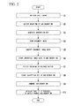
FIG. 2 is a flowchart illustrating the operation of the multifunction peripheral A in a first case; -
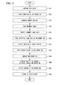
FIG. 3 is a flowchart illustrating the operation of the multifunction peripheral A in a second case; -
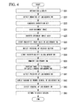
FIG. 4 is a flowchart illustrating the operation of the multifunction peripheral A in a third case; -
FIG. 5 is a flowchart illustrating the operation of the multifunction peripheral A in a fourth case; -
FIG. 6 is a flowchart illustrating the operation of the multifunction peripheral A in a fifth case; and -
FIG. 7 is a flowchart illustrating the operation of the multifunction peripheral A in a sixth case. - Hereinafter, an embodiment of the disclosure will be described with reference to the drawings.
Also, as an example of an electronic device according to the disclosure, a multifunction peripheral having combined functions of a copy machine, a printer, and a facsimile, which is a type of image forming device, will be described hereinafter. -
FIG. 1 is a function block diagram of a multifunction peripheral A according to an embodiment of the disclosure.
As shown inFIG. 1 , the multifunction peripheral A is an image forming device on which a USB memory RM can be mounted as a removable storage medium (removable medium), and includes a CPU (Central Processing Unit) 1, a ROM (Read Only Memory) 2, a RAM (Random Access Memory) 3, asensor group 4, asheet transport unit 5, animage reading unit 6, an imagedata storage unit 7, animage forming unit 8, acommunication interface unit 9, anoperation display unit 10, and aUSB port 11. - The
CPU 1 controls the overall operation of the multifunction peripheral A based on control programs stored in theROM 2, various detection signals received from thesensor group 4, document image data, print image data, and facsimile image data stored in the imagedata storage unit 7, various instructions input from a client computer (not illustrated) through thecommunication interface unit 9, and operating instructions input from theoperation display unit 10.
Hereinafter, the details of the control processing of theCPU 1 will be described as the operation of the multifunction peripheral A. - The
ROM 2 is a nonvolatile memory for storing the control programs executed by theCPU 1 and other data.
TheRAM 3 is a volatile memory which is used as a working area that is a temporary storage of data when theCPU 1 executes the control programs to perform various operations.
Thesensor group 4 includes various sensors that are necessary to perform the image forming operation, for example, such as an out of paper detection sensor, a sheet jam detection sensor, a sheet position detection sensor, a temperature sensor, and the like, and outputs various kinds of information detected by the respective sensors to theCPU 1 as detection signals. - The
sheet transport unit 5 includes a transport roller for transporting printing sheets that are housed in a sheet tray to theimage forming unit 8, a motor for driving the transport roller, a transport roller for transporting the printing sheets after the image forming process to an output tray (not illustrated), a motor for driving the transport roller, and the like. - The
image reading unit 6 is provided with an ADF (Automatic Document Feeder), a CCD (Charge Coupled Device) sensor, and the like, and reads images of documents that are sequentially fed by the ADF through the CCD sensor, and outputs document image data based on the document image.
Theimage reading unit 6 outputs the document image data to theCPU 1.
At the same time, theCPU 1 stores the document image data in the imagedata storage unit 7.
The imagedata storage unit 7 includes, for example, a flash memory, and stores the document image data, print image data that thecommunication interface unit 9 receives from a client computer, and facsimile image data that thecommunication interface unit 9 receives from a public network E, under the instruction of theCPU 1. - Under the control of the
CPU 1, theimage forming unit 8 transfers an image forming image which is formed by toner onto the print sheet that is transported from thesheet transport unit 5 based on document image data, print image data, or facsimile image data that is stored in the imagedata storage unit 7, and a fuser roller performs fusing of the image forming image.
Thecommunication interface unit 9 is connected to a client computer and a public network NW and transmits/receives various signals to/from the client computer and the public network NW. - The
operation display unit 10 is provided with a copy function switching key, a print function selection key, a scan function selection key, a facsimile function selection key, a start key, a stop/clear key, a power key, a numeric key (numeric input key), atouch panel 10a, and other various operation keys. Theoperation display unit 10 outputs operating instructions of the respective keys to theCPU 1 and displays various screens on thetouch panel 10a under the control of theCPU 1.
Additionally, the copy function selection key, the print function selection key, the scan function selection key, and the facsimile function selection key are keys for selecting operating modes of the respective functions in the multifunction peripheral A when a user selects the respective functions. - The
USB port 11 is a serial interface corresponding to the USB standard, and electrically connects to the USB memory RM when the USB memory RM is mounted.
In the case where theUSB port 11 is connected to the USB memory RM, it performs image data input/output with the USB memory RM under the control of theCPU 1. - Next, the operation of the multifunction peripheral A as configured above will be described.
- First, the operation of the multifunction peripheral A in a case where a release button of the USB memory RM is pressed as a removal operation of the USB memory RM by a user, which refers to a first case, will be described with reference to a flowchart of
FIG. 2 . - As shown in
FIG. 2 , if theCPU 1 detects that the login operation has been made by a user based on the operation signal input from theoperation display unit 10 while a login screen is displayed on the operation display unit 10 (touch panel 10a), theCPU 1 authenticates a login ID input by a user (step S1).
Furthermore, if the authentication of the login ID is completed and theCPU 1 detects that the USB memory RM is mounted on the USB port 11 (step S2), theCPU 1 generates an encryption key using a known encryption technology (step S3). - Here, it is preferable that the encryption key be generated, for example, using a ZIP file type encryption technology in consideration of the ease and compatibility of decoding in a general purpose computer.
Since a character string having a few characters can be used as an encryption key in the ZIP file, it is easy to input the character string to a general purpose computer.
In addition, since the ZIP file is supported as the standard in OS that is widely spread, such as Windows (registered trademark), it can be decrypted without introducing special software. - If the
CPU 1 detects that the scan operation has been performed by a user based on the operation signal input from theoperation display unit 10, theCPU 1 controls theimage reading unit 5 to read the image of the document set in theimage reading unit 5 by the user (step S4).
Then, theCPU 1 encrypts document image data obtained from theimage reading unit 5 using the encryption key generated in step S3 (step S5), and stores the document image data after the encryption (hereinafter referred to as "encrypted image data") in the USB memory RM through the USB port 11 (step S6). - Thereafter, if the
CPU 1 detects that the button to release the USB memory RM has been pressed (step S7), it stores the encryption key that is used to encrypt the document image data in the USB memory RM in association with the encrypted image data through the USB port 11 (step S8).
Although the button to release the USB memory RM is not shown inFIG. 1 , it may be displayed on thetouch panel 10a or a mechanical button may be separately installed as the release button. - Furthermore, the
CPU 1 unmounts the USB memory RM, that is, sets the USB memory RM in a safely removable state (step S9), and controls theoperation display unit 10 to display that the USB memory RM can be safely removed on the operation display unit 10 (step S10). - As described above, according to this embodiment, if leaving the USB memory RM on a device occurs (if removal operation of the USB memory RM is not made by the user), the encryption key is not stored in the USB memory RM, and thus a third person is unable to decrypt the encrypted image data stored in the USB memory RM to prevent the information leakage.
Also according to this embodiment, there is no need to register in advance the encryption key, and the user can decrypt the encrypted image data on a general purpose computer using the encryption key stored in the USB memory RM to secure the convenience of a user.
That is, according to this embodiment, it is possible to prevent the information leakage due to the leaving of the USB memory RM while securing the convenience of a user. - Additionally, the operation of the multifunction peripheral A in a case where a logout button is pressed as a removal operation of the USB memory RM by a user, which refers to a second case, will be described with reference to a flowchart of
FIG. 3 . - As shown in
FIG. 3 , if theCPU 1 detects that the login operation has been made by a user based on the operation signal input from theoperation display unit 10 while a login screen is displayed on the operation display unit 10 (touch panel 10a), theCPU 1 authenticates a login ID input by a user (step S11).
Furthermore, if the authentication of the login ID is completed and theCPU 1 detects that the USB memory RM is mounted on the USB port 11 (step S12), theCPU 1 generates an encryption key using a known encryption technology (step S 13). - If the
CPU 1 detects that the scan operation has been performed by a user based on the operation signal input from theoperation display unit 10, theCPU 1 controls theimage reading unit 5 to read the image of the document set in theimage reading unit 5 by the user (step S14).
Then, theCPU 1 encrypts document image data obtained from theimage reading unit 5 using the encryption key generated in step S 13 (step S 15), and stores the encrypted image data in the USB memory RM through the USB port 11 (step S16). - Thereafter, if the
CPU 1 detects that the logout button has been pressed (step S 17), it stores the encryption key, that is used to encrypt the document image data, in the USB memory RM in association with the encrypted image data through the USB port 11 (step S 18).
This logout button is displayed on thetouch panel 10a. - Then, the
CPU 1 unmounts the USB memory RM (step S 19), and controls theoperation display unit 10 to display that the USB memory RM can be safely removed on the operation display unit 10 (step S20).
Also, if theCPU 1 detects that the USB memory RM has been removed (step S21), it controls theoperation display unit 10 to display the login screen on the operation display unit 10 (step S22). - Even in the second case, in the same manner as the first case, the encryption key is stored in the USB memory RM only in the case where the removal of the USB memory is expressed through pressing of the logout button, and thus a third person is unable to decrypt the encrypted image data stored in the USB memory RM to prevent the information leakage.
- Next, the operation of the multifunction peripheral A in a case where a logout button is pressed in a state where the USB memory RM is not removed after a button to release the USB memory RM is pressed as a removal operation of the USB memory RM by a user, which refers to a third case, will be described with reference to a flowchart of
FIG. 4 . - As shown in
FIG. 4 , if theCPU 1 detects that the login operation has been made by a user based on the operation signal input from theoperation display unit 10 while a login screen is displayed on the operation display unit 10 (touch panel 10a), theCPU 1 authenticates a login ID input by a user (step S31).
Furthermore, if the authentication of the login ID is completed and theCPU 1 detects that the USB memory RM is mounted on the USB port 11 (step S32), theCPU 1 generates an encryption key using a known encryption technology (step S33). - If the
CPU 1 detects that the scan operation has been performed by a user based on the operation signal input from theoperation display unit 10, theCPU 1 controls theimage reading unit 5 to read the image of the document setimage reading unit 5 by the user (step S34).
Then, theCPU 1 encrypts document image data obtained from theimage reading unit 5 using the encryption key generated in step S33 (step S35), and stores the encrypted image data in the USB memory RM through the USB port 11 (step S36). - Thereafter, if the
CPU 1 detects that the button to release the USB memory RM has been pressed (step S37), it stores the encryption key, that is used to encrypt the document image data, in the USB memory RM in association with the encrypted image data through the USB port 11 (step S38).
Then, theCPU 1 unmounts the USB memory RM (step S39), and controls theoperation display unit 10 to display that the USB memory RM can be safely removed on the operation display unit 10 (step S40). - Thereafter, if the
CPU 1 detects that the logout button has been pressed (step S41), it controls theoperation display unit 10 to display a warning screen for instructing a user to remove the USB memory RM on the operation display unit 10 (step S42).
Then, if theCPU 1 detects that the USB memory RM has been removed (step S43), it controls theoperation display unit 10 to display the login screen (step S44). - As described above, in the case where the logout button is pressed in a state where the USB memory RM is not removed after the button to release the USB memory RM is pressed as the removal operation of the USB memory RM by the user, the leaving of the USB memory RM can be prevented by displaying the warning screen for instructing the user to remove the USB memory RM.
- Next, the operation of the multifunction peripheral A in a fourth case (where a removal operation of the USB memory RM by a user is not performed even though a predetermined time elapses after the encrypted image data is stored in the USB memory RM) will be described with reference to a flowchart of
FIG. 5 . - As shown in
FIG. 5 , if theCPU 1 detects that the login operation has been made by a user based on the operation signal input from theoperation display unit 10 while a login screen is displayed on the operation display unit 10 (touch panel 10a), theCPU 1 authenticates a login ID input by a user (step S51).
In addition, if the authentication of the login ID is completed and theCPU 1 detects that the USB memory RM is mounted on the USB port 11 (step S52), theCPU 1 generates an encryption key using a known encryption technology (step S53). - If the
CPU 1 detects that the scan operation has been performed by a user based on the operation signal input from theoperation display unit 10, theCPU 1 controls theimage reading unit 5 to read the image of the document setimage reading unit 5 by the user (step S54).
Then, theCPU 1 encrypts document image data obtained from theimage reading unit 5 using the encryption key generated in step S53 (step S55), and stores the encrypted image data in the USB memory RM through the USB port 11 (step S56). - If a timeout of an automatic logout function occurs after the encrypted image data is stored in the USB memory RM (step S57), the
CPU 1 unmounts the USB memory RM (step S58), and performs automatic logout (step S59).
The automatic logout function is an existing function to automatically log out in the case where no operation is made by the user for a predetermined time. - As described above, if the timeout of the automatic logout function occurs (if any operation to the multifunction peripheral A is not made by the user for the predetermined time) after the encrypted image data is stored in the USB memory RM, encryption key is not stored in the USB memory RM, and thus it becomes possible to remove the USB memory RM.
Through this, even if the user has been away from the multifunction peripheral A in a state where the USB memory RM is left on the multifunction peripheral A, the encryption key is not stored in the USB memory RM, and thus it is possible to prevent the information leakage to a third person. - Next, in the fifth case, the operation of the multifunction peripheral A will be described with reference to a flowchart of
FIG. 6 , in a case where a button to release the USB memory RM is pressed as a removal operation of the USB memory RM by a user, an encryption key is stored in the USB memory RM, and the USB memory RM is not removed even though a predetermined time elapses after the USB memory RM enters a removable state. - As shown in
FIG. 6 , if theCPU 1 detects that the login operation has been made by a user based on the operation signal input from theoperation display unit 10 while a login screen is displayed on the operation display unit 10 (touch panel 10a), theCPU 1 authenticates a login ID input by a user (step S61).
Additionally, if the authentication of the login ID is completed and theCPU 1 detects that the USB memory RM is mounted on the USB port 11 (step S62), theCPU 1 generates an encryption key using a known encryption technology (step S63). - If the
CPU 1 detects that the scan operation has been performed by a user based on the operation signal input from theoperation display unit 10, theCPU 1 controls theimage reading unit 5 to read the image of the document setimage reading unit 5 by the user (step S64).
Then, theCPU 1 encrypts document image data obtained from theimage reading unit 5 using the encryption key generated in step S63 (step S65), and stores the encrypted image data in the USB memory RM through the USB port 11 (step S66). - Thereafter, if the
CPU 1 detects that the button to release the USB memory RM has been pressed (step S67), it stores the encryption key that is used to encrypt the document image data in the USB memory RM in association with the encrypted image data through the USB port 11 (step S68).
Also, theCPU 1 unmounts the USB memory RM (step S69), and controls theoperation display unit 10 to display that the USB memory RM can be safely removed on the operation display unit 10 (step S70). - If a timeout of an automatic logout function occurs after the USB memory RM is unmounted (step S71), the
CPU 1 re-mounts the USB memory RM (restore the connection state between theUSB port 11 and the USB memory RM) (step S72).
Then, theCPU 1 unmounts the USB memory RM again (step S74) after deleting the encryption key from the USB memory RM (step S73), and controls theoperation display unit 10 to display the login screen thereon (step S75). - As described above, if the button to release the USB memory RM is pressed as the removal operation of the USB memory RM by the user, the encryption key is stored in the USB memory RM, and the timeout of the automatic logout function occurs after the USB memory RM enters a removable state (if no operation to the multifunction peripheral A is made by the user for the predetermined time), the encryption key is deleted from the USB memory RM.
Through this, even if the user has been away from the multifunction peripheral A in a state where the USB memory RM is left on the multifunction peripheral A, the encryption key is not stored in the USB memory RM through deletion of the encryption key, and thus it is possible to prevent information leakage to a third person. - Further, the operation of the multifunction peripheral A will be described with reference to a flowchart of
FIG. 7 , in a sixth case (where a logout button is pressed as a removal operation of the USB memory RM by a user, an encryption key is stored in the USB memory RM, and the USB memory RM is not removed even though a predetermined time elapses after the USB memory RM enters a removable state). - As shown in
FIG. 7 , if theCPU 1 detects that the login operation has been made by a user based on the operation signal input from theoperation display unit 10 while a login screen is displayed on the operation display unit 10 (touch panel 10a), theCPU 1 authenticates a login ID input by a user (step S81).
Further, if the authentication of the login ID is completed and theCPU 1 detects that the USB memory RM is mounted on the USB port 11 (step S82), theCPU 1 generates an encryption key using a known encryption technology (step S83). - If the
CPU 1 detects that the scan operation has been performed by a user based on the operation signal input from theoperation display unit 10, theCPU 1 controls theimage reading unit 5 to read the image of the document setimage reading unit 5 by the user (step S84).
Then, theCPU 1 encrypts document image data obtained from theimage reading unit 5 using the encryption key generated in step S83 (step S85), and stores the encrypted image data in the USB memory RM through the USB port 11 (step S86). - Thereafter, if the
CPU 1 detects that the logout button has been pressed (step S87), it stores the encryption key that is used to encrypt the document image data in the USB memory RM in association with the encrypted image data through the USB port 11 (step S88).
Further, theCPU 1 unmounts the USB memory RM (step S89), and controls theoperation display unit 10 to display that the USB memory RM can be safely removed on the operation display unit 10 (step S90). - If the
CPU 1 starts a timer after unmounting the USB memory RM and a timeout of an automatic logout function occurs in a state where the USB memory RM is not removed (step S91), theCPU 1 re-mounts the USB memory RM (step S92).
Then, theCPU 1 unmounts the USB memory RM again (step S94) after deleting the encryption key from the USB memory RM (step S93), and controls theoperation display unit 10 to display the login screen thereon (step S95). - As described above, if the logout button is pressed as the removal operation of the USB memory RM by the user, the encryption key is stored in the USB memory RM, and the USB memory RM is not removed even though the predetermined time elapses after the USB memory RM enters a removable state, the encryption key is deleted from the USB memory RM.
Through this, even if the user has been away from the multifunction peripheral A in a state where the USB memory RM is left on the multifunction peripheral A, the encryption key is not stored in the USB memory RM through deletion of the encryption key, and thus it is possible to prevent the information leakage to a third person. - As described above, although one embodiment of the present disclosure has been described, the present disclosure is not limited to the embodiment, and various modifications can be made without departing from the scope of the disclosure.
For example, in the above-described embodiment, the USB memory RM is exemplified as the removable storage medium (removable medium). However, the present disclosure is not limited thereto, and can be applied to multifunction peripherals that can mount overall storage media, such as an SD card, a compact flash (registered trademark), a memory stick, a smart medium, a floppy (registered trademark) disk, a CD-RW, a DVD-RW, a MO disk, and the like. - Also, in the above-described embodiment, the pressing the button to release the USB memory RM or the pressing of the logout button has been exemplified as the removal operation of the USB memory RM by the user. However, other removal operations of the USB memory RM may be used.
In addition, in the above-described embodiment, it is exemplified that the encryption key is generated at a time when the mounting of the USB memory RM onto the multifunction peripheral A is detected. However, the timing for generating the encryption key is not limited thereto, and for example, the encryption key may be generated at a time when the login authentication is completed.
Furthermore, according to the above-described embodiment, description has been made with reference to the multifunction peripheral A as the image forming device. However, the present disclosure is not limited thereto, and the present disclosure can be applied to other image forming devices such as a copy machine, a printer, a scanner, and a facsimile.
Additionally, the disclosure can be applied to any electronic device that is provided with a storage medium interface connected to a removable storage medium as other electronic devices except for the image forming device.
While preferred embodiments of the disclosure have been described and illustrated above, it should be understood that these are exemplary of the disclosure and are not to be considered as limiting. Additions, omissions, substitutions, and other modifications can be made without departing from the scope of the present disclosure. Accordingly, the disclosure is not to be considered as being limited by the foregoing description, and is only limited by the scope of the appended claims. -
- A: a multifunction peripheral
- 1: a CPU (Central Processing Unit)
- 2: a ROM (Read Only Memory)
- 3: RAM (Random Access Memory)
- 4: a sensor group
- 5: a sheet transport unit
- 6: an image reading unit
- 7: an image data storage unit
- 8: an image forming unit
- 9: a communication interface unit
- 10: an operation display unit
- 10a: a touch panel
- 11: a USB port
- RM: USB memory
Claims (5)
- An electronic device (A) causing a removable storage medium (RM) to store data, the electronic device comprising:the removable storage medium (RM);a storage medium interface (11) connecting to the storage medium (RM); anda control unit (1) generating an encryption key at a predetermined timing, encrypting data to be stored in the storage medium (RM) using the encryption key, storing the encrypted data in the storage medium (RM), and storing the encryption key in the storage medium (RM) in association with the encrypted data if it is detected that a removal operation of the storage medium (RM) is made by a user.
- The electronic device (A) according to claim 1, wherein
the control unit (1) stores the encryption key in the storage medium when detecting that a button to release the storage medium (RM) is pressed as the removal operation of the storage medium (RM) by the user, sets the storage medium (RM) in a removable state, and if a timeout of an automatic logout function occurs in a state where no operation is made by the user for a predetermined time, restores a connection state between the storage medium interface (11) and the storage medium (RM) to delete the encryption key from the storage medium (RM). - The electronic device (A) according to claim 1 or 2, wherein
the control unit (1) stores the encryption key in the storage medium (RM) when detecting that a logout button is pressed as the removal operation of the storage medium (RM) by the user, starts a timer after setting the storage medium (RM) in a removable state, and if a timeout of the timer occurs in a state where the storage medium (RM) is left on the device, restores a connection state between the storage medium interface (11) and the storage medium (RM) to delete the encryption key from the storage medium (RM). - The electronic device (A) according to anyone of the preceding claims, wherein
the control unit (1) encrypts the data to be stored in the storage medium (RM) using the encryption key, stores the encrypted data in the storage medium (RM), and if a timeout of an automatic logout function occurs in a state where no operation is made by the user for a predetermined time, deletes the encryption key stored in the storage medium (RM), and sets the storage medium in a removable state. - The electronic device (A) according to anyone of the preceding claims, wherein
the control unit (1) stores the encryption key in the storage medium (RM) if it is detected that a button to release the storage medium (RM) is pressed as the removal operation of the storage medium by the user, sets the storage medium in a removable state, and if it is detected that a logout button is pressed thereafter, warns the user to remove the storage medium.
Applications Claiming Priority (1)
| Application Number | Priority Date | Filing Date | Title |
|---|---|---|---|
| JP2011145100A JP5393733B2 (en) | 2011-06-30 | 2011-06-30 | Electronics |
Publications (2)
| Publication Number | Publication Date |
|---|---|
| EP2541460A1 true EP2541460A1 (en) | 2013-01-02 |
| EP2541460B1 EP2541460B1 (en) | 2017-05-17 |
Family
ID=46633997
Family Applications (1)
| Application Number | Title | Priority Date | Filing Date |
|---|---|---|---|
| EP12174011.2A Not-in-force EP2541460B1 (en) | 2011-06-30 | 2012-06-28 | Electronic device for prevention of data leakage via a removable storage medium |
Country Status (5)
| Country | Link |
|---|---|
| US (1) | US8935540B2 (en) |
| EP (1) | EP2541460B1 (en) |
| JP (1) | JP5393733B2 (en) |
| KR (1) | KR101377794B1 (en) |
| CN (1) | CN102866959B (en) |
Families Citing this family (7)
| Publication number | Priority date | Publication date | Assignee | Title |
|---|---|---|---|---|
| US10181055B2 (en) * | 2007-09-27 | 2019-01-15 | Clevx, Llc | Data security system with encryption |
| CA2754560C (en) * | 2009-03-03 | 2019-04-09 | Ats Automation Tooling Systems Inc. | Multi-mode and multi-pitch conveyor system |
| CN105378681B (en) * | 2013-07-08 | 2019-09-13 | 英派尔科技开发有限公司 | External memory access control |
| JP6157346B2 (en) * | 2013-12-27 | 2017-07-05 | 京セラドキュメントソリューションズ株式会社 | Image processing system and log recording method |
| US10296206B2 (en) * | 2014-09-23 | 2019-05-21 | Microsoft Technology Licensing, Llc | Multi-finger touchpad gestures |
| JP6990994B2 (en) * | 2017-05-26 | 2022-01-12 | キヤノン株式会社 | Information processing equipment, its control method, and programs |
| JP7767107B2 (en) * | 2021-10-25 | 2025-11-11 | シャープ株式会社 | Information processing apparatus, image forming apparatus, and control method |
Citations (4)
| Publication number | Priority date | Publication date | Assignee | Title |
|---|---|---|---|---|
| US20070250717A1 (en) * | 2006-04-20 | 2007-10-25 | Kazuyuki Kumagai | Image forming apparatus, image reproducing apparatus and image processing system |
| US20080178009A1 (en) * | 2006-09-28 | 2008-07-24 | Sony Corporation | Electronic apparatus and information processing method |
| US20090052664A1 (en) * | 2007-08-20 | 2009-02-26 | Brian Gerard Goodman | Bulk Data Erase Utilizing An Encryption Technique |
| US20090119785A1 (en) * | 2007-11-05 | 2009-05-07 | David Carroll Challener | System and Method for Secure Usage of Peripheral Devices Using Shared Secrets |
Family Cites Families (25)
| Publication number | Priority date | Publication date | Assignee | Title |
|---|---|---|---|---|
| JPH10240883A (en) * | 1997-02-24 | 1998-09-11 | Toshiba Corp | IC card system and security method for IC card system |
| US20050182822A1 (en) * | 2004-02-17 | 2005-08-18 | Daniel Stuart W. | Imaging device with memory device interface |
| JP4198628B2 (en) * | 2004-04-08 | 2008-12-17 | 株式会社リコー | Information recording apparatus, recording operation control method thereof, and recording operation control program |
| JP4420450B2 (en) * | 2004-06-24 | 2010-02-24 | 株式会社リコー | Image recording device |
| WO2006098009A1 (en) * | 2005-03-16 | 2006-09-21 | Fujitsu Limited | Apparatus and method for managing key in library apparatus |
| JP2006350494A (en) * | 2005-06-14 | 2006-12-28 | Hitachi High-Technologies Corp | Information processing device |
| JP4921862B2 (en) | 2006-06-12 | 2012-04-25 | 株式会社東芝 | Information recording / reproducing apparatus and method |
| JP3899365B1 (en) * | 2006-07-05 | 2007-03-28 | 有限会社トゥールビヨン | Information storage device |
| JP2008028575A (en) * | 2006-07-19 | 2008-02-07 | Hitachi Kokusai Electric Inc | Receiver |
| JP4827684B2 (en) * | 2006-10-17 | 2011-11-30 | 有限会社トゥールビヨン | Information storage device |
| JP4009315B1 (en) * | 2007-02-14 | 2007-11-14 | 有限会社トゥールビヨン | Security adapter |
| US8281407B2 (en) * | 2008-12-09 | 2012-10-02 | Pitney Bowes Inc. | In-line decryption device for securely printing documents |
| JP5156604B2 (en) | 2008-12-10 | 2013-03-06 | 京セラドキュメントソリューションズ株式会社 | Electronic device and storage medium management system |
| JP2010141501A (en) | 2008-12-10 | 2010-06-24 | Kyocera Mita Corp | Electronic apparatus |
| JP2010146500A (en) | 2008-12-22 | 2010-07-01 | Kyocera Mita Corp | Electronic apparatus |
| JP2010225000A (en) * | 2009-03-25 | 2010-10-07 | Nec Corp | Password setting system for detachable recording medium |
| JP2010258679A (en) | 2009-04-23 | 2010-11-11 | Kyocera Mita Corp | Electronic apparatus |
| JP5172776B2 (en) * | 2009-05-12 | 2013-03-27 | 京セラドキュメントソリューションズ株式会社 | Electronics |
| JP4787893B2 (en) * | 2009-07-07 | 2011-10-05 | 富士通株式会社 | Key data storage device, method, library device, and storage device |
| JP5202487B2 (en) * | 2009-09-24 | 2013-06-05 | 京セラドキュメントソリューションズ株式会社 | Image reading device |
| JP2011109444A (en) * | 2009-11-18 | 2011-06-02 | Panasonic Corp | Content protecting method, content reproducing device, program, and program recording medium |
| JP5505010B2 (en) * | 2010-03-19 | 2014-05-28 | 富士通株式会社 | Storage medium adapter and data access disabling method |
| JP2011233087A (en) * | 2010-04-30 | 2011-11-17 | Fujitsu Kansai-Chubu Net-Tech Ltd | Storage, control method and computer program |
| US8549585B2 (en) * | 2010-06-14 | 2013-10-01 | International Business Machines Corporation | Method and apparatus to implement secured, layered logout from a computer system |
| JP5652297B2 (en) * | 2011-03-30 | 2015-01-14 | 富士通株式会社 | Information terminal, information leakage prevention method and information leakage prevention program |
-
2011
- 2011-06-30 JP JP2011145100A patent/JP5393733B2/en not_active Expired - Fee Related
-
2012
- 2012-06-07 CN CN201210193015.5A patent/CN102866959B/en not_active Expired - Fee Related
- 2012-06-18 KR KR1020120064979A patent/KR101377794B1/en not_active Expired - Fee Related
- 2012-06-27 US US13/534,884 patent/US8935540B2/en not_active Expired - Fee Related
- 2012-06-28 EP EP12174011.2A patent/EP2541460B1/en not_active Not-in-force
Patent Citations (4)
| Publication number | Priority date | Publication date | Assignee | Title |
|---|---|---|---|---|
| US20070250717A1 (en) * | 2006-04-20 | 2007-10-25 | Kazuyuki Kumagai | Image forming apparatus, image reproducing apparatus and image processing system |
| US20080178009A1 (en) * | 2006-09-28 | 2008-07-24 | Sony Corporation | Electronic apparatus and information processing method |
| US20090052664A1 (en) * | 2007-08-20 | 2009-02-26 | Brian Gerard Goodman | Bulk Data Erase Utilizing An Encryption Technique |
| US20090119785A1 (en) * | 2007-11-05 | 2009-05-07 | David Carroll Challener | System and Method for Secure Usage of Peripheral Devices Using Shared Secrets |
Also Published As
| Publication number | Publication date |
|---|---|
| US20130007472A1 (en) | 2013-01-03 |
| EP2541460B1 (en) | 2017-05-17 |
| KR20130007433A (en) | 2013-01-18 |
| JP5393733B2 (en) | 2014-01-22 |
| CN102866959B (en) | 2015-07-08 |
| CN102866959A (en) | 2013-01-09 |
| JP2013012964A (en) | 2013-01-17 |
| US8935540B2 (en) | 2015-01-13 |
| KR101377794B1 (en) | 2014-03-25 |
Similar Documents
| Publication | Publication Date | Title |
|---|---|---|
| US9513701B2 (en) | Information processing apparatus, information processing method, and computer-readable medium | |
| EP2541460B1 (en) | Electronic device for prevention of data leakage via a removable storage medium | |
| JP5172776B2 (en) | Electronics | |
| JP4470957B2 (en) | Image processing system and image reading apparatus | |
| CN107436739B (en) | Image processing apparatus and control method | |
| US10574854B2 (en) | Imaging processing apparatus for receiving print data from server and performing image processing and method for controlling the same | |
| US10776494B2 (en) | Method for verifying forgery and falsification of executable file in image forming apparatus and image forming apparatus using same | |
| US20080168554A1 (en) | Image forming apparatus and method of outputting | |
| US8605314B2 (en) | Apparatus, method and computer-readable storage medium for outputting images to electronic paper | |
| JP5911795B2 (en) | Image forming apparatus and image forming method | |
| JP2010258679A (en) | Electronic apparatus | |
| JP5000346B2 (en) | Image processing apparatus, image processing method, program, and recording medium | |
| JP2010141501A (en) | Electronic apparatus | |
| US20080199008A1 (en) | Image forming device and image forming method | |
| JP2006303563A (en) | Image processing device | |
| KR101269468B1 (en) | Image forming apparatus and method of outputting document thereof | |
| US10564907B2 (en) | Image forming apparatus, display control method, and storage medium | |
| JP5305160B2 (en) | Image forming apparatus, processing method thereof, and program | |
| JP2010146500A (en) | Electronic apparatus | |
| JP5092641B2 (en) | Image processing apparatus, image data storage method, and computer program | |
| US11816233B2 (en) | Information processing apparatus | |
| US12277037B2 (en) | Information processing apparatus | |
| JP4572884B2 (en) | Image forming apparatus | |
| CN119653017A (en) | Image forming device, image forming device control method, and storage medium | |
| JPWO2022030278A5 (en) |
Legal Events
| Date | Code | Title | Description |
|---|---|---|---|
| PUAI | Public reference made under article 153(3) epc to a published international application that has entered the european phase |
Free format text: ORIGINAL CODE: 0009012 |
|
| AK | Designated contracting states |
Kind code of ref document: A1 Designated state(s): AL AT BE BG CH CY CZ DE DK EE ES FI FR GB GR HR HU IE IS IT LI LT LU LV MC MK MT NL NO PL PT RO RS SE SI SK SM TR |
|
| AX | Request for extension of the european patent |
Extension state: BA ME |
|
| 17P | Request for examination filed |
Effective date: 20130701 |
|
| RBV | Designated contracting states (corrected) |
Designated state(s): AL AT BE BG CH CY CZ DE DK EE ES FI FR GB GR HR HU IE IS IT LI LT LU LV MC MK MT NL NO PL PT RO RS SE SI SK SM TR |
|
| REG | Reference to a national code |
Ref country code: DE Ref legal event code: R079 Ref document number: 602012032480 Country of ref document: DE Free format text: PREVIOUS MAIN CLASS: G06F0021240000 Ipc: G06F0021790000 |
|
| GRAP | Despatch of communication of intention to grant a patent |
Free format text: ORIGINAL CODE: EPIDOSNIGR1 |
|
| RIC1 | Information provided on ipc code assigned before grant |
Ipc: G06F 12/14 20060101ALI20161124BHEP Ipc: G06F 15/167 20060101ALI20161124BHEP Ipc: G06F 21/79 20130101AFI20161124BHEP |
|
| INTG | Intention to grant announced |
Effective date: 20161212 |
|
| GRAS | Grant fee paid |
Free format text: ORIGINAL CODE: EPIDOSNIGR3 |
|
| GRAA | (expected) grant |
Free format text: ORIGINAL CODE: 0009210 |
|
| AK | Designated contracting states |
Kind code of ref document: B1 Designated state(s): AL AT BE BG CH CY CZ DE DK EE ES FI FR GB GR HR HU IE IS IT LI LT LU LV MC MK MT NL NO PL PT RO RS SE SI SK SM TR |
|
| REG | Reference to a national code |
Ref country code: GB Ref legal event code: FG4D |
|
| REG | Reference to a national code |
Ref country code: CH Ref legal event code: EP |
|
| REG | Reference to a national code |
Ref country code: IE Ref legal event code: FG4D |
|
| REG | Reference to a national code |
Ref country code: AT Ref legal event code: REF Ref document number: 895084 Country of ref document: AT Kind code of ref document: T Effective date: 20170615 |
|
| REG | Reference to a national code |
Ref country code: FR Ref legal event code: PLFP Year of fee payment: 6 |
|
| REG | Reference to a national code |
Ref country code: DE Ref legal event code: R096 Ref document number: 602012032480 Country of ref document: DE |
|
| REG | Reference to a national code |
Ref country code: NL Ref legal event code: MP Effective date: 20170517 |
|
| REG | Reference to a national code |
Ref country code: LT Ref legal event code: MG4D |
|
| REG | Reference to a national code |
Ref country code: AT Ref legal event code: MK05 Ref document number: 895084 Country of ref document: AT Kind code of ref document: T Effective date: 20170517 |
|
| PG25 | Lapsed in a contracting state [announced via postgrant information from national office to epo] |
Ref country code: ES Free format text: LAPSE BECAUSE OF FAILURE TO SUBMIT A TRANSLATION OF THE DESCRIPTION OR TO PAY THE FEE WITHIN THE PRESCRIBED TIME-LIMIT Effective date: 20170517 Ref country code: LT Free format text: LAPSE BECAUSE OF FAILURE TO SUBMIT A TRANSLATION OF THE DESCRIPTION OR TO PAY THE FEE WITHIN THE PRESCRIBED TIME-LIMIT Effective date: 20170517 Ref country code: GR Free format text: LAPSE BECAUSE OF FAILURE TO SUBMIT A TRANSLATION OF THE DESCRIPTION OR TO PAY THE FEE WITHIN THE PRESCRIBED TIME-LIMIT Effective date: 20170818 Ref country code: NO Free format text: LAPSE BECAUSE OF FAILURE TO SUBMIT A TRANSLATION OF THE DESCRIPTION OR TO PAY THE FEE WITHIN THE PRESCRIBED TIME-LIMIT Effective date: 20170817 Ref country code: HR Free format text: LAPSE BECAUSE OF FAILURE TO SUBMIT A TRANSLATION OF THE DESCRIPTION OR TO PAY THE FEE WITHIN THE PRESCRIBED TIME-LIMIT Effective date: 20170517 Ref country code: AT Free format text: LAPSE BECAUSE OF FAILURE TO SUBMIT A TRANSLATION OF THE DESCRIPTION OR TO PAY THE FEE WITHIN THE PRESCRIBED TIME-LIMIT Effective date: 20170517 Ref country code: FI Free format text: LAPSE BECAUSE OF FAILURE TO SUBMIT A TRANSLATION OF THE DESCRIPTION OR TO PAY THE FEE WITHIN THE PRESCRIBED TIME-LIMIT Effective date: 20170517 |
|
| PG25 | Lapsed in a contracting state [announced via postgrant information from national office to epo] |
Ref country code: SE Free format text: LAPSE BECAUSE OF FAILURE TO SUBMIT A TRANSLATION OF THE DESCRIPTION OR TO PAY THE FEE WITHIN THE PRESCRIBED TIME-LIMIT Effective date: 20170517 Ref country code: IS Free format text: LAPSE BECAUSE OF FAILURE TO SUBMIT A TRANSLATION OF THE DESCRIPTION OR TO PAY THE FEE WITHIN THE PRESCRIBED TIME-LIMIT Effective date: 20170917 Ref country code: LV Free format text: LAPSE BECAUSE OF FAILURE TO SUBMIT A TRANSLATION OF THE DESCRIPTION OR TO PAY THE FEE WITHIN THE PRESCRIBED TIME-LIMIT Effective date: 20170517 Ref country code: NL Free format text: LAPSE BECAUSE OF FAILURE TO SUBMIT A TRANSLATION OF THE DESCRIPTION OR TO PAY THE FEE WITHIN THE PRESCRIBED TIME-LIMIT Effective date: 20170517 Ref country code: PL Free format text: LAPSE BECAUSE OF FAILURE TO SUBMIT A TRANSLATION OF THE DESCRIPTION OR TO PAY THE FEE WITHIN THE PRESCRIBED TIME-LIMIT Effective date: 20170517 Ref country code: BG Free format text: LAPSE BECAUSE OF FAILURE TO SUBMIT A TRANSLATION OF THE DESCRIPTION OR TO PAY THE FEE WITHIN THE PRESCRIBED TIME-LIMIT Effective date: 20170817 Ref country code: RS Free format text: LAPSE BECAUSE OF FAILURE TO SUBMIT A TRANSLATION OF THE DESCRIPTION OR TO PAY THE FEE WITHIN THE PRESCRIBED TIME-LIMIT Effective date: 20170517 |
|
| PG25 | Lapsed in a contracting state [announced via postgrant information from national office to epo] |
Ref country code: DK Free format text: LAPSE BECAUSE OF FAILURE TO SUBMIT A TRANSLATION OF THE DESCRIPTION OR TO PAY THE FEE WITHIN THE PRESCRIBED TIME-LIMIT Effective date: 20170517 Ref country code: SK Free format text: LAPSE BECAUSE OF FAILURE TO SUBMIT A TRANSLATION OF THE DESCRIPTION OR TO PAY THE FEE WITHIN THE PRESCRIBED TIME-LIMIT Effective date: 20170517 Ref country code: EE Free format text: LAPSE BECAUSE OF FAILURE TO SUBMIT A TRANSLATION OF THE DESCRIPTION OR TO PAY THE FEE WITHIN THE PRESCRIBED TIME-LIMIT Effective date: 20170517 Ref country code: CZ Free format text: LAPSE BECAUSE OF FAILURE TO SUBMIT A TRANSLATION OF THE DESCRIPTION OR TO PAY THE FEE WITHIN THE PRESCRIBED TIME-LIMIT Effective date: 20170517 Ref country code: RO Free format text: LAPSE BECAUSE OF FAILURE TO SUBMIT A TRANSLATION OF THE DESCRIPTION OR TO PAY THE FEE WITHIN THE PRESCRIBED TIME-LIMIT Effective date: 20170517 |
|
| REG | Reference to a national code |
Ref country code: CH Ref legal event code: PL |
|
| REG | Reference to a national code |
Ref country code: DE Ref legal event code: R097 Ref document number: 602012032480 Country of ref document: DE |
|
| PG25 | Lapsed in a contracting state [announced via postgrant information from national office to epo] |
Ref country code: SM Free format text: LAPSE BECAUSE OF FAILURE TO SUBMIT A TRANSLATION OF THE DESCRIPTION OR TO PAY THE FEE WITHIN THE PRESCRIBED TIME-LIMIT Effective date: 20170517 Ref country code: IT Free format text: LAPSE BECAUSE OF FAILURE TO SUBMIT A TRANSLATION OF THE DESCRIPTION OR TO PAY THE FEE WITHIN THE PRESCRIBED TIME-LIMIT Effective date: 20170517 |
|
| PLBE | No opposition filed within time limit |
Free format text: ORIGINAL CODE: 0009261 |
|
| STAA | Information on the status of an ep patent application or granted ep patent |
Free format text: STATUS: NO OPPOSITION FILED WITHIN TIME LIMIT |
|
| REG | Reference to a national code |
Ref country code: IE Ref legal event code: MM4A |
|
| 26N | No opposition filed |
Effective date: 20180220 |
|
| PG25 | Lapsed in a contracting state [announced via postgrant information from national office to epo] |
Ref country code: LI Free format text: LAPSE BECAUSE OF NON-PAYMENT OF DUE FEES Effective date: 20170630 Ref country code: CH Free format text: LAPSE BECAUSE OF NON-PAYMENT OF DUE FEES Effective date: 20170630 Ref country code: LU Free format text: LAPSE BECAUSE OF NON-PAYMENT OF DUE FEES Effective date: 20170628 Ref country code: IE Free format text: LAPSE BECAUSE OF NON-PAYMENT OF DUE FEES Effective date: 20170628 |
|
| REG | Reference to a national code |
Ref country code: FR Ref legal event code: PLFP Year of fee payment: 7 |
|
| PG25 | Lapsed in a contracting state [announced via postgrant information from national office to epo] |
Ref country code: SI Free format text: LAPSE BECAUSE OF FAILURE TO SUBMIT A TRANSLATION OF THE DESCRIPTION OR TO PAY THE FEE WITHIN THE PRESCRIBED TIME-LIMIT Effective date: 20170517 |
|
| REG | Reference to a national code |
Ref country code: BE Ref legal event code: MM Effective date: 20170630 |
|
| PG25 | Lapsed in a contracting state [announced via postgrant information from national office to epo] |
Ref country code: BE Free format text: LAPSE BECAUSE OF NON-PAYMENT OF DUE FEES Effective date: 20170630 |
|
| PG25 | Lapsed in a contracting state [announced via postgrant information from national office to epo] |
Ref country code: MT Free format text: LAPSE BECAUSE OF NON-PAYMENT OF DUE FEES Effective date: 20170628 |
|
| PG25 | Lapsed in a contracting state [announced via postgrant information from national office to epo] |
Ref country code: HU Free format text: LAPSE BECAUSE OF FAILURE TO SUBMIT A TRANSLATION OF THE DESCRIPTION OR TO PAY THE FEE WITHIN THE PRESCRIBED TIME-LIMIT; INVALID AB INITIO Effective date: 20120628 Ref country code: MC Free format text: LAPSE BECAUSE OF FAILURE TO SUBMIT A TRANSLATION OF THE DESCRIPTION OR TO PAY THE FEE WITHIN THE PRESCRIBED TIME-LIMIT Effective date: 20170517 |
|
| PG25 | Lapsed in a contracting state [announced via postgrant information from national office to epo] |
Ref country code: CY Free format text: LAPSE BECAUSE OF NON-PAYMENT OF DUE FEES Effective date: 20170517 |
|
| PG25 | Lapsed in a contracting state [announced via postgrant information from national office to epo] |
Ref country code: MK Free format text: LAPSE BECAUSE OF FAILURE TO SUBMIT A TRANSLATION OF THE DESCRIPTION OR TO PAY THE FEE WITHIN THE PRESCRIBED TIME-LIMIT Effective date: 20170517 |
|
| PG25 | Lapsed in a contracting state [announced via postgrant information from national office to epo] |
Ref country code: TR Free format text: LAPSE BECAUSE OF FAILURE TO SUBMIT A TRANSLATION OF THE DESCRIPTION OR TO PAY THE FEE WITHIN THE PRESCRIBED TIME-LIMIT Effective date: 20170517 |
|
| PG25 | Lapsed in a contracting state [announced via postgrant information from national office to epo] |
Ref country code: PT Free format text: LAPSE BECAUSE OF FAILURE TO SUBMIT A TRANSLATION OF THE DESCRIPTION OR TO PAY THE FEE WITHIN THE PRESCRIBED TIME-LIMIT Effective date: 20170517 |
|
| PG25 | Lapsed in a contracting state [announced via postgrant information from national office to epo] |
Ref country code: AL Free format text: LAPSE BECAUSE OF FAILURE TO SUBMIT A TRANSLATION OF THE DESCRIPTION OR TO PAY THE FEE WITHIN THE PRESCRIBED TIME-LIMIT Effective date: 20170517 |
|
| PGFP | Annual fee paid to national office [announced via postgrant information from national office to epo] |
Ref country code: DE Payment date: 20200617 Year of fee payment: 9 Ref country code: FR Payment date: 20200512 Year of fee payment: 9 |
|
| PGFP | Annual fee paid to national office [announced via postgrant information from national office to epo] |
Ref country code: GB Payment date: 20200618 Year of fee payment: 9 |
|
| REG | Reference to a national code |
Ref country code: DE Ref legal event code: R119 Ref document number: 602012032480 Country of ref document: DE |
|
| GBPC | Gb: european patent ceased through non-payment of renewal fee |
Effective date: 20210628 |
|
| PG25 | Lapsed in a contracting state [announced via postgrant information from national office to epo] |
Ref country code: GB Free format text: LAPSE BECAUSE OF NON-PAYMENT OF DUE FEES Effective date: 20210628 Ref country code: DE Free format text: LAPSE BECAUSE OF NON-PAYMENT OF DUE FEES Effective date: 20220101 |
|
| PG25 | Lapsed in a contracting state [announced via postgrant information from national office to epo] |
Ref country code: FR Free format text: LAPSE BECAUSE OF NON-PAYMENT OF DUE FEES Effective date: 20210630 |