EP2541369B1 - Assembly of a hand held computer terminal housing - Google Patents
Assembly of a hand held computer terminal housing Download PDFInfo
- Publication number
- EP2541369B1 EP2541369B1 EP12172839.8A EP12172839A EP2541369B1 EP 2541369 B1 EP2541369 B1 EP 2541369B1 EP 12172839 A EP12172839 A EP 12172839A EP 2541369 B1 EP2541369 B1 EP 2541369B1
- Authority
- EP
- European Patent Office
- Prior art keywords
- hand held
- computer terminal
- main body
- held computer
- cap
- Prior art date
- Legal status (The legal status is an assumption and is not a legal conclusion. Google has not performed a legal analysis and makes no representation as to the accuracy of the status listed.)
- Active
Links
Images

Classifications
-
- G—PHYSICS
- G06—COMPUTING OR CALCULATING; COUNTING
- G06F—ELECTRIC DIGITAL DATA PROCESSING
- G06F1/00—Details not covered by groups G06F3/00 - G06F13/00 and G06F21/00
- G06F1/16—Constructional details or arrangements
- G06F1/1613—Constructional details or arrangements for portable computers
- G06F1/1626—Constructional details or arrangements for portable computers with a single-body enclosure integrating a flat display, e.g. Personal Digital Assistants [PDAs]
-
- G—PHYSICS
- G06—COMPUTING OR CALCULATING; COUNTING
- G06F—ELECTRIC DIGITAL DATA PROCESSING
- G06F1/00—Details not covered by groups G06F3/00 - G06F13/00 and G06F21/00
- G06F1/16—Constructional details or arrangements
- G06F1/1613—Constructional details or arrangements for portable computers
- G06F1/1633—Constructional details or arrangements of portable computers not specific to the type of enclosures covered by groups G06F1/1615 - G06F1/1626
- G06F1/1656—Details related to functional adaptations of the enclosure, e.g. to provide protection against EMI, shock, water, or to host detachable peripherals like a mouse or removable expansions units like PCMCIA cards, or to provide access to internal components for maintenance or to removable storage supports like CDs or DVDs, or to mechanically mount accessories
Definitions
- the present invention relates to a hand held computer terminal in general and specifically to an assembly of a housing of a hand held computer terminal.
- Hand held computer terminals can be used for a variety of purposes.
- Indicia reading terminals for example, have been used for a number of years in industrial data collection applications and for purposes of decoding information encoded in bar code symbols.
- Many hand held computer terminals, such as indicia reading terminals are multifunctional and/or have broad computing capabilities.
- the computational functionalities of hand held computer terminals are enabled by electronic components and other hardware.
- the packaging of these electronic components into a housing of hand held computer terminal can be complex, with many factors influencing the housing design.
- the hand held computer terminal can be designed to prevent ingress of external pollutants, increase ergonomic function, increase durability, increase accessibility, and decrease manufacturing and repair costs.
- the internal electronic components can be damaged by external pollutants, such as water, dirt, dust, or other debris.
- external pollutants such as water, dirt, dust, or other debris.
- the water is likely to cause electrical shorts, corrosion, or other damage. Electrical shorts can cause temporary or permanent malfunctions. Corrosion and other physical damage can also cause permanent malfunctions.
- dirt, dust, or other debris can be problematic, causing problems ranging from a nuisance to severe damage.
- hand held computer terminals can be considered more desirable to use when fitted comfortably in a hand.
- a hand strap can make it easier to hold the hand held computer terminal, and less likely to drop the hand held computer terminal, especially when the hand held computer terminal is held for longer periods of time. Resistance to damage from physical impact is beneficial, as well, for example, when the hand held computer terminal is mishandled or dropped.
- the accessibility of the hand held computer terminal to repair defective or broken parts, or to otherwise assemble, disassemble, and/or reassemble the hand held computer terminal can also influence the design. Efficient assembly, disassembly, and/or reassembly can lower manufacturing or repair costs and save time.
- Optimizing one factor in the mechanical design of a hand held computer terminal can diminish the optimization of another factor, making it a complex matter to configure the mechanical design of a hand held computer terminal for balanced efficiency and/or overall optimization, wherein the hand held computer terminal is well sealed, durable, ergonomically efficient, and easily repairable, all while being cost efficient to manufacture or repair.
- a clamshell style housing has a front housing member and a back housing member that are fastened together to enclose the electronic components.
- a hand strap can be mounted as a separate piece screwed or ultrasonically welded to the back housing member.
- This design is cumbersome and costly. Further, repair and/or replacement of some components requires labor intensive processes and discarding of expensive parts.
- an electrical connector e.g., a charge/communication connector located at the bottom of the hand held computer terminal is mounted to the front housing member or the back housing member.
- the front housing member and the back housing member must be dismantled to access and replace the electrical connector.
- the electrical connector is soldered to the housing member, so the electrical connector is often removed and re-soldered to a replacement housing member, while the removed housing member is discarded.
- US 502 3824 discloses a hand-held computerised data collection terminal with indented and grip and conforming battery drawer.
- US 7 344 083 discloses a hand held device having a housing with a main body and comprising a bottom cap fitting over an opening provided at the bottom of the main body to cover the opening, wherein the bottom cap comprises a strap mount for attaching a hand strap.
- a hand held computer terminal comprises a housing.
- the housing comprises a main body, a top cap, and a bottom cap.
- the main body comprises a front side and a back side, a top opening, and a bottom opening.
- the top cap fits over the top opening to cover the top opening of the main body.
- the bottom cap fits over the bottom opening to cover the bottom opening of the main body.
- the bottom cap comprises a strap mount for attaching a hand strap, and an electrical connector opening for mounting an electrical connector.
- Fig. 1 is an exemplary isometric representation of a housing, an internal frame member, and a hand strap of a hand held computer terminal in an unassembled state, in one embodiment.
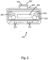
- Fig. 2 is an exemplary inside view of the bottom cap of Fig. 1 .
- Fig. 1 is an exemplary representation of a housing 10, an internal frame member 20, a strap 30, and an electrical connector 40 of a hand held computer terminal in an unassembled state.
- the hand held computer terminal illustrated in Fig. 1 is an image sensor based indicia reading terminal.
- This indicia reading terminal of Fig. 1 is exemplified herein throughout to illustrate and describe the apparatus and method of assembling the housing of a hand held computer terminal.
- One of ordinary skill in the art would recognize alternative types of hand held computer terminals for which the housing herein described would apply.
- the housing 10 can comprise a main body 100, a battery compartment door 200, a bottom cap 300, and a top cap 400.
- the main body 100 has a front side 102, a back side 104, a top side 105, and a bottom side 106.
- the front side 102 and the back side 104 can each be a separate piece fastened together to form a clamshell structure, or the front side 102 and the back side 104 can be one continuous piece forming a tube structure.
- the two-piece clamshell structure has a joint between the front side 102 and the back side 104, where pollutants can potentially ingress.
- the one-piece, tube structure is continuous between the front side 102 and the back side 104, and can better resist the ingress of pollutants between the front side 102 and the back side 104 of the main body 100 than the two-piece, clamshell structure.
- the one-piece, tube structure of the main body 100 can also be more resistant to physical impact than the two-piece structure of the main body 100.
- the main body 100 can define a bottom opening 116, a top opening 120, and a battery compartment opening 108.
- the top opening 120 can be assembled on the top side 105 of the main body 100.
- the top opening 120 can have a perimeter defined by top perimeter walls 122.
- the top perimeter walls can be relatively thin compared to the majority of the walls of the main body 100.
- the internal frame member 20 can be inserted into the main body 100 in an assembled state or removed from the main body 100 in a disassembled state.
- Fig. 1 shows the internal frame member partially inserted, or slid, into the main body 100.
- the internal frame member can be rigid or stiff, comprised of rigid or stiff material.
- the internal frame member 20 can be comprised of magnesium, a magnesium alloy, or another rigid material.
- the internal frame member 20 can be fastened to the housing 10.
- the internal frame member can comprise a plurality of fasteners to fasten the internal frame member 20 to the housing 10.
- the internal frame member 20 comprises top fastening holes 24 and bottom fastening holes 22. These fastening holes 22, 24 can be internally threaded to accept screws through the housing.
- the battery compartment opening 108 can be on the back side 104 of the main body 100.
- Other openings can be defined as well, such as a top opening 110, and other openings for extension of buttons, keys, and other features through the main body 100.
- the bottom opening 116 of the main body 100 can be on the bottom side 106 of the main body 100.
- the bottom opening 116 can have a perimeter defined by bottom perimeter walls 118.
- the bottom perimeter walls 118 can be relatively thin compared to the majority of the walls of the main body 100.
- the top cap 400 can be stronger than the main body 100, by comprising a stronger material, by comprising thicker walls, and/or by comprising reinforcing structures, such as reinforcement ridges 401, to add structural strength.
- the additional strength of the top cap 400 can protect the hand held computer terminal from physical shock, the type of which can occur when the hand held computer terminal is dropped. When the hand held computer terminal is dropped, the top or the bottom of the device is most likely to be directly impacted.
- the top cap 400 can have a top releasable fastener and a slot 408 extending around the inside surface of the top cap 400.
- the releasable fastener comprises top fastener holes 407.
- the top cap 400 can be assembled on the top side 105 of the main body 100 to cover the top opening 120. When the top cap 400 is assembled onto the main body 100, the top cap 400 can fit over the top opening 105 of the main body 100.
- the top perimeter walls 122 of the top opening 120 can fit into the slot 408 of the top cap 400.
- a relatively small or minimal clearance can be provided between the top perimeter walls 122 and the slot 408 of the top cap 400 to facilitate better sealing and a more secure fit.
- the outer surfaces of the main housing 100 and the outer surfaces of the top cap 400, at the joint between the main body 100 and the top cap 400, can substantially align to form a smooth seam.
- a top gasket 15 can be positioned between the top cap 400 and the main body 100 to seal the joint.
- the top gasket 15 can be a conventional gasket, such as a gasket made of rubber or plastic, or the top gasket 15 can be foamed into place.
- the top cap 400 can be tightened to the main body 100, for example, by driving screws through the top fastening holes 407 of the top cap 400 into top fastening holes 24 of the internal frame member 20.
- the battery compartment door 200 can be assembled and fastened with a releasable fastener on the back side 104 of the main body 100 to cover the battery compartment opening 108.
- the battery compartment door 200 is generally sized and shaped to match and correspond with the battery compartment opening 108.
- a bottom edge 220 of the battery compartment door can mate with the bottom cap 300.
- the battery compartment door 200 can comprise a bottom cap slot 216.
- the bottom cap slot 216 can be a cutout section at the bottom edge 220 of the battery compartment door 200.
- Fig. 2 is an exemplary inside view of the bottom cap 300 of Fig. 2 .
- the electrical connector 40 is shown mounted to the bottom cap 300.
- the bottom cap 300 can be assembled on the bottom side 106 of the main body 100 to cover the bottom opening 116.
- the bottom cap 300 can be stronger than the main body 100, by comprising a stronger material, by comprising thicker walls, and/or by comprising reinforcing structures, such as reinforcement ridges 301, to add structural strength.
- the additional strength of the bottom cap 300 can protect the hand held computer terminal from physical shock, the type of which can occur when the hand held computer terminal is dropped. When the hand held computer terminal is dropped, the top or the bottom of the device is most likely to be directly impacted.
- the bottom cap 300 can have a connector opening 302, a strap mount 304, and/or a bottom releasable fastener.
- the releasable fastener comprises bottom fastener holes 306.
- the bottom cap 300 can also have a slot 308 extending around the inside surface of the bottom cap 300.
- the electrical connector 40 can be fastened to the bottom cap 300 so that the electrical connector 40 extends through the connector opening 302 and/or faces outward from the bottom cap 300.
- the electrical connector 40 can be removably attached so that the electrical connector 40 can be removed from the electrical connector with access to the inside of the bottom cap 300. Otherwise, the electrical connector 40 can be permanently attached so that the bottom cap 300 would likely be discarded when replacing the electrical connector 40.
- the electrical connector 40 is soldered to the bottom cap 300.
- the strap mount 304 can be integral with the bottom cap 300 and can comprise, for example, a strap opening 310 through which the strap 30 can extend.
- the strap mount 304 can project from the bottom cap 300.
- the bottom cap 300 can comprise a back edge 303, wherein the strap mount 304 comprises a projection projecting from the back edge 303, and wherein the projection defines the strap opening 310 through the projection.
- the strap mount 304 can project into and fit within the bottom cap slot 216.
- the battery compartment door 200 can be isolated from the bottom cap 300, the main body 100 can comprise the bottom cap slot 216, and the strap mount 304 can project into and fit within the bottom cap slot 216 in the main body 100.
- the bottom cap 300 When the bottom cap 300 is assembled onto the main body 100, the bottom cap 300 can fit over the bottom opening 106 of the main body 100.
- the bottom perimeter walls 118 of the bottom opening 116 can fit into the slot 308.
- a relatively small or minimal clearance can be provided between the bottom perimeter walls 118 and the slot 308 to facilitate better sealing and a more secure fit.
- the outer surfaces of the main housing 100 and the outer surfaces of the bottom cap 300, at the joint between the main body 100 and the bottom cap 300, can substantially align to form a smooth seam.
- a bottom gasket 14 can be positioned between the bottom cap 300 and the main body 100 to seal the joint.
- the bottom gasket 14 can be a conventional gasket, such as a gasket made of rubber or plastic, or the bottom gasket 14 can be foamed into place.
- the bottom cap 300 can be tightened to the main body 100, for example, by driving screws through the fastening holes 306 into the main body 100 or another component internally connected to the main body 100.
- the internal frame member 20 can be positioned and/or fastened inside the main body 100, and the bottom cap 300 can be tightened to the main body 100 by driving screws through the bottom fastening holes 304 of the bottom cap 300 into the bottom fastening holes 22 of the internal frame member 20.
- the bottom fastening holes 22 of the internal frame member 20 can be internally threaded.
- Replacing the electrical connector 40 can be accomplished by unfastening the bottom cap 300, replacing the bottom cap 300 with another connector 40, and reassembling the bottom cap 300 to the main body 100 and/or the battery compartment door 200.
- the bottom cap 300 can be unfastened and replaced with a different bottom cap 300 and a different electrical connector 40. Replacing the bottom cap 300 is relatively inexpensive compared to replacing the front piece or the back piece of a two-piece clamshell style housing 10.
- Integrating the strap mount 304 as part of the bottom cap 300 is less cumbersome than mounting the strap to the back of the housing 10 using screws or ultrasonic welding. Additionally, the greater durability and strength of the bottom cap 300 relative to the main body 100 facilitates greater durability and strength withstanding forces imparted to the strap 30. Further, in the case that the strap mount 304 breaks, the bottom cap 300, can easily and cost efficiently be replaced, by unfastening the bottom cap 304, removing the bottom cap 304, and replacing the bottom cap 304, without replacing half the housing, as would be the case with a two-piece clam-shell style housing.
- the apparatus disclosed herein can be applied to a variety of hand held terminals, such as scanners, digital cameras, cell phones, and mobile computers.
Landscapes
- Engineering & Computer Science (AREA)
- Computer Hardware Design (AREA)
- Theoretical Computer Science (AREA)
- General Engineering & Computer Science (AREA)
- Human Computer Interaction (AREA)
- Physics & Mathematics (AREA)
- General Physics & Mathematics (AREA)
- Casings For Electric Apparatus (AREA)
Description
- The present invention relates to a hand held computer terminal in general and specifically to an assembly of a housing of a hand held computer terminal.
- Hand held computer terminals can be used for a variety of purposes. Indicia reading terminals, for example, have been used for a number of years in industrial data collection applications and for purposes of decoding information encoded in bar code symbols. Many hand held computer terminals, such as indicia reading terminals, are multifunctional and/or have broad computing capabilities. The computational functionalities of hand held computer terminals are enabled by electronic components and other hardware.
- The packaging of these electronic components into a housing of hand held computer terminal can be complex, with many factors influencing the housing design. For instance, the hand held computer terminal can be designed to prevent ingress of external pollutants, increase ergonomic function, increase durability, increase accessibility, and decrease manufacturing and repair costs.
- The internal electronic components can be damaged by external pollutants, such as water, dirt, dust, or other debris. When water ingresses the housing, the water is likely to cause electrical shorts, corrosion, or other damage. Electrical shorts can cause temporary or permanent malfunctions. Corrosion and other physical damage can also cause permanent malfunctions. Likewise, while sometimes less intrusive, dirt, dust, or other debris can be problematic, causing problems ranging from a nuisance to severe damage.
- Ergonomics and durability also influence the design. As a hand held device, hand held computer terminals can be considered more desirable to use when fitted comfortably in a hand. A hand strap can make it easier to hold the hand held computer terminal, and less likely to drop the hand held computer terminal, especially when the hand held computer terminal is held for longer periods of time. Resistance to damage from physical impact is beneficial, as well, for example, when the hand held computer terminal is mishandled or dropped.
- The accessibility of the hand held computer terminal to repair defective or broken parts, or to otherwise assemble, disassemble, and/or reassemble the hand held computer terminal can also influence the design. Efficient assembly, disassembly, and/or reassembly can lower manufacturing or repair costs and save time.
- Optimizing one factor in the mechanical design of a hand held computer terminal can diminish the optimization of another factor, making it a complex matter to configure the mechanical design of a hand held computer terminal for balanced efficiency and/or overall optimization, wherein the hand held computer terminal is well sealed, durable, ergonomically efficient, and easily repairable, all while being cost efficient to manufacture or repair.
- In one method of packaging the components, a clamshell style housing has a front housing member and a back housing member that are fastened together to enclose the electronic components. A hand strap can be mounted as a separate piece screwed or ultrasonically welded to the back housing member. This design is cumbersome and costly. Further, repair and/or replacement of some components requires labor intensive processes and discarding of expensive parts. For instance, with the clamshell style housing, an electrical connector (e.g., a charge/communication connector) located at the bottom of the hand held computer terminal is mounted to the front housing member or the back housing member. The front housing member and the back housing member must be dismantled to access and replace the electrical connector. The electrical connector is soldered to the housing member, so the electrical connector is often removed and re-soldered to a replacement housing member, while the removed housing member is discarded.
-
US 502 3824 discloses a hand-held computerised data collection terminal with indented and grip and conforming battery drawer. -
US 7 344 083 discloses a hand held device having a housing with a main body and comprising a bottom cap fitting over an opening provided at the bottom of the main body to cover the opening, wherein the bottom cap comprises a strap mount for attaching a hand strap. - It would be useful to have a hand held computer terminal that cost efficiently facilitates sealing, durability, ergonomics, and accessibility, and reduces or avoids the problems identified herein above.
- The present invention in its various aspects is as set out in the appended claims.
- According to the features of claim 1, a hand held computer terminal comprises a housing. The housing comprises a main body, a top cap, and a bottom cap. The main body comprises a front side and a back side, a top opening, and a bottom opening. The top cap fits over the top opening to cover the top opening of the main body. The bottom cap fits over the bottom opening to cover the bottom opening of the main body. The bottom cap comprises a strap mount for attaching a hand strap, and an electrical connector opening for mounting an electrical connector.
- The features described herein can be better understood with reference to the drawings described below. The drawings are not necessarily to scale, emphasis instead generally being placed upon illustrating the principles of the invention. In the drawings, like numerals are used to indicate like parts throughout the various views.
-
Fig. 1 is an exemplary isometric representation of a housing, an internal frame member, and a hand strap of a hand held computer terminal in an unassembled state, in one embodiment. -
Fig. 2 is an exemplary inside view of the bottom cap ofFig. 1 . -
Fig. 1 is an exemplary representation of ahousing 10, aninternal frame member 20, astrap 30, and anelectrical connector 40 of a hand held computer terminal in an unassembled state. The hand held computer terminal illustrated inFig. 1 is an image sensor based indicia reading terminal. This indicia reading terminal ofFig. 1 is exemplified herein throughout to illustrate and describe the apparatus and method of assembling the housing of a hand held computer terminal. One of ordinary skill in the art would recognize alternative types of hand held computer terminals for which the housing herein described would apply. - Referring to
Fig. 1 , thehousing 10 can comprise amain body 100, abattery compartment door 200, abottom cap 300, and atop cap 400. Themain body 100 has afront side 102, aback side 104, atop side 105, and abottom side 106. Thefront side 102 and theback side 104 can each be a separate piece fastened together to form a clamshell structure, or thefront side 102 and theback side 104 can be one continuous piece forming a tube structure. The two-piece clamshell structure has a joint between thefront side 102 and theback side 104, where pollutants can potentially ingress. The one-piece, tube structure is continuous between thefront side 102 and theback side 104, and can better resist the ingress of pollutants between thefront side 102 and theback side 104 of themain body 100 than the two-piece, clamshell structure. The one-piece, tube structure of themain body 100 can also be more resistant to physical impact than the two-piece structure of themain body 100. - The
main body 100 can define a bottom opening 116, a top opening 120, and a battery compartment opening 108. The top opening 120 can be assembled on thetop side 105 of themain body 100. The top opening 120 can have a perimeter defined bytop perimeter walls 122. The top perimeter walls can be relatively thin compared to the majority of the walls of themain body 100. - The
internal frame member 20 can be inserted into themain body 100 in an assembled state or removed from themain body 100 in a disassembled state.Fig. 1 shows the internal frame member partially inserted, or slid, into themain body 100. The internal frame member can be rigid or stiff, comprised of rigid or stiff material. For example, theinternal frame member 20 can be comprised of magnesium, a magnesium alloy, or another rigid material. When assembled with thehousing 10, theinternal frame member 20 can be fastened to thehousing 10. For example, the internal frame member can comprise a plurality of fasteners to fasten theinternal frame member 20 to thehousing 10. In the illustrated embodiment, theinternal frame member 20 comprises top fastening holes 24 and bottom fastening holes 22. These fastening holes 22, 24 can be internally threaded to accept screws through the housing. - The battery compartment opening 108 can be on the
back side 104 of themain body 100. Other openings can be defined as well, such as a top opening 110, and other openings for extension of buttons, keys, and other features through themain body 100. - The
bottom opening 116 of themain body 100 can be on thebottom side 106 of themain body 100. Thebottom opening 116 can have a perimeter defined bybottom perimeter walls 118. Thebottom perimeter walls 118 can be relatively thin compared to the majority of the walls of themain body 100. - The
top cap 400 can be stronger than themain body 100, by comprising a stronger material, by comprising thicker walls, and/or by comprising reinforcing structures, such asreinforcement ridges 401, to add structural strength. The additional strength of thetop cap 400 can protect the hand held computer terminal from physical shock, the type of which can occur when the hand held computer terminal is dropped. When the hand held computer terminal is dropped, the top or the bottom of the device is most likely to be directly impacted. - The
top cap 400 can have a top releasable fastener and aslot 408 extending around the inside surface of thetop cap 400. In the illustrated embodiment, the releasable fastener comprises top fastener holes 407. Thetop cap 400 can be assembled on thetop side 105 of themain body 100 to cover thetop opening 120. When thetop cap 400 is assembled onto themain body 100, thetop cap 400 can fit over thetop opening 105 of themain body 100. For example, thetop perimeter walls 122 of thetop opening 120 can fit into theslot 408 of thetop cap 400. A relatively small or minimal clearance can be provided between thetop perimeter walls 122 and theslot 408 of thetop cap 400 to facilitate better sealing and a more secure fit. The outer surfaces of themain housing 100 and the outer surfaces of thetop cap 400, at the joint between themain body 100 and thetop cap 400, can substantially align to form a smooth seam. Atop gasket 15 can be positioned between thetop cap 400 and themain body 100 to seal the joint. Thetop gasket 15 can be a conventional gasket, such as a gasket made of rubber or plastic, or thetop gasket 15 can be foamed into place. Thetop cap 400 can be tightened to themain body 100, for example, by driving screws through thetop fastening holes 407 of thetop cap 400 into top fastening holes 24 of theinternal frame member 20. - The
battery compartment door 200 can be assembled and fastened with a releasable fastener on theback side 104 of themain body 100 to cover thebattery compartment opening 108. Thebattery compartment door 200 is generally sized and shaped to match and correspond with thebattery compartment opening 108. Abottom edge 220 of the battery compartment door can mate with thebottom cap 300. Thebattery compartment door 200 can comprise abottom cap slot 216. Thebottom cap slot 216 can be a cutout section at thebottom edge 220 of thebattery compartment door 200. -
Fig. 2 is an exemplary inside view of thebottom cap 300 ofFig. 2 . Theelectrical connector 40 is shown mounted to thebottom cap 300. Referring toFig. 1 andFig. 2 , thebottom cap 300 can be assembled on thebottom side 106 of themain body 100 to cover thebottom opening 116. Thebottom cap 300 can be stronger than themain body 100, by comprising a stronger material, by comprising thicker walls, and/or by comprising reinforcing structures, such asreinforcement ridges 301, to add structural strength. The additional strength of thebottom cap 300 can protect the hand held computer terminal from physical shock, the type of which can occur when the hand held computer terminal is dropped. When the hand held computer terminal is dropped, the top or the bottom of the device is most likely to be directly impacted. - The
bottom cap 300 can have aconnector opening 302, astrap mount 304, and/or a bottom releasable fastener. In the illustrated example, the releasable fastener comprises bottom fastener holes 306. Thebottom cap 300 can also have aslot 308 extending around the inside surface of thebottom cap 300. - The
electrical connector 40 can be fastened to thebottom cap 300 so that theelectrical connector 40 extends through theconnector opening 302 and/or faces outward from thebottom cap 300. Theelectrical connector 40 can be removably attached so that theelectrical connector 40 can be removed from the electrical connector with access to the inside of thebottom cap 300. Otherwise, theelectrical connector 40 can be permanently attached so that thebottom cap 300 would likely be discarded when replacing theelectrical connector 40. In one example, theelectrical connector 40 is soldered to thebottom cap 300. - The
strap mount 304 can be integral with thebottom cap 300 and can comprise, for example, astrap opening 310 through which thestrap 30 can extend. In one embodiment, thestrap mount 304 can project from thebottom cap 300. Thebottom cap 300 can comprise aback edge 303, wherein thestrap mount 304 comprises a projection projecting from theback edge 303, and wherein the projection defines thestrap opening 310 through the projection. When assembled with thebattery compartment door 200 and themain body 100, thestrap mount 304 can project into and fit within thebottom cap slot 216. In another alternative, thebattery compartment door 200 can be isolated from thebottom cap 300, themain body 100 can comprise thebottom cap slot 216, and thestrap mount 304 can project into and fit within thebottom cap slot 216 in themain body 100. - When the
bottom cap 300 is assembled onto themain body 100, thebottom cap 300 can fit over thebottom opening 106 of themain body 100. For example, thebottom perimeter walls 118 of thebottom opening 116 can fit into theslot 308. A relatively small or minimal clearance can be provided between thebottom perimeter walls 118 and theslot 308 to facilitate better sealing and a more secure fit. The outer surfaces of themain housing 100 and the outer surfaces of thebottom cap 300, at the joint between themain body 100 and thebottom cap 300, can substantially align to form a smooth seam. A bottom gasket 14 can be positioned between thebottom cap 300 and themain body 100 to seal the joint. The bottom gasket 14 can be a conventional gasket, such as a gasket made of rubber or plastic, or the bottom gasket 14 can be foamed into place. - The
bottom cap 300 can be tightened to themain body 100, for example, by driving screws through the fastening holes 306 into themain body 100 or another component internally connected to themain body 100. In one embodiment, theinternal frame member 20 can be positioned and/or fastened inside themain body 100, and thebottom cap 300 can be tightened to themain body 100 by driving screws through the bottom fastening holes 304 of thebottom cap 300 into the bottom fastening holes 22 of theinternal frame member 20. The bottom fastening holes 22 of theinternal frame member 20 can be internally threaded. - Replacing the
electrical connector 40 can be accomplished by unfastening thebottom cap 300, replacing thebottom cap 300 with anotherconnector 40, and reassembling thebottom cap 300 to themain body 100 and/or thebattery compartment door 200. In some embodiments, thebottom cap 300 can be unfastened and replaced with a differentbottom cap 300 and a differentelectrical connector 40. Replacing thebottom cap 300 is relatively inexpensive compared to replacing the front piece or the back piece of a two-piececlamshell style housing 10. - Integrating the
strap mount 304 as part of thebottom cap 300 is less cumbersome than mounting the strap to the back of thehousing 10 using screws or ultrasonic welding. Additionally, the greater durability and strength of thebottom cap 300 relative to themain body 100 facilitates greater durability and strength withstanding forces imparted to thestrap 30. Further, in the case that thestrap mount 304 breaks, thebottom cap 300, can easily and cost efficiently be replaced, by unfastening thebottom cap 304, removing thebottom cap 304, and replacing thebottom cap 304, without replacing half the housing, as would be the case with a two-piece clam-shell style housing. - It will be appreciated that the apparatus disclosed herein can be applied to a variety of hand held terminals, such as scanners, digital cameras, cell phones, and mobile computers.
- While the present invention has been described with reference to a number of specific embodiments, it will be understood that the scope of the invention should be determined only with respect to the following claims.
Claims (14)
- A hand held computer terminal comprising:a housing (10) comprising a main body (100), a top cap (400), and a bottom cap (300),wherein the main body (100) of the housing (10) comprises a front side (102) and a back side (104), a top opening (120), and a bottom opening (116),wherein the top cap (400) fits over the top opening (120) to cover the top opening (120) of the main body (100),wherein the bottom cap (300) fits over the bottom opening (116) to cover the bottom opening (116) of the main body (100),wherein the bottom cap (300) comprises a strap mount (304) for attaching a hand strap (30), andwherein the bottom cap (300) comprises an electrical connector opening (302) for mounting an electrical connector (40).
- The hand held computer terminal of claim 1, wherein the hand held computer terminal comprises an internal frame member (20) inserted within the main body (100) of the housing (10), wherein the top cap (300) is fastened to the internal frame member (20), and wherein the bottom cap (300) is fastened to the internal frame member (20).
- The hand held computer terminal of claim 1, wherein the bottom cap (300) has an outside surface and an inside surface, wherein the inside surface comprises a slot (308) engageable with the bottom of the main body (100) of the housing (10).
- The hand held computer terminal of claim 1, wherein the strap mount (304) is an opening (310) defined through the bottom cap (300).
- The hand held computer terminal of claim 1, wherein the bottom cap (300) comprises a back edge (303), wherein the strap mount (304) comprises a projection projecting from the back edge, and wherein the projection defines an opening through the projection.
- The hand held computer terminal of claim 5, wherein the main body (100) further comprises a battery compartment opening (108), wherein the hand held computer terminal further comprises a battery compartment door (200), wherein the battery compartment door (200) fits over the battery compartment opening (108) and comprises a bottom edge (220), wherein the battery compartment door (200) comprises a cutout slot (216) on the bottom edge (220), and wherein the strap mount (304) matingly fits into the cutout slot (216).
- The hand held computer terminal of claim 1, further comprising a bottom seal (14) positioned between the bottom cap (300) and the main body (100) to seal the joint between the bottom cap (300) and the main body (100).
- The hand held computer terminal of claim 1, further comprising a top seal (15) positioned between the top cap (400) and the main body (100) to seal the joint between the top cap (400) and the main body (100).
- The hand held computer terminal of claim 1, wherein the bottom cap (300) is more resistant to physical impact than the main body (100).
- The hand held computer terminal of claim 1, wherein the bottom cap (300) comprises a releasable fastener (306) to releasably fasten the bottom cap (300) to a main body (100) of the housing (10) of the hand held computer terminal.
- The hand held computer terminal of claim 1, wherein the strap mount (304) is integral with the bottom cap (300).
- The hand held computer terminal of claim 1, wherein the main body (100) of the housing (10) is one contiguous piece forming a tube structure.
- The hand held computer terminal of claim 1, wherein the bottom cap (300) includes an electrical connector (40) removably attached thereto.
- The hand held computer terminal of claim 1, wherein the bottom cap (300) includes an electrical connector (40) permanently attached thereto.
Applications Claiming Priority (1)
| Application Number | Priority Date | Filing Date | Title |
|---|---|---|---|
| US13/169,505 US8614883B2 (en) | 2011-06-27 | 2011-06-27 | Assembly of a hand held computer terminal housing |
Publications (2)
| Publication Number | Publication Date |
|---|---|
| EP2541369A1 EP2541369A1 (en) | 2013-01-02 |
| EP2541369B1 true EP2541369B1 (en) | 2020-05-20 |
Family
ID=46545617
Family Applications (1)
| Application Number | Title | Priority Date | Filing Date |
|---|---|---|---|
| EP12172839.8A Active EP2541369B1 (en) | 2011-06-27 | 2012-06-20 | Assembly of a hand held computer terminal housing |
Country Status (3)
| Country | Link |
|---|---|
| US (1) | US8614883B2 (en) |
| EP (1) | EP2541369B1 (en) |
| CN (2) | CN102866731A (en) |
Families Citing this family (3)
| Publication number | Priority date | Publication date | Assignee | Title |
|---|---|---|---|---|
| US8763909B2 (en) * | 2011-01-04 | 2014-07-01 | Hand Held Products, Inc. | Terminal comprising mount for supporting a mechanical component |
| JP6394949B2 (en) * | 2014-09-08 | 2018-09-26 | カシオ計算機株式会社 | Belt mounting structure and electronic equipment |
| USD868066S1 (en) * | 2017-09-14 | 2019-11-26 | Hand Held Products, Inc. | Handheld electronic device |
Citations (1)
| Publication number | Priority date | Publication date | Assignee | Title |
|---|---|---|---|---|
| US7344083B1 (en) * | 2005-08-31 | 2008-03-18 | Hand Held Products, Inc. | Strap clip |
Family Cites Families (14)
| Publication number | Priority date | Publication date | Assignee | Title |
|---|---|---|---|---|
| US5023824A (en) | 1987-10-02 | 1991-06-11 | Norand Corporation | Hand-held computerized data collection terminal with indented hand grip and conforming battery drawer |
| US5805416A (en) | 1995-09-11 | 1998-09-08 | Norand Corporation | Modular hand-held data capture terminal |
| JPH1091281A (en) * | 1996-08-19 | 1998-04-10 | Internatl Business Mach Corp <Ibm> | Information processing equipment |
| US6837435B2 (en) * | 1997-06-26 | 2005-01-04 | Symbol Technologies, Inc. | Adapter unit having a handle grip for a personal digital assistant |
| JP2002134934A (en) * | 2000-10-30 | 2002-05-10 | Matsushita Electric Ind Co Ltd | Strap fixing structure for mobile communication equipment |
| US6724618B1 (en) | 2001-08-09 | 2004-04-20 | Symbol Technologies, Inc. | Housing for a portable electronic device |
| CN1671150A (en) * | 2003-08-15 | 2005-09-21 | 张逶 | A microminiature keypad or handset and method |
| JP3100170U (en) * | 2003-08-29 | 2004-04-30 | 株式会社レモン社 | Bottom cover detachable camera strap |
| US7446753B2 (en) | 2004-09-10 | 2008-11-04 | Hand Held Products, Inc. | Hand held computer device |
| JP2006093328A (en) * | 2004-09-22 | 2006-04-06 | Mitsubishi Electric Corp | Portable device |
| JP5017566B2 (en) * | 2006-08-21 | 2012-09-05 | ソニーモバイルコミュニケーションズ, エービー | Strap mounting device for portable terminal device and strap mounting method for portable terminal device |
| JP2008191377A (en) * | 2007-02-05 | 2008-08-21 | Olympus Corp | Portable electronic equipment |
| US8004835B2 (en) | 2007-12-27 | 2011-08-23 | Hand Held Products, Inc. | Portable data terminal internal support structure |
| US9158340B2 (en) * | 2011-06-27 | 2015-10-13 | Hand Held Products, Inc. | Apparatus and method for assembling display of indicia reading terminal |
-
2011
- 2011-06-27 US US13/169,505 patent/US8614883B2/en active Active
-
2012
- 2012-06-20 EP EP12172839.8A patent/EP2541369B1/en active Active
- 2012-06-26 CN CN2012102755971A patent/CN102866731A/en active Pending
- 2012-06-26 CN CN201910700889.7A patent/CN110333759A/en active Pending
Patent Citations (1)
| Publication number | Priority date | Publication date | Assignee | Title |
|---|---|---|---|---|
| US7344083B1 (en) * | 2005-08-31 | 2008-03-18 | Hand Held Products, Inc. | Strap clip |
Also Published As
| Publication number | Publication date |
|---|---|
| US8614883B2 (en) | 2013-12-24 |
| US20120327577A1 (en) | 2012-12-27 |
| CN102866731A (en) | 2013-01-09 |
| CN110333759A (en) | 2019-10-15 |
| EP2541369A1 (en) | 2013-01-02 |
Similar Documents
| Publication | Publication Date | Title |
|---|---|---|
| US9612618B2 (en) | Apparatus and method for assembling display of indicia reading terminal | |
| US20100203924A1 (en) | Electronic Device and Mobile Phone | |
| CN101689336B (en) | Opening/closing display device | |
| CN101685849B (en) | Locking structure for battery cover | |
| US8199466B2 (en) | Housing assembly for a portable electronic device | |
| EP2571231B1 (en) | Cushion for a folding handheld electronic device and waterproofing structure for a folding handheld electronic device | |
| US8614883B2 (en) | Assembly of a hand held computer terminal housing | |
| US8251408B2 (en) | Battery cover latch mechanism and portable electronic device using same | |
| US20100151304A1 (en) | Battery cover latching assembly | |
| AU2010202301A1 (en) | Torque cell | |
| WO2016063766A1 (en) | Outdoor unit for air conditioner | |
| US7983036B2 (en) | Flexible sheet with sealing skirt for keyboard assembly | |
| KR101966256B1 (en) | Assembling structure of housing for portable terminal | |
| JP4875650B2 (en) | Display device for portable terminal and portable terminal equipped with the display device | |
| JP5010107B2 (en) | Structure for attaching terminal cover to electronic device and mobile phone | |
| CN218092524U (en) | Automobile remote control key protection structure | |
| CN105513868A (en) | Mechanical keyboard | |
| CN211416755U (en) | Frame structure of electronic whiteboard | |
| US20240405792A1 (en) | Two-Piece Exoskeleton for a Mobile Computing Device | |
| KR101417802B1 (en) | Battery cover opening/closing device for electronic appliances | |
| JP5512351B2 (en) | Member storage device | |
| KR101758683B1 (en) | Case for installing electronic components | |
| JP2014120881A (en) | Mobile device | |
| JP4892739B2 (en) | Foldable electronics | |
| JP6193606B2 (en) | Mobile device |
Legal Events
| Date | Code | Title | Description |
|---|---|---|---|
| PUAI | Public reference made under article 153(3) epc to a published international application that has entered the european phase |
Free format text: ORIGINAL CODE: 0009012 |
|
| 17P | Request for examination filed |
Effective date: 20120620 |
|
| AK | Designated contracting states |
Kind code of ref document: A1 Designated state(s): AL AT BE BG CH CY CZ DE DK EE ES FI FR GB GR HR HU IE IS IT LI LT LU LV MC MK MT NL NO PL PT RO RS SE SI SK SM TR |
|
| AX | Request for extension of the european patent |
Extension state: BA ME |
|
| STAA | Information on the status of an ep patent application or granted ep patent |
Free format text: STATUS: EXAMINATION IS IN PROGRESS |
|
| GRAP | Despatch of communication of intention to grant a patent |
Free format text: ORIGINAL CODE: EPIDOSNIGR1 |
|
| STAA | Information on the status of an ep patent application or granted ep patent |
Free format text: STATUS: GRANT OF PATENT IS INTENDED |
|
| INTG | Intention to grant announced |
Effective date: 20191218 |
|
| GRAS | Grant fee paid |
Free format text: ORIGINAL CODE: EPIDOSNIGR3 |
|
| GRAA | (expected) grant |
Free format text: ORIGINAL CODE: 0009210 |
|
| STAA | Information on the status of an ep patent application or granted ep patent |
Free format text: STATUS: THE PATENT HAS BEEN GRANTED |
|
| AK | Designated contracting states |
Kind code of ref document: B1 Designated state(s): AL AT BE BG CH CY CZ DE DK EE ES FI FR GB GR HR HU IE IS IT LI LT LU LV MC MK MT NL NO PL PT RO RS SE SI SK SM TR |
|
| REG | Reference to a national code |
Ref country code: GB Ref legal event code: FG4D |
|
| REG | Reference to a national code |
Ref country code: CH Ref legal event code: EP |
|
| REG | Reference to a national code |
Ref country code: DE Ref legal event code: R096 Ref document number: 602012070181 Country of ref document: DE |
|
| REG | Reference to a national code |
Ref country code: AT Ref legal event code: REF Ref document number: 1273012 Country of ref document: AT Kind code of ref document: T Effective date: 20200615 |
|
| REG | Reference to a national code |
Ref country code: LT Ref legal event code: MG4D |
|
| REG | Reference to a national code |
Ref country code: NL Ref legal event code: MP Effective date: 20200520 |
|
| PG25 | Lapsed in a contracting state [announced via postgrant information from national office to epo] |
Ref country code: IS Free format text: LAPSE BECAUSE OF FAILURE TO SUBMIT A TRANSLATION OF THE DESCRIPTION OR TO PAY THE FEE WITHIN THE PRESCRIBED TIME-LIMIT Effective date: 20200920 Ref country code: SE Free format text: LAPSE BECAUSE OF FAILURE TO SUBMIT A TRANSLATION OF THE DESCRIPTION OR TO PAY THE FEE WITHIN THE PRESCRIBED TIME-LIMIT Effective date: 20200520 Ref country code: NO Free format text: LAPSE BECAUSE OF FAILURE TO SUBMIT A TRANSLATION OF THE DESCRIPTION OR TO PAY THE FEE WITHIN THE PRESCRIBED TIME-LIMIT Effective date: 20200820 Ref country code: PT Free format text: LAPSE BECAUSE OF FAILURE TO SUBMIT A TRANSLATION OF THE DESCRIPTION OR TO PAY THE FEE WITHIN THE PRESCRIBED TIME-LIMIT Effective date: 20200921 Ref country code: FI Free format text: LAPSE BECAUSE OF FAILURE TO SUBMIT A TRANSLATION OF THE DESCRIPTION OR TO PAY THE FEE WITHIN THE PRESCRIBED TIME-LIMIT Effective date: 20200520 Ref country code: GR Free format text: LAPSE BECAUSE OF FAILURE TO SUBMIT A TRANSLATION OF THE DESCRIPTION OR TO PAY THE FEE WITHIN THE PRESCRIBED TIME-LIMIT Effective date: 20200821 Ref country code: LT Free format text: LAPSE BECAUSE OF FAILURE TO SUBMIT A TRANSLATION OF THE DESCRIPTION OR TO PAY THE FEE WITHIN THE PRESCRIBED TIME-LIMIT Effective date: 20200520 |
|
| PG25 | Lapsed in a contracting state [announced via postgrant information from national office to epo] |
Ref country code: LV Free format text: LAPSE BECAUSE OF FAILURE TO SUBMIT A TRANSLATION OF THE DESCRIPTION OR TO PAY THE FEE WITHIN THE PRESCRIBED TIME-LIMIT Effective date: 20200520 Ref country code: HR Free format text: LAPSE BECAUSE OF FAILURE TO SUBMIT A TRANSLATION OF THE DESCRIPTION OR TO PAY THE FEE WITHIN THE PRESCRIBED TIME-LIMIT Effective date: 20200520 Ref country code: RS Free format text: LAPSE BECAUSE OF FAILURE TO SUBMIT A TRANSLATION OF THE DESCRIPTION OR TO PAY THE FEE WITHIN THE PRESCRIBED TIME-LIMIT Effective date: 20200520 Ref country code: BG Free format text: LAPSE BECAUSE OF FAILURE TO SUBMIT A TRANSLATION OF THE DESCRIPTION OR TO PAY THE FEE WITHIN THE PRESCRIBED TIME-LIMIT Effective date: 20200820 |
|
| REG | Reference to a national code |
Ref country code: AT Ref legal event code: MK05 Ref document number: 1273012 Country of ref document: AT Kind code of ref document: T Effective date: 20200520 |
|
| PG25 | Lapsed in a contracting state [announced via postgrant information from national office to epo] |
Ref country code: AL Free format text: LAPSE BECAUSE OF FAILURE TO SUBMIT A TRANSLATION OF THE DESCRIPTION OR TO PAY THE FEE WITHIN THE PRESCRIBED TIME-LIMIT Effective date: 20200520 Ref country code: NL Free format text: LAPSE BECAUSE OF FAILURE TO SUBMIT A TRANSLATION OF THE DESCRIPTION OR TO PAY THE FEE WITHIN THE PRESCRIBED TIME-LIMIT Effective date: 20200520 |
|
| PG25 | Lapsed in a contracting state [announced via postgrant information from national office to epo] |
Ref country code: AT Free format text: LAPSE BECAUSE OF FAILURE TO SUBMIT A TRANSLATION OF THE DESCRIPTION OR TO PAY THE FEE WITHIN THE PRESCRIBED TIME-LIMIT Effective date: 20200520 Ref country code: DK Free format text: LAPSE BECAUSE OF FAILURE TO SUBMIT A TRANSLATION OF THE DESCRIPTION OR TO PAY THE FEE WITHIN THE PRESCRIBED TIME-LIMIT Effective date: 20200520 Ref country code: ES Free format text: LAPSE BECAUSE OF FAILURE TO SUBMIT A TRANSLATION OF THE DESCRIPTION OR TO PAY THE FEE WITHIN THE PRESCRIBED TIME-LIMIT Effective date: 20200520 Ref country code: CZ Free format text: LAPSE BECAUSE OF FAILURE TO SUBMIT A TRANSLATION OF THE DESCRIPTION OR TO PAY THE FEE WITHIN THE PRESCRIBED TIME-LIMIT Effective date: 20200520 Ref country code: RO Free format text: LAPSE BECAUSE OF FAILURE TO SUBMIT A TRANSLATION OF THE DESCRIPTION OR TO PAY THE FEE WITHIN THE PRESCRIBED TIME-LIMIT Effective date: 20200520 Ref country code: EE Free format text: LAPSE BECAUSE OF FAILURE TO SUBMIT A TRANSLATION OF THE DESCRIPTION OR TO PAY THE FEE WITHIN THE PRESCRIBED TIME-LIMIT Effective date: 20200520 Ref country code: SM Free format text: LAPSE BECAUSE OF FAILURE TO SUBMIT A TRANSLATION OF THE DESCRIPTION OR TO PAY THE FEE WITHIN THE PRESCRIBED TIME-LIMIT Effective date: 20200520 Ref country code: IT Free format text: LAPSE BECAUSE OF FAILURE TO SUBMIT A TRANSLATION OF THE DESCRIPTION OR TO PAY THE FEE WITHIN THE PRESCRIBED TIME-LIMIT Effective date: 20200520 |
|
| REG | Reference to a national code |
Ref country code: CH Ref legal event code: PL |
|
| REG | Reference to a national code |
Ref country code: DE Ref legal event code: R097 Ref document number: 602012070181 Country of ref document: DE |
|
| PG25 | Lapsed in a contracting state [announced via postgrant information from national office to epo] |
Ref country code: PL Free format text: LAPSE BECAUSE OF FAILURE TO SUBMIT A TRANSLATION OF THE DESCRIPTION OR TO PAY THE FEE WITHIN THE PRESCRIBED TIME-LIMIT Effective date: 20200520 Ref country code: MC Free format text: LAPSE BECAUSE OF FAILURE TO SUBMIT A TRANSLATION OF THE DESCRIPTION OR TO PAY THE FEE WITHIN THE PRESCRIBED TIME-LIMIT Effective date: 20200520 Ref country code: SK Free format text: LAPSE BECAUSE OF FAILURE TO SUBMIT A TRANSLATION OF THE DESCRIPTION OR TO PAY THE FEE WITHIN THE PRESCRIBED TIME-LIMIT Effective date: 20200520 |
|
| PLBE | No opposition filed within time limit |
Free format text: ORIGINAL CODE: 0009261 |
|
| STAA | Information on the status of an ep patent application or granted ep patent |
Free format text: STATUS: NO OPPOSITION FILED WITHIN TIME LIMIT |
|
| PG25 | Lapsed in a contracting state [announced via postgrant information from national office to epo] |
Ref country code: LU Free format text: LAPSE BECAUSE OF NON-PAYMENT OF DUE FEES Effective date: 20200620 |
|
| REG | Reference to a national code |
Ref country code: BE Ref legal event code: MM Effective date: 20200630 |
|
| 26N | No opposition filed |
Effective date: 20210223 |
|
| PG25 | Lapsed in a contracting state [announced via postgrant information from national office to epo] |
Ref country code: CH Free format text: LAPSE BECAUSE OF NON-PAYMENT OF DUE FEES Effective date: 20200630 Ref country code: LI Free format text: LAPSE BECAUSE OF NON-PAYMENT OF DUE FEES Effective date: 20200630 Ref country code: IE Free format text: LAPSE BECAUSE OF NON-PAYMENT OF DUE FEES Effective date: 20200620 |
|
| PG25 | Lapsed in a contracting state [announced via postgrant information from national office to epo] |
Ref country code: SI Free format text: LAPSE BECAUSE OF FAILURE TO SUBMIT A TRANSLATION OF THE DESCRIPTION OR TO PAY THE FEE WITHIN THE PRESCRIBED TIME-LIMIT Effective date: 20200520 Ref country code: BE Free format text: LAPSE BECAUSE OF NON-PAYMENT OF DUE FEES Effective date: 20200630 |
|
| PG25 | Lapsed in a contracting state [announced via postgrant information from national office to epo] |
Ref country code: TR Free format text: LAPSE BECAUSE OF FAILURE TO SUBMIT A TRANSLATION OF THE DESCRIPTION OR TO PAY THE FEE WITHIN THE PRESCRIBED TIME-LIMIT Effective date: 20200520 Ref country code: MT Free format text: LAPSE BECAUSE OF FAILURE TO SUBMIT A TRANSLATION OF THE DESCRIPTION OR TO PAY THE FEE WITHIN THE PRESCRIBED TIME-LIMIT Effective date: 20200520 Ref country code: CY Free format text: LAPSE BECAUSE OF FAILURE TO SUBMIT A TRANSLATION OF THE DESCRIPTION OR TO PAY THE FEE WITHIN THE PRESCRIBED TIME-LIMIT Effective date: 20200520 |
|
| PG25 | Lapsed in a contracting state [announced via postgrant information from national office to epo] |
Ref country code: MK Free format text: LAPSE BECAUSE OF FAILURE TO SUBMIT A TRANSLATION OF THE DESCRIPTION OR TO PAY THE FEE WITHIN THE PRESCRIBED TIME-LIMIT Effective date: 20200520 |
|
| PGFP | Annual fee paid to national office [announced via postgrant information from national office to epo] |
Ref country code: FR Payment date: 20240625 Year of fee payment: 13 |
|
| PG25 | Lapsed in a contracting state [announced via postgrant information from national office to epo] |
Ref country code: FR Free format text: LAPSE BECAUSE OF NON-PAYMENT OF DUE FEES Effective date: 20250630 |
|
| PGFP | Annual fee paid to national office [announced via postgrant information from national office to epo] |
Ref country code: GB Payment date: 20260622 Year of fee payment: 15 |
|
| PGFP | Annual fee paid to national office [announced via postgrant information from national office to epo] |
Ref country code: DE Payment date: 20260623 Year of fee payment: 15 |