EP2541231A1 - Hydrogen content ratio acquiring apparatus and hydrogen content ratio acquiring method - Google Patents
Hydrogen content ratio acquiring apparatus and hydrogen content ratio acquiring method Download PDFInfo
- Publication number
- EP2541231A1 EP2541231A1 EP11747216A EP11747216A EP2541231A1 EP 2541231 A1 EP2541231 A1 EP 2541231A1 EP 11747216 A EP11747216 A EP 11747216A EP 11747216 A EP11747216 A EP 11747216A EP 2541231 A1 EP2541231 A1 EP 2541231A1
- Authority
- EP
- European Patent Office
- Prior art keywords
- sih
- silicon film
- shift amount
- contents
- parameters
- Prior art date
- Legal status (The legal status is an assumption and is not a legal conclusion. Google has not performed a legal analysis and makes no representation as to the accuracy of the status listed.)
- Withdrawn
Links
- UFHFLCQGNIYNRP-UHFFFAOYSA-N Hydrogen Chemical compound [H][H] UFHFLCQGNIYNRP-UHFFFAOYSA-N 0.000 title claims abstract description 58
- 229910052739 hydrogen Inorganic materials 0.000 title claims abstract description 58
- 239000001257 hydrogen Substances 0.000 title claims abstract description 58
- 238000000034 method Methods 0.000 title claims description 17
- XUIMIQQOPSSXEZ-UHFFFAOYSA-N Silicon Chemical compound [Si] XUIMIQQOPSSXEZ-UHFFFAOYSA-N 0.000 claims abstract description 168
- 229910052710 silicon Inorganic materials 0.000 claims abstract description 168
- 239000010703 silicon Substances 0.000 claims abstract description 168
- XMIJDTGORVPYLW-UHFFFAOYSA-N [SiH2] Chemical compound [SiH2] XMIJDTGORVPYLW-UHFFFAOYSA-N 0.000 claims abstract description 92
- 239000000758 substrate Substances 0.000 claims abstract description 61
- 238000001228 spectrum Methods 0.000 claims abstract description 38
- 238000005259 measurement Methods 0.000 claims abstract description 26
- 230000006870 function Effects 0.000 claims description 104
- 238000003860 storage Methods 0.000 claims description 6
- 239000011521 glass Substances 0.000 abstract description 31
- 239000010408 film Substances 0.000 description 141
- 238000012545 processing Methods 0.000 description 25
- 238000005229 chemical vapour deposition Methods 0.000 description 10
- 238000010438 heat treatment Methods 0.000 description 10
- 239000010409 thin film Substances 0.000 description 6
- 238000004566 IR spectroscopy Methods 0.000 description 4
- 230000003287 optical effect Effects 0.000 description 3
- 230000008569 process Effects 0.000 description 3
- 238000003908 quality control method Methods 0.000 description 3
- 229910021417 amorphous silicon Inorganic materials 0.000 description 2
- 230000008859 change Effects 0.000 description 2
- 238000004891 communication Methods 0.000 description 2
- 238000010586 diagram Methods 0.000 description 2
- 238000005286 illumination Methods 0.000 description 2
- 238000003384 imaging method Methods 0.000 description 2
- 230000005855 radiation Effects 0.000 description 2
- 230000003595 spectral effect Effects 0.000 description 2
- 238000000391 spectroscopic ellipsometry Methods 0.000 description 2
- 238000000862 absorption spectrum Methods 0.000 description 1
- 238000006243 chemical reaction Methods 0.000 description 1
- 239000000470 constituent Substances 0.000 description 1
- 238000005520 cutting process Methods 0.000 description 1
- 230000007613 environmental effect Effects 0.000 description 1
- 238000004519 manufacturing process Methods 0.000 description 1
- 239000000463 material Substances 0.000 description 1
- 239000012528 membrane Substances 0.000 description 1
- 229910021424 microcrystalline silicon Inorganic materials 0.000 description 1
- 239000000203 mixture Substances 0.000 description 1
- 238000012986 modification Methods 0.000 description 1
- 230000004048 modification Effects 0.000 description 1
- 238000005268 plasma chemical vapour deposition Methods 0.000 description 1
- 239000002985 plastic film Substances 0.000 description 1
- 229920006255 plastic film Polymers 0.000 description 1
- 238000002360 preparation method Methods 0.000 description 1
- 230000009467 reduction Effects 0.000 description 1
Images



Classifications
-
- G—PHYSICS
- G01—MEASURING; TESTING
- G01N—INVESTIGATING OR ANALYSING MATERIALS BY DETERMINING THEIR CHEMICAL OR PHYSICAL PROPERTIES
- G01N21/00—Investigating or analysing materials by the use of optical means, i.e. using sub-millimetre waves, infrared, visible or ultraviolet light
- G01N21/17—Systems in which incident light is modified in accordance with the properties of the material investigated
- G01N21/21—Polarisation-affecting properties
- G01N21/211—Ellipsometry
-
- G—PHYSICS
- G01—MEASURING; TESTING
- G01B—MEASURING LENGTH, THICKNESS OR SIMILAR LINEAR DIMENSIONS; MEASURING ANGLES; MEASURING AREAS; MEASURING IRREGULARITIES OF SURFACES OR CONTOURS
- G01B11/00—Measuring arrangements characterised by the use of optical techniques
- G01B11/02—Measuring arrangements characterised by the use of optical techniques for measuring length, width or thickness
- G01B11/06—Measuring arrangements characterised by the use of optical techniques for measuring length, width or thickness for measuring thickness ; e.g. of sheet material
- G01B11/0616—Measuring arrangements characterised by the use of optical techniques for measuring length, width or thickness for measuring thickness ; e.g. of sheet material of coating
- G01B11/0641—Measuring arrangements characterised by the use of optical techniques for measuring length, width or thickness for measuring thickness ; e.g. of sheet material of coating with measurement of polarization
- G01B11/065—Measuring arrangements characterised by the use of optical techniques for measuring length, width or thickness for measuring thickness ; e.g. of sheet material of coating with measurement of polarization using one or more discrete wavelengths
-
- G—PHYSICS
- G01—MEASURING; TESTING
- G01N—INVESTIGATING OR ANALYSING MATERIALS BY DETERMINING THEIR CHEMICAL OR PHYSICAL PROPERTIES
- G01N21/00—Investigating or analysing materials by the use of optical means, i.e. using sub-millimetre waves, infrared, visible or ultraviolet light
- G01N21/84—Systems specially adapted for particular applications
- G01N21/8422—Investigating thin films, e.g. matrix isolation method
-
- H—ELECTRICITY
- H10—SEMICONDUCTOR DEVICES; ELECTRIC SOLID-STATE DEVICES NOT OTHERWISE PROVIDED FOR
- H10F—INORGANIC SEMICONDUCTOR DEVICES SENSITIVE TO INFRARED RADIATION, LIGHT, ELECTROMAGNETIC RADIATION OF SHORTER WAVELENGTH OR CORPUSCULAR RADIATION
- H10F71/00—Manufacture or treatment of devices covered by this subclass
- H10F71/121—The active layers comprising only Group IV materials
-
- G—PHYSICS
- G01—MEASURING; TESTING
- G01N—INVESTIGATING OR ANALYSING MATERIALS BY DETERMINING THEIR CHEMICAL OR PHYSICAL PROPERTIES
- G01N21/00—Investigating or analysing materials by the use of optical means, i.e. using sub-millimetre waves, infrared, visible or ultraviolet light
- G01N21/17—Systems in which incident light is modified in accordance with the properties of the material investigated
- G01N21/21—Polarisation-affecting properties
- G01N21/211—Ellipsometry
- G01N2021/213—Spectrometric ellipsometry
-
- G—PHYSICS
- G01—MEASURING; TESTING
- G01N—INVESTIGATING OR ANALYSING MATERIALS BY DETERMINING THEIR CHEMICAL OR PHYSICAL PROPERTIES
- G01N21/00—Investigating or analysing materials by the use of optical means, i.e. using sub-millimetre waves, infrared, visible or ultraviolet light
- G01N21/17—Systems in which incident light is modified in accordance with the properties of the material investigated
- G01N21/25—Colour; Spectral properties, i.e. comparison of effect of material on the light at two or more different wavelengths or wavelength bands
- G01N21/31—Investigating relative effect of material at wavelengths characteristic of specific elements or molecules, e.g. atomic absorption spectrometry
- G01N21/35—Investigating relative effect of material at wavelengths characteristic of specific elements or molecules, e.g. atomic absorption spectrometry using infrared light
- G01N21/3563—Investigating relative effect of material at wavelengths characteristic of specific elements or molecules, e.g. atomic absorption spectrometry using infrared light for analysing solids; Preparation of samples therefor
- G01N2021/3568—Investigating relative effect of material at wavelengths characteristic of specific elements or molecules, e.g. atomic absorption spectrometry using infrared light for analysing solids; Preparation of samples therefor applied to semiconductors, e.g. Silicon
-
- G—PHYSICS
- G01—MEASURING; TESTING
- G01N—INVESTIGATING OR ANALYSING MATERIALS BY DETERMINING THEIR CHEMICAL OR PHYSICAL PROPERTIES
- G01N21/00—Investigating or analysing materials by the use of optical means, i.e. using sub-millimetre waves, infrared, visible or ultraviolet light
- G01N21/84—Systems specially adapted for particular applications
- G01N21/88—Investigating the presence of flaws or contamination
- G01N21/95—Investigating the presence of flaws or contamination characterised by the material or shape of the object to be examined
- G01N21/9501—Semiconductor wafers
-
- Y—GENERAL TAGGING OF NEW TECHNOLOGICAL DEVELOPMENTS; GENERAL TAGGING OF CROSS-SECTIONAL TECHNOLOGIES SPANNING OVER SEVERAL SECTIONS OF THE IPC; TECHNICAL SUBJECTS COVERED BY FORMER USPC CROSS-REFERENCE ART COLLECTIONS [XRACs] AND DIGESTS
- Y02—TECHNOLOGIES OR APPLICATIONS FOR MITIGATION OR ADAPTATION AGAINST CLIMATE CHANGE
- Y02E—REDUCTION OF GREENHOUSE GAS [GHG] EMISSIONS, RELATED TO ENERGY GENERATION, TRANSMISSION OR DISTRIBUTION
- Y02E10/00—Energy generation through renewable energy sources
- Y02E10/50—Photovoltaic [PV] energy
- Y02E10/547—Monocrystalline silicon PV cells
-
- Y—GENERAL TAGGING OF NEW TECHNOLOGICAL DEVELOPMENTS; GENERAL TAGGING OF CROSS-SECTIONAL TECHNOLOGIES SPANNING OVER SEVERAL SECTIONS OF THE IPC; TECHNICAL SUBJECTS COVERED BY FORMER USPC CROSS-REFERENCE ART COLLECTIONS [XRACs] AND DIGESTS
- Y02—TECHNOLOGIES OR APPLICATIONS FOR MITIGATION OR ADAPTATION AGAINST CLIMATE CHANGE
- Y02P—CLIMATE CHANGE MITIGATION TECHNOLOGIES IN THE PRODUCTION OR PROCESSING OF GOODS
- Y02P70/00—Climate change mitigation technologies in the production process for final industrial or consumer products
- Y02P70/50—Manufacturing or production processes characterised by the final manufactured product
Definitions
- the present invention relates to a technique for acquiring SiH and SiH 2 contents in a silicon film formed on an object.
- an amorphous silicon film (hereinafter, simply referred to as a "silicon film”) is formed on a glass substrate by chemical vapor deposition (CVD) or the like.
- Japanese Patent Application Laid Open Nos. 2003-302334 (Document 1) and 2004-93436 (Document 2) disclose techniques for obtaining optical constants of a homogeneous membrane in a thin-film multilayer structure on a substrate, using the effective medium approximation theory.
- a silicon film formed by CVD contains SiH and SiH 2 and that SiH 2 can cause photo-deterioration.
- the SiH 2 content in silicon films thus has a significant influence on the conversion efficiency of thin film silicon solar cells. For this reason, it is very important to measure the hydrogen content (in particular, the SiH 2 content) in silicon films, in terms of quality control of thin film silicon solar cells.
- the SiH and SiH 2 contents can be measured by acquiring an infrared absorption spectrum of a silicon film formed on a silicon substrate and detecting peaks appearing due to SiH bonding and SiH 2 bonding from the spectrum.
- a silicon film is formed on a glass substrate, accurate measurement of the SiH and SiH 2 contents is difficult due to reflection of infrared radiation on the glass substrate. Accordingly, there is demand for a new technique that enables accurate acquisition of the SiH and SiH 2 contents even in a silicon film formed on a glass substrate.
- the present invention is directed to a hydrogen content acquiring apparatus for acquiring SiH and SiH 2 contents in a silicon film formed on an object, and it is an object of the present invention is to provide a new technique that enables accurate acquisition of SiH and SiH 2 contents in a silicon film.
- the hydrogen content acquiring apparatus is a hydrogen content acquiring apparatus for acquiring SiH and SiH 2 contents in a silicon film formed on an object. It includes a spectroscopic ellipsometer, a storage part that stores reference information that associates values of a predetermined group of parameters with SiH and SiH 2 contents, and a content calculation part that obtains values of the group of parameters from measured spectra acquired by the spectroscopic ellipsometer performing measurement on a silicon film on an object, and obtains SiH and SiH 2 contents based on the values of the group of parameters and the reference information.
- SiH and SiH 2 contents in a silicon film can be accurately obtained using the spectroscopic ellipsometer.
- one of the group of parameters is a first shift amount that is a difference between a reference peak value that is a peak value of an imaginary part of a dielectric function of a silicon film serving as a reference, and a peak value of an imaginary part of a dielectric function derived from the measured spectra
- another one of the group of parameters is a second shift amount that is a difference between a frequency corresponding to the reference peak value and a frequency at the peak of the imaginary part of the dielectric function derived from the measured spectra
- the reference information includes functions that respectively represent SiH and SiH 2 contents with the first shift amount and the second shift amount as variables.
- the content calculation part obtains values of the first shift amount and the second shift amount of the silicon film on the object, using an effective medium theory that includes a volume fraction of voids generated in the silicon film due to the presence of SiH and a volume fraction of voids generated in the silicon film due to the presence of SiH 2 , as parameters. As a result, it is possible to more accurately acquire SiH and SiH 2 contents in a silicon film.
- the values of the group of parameters include a peak value of an imaginary part of a dielectric function derived from the measured spectra, and a frequency at the peak of the imaginary part.
- the object is a substrate for solar cells.
- appropriate solar-cell quality control is possible.
- the present invention is also directed to a hydrogen content acquiring method for acquiring SiH and SiH 2 contents in a silicon film formed on an object.
- Fig. 1 is a perspective view showing a hydrogen content acquiring apparatus 1 according to an embodiment of the present invention.
- the hydrogen content acquiring apparatus 1 is configured to acquire SiH and SiH 2 contents (hereinafter, also referred to collectively as the "hydrogen content") contained in an amorphous silicon film (hereinafter, simply referred to as a "silicon film”) formed on a glass substrate 9 for thin film silicon solar cells.
- the glass substrate 9 measures, for example, 1 to 2 meters (m) per side.
- the hydrogen content acquiring apparatus 1 includes an imaging part 2 that images a surface of the glass substrate 9, a spectroscopic ellipsometer 3 for acquiring measured spectra described later, a Y-direction moving part 4 capable of moving in the Y direction in Fig. 1 , an X-direction moving part 5 capable of moving in the X direction in Fig. 1 , and a computer 6 configured by, for example, a CPU that performs various types of computational processing and a memory that stores various types of information.
- the computer 6 functions as a controller that controls the constituent elements of the hydrogen content acquiring apparatus 1.
- the X-direction moving part 5 is provided on the Y-direction moving part 4, and the imaging part 2 and the spectroscopic ellipsometer 3 are fixed to the X-direction moving part 5.
- a position that is irradiated with light by the spectroscopic ellipsometer 3 can be disposed at any position on the glass substrate 9 as intended.
- the spectroscopic ellipsometer 3 includes an illumination part 31 and a light receiving part 32 that are disposed above the glass substrate 9 (on the (+Z) side in Fig. 1 ), the illumination part 31 emitting polarized white light toward the glass substrate 9, and the light receiving part 32 receiving reflected light from the glass substrate 9.
- the light receiving part 32 includes an analyzer that receives reflected light and a spectroscope that acquires the spectral intensity of reflected light, and the rotational position of the analyzer and the spectral intensity of reflected light acquired by the spectroscope are output to the computer 6.
- a phase difference and reflection amplitude ratio angle between p- and s-polarized light components are obtained as a polarized state of each of light rays having a plurality of frequencies (or wavelengths). That is, frequency spectra of the phase difference and the reflection amplitude ratio angle (hereinafter, referred to collectively as "measured spectra”) are acquired.
- Fig. 2 shows a configuration of the computer 6.
- the computer 6 is configured as a general computer system in which a CPU 61 that performs various types of computational processing, a ROM 62 that stores base programs, and a RAM 63 that stores various types of information are connected to a bus line.
- I/F interface
- a program 810 is read from the recording medium 81 via the reading/writing apparatus 68 and stored in the fixed disk 65 in advance. Then, the computer 6 performs processing, serving as a computation part described later, by the program 810 being copied into the RAM 63 and the CPU 61 executing computational processing in accordance with the program in the RAM 63 (i.e., by the computer executing the program).
- Fig. 3 is a block diagram showing a functional configuration implemented by, for example, the CPU 61, the ROM 62, the RAM 63, and the fixed disk 65 as a result of the CPU 61 operating in accordance with the program 810.
- a calculation part 7 in Fig. 3 a content calculation part 71 and a reference information generation part 73 are functions implemented by the CPU 61 and the like, and the storage part 72 is a function implemented by the fixed disk 65 and the like.
- the functions of the calculation part 7 may be implemented by a dedicated electrical circuit, or an electrical circuit may be used in part.
- the silicon film formed at the lowest heating temperature has the highest SiH and SiH 2 contents (in atomic percents in Table 1), and the silicon film formed at the highest heating temperature (substrate temperature of 310°C) has the lowest SiH and SiH 2 contents.
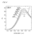
- Fig. 4 shows dielectric functions of the above plurality of silicon films.
- the vertical axis in Fig. 4 indicates the imaginary part ⁇ 2 of the dielectric function, and the horizontal axis indicates photon energy corresponding to the frequency.
- the line indicating the (imaginary part ⁇ 2 of the) dielectric function of each silicon film is given the heating temperature at which the silicon film was formed. Note that the dielectric functions in Fig.
- dielectric function represents a complex dielectric function (complex dielectric constant) with the real part and the imaginary part.
- the dielectric functions of the above silicon films differ from one another, and differences in the values of the imaginary parts ⁇ 2 are evident in the vicinity of the frequencies at the peaks of the imaginary parts ⁇ 2 . These differences are considered to depend on differences in the SiH and SiH 2 contents.
- the present embodiment focuses on differences in the peak values of the imaginary parts ⁇ 2 of a plurality of silicon films and differences in photon energy (or frequency) at the peaks of the imaginary parts ⁇ 2 .
- a silicon film that has the lowest SiH and SiH 2 contents i.e., the silicon film formed at the substrate temperature of 310°C in Table 1 is a reference silicon film serving as a reference.
- a difference between the peak value of the imaginary part ⁇ 2 of the dielectric function of the reference silicon film (hereinafter, referred to as a "reference peak value”) and the peak value of the imaginary part ⁇ 2 of the dielectric function of each of the other silicon films (hereinafter, each referred to as a “sa “sa “sample silicon film”) is regarded as one of parameters to be focused on (hereinafter, this difference is referred to as a "first shift amount").
- the value of the first shift amount of the sample silicon film formed at the heating temperature of 80°C is indicated by the length of an arrow given a reference numeral A1.
- a difference between the frequency (or photon energy) corresponding to the reference peak value of the reference silicon film and the frequency at the peak of the imaginary part ⁇ 2 of the dielectric function of each sample silicon film is also regarded as another one of the parameters to be focused on (hereinafter, this difference is referred to as a "second shift amount").
- a value equivalent to the second shift amount of the sample silicon film formed at the heating temperature of 80°C is indicated by the length of an arrow given a reference numeral B1.
- f H is the volume fraction of voids generated in a sample silicon film due to the presence of SiH
- f HH is the volume fraction of voids generated in the sample silicon film due to the presence of SiH 2
- ⁇ 310 is the dielectric function of the reference silicon film having the lowest SiH and SiH 2 contents
- ⁇ b is the dielectric function of the vacuum
- Eq. 1 may be regarded as a difference in the volume fraction of voids due to the presence of SiH between the reference silicon film and the sample silicon film (the same applies to f HH ).
- the relationship between the SiH and SiH 2 contents and the values of the first and second shift amounts (i.e., reference information 721 in Fig. 3 ) is derived using Eq. 1.
- the values of the first shift amount and the second shift amount of the silicon film are specified using Eq. 1, which makes it possible to accurately acquire the SiH and SiH 2 contents in the silicon film.
- the generation of the reference information 721 and the measurement of a silicon film on the glass substrate 9 will be described in order in more detail.
- the first shift amount of each sample silicon film is considered as a change in the dielectric constant from the dielectric function of the reference silicon film, the change being caused by the presence of voids that depends on SiH and SiH 2 (or an increase in the volume fraction of voids when compared with the case of the reference silicon film). Furthermore, since the band gap of a silicon film varies with different hydrogen contents (i.e., the photon energy changes with increasing hydrogen content), the second shift amount is considered to result directly from SiH and SiH 2 .
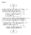
- Fig. 5 is a flowchart of the preliminary processing, i.e., the processing for generating the reference information 721.
- silicon films are first formed on a plurality of silicon substrates by CVD under different film-forming conditions (step S11).
- the heating temperatures of silicon substrates in the CVD process are set to 310°C, 280°C, 230°C, 180°C, 130°C, and 80°C, and silicon films are sequentially formed on the silicon substrates.
- the silicon films formed by CVD are amorphous. Note that the silicon films may contain microcrystalline silicon.
- the SiH and SiH 2 contents in the silicon film on each of the silicon substrates are acquired by an infrared spectrometer as shown in Table 1 discussed above, and are input to the reference information generation part 73 in Fig. 3 (step S12).
- a plurality of silicon films that are produced by changing the heating temperature of silicon substrates into multiple different temperatures in the CVD process have different SiH and SiH 2 contents.
- the silicon film formed at the substrate temperature of 310°C in Table 1 is referred to as the "reference silicon film”, and the other silicon films are referred to as the "sample silicon films”.
- the reference silicon film serving as a reference and whose SiH and SiH 2 contents are known, and the other silicon films whose SiH and SiH 2 contents are known, are prepared. Note that such a plurality of silicon films having different SiH and SiH 2 contents may be produced by changing conditions other than the heating temperature of silicon substrates.
- the spectroscopic ellipsometer 3 in Fig. 1 emitting polarized white light to a predetermined position (e.g., center) of each silicon film and receiving reflected light from the silicon film, and measured spectra are acquired by the calculation part 7.
- the dielectric function and film thickness based on a Tauc-Lorentz model are fitted within a predetermined numerical range so that the theoretical frequency spectra of the phase difference and the reflection amplitude ratio angle obtained using the Tauc-Lorentz model are closest to the measured spectra.
- the dielectric function and film thickness of each silicon film are determined (step S13).
- a model other than the Tauc-Lorentz model may be used.
- the values of the volume fractions f H and f HH of voids and the dielectric function ⁇ b of the vacuum in Eq. 1 above are determined using the dielectric function of each sample silicon film and the dielectric function ⁇ 310 of the reference silicon film (hereinafter, referred to as a "reference dielectric function ⁇ 310 ") that have been acquired in the above processing of step S13.
- the imaginary part of the dielectric function ⁇ h in the effective medium theoretical equation is expressed as the function obtained by moving the imaginary part of the reference dielectric function ⁇ 310 by the first shift amount A in the direction of the dielectric constant (vertical axis direction in Fig. 4 ) and by the second shift amount B in the direction of the frequency (horizontal axis direction in Fig. 4 ).
- the real part of the dielectric function ⁇ h is also expressed using the reference dielectric function ⁇ 310 , the first shift amount A, and the second shift amount B, based on Kramers-Kronig relations.
- the volume fractions f H and f HH of voids, the dielectric function ⁇ b of the vacuum, the first shift amount A, and the second shift amount B are fitted so that the dielectric function ⁇ h that is expressed with the first shift amount A and the second shift amount B and satisfies the effective medium theoretical equation is closest to the acquired dielectric function of the sample silicon film.
- the dielectric function expressed using the effective medium theory that includes the first shift amount A and the second shift amount B as parameters is compared with the dielectric function acquired using the Tauc-Lorentz model.
- the values of the volume fractions f H and f HH , the first shift amount A, and the second shift amount B of the sample silicon film are determined (step S 14).
- the dielectric function ⁇ b of the vacuum is the same for all the sample silicon films, and determined such that the degree of fitting increases for all the sample silicon films.
- the reference information generation part 73 functions that respectively represent the SiH and SiH 2 contents with the first shift amount A and the second shift amount B as variables are generated as the reference information 721 from the values of the first shift amounts A and the second shift amounts B of the plurality of sample silicon films and the SiH and SiH 2 contents acquired through the processing of step S12 (step S15).
- the reference information generation part 73 obtains coefficients ⁇ 1 to ⁇ 4.
- the reference information 721 is stored in the storage part 72 as preparation for the measurement of an unknown silicon film, which will be described later.
- Fig. 6 is a flowchart of the processing for acquiring the SiH and SiH 2 contents in a silicon film on the glass substrate 9.
- the spectroscopic ellipsometer 3 performs measurement on a predetermined position of the silicon film on the glass substrate 9 so as to acquire measured spectra (step S21).
- the imaginary part of the dielectric function ⁇ h in the effective medium theoretical equation is expressed as the function obtained by moving the imaginary part of the reference dielectric function ⁇ 310 by the first shift amount A in the direction of the dielectric constant (vertical axis direction in Fig. 4 ) and by the second shift amount B in the direction of the frequency (horizontal axis direction in Fig. 4 ).
- the real part of the dielectric function ⁇ h is also expressed using the first shift amount A and the second shift amount B, based on the Kramers-Kronig relations.
- fitting is performed so that the theoretical spectra obtained from these values (i.e., theoretical frequency spectra of the phase difference and the reflection amplitude ratio angle) are closest to the measured spectra.
- fitting parameters namely, the values of the volume fractions f H and f HH , the first shift amount A, the second shift amount B, and the film thickness d of the silicon film, are determined (step S22).
- the dielectric function ⁇ b in the effective medium theoretical equation has been obtained through the processing in Fig. 5 .
- the above-described fitting processing can be regarded as processing for adapting, to the dielectric function derived from the measured spectra, the dielectric function ⁇ h that is expressed by shifting the imaginary part of the reference dielectric function ⁇ 310 by the first shift amount A and the second shift amount B in the vertical axis direction and the horizontal axis direction, respectively, in Fig. 4 .
- the first shift amount A is the difference between the reference peak value (peak value of the imaginary part) of the dielectric function of the reference silicon film and the peak value of the imaginary part of the dielectric function derived from the measured spectra (i.e., dielectric function that can be derived from the measured spectra), and that the second shift amount B is the difference between the frequency corresponding to the reference peak value and the frequency at the peak of the imaginary part of the dielectric function derived from the measured spectra.
- the reference information 721 includes the functions that respectively represent the SiH and SiH 2 contents with the first shift amount A and the second shift amount B as variables.
- the values of the SiH and SiH 2 contents can be determined by substituting the values of the first shift amount A and the second shift amount B in the functions. That is, the values of the SiH and SiH 2 contents are obtained based on the values of the first shift amount A and the second shift amount B, and the reference information 721 (step S23).
- the dielectric function of the silicon film on the glass substrate 9 can also be obtained from the reference dielectric function ⁇ 310 and the values of the first shift amount A and the second shift amount B.
- the first shift amount and the second shift amount which represent the dielectric function ⁇ h in the effective medium theoretical equation, each as the function of the SiH and SiH 2 contents (i.e., the dielectric function ⁇ h in the effective medium theoretical equation is expressed using the SiH and SiH 2 contents as parameters) and to directly obtain the values of the SiH and SiH 2 contents through the fitting processing of step S22.
- the SiH and SiH 2 contents are substantially obtained based on the values of the first shift amount A and the second shift amount B. and the reference information 721.
- Table 2 shows the measurement results from the hydrogen content acquiring apparatus 1 and the measurement results from an external infrared spectrometer, the column denoted as “Spectroscopic Ellipsometry” at the top showing the measurement results from the hydrogen content acquiring apparatus 1, and the column denoted as “Infrared Spectroscopy” at the top showing the measurement results from the infrared spectrometer. Since it is difficult for the infrared spectrometer to measure a silicon film on a glass substrate, Table 2 shows the results of measurement performed on a silicon film formed by CVD (plasma CVD) on a native oxide film of a silicon substrate. The SiH and SiH 2 contents acquired by the hydrogen content acquiring apparatus 1 almost match those acquired by the infrared spectrometer.
- CVD plasma CVD
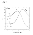
- Fig. 7 shows dielectric functions of the silicon film on the above silicon substrate.
- Solid lines given a reference numeral L1 in Fig. 7 represent the dielectric function obtained by the hydrogen content acquiring apparatus 1 using the effective medium theoretical equation
- a plurality of circles given a reference numeral L2 in Fig. 7 represent the dielectric function extracted from the measured spectra acquired by the spectroscopic ellipsometer 3 (dielectric function derived without using the effective medium theoretical equation).
- a left-side bell-shaped curve in Fig. 7 represents the real part ⁇ 1 of the dielectric function
- a right-side bell-shaped curve represents the imaginary part ⁇ 2 .
- the reference information 721 that associates the values of a group of parameters including the first shift amount and the second shift amount with the SiH and SiH 2 contents is stored. Furthermore, measured spectra are acquired by the spectroscopic ellipsometer 3 performing measurement on a silicon film on the glass substrate 9. Accordingly, the values of the group of parameters are obtained from the measured spectra, and the values of the SiH and SiH 2 contents are obtained based on the values of the group of parameters and the reference information 721. In this way, the hydrogen content acquiring apparatus 1 is capable of accurately obtaining the SiH and SiH 2 contents in a silicon film, using the spectroscopic ellipsometer 3. This enables appropriate quality control of solar cells manufactured using the glass substrate 9.
- Japanese Patent Application Laid Open Nos. 2003-302334 and 2004-93436 disclose effective medium approximation models in which it is assumed that a film to be analyzed is configured by a simple mixture of a plurality of materials.
- the present embodiment constructs an effective medium theoretical equation that takes into account voids generated due to the presence of SiH and the presence of SiH 2 in a silicon film.
- the present embodiment uses a characteristic dielectric function model that expresses the dielectric function ⁇ h in the effective medium theoretical equation using the first shift amount and the second shift amount as parameters, thereby making it possible to easily and accurately obtain the SiH and SiH 2 contents.
- the hydrogen content i.e., SiH and SiH 2 contents
- the silicon film is formed on a glass substrate, accurate measurement of the hydrogen content is difficult because of reflection of infrared radiation on the glass substrate.
- infrared spectroscopy if a multilayer film is formed on a substrate, it is difficult to measure the hydrogen content.
- the size of the infrared spectrometer is large, moving the spectrometer and performing measurement in a wide range of the substrate is difficult, and in order to perform measurement on each portion of the substrate, that portion needs to be cut out and set in the infrared spectrometer.
- the SiH and SiH 2 contents in a silicon film are acquired using the spectroscopic ellipsometer 3, accurate measurement is possible even if the silicon film is formed on a glass substrate. Furthermore, even if a multilayer film is formed on a substrate, the SiH and SiH 2 contents can be acquired by, through fitting, obtaining the values of the first shift amount and the second shift amount of a silicon film constituting one layer of the multilayer film.
- the spectroscopic ellipsometer 3 is smaller than the infrared spectrometer, moving the spectroscopic ellipsometer 3 (without cutting out a portion of the substrate) and performing measurement in a wide range of the substrate can be easily realized. In this way, no constraints such as the type and size of an object on which a silicon film is formed are imposed on the measurement of the hydrogen content by the hydrogen content acquiring apparatus 1, and even if a silicon film is part of a multilayer film, it is possible to measure the hydrogen content.
- the hydrogen content acquiring apparatus 1 is also capable of acquiring the thickness, optical constants and the like of a silicon film simultaneously with the hydrogen content therein.
- the difference between the reference peak value, which is the peak value of the imaginary part of the dielectric function of the reference silicon film, and the peak value of the imaginary part of the dielectric function of each sample silicon film is obtained as the value of the first shift amount, and the difference between the frequency corresponding to the reference peak value and the frequency at the peak of the imaginary part of the dielectric function of the sample silicon film is obtained as the value of the second shift amount (step S14).
- the values of the first shift amount and the second shift amount of each sample silicon film are obtained without using the effective medium theoretical equation. Then, as in the above-described exemplary processing, reference information that associates the values of the first shift amount and the second shift amount with the SiH and SiH 2 contents is generated (step S15).
- the spectroscopic ellipsometer 3 performs measurement on the silicon film so as to acquire measured spectra ( Fig. 6 : step S21). Then, the dielectric function (i.e., dielectric function of the silicon film on the glass substrate 9) is acquired from the measured spectra using the Tauc-Lorentz model, the difference between the reference peak value of the reference silicon film and the peak value of the imaginary part of that dielectric function is obtained as the value of the first shift amount, and the difference between the frequency corresponding to the reference peak value and the frequency at the peak of the imaginary part of that dielectric function is obtained as the value of the second shift amount (step S22).
- the dielectric function i.e., dielectric function of the silicon film on the glass substrate 9
- the difference between the reference peak value of the reference silicon film and the peak value of the imaginary part of that dielectric function is obtained as the value of the first shift amount
- the difference between the frequency corresponding to the reference peak value and the frequency at the peak of the imaginary part of that dielectric function is obtained as
- the SiH and SiH 2 contents are specified based on the values of the first shift amount and the second shift amount, and the reference information (step S23).
- the SiH and SiH 2 contents in a silicon film are obtained without using the effective medium theoretical equation.
- the hydrogen content acquiring apparatus 1 may also be configured such that reference information that associates the peak value of the imaginary part of the dielectric function of each sample silicon film and the frequency at the peak of the imaginary part with the SiH and SiH 2 contents is prepared, and when measuring the hydrogen content, the SiH and SiH 2 contents are obtained based on the peak value of the imaginary part of the dielectric function that is acquired by the spectroscopic ellipsometer 3 performing measurement on a silicon film on the glass substrate 9, on the frequency at the peak of the imaginary part, and on the reference information.
- the hydrogen content acquiring apparatus 1 is capable of acquiring the SiH and SiH 2 contents with a certain degree of accuracy.
- step S15 in Fig. 5 if R H is a difference in the SiH content between the reference silicon film and each sample silicon film and R HH is a difference in the SiH 2 content therebetween, functions that respectively represent R H and R HH with the first shift amount A and the second shift amount B as variables may be acquired as the reference information.
- step S23 in Fig. 6 the values of R H and R HH are obtained from the values of the first shift amount A and the second shift amount B of the silicon film on the glass substrate 9, and the SiH and SiH 2 contents in the reference silicon film are added respectively to the values of R H and R HH .
- the SiH and SiH 2 contents in the silicon film on the glass substrate 9 are calculated.
- these functions respectively represent the SiH and SiH 2 contents, using the first shift amount A and the second shift amount B as variables.
- step S12 in Fig. 5 the SiH and SiH 2 contents in a silicon film may be acquired by a technique other than infrared spectroscopy.
- the hydrogen content acquiring apparatus 1 is capable of acquiring the SiH and SiH 2 contents in a silicon film formed on various types of objects such as substrates for solar cells other than the glass substrate 9, and plastic films, and the like. Furthermore, a silicon film may be formed by a method other than CVD.
Landscapes
- Physics & Mathematics (AREA)
- General Physics & Mathematics (AREA)
- Health & Medical Sciences (AREA)
- Life Sciences & Earth Sciences (AREA)
- Chemical & Material Sciences (AREA)
- Analytical Chemistry (AREA)
- Biochemistry (AREA)
- General Health & Medical Sciences (AREA)
- Immunology (AREA)
- Pathology (AREA)
- Mathematical Physics (AREA)
- Investigating Or Analysing Materials By Optical Means (AREA)
Abstract
Description
- The present invention relates to a technique for acquiring SiH and SiH2 contents in a silicon film formed on an object.
- With increasing attention to global environmental issues in recent years, solar cells that utilize clean sunlight have been developed, and in particular, thin film silicon solar cells that allow increases in surface area and reductions in cost are gathering attention as next-generation solar cells. In the manufacture of thin film silicon solar cells, an amorphous silicon film (hereinafter, simply referred to as a "silicon film") is formed on a glass substrate by chemical vapor deposition (CVD) or the like.
- Japanese Patent Application Laid Open Nos.
2003-302334 2004-93436 - Incidentally, it is known that a silicon film formed by CVD contains SiH and SiH2 and that SiH2 can cause photo-deterioration. The SiH2 content in silicon films thus has a significant influence on the conversion efficiency of thin film silicon solar cells. For this reason, it is very important to measure the hydrogen content (in particular, the SiH2 content) in silicon films, in terms of quality control of thin film silicon solar cells.
- With an infrared spectrometer, the SiH and SiH2 contents can be measured by acquiring an infrared absorption spectrum of a silicon film formed on a silicon substrate and detecting peaks appearing due to SiH bonding and SiH2 bonding from the spectrum. However, when a silicon film is formed on a glass substrate, accurate measurement of the SiH and SiH2 contents is difficult due to reflection of infrared radiation on the glass substrate. Accordingly, there is demand for a new technique that enables accurate acquisition of the SiH and SiH2 contents even in a silicon film formed on a glass substrate.
- The present invention is directed to a hydrogen content acquiring apparatus for acquiring SiH and SiH2 contents in a silicon film formed on an object, and it is an object of the present invention is to provide a new technique that enables accurate acquisition of SiH and SiH2 contents in a silicon film.
- The hydrogen content acquiring apparatus according to the present invention is a hydrogen content acquiring apparatus for acquiring SiH and SiH2 contents in a silicon film formed on an object. It includes a spectroscopic ellipsometer, a storage part that stores reference information that associates values of a predetermined group of parameters with SiH and SiH2 contents, and a content calculation part that obtains values of the group of parameters from measured spectra acquired by the spectroscopic ellipsometer performing measurement on a silicon film on an object, and obtains SiH and SiH2 contents based on the values of the group of parameters and the reference information.
- According to the present invention, SiH and SiH2 contents in a silicon film can be accurately obtained using the spectroscopic ellipsometer.
- In a preferable embodiment of the present invention, one of the group of parameters is a first shift amount that is a difference between a reference peak value that is a peak value of an imaginary part of a dielectric function of a silicon film serving as a reference, and a peak value of an imaginary part of a dielectric function derived from the measured spectra, another one of the group of parameters is a second shift amount that is a difference between a frequency corresponding to the reference peak value and a frequency at the peak of the imaginary part of the dielectric function derived from the measured spectra, and the reference information includes functions that respectively represent SiH and SiH2 contents with the first shift amount and the second shift amount as variables.
- In this case, it is preferable that the content calculation part obtains values of the first shift amount and the second shift amount of the silicon film on the object, using an effective medium theory that includes a volume fraction of voids generated in the silicon film due to the presence of SiH and a volume fraction of voids generated in the silicon film due to the presence of SiH2, as parameters. As a result, it is possible to more accurately acquire SiH and SiH2 contents in a silicon film.
- In another preferable embodiment of the present invention, the values of the group of parameters include a peak value of an imaginary part of a dielectric function derived from the measured spectra, and a frequency at the peak of the imaginary part.
- According to one aspect of the present invention, the object is a substrate for solar cells. In this case, appropriate solar-cell quality control is possible.
- The present invention is also directed to a hydrogen content acquiring method for acquiring SiH and SiH2 contents in a silicon film formed on an object.
- These and other objects, features, aspects and advantages of the present invention will become more apparent from the following detailed description of the present invention when taken in conjunction with the accompanying drawings.
-
-
Fig. 1 is a perspective view showing a hydrogen content acquiring apparatus; -
Fig. 2 shows a configuration of a computer; -
Fig. 3 is a block diagram showing a functional configuration implemented by a computer; -
Fig. 4 shows dielectric functions of a plurality of silicon films; -
Fig. 5 is a flowchart of processing for generating reference information; -
Fig. 6 is a flowchart of processing for acquiring the hydrogen content in a silicon film; and -
Fig. 7 shows dielectric functions of a silicon film. -
Fig. 1 is a perspective view showing a hydrogencontent acquiring apparatus 1 according to an embodiment of the present invention. The hydrogencontent acquiring apparatus 1 is configured to acquire SiH and SiH2 contents (hereinafter, also referred to collectively as the "hydrogen content") contained in an amorphous silicon film (hereinafter, simply referred to as a "silicon film") formed on aglass substrate 9 for thin film silicon solar cells. Theglass substrate 9 measures, for example, 1 to 2 meters (m) per side. - The hydrogen
content acquiring apparatus 1 includes animaging part 2 that images a surface of theglass substrate 9, aspectroscopic ellipsometer 3 for acquiring measured spectra described later, a Y-direction moving part 4 capable of moving in the Y direction inFig. 1 , anX-direction moving part 5 capable of moving in the X direction inFig. 1 , and acomputer 6 configured by, for example, a CPU that performs various types of computational processing and a memory that stores various types of information. Thecomputer 6 functions as a controller that controls the constituent elements of the hydrogencontent acquiring apparatus 1. TheX-direction moving part 5 is provided on the Y-direction moving part 4, and theimaging part 2 and thespectroscopic ellipsometer 3 are fixed to theX-direction moving part 5. In the hydrogencontent acquiring apparatus 1, a position that is irradiated with light by thespectroscopic ellipsometer 3 can be disposed at any position on theglass substrate 9 as intended. - The
spectroscopic ellipsometer 3 includes anillumination part 31 and alight receiving part 32 that are disposed above the glass substrate 9 (on the (+Z) side inFig. 1 ), theillumination part 31 emitting polarized white light toward theglass substrate 9, and thelight receiving part 32 receiving reflected light from theglass substrate 9. Thelight receiving part 32 includes an analyzer that receives reflected light and a spectroscope that acquires the spectral intensity of reflected light, and the rotational position of the analyzer and the spectral intensity of reflected light acquired by the spectroscope are output to thecomputer 6. In thecomputer 6, a phase difference and reflection amplitude ratio angle between p- and s-polarized light components are obtained as a polarized state of each of light rays having a plurality of frequencies (or wavelengths). That is, frequency spectra of the phase difference and the reflection amplitude ratio angle (hereinafter, referred to collectively as "measured spectra") are acquired. -
Fig. 2 shows a configuration of thecomputer 6. Thecomputer 6 is configured as a general computer system in which aCPU 61 that performs various types of computational processing, aROM 62 that stores base programs, and aRAM 63 that stores various types of information are connected to a bus line. Afixed disk 65 for information storage, adisplay 66 that displays various types of information, a keyboard 67a and amouse 67b that receive input from an operator, a reading/writing apparatus 68 that reads or writes information from or to a computer-readable recording medium 81 such as an optical disk, a magnetic disk, or a magneto-optical disk, and acommunication part 69 that performs communication with external devices are further connected to the bus line appropriately via an interface (I/F) or the like. - In the
computer 6, aprogram 810 is read from therecording medium 81 via the reading/writing apparatus 68 and stored in thefixed disk 65 in advance. Then, thecomputer 6 performs processing, serving as a computation part described later, by theprogram 810 being copied into theRAM 63 and theCPU 61 executing computational processing in accordance with the program in the RAM 63 (i.e., by the computer executing the program). -
Fig. 3 is a block diagram showing a functional configuration implemented by, for example, theCPU 61, theROM 62, theRAM 63, and thefixed disk 65 as a result of theCPU 61 operating in accordance with theprogram 810. In acalculation part 7 inFig. 3 , acontent calculation part 71 and a referenceinformation generation part 73 are functions implemented by theCPU 61 and the like, and thestorage part 72 is a function implemented by thefixed disk 65 and the like. Note that the functions of thecalculation part 7 may be implemented by a dedicated electrical circuit, or an electrical circuit may be used in part. - Next, the principle of measurement of the hydrogen content performed in the hydrogen
content acquiring apparatus 1 will be described. It is assumed here that a plurality of silicon films that differ from one another in at least one of the SiH and SiH2 contents have been prepared by setting the heating temperature of silicon substrates in the CVD process to 310°C, 280°C, 230°C, 180°C, 130°C, and 80°C and sequentially forming silicon films on the silicon substrates. Table 1 shows the SiH and SiH2 contents in the silicon films on the silicon substrates, the column denoted as "substrate Temperature" at the top showing the heating temperature of the silicon substrates when forming the silicon films. -
[Table 1] Substrate Temperature SiH Content (at.%) SiH2 Content (at.%) 310°C 5.3 1.1 280°C 6.9 1.1 230°C 7.9 3.6 180°C 9.0 6.1 130°C 9.0 8.5 80°C 9.0 13.6 - As shown in Table 1, the silicon film formed at the lowest heating temperature (substrate temperature of 80°C) has the highest SiH and SiH2 contents (in atomic percents in Table 1), and the silicon film formed at the highest heating temperature (substrate temperature of 310°C) has the lowest SiH and SiH2 contents.
-
Fig. 4 shows dielectric functions of the above plurality of silicon films. Dielectric function ε is expressed as a complex function with a real part ε1 and an imaginary part ε2 (i.e., (ε = ε1 + iε2) where i is the imaginary unit). The vertical axis inFig. 4 indicates the imaginary part ε2 of the dielectric function, and the horizontal axis indicates photon energy corresponding to the frequency. InFig. 4 , the line indicating the (imaginary part ε2 of the) dielectric function of each silicon film is given the heating temperature at which the silicon film was formed. Note that the dielectric functions inFig. 4 are extracted from the measured spectra acquired by thespectroscopic ellipsometer 3, i.e., they are obtained without using a Tauc-Lorentz model described later. Hereinafter, a simply called "dielectric function" represents a complex dielectric function (complex dielectric constant) with the real part and the imaginary part. - As shown in
Fig. 4 , the dielectric functions of the above silicon films differ from one another, and differences in the values of the imaginary parts ε2 are evident in the vicinity of the frequencies at the peaks of the imaginary parts ε2. These differences are considered to depend on differences in the SiH and SiH2 contents. Thus, the present embodiment focuses on differences in the peak values of the imaginary parts ε2 of a plurality of silicon films and differences in photon energy (or frequency) at the peaks of the imaginary parts ε2. - Specifically, it is assumed, in the measurement of the hydrogen content by the hydrogen
content acquiring apparatus 1, that a silicon film that has the lowest SiH and SiH2 contents, i.e., the silicon film formed at the substrate temperature of 310°C in Table 1 is a reference silicon film serving as a reference. Then, a difference between the peak value of the imaginary part ε2 of the dielectric function of the reference silicon film (hereinafter, referred to as a "reference peak value") and the peak value of the imaginary part ε2 of the dielectric function of each of the other silicon films (hereinafter, each referred to as a "sample silicon film") is regarded as one of parameters to be focused on (hereinafter, this difference is referred to as a "first shift amount"). InFig. 4 , the value of the first shift amount of the sample silicon film formed at the heating temperature of 80°C is indicated by the length of an arrow given a reference numeral A1. A difference between the frequency (or photon energy) corresponding to the reference peak value of the reference silicon film and the frequency at the peak of the imaginary part ε2 of the dielectric function of each sample silicon film is also regarded as another one of the parameters to be focused on (hereinafter, this difference is referred to as a "second shift amount"). InFig. 4 , a value equivalent to the second shift amount of the sample silicon film formed at the heating temperature of 80°C is indicated by the length of an arrow given a reference numeral B1. - Meanwhile, when SiH and SiH2 are contained in a silicon film, voids will be generated in the silicon film due to the presence of each of SiH and SiH2 (i.e., resulting from each of SiH and SiH2). Accordingly, if fH is the volume fraction of voids generated in a sample silicon film due to the presence of SiH, fHH is the volume fraction of voids generated in the sample silicon film due to the presence of SiH2, ε310 is the dielectric function of the reference silicon film having the lowest SiH and SiH2 contents, and εb is the dielectric function of the vacuum, the dielectric function εh of the sample silicon film with voids is considered to satisfy Eq. 1 according to effective medium approximation.
-

- Note that although it is also possible in Eq. 1 to take into account the volume fraction and dielectric function of SiH and the volume fraction and dielectric function of SiH2, these parameters have been omitted in Eq. 1 in order to simplify the computation. In Eq. 1, fH may be regarded as a difference in the volume fraction of voids due to the presence of SiH between the reference silicon film and the sample silicon film (the same applies to fHH).
- In the hydrogen
content acquiring apparatus 1, as preliminary processing, the relationship between the SiH and SiH2 contents and the values of the first and second shift amounts (i.e.,reference information 721 inFig. 3 ) is derived using Eq. 1. Then, when measuring a silicon film on theglass substrate 9, the values of the first shift amount and the second shift amount of the silicon film are specified using Eq. 1, which makes it possible to accurately acquire the SiH and SiH2 contents in the silicon film. Hereinafter, the generation of thereference information 721 and the measurement of a silicon film on theglass substrate 9 will be described in order in more detail. - Note that the first shift amount of each sample silicon film is considered as a change in the dielectric constant from the dielectric function of the reference silicon film, the change being caused by the presence of voids that depends on SiH and SiH2 (or an increase in the volume fraction of voids when compared with the case of the reference silicon film). Furthermore, since the band gap of a silicon film varies with different hydrogen contents (i.e., the photon energy changes with increasing hydrogen content), the second shift amount is considered to result directly from SiH and SiH2.
-
Fig. 5 is a flowchart of the preliminary processing, i.e., the processing for generating thereference information 721. When generating thereference information 721, silicon films are first formed on a plurality of silicon substrates by CVD under different film-forming conditions (step S11). In the present embodiment, as described above, the heating temperatures of silicon substrates in the CVD process are set to 310°C, 280°C, 230°C, 180°C, 130°C, and 80°C, and silicon films are sequentially formed on the silicon substrates. The silicon films formed by CVD are amorphous. Note that the silicon films may contain microcrystalline silicon. - Then, the SiH and SiH2 contents in the silicon film on each of the silicon substrates are acquired by an infrared spectrometer as shown in Table 1 discussed above, and are input to the reference
information generation part 73 inFig. 3 (step S12). A plurality of silicon films that are produced by changing the heating temperature of silicon substrates into multiple different temperatures in the CVD process have different SiH and SiH2 contents. In the present processing as well, the silicon film formed at the substrate temperature of 310°C in Table 1 is referred to as the "reference silicon film", and the other silicon films are referred to as the "sample silicon films". Through the above-described processing of steps S11 and S12, the reference silicon film serving as a reference and whose SiH and SiH2 contents are known, and the other silicon films whose SiH and SiH2 contents are known, are prepared. Note that such a plurality of silicon films having different SiH and SiH2 contents may be produced by changing conditions other than the heating temperature of silicon substrates. - When the plurality of silicon films have been prepared, measurement is performed by the
spectroscopic ellipsometer 3 inFig. 1 emitting polarized white light to a predetermined position (e.g., center) of each silicon film and receiving reflected light from the silicon film, and measured spectra are acquired by thecalculation part 7. In the present embodiment, the dielectric function and film thickness based on a Tauc-Lorentz model are fitted within a predetermined numerical range so that the theoretical frequency spectra of the phase difference and the reflection amplitude ratio angle obtained using the Tauc-Lorentz model are closest to the measured spectra. As a result, the dielectric function and film thickness of each silicon film are determined (step S13). Of course, a model other than the Tauc-Lorentz model may be used. - Then, in the reference
information generation part 73, the values of the volume fractions fH and fHH of voids and the dielectric function εb of the vacuum in Eq. 1 above (hereinafter, referred to as an "effective medium theoretical equation") are determined using the dielectric function of each sample silicon film and the dielectric function ε310 of the reference silicon film (hereinafter, referred to as a "reference dielectric function ε310") that have been acquired in the above processing of step S13. At this time, the imaginary part of the dielectric function εh in the effective medium theoretical equation is expressed as the function obtained by moving the imaginary part of the reference dielectric function ε310 by the first shift amount A in the direction of the dielectric constant (vertical axis direction inFig. 4 ) and by the second shift amount B in the direction of the frequency (horizontal axis direction inFig. 4 ). The real part of the dielectric function εh is also expressed using the reference dielectric function ε310, the first shift amount A, and the second shift amount B, based on Kramers-Kronig relations. Then, the volume fractions fH and fHH of voids, the dielectric function εb of the vacuum, the first shift amount A, and the second shift amount B are fitted so that the dielectric function εh that is expressed with the first shift amount A and the second shift amount B and satisfies the effective medium theoretical equation is closest to the acquired dielectric function of the sample silicon film. - In this way, for each of the plurality of sample silicon films, the dielectric function expressed using the effective medium theory (in the present embodiment, effective medium approximation) that includes the first shift amount A and the second shift amount B as parameters is compared with the dielectric function acquired using the Tauc-Lorentz model. As a result, the values of the volume fractions fH and fHH, the first shift amount A, and the second shift amount B of the sample silicon film are determined (step S 14). Note that the dielectric function εb of the vacuum is the same for all the sample silicon films, and determined such that the degree of fitting increases for all the sample silicon films.
- In the reference
information generation part 73, functions that respectively represent the SiH and SiH2 contents with the first shift amount A and the second shift amount B as variables are generated as thereference information 721 from the values of the first shift amounts A and the second shift amounts B of the plurality of sample silicon films and the SiH and SiH2 contents acquired through the processing of step S12 (step S15). For example, when the SiH content is expressed as (α1·A + α2·B) and the SiH2 content is expressed as (α3·A + α4·B), the referenceinformation generation part 73 obtains coefficients α1 to α4. Thereference information 721 is stored in thestorage part 72 as preparation for the measurement of an unknown silicon film, which will be described later. In the preliminary processing, there may be also additionally acquired the relationship between the SiH content and the volume fraction fH and the relationship between the SiH2 content and the volume fraction fHH, and these relationships may be included in thereference information 721. -
Fig. 6 is a flowchart of the processing for acquiring the SiH and SiH2 contents in a silicon film on theglass substrate 9. When theglass substrate 9 whose SiH and SiH2 contents are unknown is conveyed into the hydrogencontent acquiring apparatus 1, thespectroscopic ellipsometer 3 performs measurement on a predetermined position of the silicon film on theglass substrate 9 so as to acquire measured spectra (step S21). - In the
content calculation part 71 inFig. 3 , the imaginary part of the dielectric function εh in the effective medium theoretical equation is expressed as the function obtained by moving the imaginary part of the reference dielectric function ε310 by the first shift amount A in the direction of the dielectric constant (vertical axis direction inFig. 4 ) and by the second shift amount B in the direction of the frequency (horizontal axis direction inFig. 4 ). The real part of the dielectric function εh is also expressed using the first shift amount A and the second shift amount B, based on the Kramers-Kronig relations. Then, while changing the values of the first shift amount A and the second shift amount B that represent the dielectric function εh in the effective medium theoretical equation, the values of the volume fractions fH and fHH in the effective medium theoretical equation, and the value of a film thickness d of the silicon film into multiple different values, fitting is performed so that the theoretical spectra obtained from these values (i.e., theoretical frequency spectra of the phase difference and the reflection amplitude ratio angle) are closest to the measured spectra. As a result, fitting parameters, namely, the values of the volume fractions fH and fHH, the first shift amount A, the second shift amount B, and the film thickness d of the silicon film, are determined (step S22). As discussed above, the dielectric function εb in the effective medium theoretical equation has been obtained through the processing inFig. 5 . - The above-described fitting processing can be regarded as processing for adapting, to the dielectric function derived from the measured spectra, the dielectric function εh that is expressed by shifting the imaginary part of the reference dielectric function ε310 by the first shift amount A and the second shift amount B in the vertical axis direction and the horizontal axis direction, respectively, in
Fig. 4 . Thus, it can be said that the first shift amount A is the difference between the reference peak value (peak value of the imaginary part) of the dielectric function of the reference silicon film and the peak value of the imaginary part of the dielectric function derived from the measured spectra (i.e., dielectric function that can be derived from the measured spectra), and that the second shift amount B is the difference between the frequency corresponding to the reference peak value and the frequency at the peak of the imaginary part of the dielectric function derived from the measured spectra. - As discussed above, the
reference information 721 includes the functions that respectively represent the SiH and SiH2 contents with the first shift amount A and the second shift amount B as variables. Thus, the values of the SiH and SiH2 contents can be determined by substituting the values of the first shift amount A and the second shift amount B in the functions. That is, the values of the SiH and SiH2 contents are obtained based on the values of the first shift amount A and the second shift amount B, and the reference information 721 (step S23). Furthermore, the dielectric function of the silicon film on theglass substrate 9 can also be obtained from the reference dielectric function ε310 and the values of the first shift amount A and the second shift amount B. - Note that it is also possible to express the first shift amount and the second shift amount, which represent the dielectric function εh in the effective medium theoretical equation, each as the function of the SiH and SiH2 contents (i.e., the dielectric function εh in the effective medium theoretical equation is expressed using the SiH and SiH2 contents as parameters) and to directly obtain the values of the SiH and SiH2 contents through the fitting processing of step S22. In this case as well, it can be considered that the SiH and SiH2 contents are substantially obtained based on the values of the first shift amount A and the second shift amount B. and the
reference information 721. - Table 2 shows the measurement results from the hydrogen
content acquiring apparatus 1 and the measurement results from an external infrared spectrometer, the column denoted as "Spectroscopic Ellipsometry" at the top showing the measurement results from the hydrogencontent acquiring apparatus 1, and the column denoted as "Infrared Spectroscopy" at the top showing the measurement results from the infrared spectrometer. Since it is difficult for the infrared spectrometer to measure a silicon film on a glass substrate, Table 2 shows the results of measurement performed on a silicon film formed by CVD (plasma CVD) on a native oxide film of a silicon substrate. The SiH and SiH2 contents acquired by the hydrogencontent acquiring apparatus 1 almost match those acquired by the infrared spectrometer. -
[Table 2] Spectroscopic Ellipsometry Infrared Spectroscopy SiH Content (at.%) 8.9 8.8 SiH2 Content (at.%) 8.1 8.1 -
Fig. 7 shows dielectric functions of the silicon film on the above silicon substrate. Solid lines given a reference numeral L1 inFig. 7 represent the dielectric function obtained by the hydrogencontent acquiring apparatus 1 using the effective medium theoretical equation, and a plurality of circles given a reference numeral L2 inFig. 7 represent the dielectric function extracted from the measured spectra acquired by the spectroscopic ellipsometer 3 (dielectric function derived without using the effective medium theoretical equation). A left-side bell-shaped curve inFig. 7 represents the real part ε1 of the dielectric function, and a right-side bell-shaped curve represents the imaginary part ε2. It can be seen fromFig. 7 that the dielectric function obtained by the hydrogencontent acquiring apparatus 1 using the effective medium theoretical equation closely matches the dielectric function extracted from the measured spectra, and therefore, the dielectric function can be appropriately obtained. - As described above, in the hydrogen
content acquiring apparatus 1, thereference information 721 that associates the values of a group of parameters including the first shift amount and the second shift amount with the SiH and SiH2 contents is stored. Furthermore, measured spectra are acquired by thespectroscopic ellipsometer 3 performing measurement on a silicon film on theglass substrate 9. Accordingly, the values of the group of parameters are obtained from the measured spectra, and the values of the SiH and SiH2 contents are obtained based on the values of the group of parameters and thereference information 721. In this way, the hydrogencontent acquiring apparatus 1 is capable of accurately obtaining the SiH and SiH2 contents in a silicon film, using thespectroscopic ellipsometer 3. This enables appropriate quality control of solar cells manufactured using theglass substrate 9. - Incidentally, Japanese Patent Application Laid Open Nos.
2003-302334 2004-93436 Documents - Here, consider the case in which the hydrogen content (i.e., SiH and SiH2 contents) in a silicon film is measured using an infrared spectrometer. If the silicon film is formed on a glass substrate, accurate measurement of the hydrogen content is difficult because of reflection of infrared radiation on the glass substrate. Furthermore, with infrared spectroscopy, if a multilayer film is formed on a substrate, it is difficult to measure the hydrogen content. Moreover, since the size of the infrared spectrometer is large, moving the spectrometer and performing measurement in a wide range of the substrate is difficult, and in order to perform measurement on each portion of the substrate, that portion needs to be cut out and set in the infrared spectrometer.
- In contrast, in the hydrogen
content acquiring apparatus 1 inFig. 1 , since the SiH and SiH2 contents in a silicon film are acquired using thespectroscopic ellipsometer 3, accurate measurement is possible even if the silicon film is formed on a glass substrate. Furthermore, even if a multilayer film is formed on a substrate, the SiH and SiH2 contents can be acquired by, through fitting, obtaining the values of the first shift amount and the second shift amount of a silicon film constituting one layer of the multilayer film. Moreover, since thespectroscopic ellipsometer 3 is smaller than the infrared spectrometer, moving the spectroscopic ellipsometer 3 (without cutting out a portion of the substrate) and performing measurement in a wide range of the substrate can be easily realized. In this way, no constraints such as the type and size of an object on which a silicon film is formed are imposed on the measurement of the hydrogen content by the hydrogencontent acquiring apparatus 1, and even if a silicon film is part of a multilayer film, it is possible to measure the hydrogen content. In addition, the hydrogencontent acquiring apparatus 1 is also capable of acquiring the thickness, optical constants and the like of a silicon film simultaneously with the hydrogen content therein. - Next, another exemplary processing performed by the hydrogen
content acquiring apparatus 1 will be described. In the preliminary processing according to the present exemplary processing, when the dielectric functions of the reference silicon film and a plurality of other sample silicon films have been acquired using the Tauc-Lorentz model in step S13 inFig. 5 , the difference between the reference peak value, which is the peak value of the imaginary part of the dielectric function of the reference silicon film, and the peak value of the imaginary part of the dielectric function of each sample silicon film is obtained as the value of the first shift amount, and the difference between the frequency corresponding to the reference peak value and the frequency at the peak of the imaginary part of the dielectric function of the sample silicon film is obtained as the value of the second shift amount (step S14). In other words, the values of the first shift amount and the second shift amount of each sample silicon film are obtained without using the effective medium theoretical equation. Then, as in the above-described exemplary processing, reference information that associates the values of the first shift amount and the second shift amount with the SiH and SiH2 contents is generated (step S15). - Next, when measuring a silicon film on the
glass substrate 9, thespectroscopic ellipsometer 3 performs measurement on the silicon film so as to acquire measured spectra (Fig. 6 : step S21). Then, the dielectric function (i.e., dielectric function of the silicon film on the glass substrate 9) is acquired from the measured spectra using the Tauc-Lorentz model, the difference between the reference peak value of the reference silicon film and the peak value of the imaginary part of that dielectric function is obtained as the value of the first shift amount, and the difference between the frequency corresponding to the reference peak value and the frequency at the peak of the imaginary part of that dielectric function is obtained as the value of the second shift amount (step S22). Then, the SiH and SiH2 contents are specified based on the values of the first shift amount and the second shift amount, and the reference information (step S23). In this way, in the present exemplary processing, the SiH and SiH2 contents in a silicon film are obtained without using the effective medium theoretical equation. - The hydrogen
content acquiring apparatus 1 may also be configured such that reference information that associates the peak value of the imaginary part of the dielectric function of each sample silicon film and the frequency at the peak of the imaginary part with the SiH and SiH2 contents is prepared, and when measuring the hydrogen content, the SiH and SiH2 contents are obtained based on the peak value of the imaginary part of the dielectric function that is acquired by thespectroscopic ellipsometer 3 performing measurement on a silicon film on theglass substrate 9, on the frequency at the peak of the imaginary part, and on the reference information. In this way, even if the values of the group of parameters obtained when acquiring the hydrogen content include the peak value of the imaginary part of the dielectric function derived from the measured spectra and the frequency at the peak of the imaginary part, the hydrogencontent acquiring apparatus 1 is capable of acquiring the SiH and SiH2 contents with a certain degree of accuracy. However, in order to more accurately acquire the SiH and SiH2 contents in a silicon film, it is preferable to obtain the values of the first shift amount and the second shift amount of a silicon film while using the effective medium theoretical equation as in the above-described exemplary processing. - While the above has been a description of embodiments of the present invention, the present invention is not intended to be limited to the above-described embodiments and can be modified in various ways.
- In step S15 in
Fig. 5 , if RH is a difference in the SiH content between the reference silicon film and each sample silicon film and RHH is a difference in the SiH2 content therebetween, functions that respectively represent RH and RHH with the first shift amount A and the second shift amount B as variables may be acquired as the reference information. In this case, in step S23 inFig. 6 , the values of RH and RHH are obtained from the values of the first shift amount A and the second shift amount B of the silicon film on theglass substrate 9, and the SiH and SiH2 contents in the reference silicon film are added respectively to the values of RH and RHH. As a result, the SiH and SiH2 contents in the silicon film on theglass substrate 9 are calculated. Substantially, it can also be said that these functions respectively represent the SiH and SiH2 contents, using the first shift amount A and the second shift amount B as variables. - In step S12 in
Fig. 5 , the SiH and SiH2 contents in a silicon film may be acquired by a technique other than infrared spectroscopy. - The hydrogen
content acquiring apparatus 1 is capable of acquiring the SiH and SiH2 contents in a silicon film formed on various types of objects such as substrates for solar cells other than theglass substrate 9, and plastic films, and the like. Furthermore, a silicon film may be formed by a method other than CVD. - The configurations of the above-described preferred embodiments and variations may be appropriately combined as long as there are no mutual inconsistencies.
- While the invention has been shown and described in detail, the foregoing description is in all aspects illustrative and not restrictive. It is therefore understood that numerous modifications and variations can be devised without departing from the scope of the invention.
-
- 1
- Hydrogen content acquiring apparatus
- 3
- Spectroscopic ellipsometer
- 9
- Glass substrate
- 71
- Content calculation part
- 72
- Storage part
- 721
- Reference information
- S11 to S15, S21 to S23
- Step
Claims (11)
- A hydrogen content acquiring apparatus (1) for acquiring SiH and SiH2 contents in a silicon film formed on an object (9), comprising:a spectroscopic ellipsometer (3);a storage part (72) that stores reference information (721) that associates values of a predetermined group of parameters with SiH and SiH2 contents; anda content calculation part (71) that obtains values of said group of parameters from measured spectra acquired by said spectroscopic ellipsometer performing measurement on a silicon film on an object, and obtains SiH and SiH2 contents based on the values of said group of parameters and said reference information.
- The hydrogen content acquiring apparatus according to claim 1, wherein
one of said group of parameters is a first shift amount that is a difference between a reference peak value that is a peak value of an imaginary part of a dielectric function of a silicon film serving as a reference, and a peak value of an imaginary part of a dielectric function derived from said measured spectra,
another one of said group of parameters is a second shift amount that is a difference between a frequency corresponding to said reference peak value and a frequency at the peak of the imaginary part of the dielectric function derived from said measured spectra, and
said reference information includes functions that respectively represent SiH and SiH2 contents with said first shift amount and said second shift amount as variables. - The hydrogen content acquiring apparatus according to claim 2, wherein
said content calculation part obtains values of said first shift amount and said second shift amount of the silicon film on said object, using an effective medium theory that includes a volume fraction of voids generated in the silicon film due to the presence of SiH and a volume fraction of voids generated in the silicon film due to the presence of SiH2, as parameters. - The hydrogen content acquiring apparatus according to claim 1, wherein
the values of said group of parameters include a peak value of an imaginary part of a dielectric function derived from said measured spectra, and a frequency at the peak of the imaginary part. - The hydrogen content acquiring apparatus according to any one of claims 1 to 4, wherein
said object is a substrate for solar cells. - A hydrogen content acquiring method for acquiring SiH and SiH2 contents in a silicon film formed on an object (9), comprising the steps of:a) (S11 to S15) preparing reference information (721) that associates values of a predetermined group of parameters with SiH and SiH2 contents;b) (S21, S22) acquiring measured spectra by a spectroscopic ellipsometer (3) performing measurement on a silicon film on an object, and obtaining values of said group of parameters from said measured spectra; andc) (S23) obtaining SiH and SiH2 contents based on said values of said group of parameters and said reference information.
- The hydrogen content acquiring method according to claim 6, wherein
one of said group of parameters is a first shift amount that is a difference between a reference peak value that is a peak value of an imaginary part of a dielectric function of a silicon film serving as a reference, and a peak value of an imaginary part of a dielectric function derived from said measured spectra,
another one of said group of parameters is a second shift amount that is a difference between a frequency corresponding to said reference peak value and a frequency at the peak of the imaginary part of the dielectric function derived from said measured spectra, and
said reference information includes functions that respectively represent SiH and SiH2 contents with said first shift amount and said second shift amount as variables. - The hydrogen content acquiring method according to claim 7, wherein
in said step b), values of said first shift amount and said second shift amount of the silicon film on said object are obtained using an effective medium theory that includes a volume fraction of voids generated in the silicon film due to the presence of SiH and a volume fraction of voids generated in the silicon film due to the presence of SiH2, as parameters. - The hydrogen content acquiring method according to claim 8, wherein
said step a) includes the steps of:a1) (S11, S12) preparing a reference silicon film serving as said reference and whose SiH and SiH2 contents are known, and a plurality of other sample silicon films whose SiH and SiH2 contents are known;a2) (S13) for each of said reference silicon film and said plurality of sample silicon films, performing measurement using said spectroscopic ellipsometer so as to acquire a dielectric function;a3) (S14) for each of said plurality of sample silicon films, comparing a dielectric function expressed using said effective medium theory that includes said first shift amount and said second shift amount as parameters with the dielectric function acquired in said step a2), so as to determine values of said first shift amounts and said second shift amounts of said plurality of sample silicon films; anda4) (S15) generating said functions that respectively represent SiH and SiH2 contents with said first shift amount and said second shift amount as variables, from the values of said first shift amounts and said second shift amounts of said plurality of sample silicon films. - The hydrogen content acquiring method according to claim 6, wherein
the values of said group of parameters include a peak value of an imaginary part of a dielectric function derived from said measured spectra, and a frequency at the peak of the imaginary part. - The hydrogen content acquiring method according to any one of claims 6 to 10, wherein
said object is a substrate for solar cells.
Applications Claiming Priority (2)
| Application Number | Priority Date | Filing Date | Title |
|---|---|---|---|
| JP2010040035A JP5397693B2 (en) | 2010-02-25 | 2010-02-25 | Hydrogen content acquisition apparatus and hydrogen content acquisition method |
| PCT/JP2011/053137 WO2011105252A1 (en) | 2010-02-25 | 2011-02-15 | Hydrogen content ratio acquiring apparatus and hydrogen content ratio acquiring method |
Publications (2)
| Publication Number | Publication Date |
|---|---|
| EP2541231A1 true EP2541231A1 (en) | 2013-01-02 |
| EP2541231A4 EP2541231A4 (en) | 2015-09-23 |
Family
ID=44506666
Family Applications (1)
| Application Number | Title | Priority Date | Filing Date |
|---|---|---|---|
| EP11747216.7A Withdrawn EP2541231A4 (en) | 2010-02-25 | 2011-02-15 | APPARATUS AND METHOD FOR ACQUIRING HYDROGEN CONTENT |
Country Status (4)
| Country | Link |
|---|---|
| EP (1) | EP2541231A4 (en) |
| JP (1) | JP5397693B2 (en) |
| TW (1) | TWI431265B (en) |
| WO (1) | WO2011105252A1 (en) |
Families Citing this family (1)
| Publication number | Priority date | Publication date | Assignee | Title |
|---|---|---|---|---|
| WO2012117601A1 (en) * | 2011-03-01 | 2012-09-07 | 大日本スクリーン製造株式会社 | Carbon-content-percentage acquisition device and carbon-content-percentage acquisition method |
Family Cites Families (8)
| Publication number | Priority date | Publication date | Assignee | Title |
|---|---|---|---|---|
| JP3816440B2 (en) * | 1993-03-29 | 2006-08-30 | 富士通株式会社 | Silicon oxide film evaluation method and semiconductor device manufacturing method |
| JPH0712714A (en) * | 1993-06-29 | 1995-01-17 | Fuji Electric Co Ltd | Evaluation method of carbon protective film of magnetic recording medium |
| JP3465539B2 (en) * | 1997-06-25 | 2003-11-10 | 信越半導体株式会社 | Method and apparatus for evaluating oxygen concentration in semiconductor silicon crystal |
| JP3937149B2 (en) | 2002-04-12 | 2007-06-27 | 株式会社堀場製作所 | Analysis method of ultrathin film double layer structure using spectroscopic ellipsometer |
| JP3928714B2 (en) | 2002-09-02 | 2007-06-13 | 株式会社堀場製作所 | Analytical method of thin film multilayer structure using spectroscopic ellipsometer |
| JP4118187B2 (en) * | 2003-05-09 | 2008-07-16 | 信越半導体株式会社 | Manufacturing method of solar cell |
| JP2005228993A (en) * | 2004-02-13 | 2005-08-25 | Mitsubishi Heavy Ind Ltd | Method of evaluating silicon-based thin film for solar cell, and method for manufacturing the solar cell |
| JP4435298B2 (en) * | 2004-03-30 | 2010-03-17 | 株式会社堀場製作所 | Sample analysis method |
-
2010
- 2010-02-25 JP JP2010040035A patent/JP5397693B2/en not_active Expired - Fee Related
-
2011
- 2011-02-15 EP EP11747216.7A patent/EP2541231A4/en not_active Withdrawn
- 2011-02-15 WO PCT/JP2011/053137 patent/WO2011105252A1/en not_active Ceased
- 2011-02-23 TW TW100105963A patent/TWI431265B/en not_active IP Right Cessation
Non-Patent Citations (1)
| Title |
|---|
| See references of WO2011105252A1 * |
Also Published As
| Publication number | Publication date |
|---|---|
| JP2011174853A (en) | 2011-09-08 |
| WO2011105252A1 (en) | 2011-09-01 |
| TWI431265B (en) | 2014-03-21 |
| TW201135214A (en) | 2011-10-16 |
| JP5397693B2 (en) | 2014-01-22 |
| EP2541231A4 (en) | 2015-09-23 |
Similar Documents
| Publication | Publication Date | Title |
|---|---|---|
| KR102141228B1 (en) | Method and apparatus for measuring physical quantity of a thin layer using terahertz spectroscopy | |
| US7280210B2 (en) | Measuring method, analyzing method, measuring apparatus, analyzing apparatus, ellipsometer, and computer program | |
| US11835447B1 (en) | Method for measuring characteristic of thin film | |
| Shan et al. | High-speed imaging/mapping spectroscopic ellipsometry for in-line analysis of roll-to-roll thin-film photovoltaics | |
| CN1732372A (en) | Method and apparatus for thickness decomposition of complicated layer structures | |
| Aryal et al. | Parameterized complex dielectric functions of CuIn1− xGaxSe2: applications in optical characterization of compositional non‐uniformities and depth profiles in materials and solar cells | |
| WO2002095372A1 (en) | Thin-film characteristic measuring method using spectroellipsometer | |
| Fried | On-line monitoring of solar cell module production by ellipsometry technique | |
| Ghim et al. | Reflectometry-based wavelength scanning interferometry for thickness measurements of very thin wafers | |
| KR100822419B1 (en) | Sample analysis method | |
| CN101858856A (en) | Method and apparatus for characterizing thin silicon layers on optically transparent substrates | |
| JP3556183B2 (en) | Method for determining composition of compound semiconductor layer on substrate | |
| JP5397693B2 (en) | Hydrogen content acquisition apparatus and hydrogen content acquisition method | |
| JP3983093B2 (en) | Composition determination method for polycrystalline compound semiconductor using spectroscopic ellipsometer | |
| TWI473986B (en) | Carbon content rate-acquisition apparatus and carbon content rate-acquisition method | |
| TWI481850B (en) | Crystallization index acquisition device and crystallization index acquisition method | |
| Chegal et al. | Optimizing the precision of a multichannel three-polarizer spectroscopic ellipsometer | |
| Rastgou et al. | Comparison of thin-film thickness measurements using ellipsometry and reflectometry with uniform samples | |
| Poruba et al. | Advanced optical characterization of disordered semiconductors by Fourier transform photocurrent spectroscopy | |
| US20240201077A1 (en) | Phase-Resolved Optical Metrology for Substrates | |
| EP2682712A1 (en) | Film-shape acquisition device and film-shape acquisition method | |
| Chen et al. | Through-the-glass optical metrology for mapping 60 cm× 120 cm CdTe photovoltaic panels in off-line and on-line configurations | |
| Simpson et al. | A parallel detecting, spectroscopic ellipsometer for intelligent process control of continuously deposited CIGS films | |
| Shan et al. | On-line Monitoring of Photovoltaics Production | |
| Li | Thickness Measurement of Silicon Carbide Epitaxial Layer Based on Savitzky-Golay Filtering |
Legal Events
| Date | Code | Title | Description |
|---|---|---|---|
| PUAI | Public reference made under article 153(3) epc to a published international application that has entered the european phase |
Free format text: ORIGINAL CODE: 0009012 |
|
| 17P | Request for examination filed |
Effective date: 20120914 |
|
| AK | Designated contracting states |
Kind code of ref document: A1 Designated state(s): AL AT BE BG CH CY CZ DE DK EE ES FI FR GB GR HR HU IE IS IT LI LT LU LV MC MK MT NL NO PL PT RO RS SE SI SK SM TR |
|
| RAP1 | Party data changed (applicant data changed or rights of an application transferred) |
Owner name: DAINIPPON SCREEN MFG. CO., LTD. |
|
| RAP1 | Party data changed (applicant data changed or rights of an application transferred) |
Owner name: DAINIPPON SCREEN MFG. CO., LTD. |
|
| RIN1 | Information on inventor provided before grant (corrected) |
Inventor name: YAMAGUCHI, SHINJI Inventor name: FUJIWARA, HIROYUKI Inventor name: SUGIMOTO, YOSHIO |
|
| DAX | Request for extension of the european patent (deleted) | ||
| RAP1 | Party data changed (applicant data changed or rights of an application transferred) |
Owner name: SCREEN HOLDINGS CO., LTD. |
|
| RIN1 | Information on inventor provided before grant (corrected) |
Inventor name: FUJIWARA, HIROYUKI Inventor name: SUGIMOTO, YOSHIO Inventor name: YAMAGUCHI, SHINJI |
|
| RA4 | Supplementary search report drawn up and despatched (corrected) |
Effective date: 20150825 |
|
| RIC1 | Information provided on ipc code assigned before grant |
Ipc: H01L 31/0236 20060101ALI20150819BHEP Ipc: G01N 21/84 20060101ALI20150819BHEP Ipc: G01N 21/27 20060101ALI20150819BHEP Ipc: H01L 31/04 20140101ALI20150819BHEP Ipc: G01N 21/3563 20140101ALI20150819BHEP Ipc: G01N 21/21 20060101AFI20150819BHEP Ipc: G01B 11/24 20060101ALI20150819BHEP Ipc: G01B 11/06 20060101ALI20150819BHEP |
|
| STAA | Information on the status of an ep patent application or granted ep patent |
Free format text: STATUS: EXAMINATION IS IN PROGRESS |
|
| 17Q | First examination report despatched |
Effective date: 20171108 |
|
| GRAP | Despatch of communication of intention to grant a patent |
Free format text: ORIGINAL CODE: EPIDOSNIGR1 |
|
| STAA | Information on the status of an ep patent application or granted ep patent |
Free format text: STATUS: GRANT OF PATENT IS INTENDED |
|
| RIC1 | Information provided on ipc code assigned before grant |
Ipc: H01L 31/18 20060101ALI20181204BHEP Ipc: H01L 31/0236 20060101ALI20181204BHEP Ipc: H01L 31/04 20140101ALI20181204BHEP Ipc: G01N 21/27 20060101ALI20181204BHEP Ipc: G01N 21/3563 20140101ALI20181204BHEP Ipc: G01B 11/06 20060101ALI20181204BHEP Ipc: G01N 21/95 20060101ALI20181204BHEP Ipc: G01N 21/84 20060101ALI20181204BHEP Ipc: G01N 21/21 20060101AFI20181204BHEP Ipc: G01B 11/24 20060101ALI20181204BHEP |
|
| INTG | Intention to grant announced |
Effective date: 20190107 |
|
| RAP1 | Party data changed (applicant data changed or rights of an application transferred) |
Owner name: SCREEN HOLDINGS CO., LTD. |
|
| RIC1 | Information provided on ipc code assigned before grant |
Ipc: G01N 21/21 20060101AFI20181204BHEP Ipc: G01B 11/06 20060101ALI20181204BHEP Ipc: G01B 11/24 20060101ALI20181204BHEP Ipc: G01N 21/84 20060101ALI20181204BHEP Ipc: G01N 21/27 20060101ALI20181204BHEP Ipc: G01N 21/95 20060101ALI20181204BHEP Ipc: G01N 21/3563 20140101ALI20181204BHEP Ipc: H01L 31/0236 20060101ALI20181204BHEP Ipc: H01L 31/18 20060101ALI20181204BHEP Ipc: H01L 31/04 20140101ALI20181204BHEP |
|
| STAA | Information on the status of an ep patent application or granted ep patent |
Free format text: STATUS: THE APPLICATION IS DEEMED TO BE WITHDRAWN |
|
| 18D | Application deemed to be withdrawn |
Effective date: 20190518 |