EP2541150A1 - Gas turbine engine staged fuel injection - Google Patents
Gas turbine engine staged fuel injection Download PDFInfo
- Publication number
- EP2541150A1 EP2541150A1 EP12173923A EP12173923A EP2541150A1 EP 2541150 A1 EP2541150 A1 EP 2541150A1 EP 12173923 A EP12173923 A EP 12173923A EP 12173923 A EP12173923 A EP 12173923A EP 2541150 A1 EP2541150 A1 EP 2541150A1
- Authority
- EP
- European Patent Office
- Prior art keywords
- fuel
- injectors
- bluff body
- swirler
- set forth
- Prior art date
- Legal status (The legal status is an assumption and is not a legal conclusion. Google has not performed a legal analysis and makes no representation as to the accuracy of the status listed.)
- Granted
Links
Images

Classifications
-
- F—MECHANICAL ENGINEERING; LIGHTING; HEATING; WEAPONS; BLASTING
- F23—COMBUSTION APPARATUS; COMBUSTION PROCESSES
- F23R—GENERATING COMBUSTION PRODUCTS OF HIGH PRESSURE OR HIGH VELOCITY, e.g. GAS-TURBINE COMBUSTION CHAMBERS
- F23R3/00—Continuous combustion chambers using liquid or gaseous fuel
- F23R3/28—Continuous combustion chambers using liquid or gaseous fuel characterised by the fuel supply
- F23R3/34—Feeding into different combustion zones
- F23R3/343—Pilot flames, i.e. fuel nozzles or injectors using only a very small proportion of the total fuel to insure continuous combustion
-
- F—MECHANICAL ENGINEERING; LIGHTING; HEATING; WEAPONS; BLASTING
- F23—COMBUSTION APPARATUS; COMBUSTION PROCESSES
- F23D—BURNERS
- F23D2900/00—Special features of, or arrangements for burners using fluid fuels or solid fuels suspended in a carrier gas
- F23D2900/00015—Pilot burners specially adapted for low load or transient conditions, e.g. for increasing stability
-
- F—MECHANICAL ENGINEERING; LIGHTING; HEATING; WEAPONS; BLASTING
- F23—COMBUSTION APPARATUS; COMBUSTION PROCESSES
- F23R—GENERATING COMBUSTION PRODUCTS OF HIGH PRESSURE OR HIGH VELOCITY, e.g. GAS-TURBINE COMBUSTION CHAMBERS
- F23R3/00—Continuous combustion chambers using liquid or gaseous fuel
- F23R3/02—Continuous combustion chambers using liquid or gaseous fuel characterised by the air-flow or gas-flow configuration
- F23R3/04—Air inlet arrangements
- F23R3/10—Air inlet arrangements for primary air
- F23R3/12—Air inlet arrangements for primary air inducing a vortex
- F23R3/14—Air inlet arrangements for primary air inducing a vortex by using swirl vanes
Definitions
- This application relates to a fuel injection apparatus and method for use in a gas turbine engine, where both bluff body injectors, and swirler injectors are utilized in stages.
- Gas turbine engines typically include a compressor compressing air and delivering the air to be mixed with fuel in a combustion chamber, and then ignited.
- the amount and ratio of fuel and air which are mixed and ignited vary. At low power, a fuel/air ratio is low, and at higher power, such as take-off and cruise, the fuel/air ratio is higher. It is known to control a group of injectors in stages, with some injectors not being utilized during low power operation, and then utilized at higher power operation.
- Fuel injectors are known which utilize a swirler concept.
- a swirler concept the fuel is injected into a swirling chamber, and mixed with air prior to combustion.
- Another type of injector is a so-called bluff body injector, which directly injects fuel into a combustion chamber.
- a fuel injection array for a gas turbine engine includes a plurality of bluff body injectors and a plurality of swirler injectors.
- a control operates the plurality of bluff body injectors and swirler injectors such that bluff body injectors are utilized without all of the swirler injectors at least at low power operation.
- the swirler injectors are utilized at higher power operation.
- a gas turbine engine 10 such as a turbofan gas turbine engine, circumferentially disposed about an engine centerline, or axial centerline axis 12 is shown in Figure 1 .
- the engine 10 includes a fan 14, compressor sections 15 and 16, a combustion section 18 and a turbine section 20.
- air compressed in the compressor 15/16 is mixed with fuel and burned in the combustor 18 and expanded in turbine 20.
- the turbine 20 includes rotors 22 and 24, which rotate in response to the expansion.
- the turbine 20 comprises alternating rows of rotary airfoils or blades 26 and static airfoils or vanes 28.
- this view is quite schematic, and blades 26 and vanes 28 are actually removable. It should be understood that this view is included simply to provide a basic understanding of the sections in a gas turbine engine, and not to limit the invention. This invention extends to all types of turbine engines for all types of applications.
- FIG. 2 shows a fuel injection array 40 which can be utilized with the combustor 18 in a gas turbine engine.
- a plurality of bluff body injectors 44 are circumferentially interspaced with swirler injectors 42.
- the swirler injector 42 includes a fuel injection pipe 46 injecting fuel into a swirler body 48.
- Swirlers are designed to provide air to mix with the fuel, such that the fuel and air are well mixed when they reach a combustion chamber 50.
- igniter 81 ignites the mixed fuel and air in the combustion chamber 50.
- Figure 4 shows a bluff body injector 44.
- a tube 54 receives fuel and directs the fuel outwardly to a pilot port 56. Pilot opening 56 generally injects fuel into the combustion chamber 50.
- the pipe 54 also has a plurality of openings 58 which inject fuel into an air flow 52. As can be appreciated from Figure 5 , the air flow 52 may be on both sides of the pipe 54, with the injection 58 moving into the air flow 52 and being mixed prior to reaching the combustion chamber 50. As shown, the pilot opening 56 injects the fuel directly into the combustion chamber 50.
- Figure 6 shows a well mixed fuel/air zone which is provided when all of the injectors 42, 44 are being utilized.
- the pipes 54 have pilot openings 56 injecting fuel and having a recirculating area 86.
- the pilot opening 56 provides a very stable and reliable flame.
- Fuel is injected outwardly through ports 58 and into the air flow 52 creating a portion of well mixed zone 100.
- the flame is held in the zones 86 and 84 which are relatively low velocity regions of the flame.
- the swirler 42 is shown creating the other portion of well mixed fuel/air zone 100.
- the flame is held in zones 82 from the injected fuel 80.
- a control 300 is shown schematically associated with the pipe 54 and the fuel injector 46.
- the control 300 is operable to supply or block supply of fuel to the pipe 54 and the injector 46.
- the injector array 40 is utilized in stages. Under low power operation, a first stage defined by the pilot openings 56 is utilized in combination with a second stage which is defined by the flow through the ports 58. Thus, at idle, taxi, or sub-cruise operation, fuel is blocked through the swirlers 42 by the control 300.
- the third stage includes the swirlers 42.
- the bluff body injector is particularly advantageous at lower power operation, as it provides the stable and reliable flame.
- a swirler is not as efficient at lower volume flow.
- Figure 7 shows another embodiment bluff body 90.
- the fluid pipe 92 includes a central passage 94 leading to the pilot opening 104.
- Side ports 96 operate as in earlier embodiments. Additional ports 98 supply fuel outwardly at a location upstream from the ports 96. Air flow 102 mixes with all of the fuel from the ports 98 and 96, and then penetrates and mixes into air passages 52 to create a well mixed fuel/air zone 100.
- the use of the bluff body injector, and in particular the pilot opening ensures efficient and reliable combustion at the lower power operations
- the use of the swirler injectors at higher power operation ensure reduced smoke, or NOx emissions.
- the amount of fuel flow in stage 2 is much greater than the amount of fuel flow from stage 1.
- the amount of fuel flow from stage 3 can be optimized for emissions and combustion dynamics. The amount of fuel flow from stage 1.
- Figure 9 shows an embodiment of a swirler 200 wherein a first supply of fuel 202 extends to a location radially outwardly of the main injection point 204 to increase the level of fuel/air mixing. Air mixes with this fuel in the swirler body, as known.
Landscapes
- Engineering & Computer Science (AREA)
- Chemical & Material Sciences (AREA)
- Combustion & Propulsion (AREA)
- Mechanical Engineering (AREA)
- General Engineering & Computer Science (AREA)
- Pre-Mixing And Non-Premixing Gas Burner (AREA)
- Combustion Methods Of Internal-Combustion Engines (AREA)
Abstract
Description
- This application relates to a fuel injection apparatus and method for use in a gas turbine engine, where both bluff body injectors, and swirler injectors are utilized in stages.
- Gas turbine engines are known, and typically include a compressor compressing air and delivering the air to be mixed with fuel in a combustion chamber, and then ignited. The amount and ratio of fuel and air which are mixed and ignited vary. At low power, a fuel/air ratio is low, and at higher power, such as take-off and cruise, the fuel/air ratio is higher. It is known to control a group of injectors in stages, with some injectors not being utilized during low power operation, and then utilized at higher power operation.
- Fuel injectors are known which utilize a swirler concept. In a swirler concept, the fuel is injected into a swirling chamber, and mixed with air prior to combustion.
- Another type of injector is a so-called bluff body injector, which directly injects fuel into a combustion chamber.
- A fuel injection array for a gas turbine engine includes a plurality of bluff body injectors and a plurality of swirler injectors. A control operates the plurality of bluff body injectors and swirler injectors such that bluff body injectors are utilized without all of the swirler injectors at least at low power operation. The swirler injectors are utilized at higher power operation.
- These and other features of the present invention can be best understood from the following specification and drawings, of which the following is a brief description.
-
-
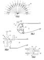
Figure 1 schematically shows a gas turbine engine. -
Figure 2 schematically shows a fuel injector array according to this application. -
Figure 3 shows one portion of theFigure 2 array. -
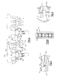
Figure 4 shows another portion. -
Figure 5 is a cross-sectional view along line 5-5 ofFigure 4 . -
Figure 6 shows the combined operation of theFigure 2 array. -
Figure 7 shows an alternative embodiment. -
Figure 8 is a view along line B-B ofFigure 7 . -
Figure 9 shows another alternative embodiment. - A
gas turbine engine 10, such as a turbofan gas turbine engine, circumferentially disposed about an engine centerline, oraxial centerline axis 12 is shown inFigure 1 . Theengine 10 includes afan 14,compressor sections combustion section 18 and aturbine section 20. As is well known in the art, air compressed in thecompressor 15/16 is mixed with fuel and burned in thecombustor 18 and expanded inturbine 20. Theturbine 20 includesrotors turbine 20 comprises alternating rows of rotary airfoils orblades 26 and static airfoils orvanes 28. In fact, this view is quite schematic, andblades 26 andvanes 28 are actually removable. It should be understood that this view is included simply to provide a basic understanding of the sections in a gas turbine engine, and not to limit the invention. This invention extends to all types of turbine engines for all types of applications. -
Figure 2 shows afuel injection array 40 which can be utilized with thecombustor 18 in a gas turbine engine. As shown, a plurality ofbluff body injectors 44 are circumferentially interspaced withswirler injectors 42. In one embodiment, there may be 16 of each type of injectors spaced around a central axis X of the gas turbine engine. Of course, other numbers can be used. - Swirlers are generally known, and one such device is shown in
Figure 3 . As shown inFigure 3 , theswirler injector 42 includes afuel injection pipe 46 injecting fuel into aswirler body 48. Swirlers are designed to provide air to mix with the fuel, such that the fuel and air are well mixed when they reach acombustion chamber 50. As shown,igniter 81 ignites the mixed fuel and air in thecombustion chamber 50. -
Figure 4 shows abluff body injector 44. Atube 54 receives fuel and directs the fuel outwardly to apilot port 56.Pilot opening 56 generally injects fuel into thecombustion chamber 50. Thepipe 54 also has a plurality ofopenings 58 which inject fuel into anair flow 52. As can be appreciated fromFigure 5 , theair flow 52 may be on both sides of thepipe 54, with theinjection 58 moving into theair flow 52 and being mixed prior to reaching thecombustion chamber 50. As shown, thepilot opening 56 injects the fuel directly into thecombustion chamber 50. -
Figure 6 shows a well mixed fuel/air zone which is provided when all of theinjectors pipes 54 havepilot openings 56 injecting fuel and having arecirculating area 86. Thepilot opening 56 provides a very stable and reliable flame. - Fuel is injected outwardly through
ports 58 and into theair flow 52 creating a portion of well mixedzone 100. The flame is held in thezones - The
swirler 42 is shown creating the other portion of well mixed fuel/air zone 100. The flame is held inzones 82 from the injectedfuel 80. - Returning to
Figures 3 and 4 , acontrol 300 is shown schematically associated with thepipe 54 and thefuel injector 46. Thecontrol 300 is operable to supply or block supply of fuel to thepipe 54 and theinjector 46. - The
injector array 40 is utilized in stages. Under low power operation, a first stage defined by thepilot openings 56 is utilized in combination with a second stage which is defined by the flow through theports 58. Thus, at idle, taxi, or sub-cruise operation, fuel is blocked through theswirlers 42 by thecontrol 300. - At take-off and cruise, a third stage is utilized in combination with the first two stages. The third stage includes the
swirlers 42. - The bluff body injector is particularly advantageous at lower power operation, as it provides the stable and reliable flame. A swirler is not as efficient at lower volume flow.
- On the other hand, using the several types of injectors at higher power provides benefits in that the swirlers provide excellent mixing. Further, the second stage injection would also provide good mixing. The use of the several distinct types of injection results in an overall combustion pattern that is not a coherent structure. If only a single type of injector is utilized, then the resultant combustion could act as a coherent structure, and result in an audio tone, which would be undesirable.
-
Figure 7 shows anotherembodiment bluff body 90. As shown, thefluid pipe 92 includes acentral passage 94 leading to thepilot opening 104.Side ports 96 operate as in earlier embodiments.Additional ports 98 supply fuel outwardly at a location upstream from theports 96.Air flow 102 mixes with all of the fuel from theports air passages 52 to create a well mixed fuel/air zone 100. - As can be appreciated from
Figure 8 , there are a great number ofports 98, ensuring increased mixing of the fuel withair - The use of the bluff body injector, and in particular the pilot opening ensures efficient and reliable combustion at the lower power operations On the other hand, the use of the swirler injectors at higher power operation ensure reduced smoke, or NOx emissions.
- At lower power operation, the amount of fuel flow in stage 2 is much greater than the amount of fuel flow from stage 1. At mid to high power operation, the amount of fuel flow from stage 3 can be optimized for emissions and combustion dynamics. The amount of fuel flow from stage 1.
-
Figure 9 shows an embodiment of aswirler 200 wherein a first supply offuel 202 extends to a location radially outwardly of themain injection point 204 to increase the level of fuel/air mixing. Air mixes with this fuel in the swirler body, as known. - Although embodiments of this invention have been disclosed, a worker of ordinary skill in this art would recognize that certain modifications would come within the scope of this invention. For that reason, the following claims should be studied to determine the true scope and content of this invention.
Claims (13)
- A fuel injection array (40) for a gas turbine engine (10) comprising:a plurality of bluff body injectors (44) and a plurality of swirler injectors (42);
anda control (300) for operating said plurality of bluff body injectors (44) and said swirler injectors (42) such that said bluff body injectors (44) are utilized without all of the swirler injectors (42) at least at low power operation and said swirler injectors (42) are utilized at higher power operation. - The fuel injection array (40) as set forth in claim 1, wherein said bluff body injectors (44) are utilized along with said swirler injectors (42) at higher power operation.
- The fuel injection array (40) as set forth in claim 1 or 2, wherein said bluff body injectors (44) include a central flow passage (94) leading to a pilot port (56; 104) communicating fuel into a combustion chamber (50).
- The fuel injection array (40) as set forth in claim 3, wherein said bluff body injectors (44) also communicate fuel into locations upstream of the combustion chamber (50) where the fuel is mixed with air (52) prior to it reaching the combustion chamber (50).
- The fuel injection array (40) as set forth in claim 4, wherein a fuel supply line (92) leads into said central flow passage (94), and ports (96) extend from said fuel supply line (92) to locations on opposed sides of said central flow passage (94) to intermix with air (52) flowing along said opposed sides.
- The fuel injection array (40) as set forth in claim 5, wherein fuel is directed in a plurality of directions from said ports (96).
- The fuel injection array (40) as set forth in claim 5 or 6, wherein fuel is directed from said fluid supply line (92) into said ports (96) at a plurality of locations including locations spaced more upstream from others of said locations.
- The fuel injection array (40) as set forth in any preceding claim, wherein said swirler injectors (42) include a fuel injector (200) delivering fuel at a radially outer location (202) and a radially inner location (204).
- The fuel injection array (40) as set forth in any preceding claim, wherein said bluff body injectors (44) and said swirler injectors (42) are circumferentially interspaced about a central axis (X).
- The fuel injection array (40) as set forth in any preceding claim, wherein said control (300) controls the flow of fuel to said bluff body injectors (44) and said swirler injectors (42).
- A method of injecting fuel and air into a gas turbine engine (10) comprising the steps of:injecting fuel from a bluff body injector (44) directly into a combustion chamber (50) at low power operation and not injecting fuel through associated swirler injectors (42) at low power operation; andinjecting fuel from said swirler injectors (42) to mix with air and then be directed into the combustion chamber (50) at higher power operation.
- The method as set forth in claim 11, wherein fuel is also injected from locations associated with said bluff body injectors (44) during low power operation.
- The method as set forth in claim 11 or 12, wherein fuel is also injected from said bluff body injectors (44) directly into the combustion chamber (50) at higher power operation.
Applications Claiming Priority (1)
| Application Number | Priority Date | Filing Date | Title |
|---|---|---|---|
| US13/170,406 US8950189B2 (en) | 2011-06-28 | 2011-06-28 | Gas turbine engine staged fuel injection using adjacent bluff body and swirler fuel injectors |
Publications (2)
| Publication Number | Publication Date |
|---|---|
| EP2541150A1 true EP2541150A1 (en) | 2013-01-02 |
| EP2541150B1 EP2541150B1 (en) | 2018-04-11 |
Family
ID=46331118
Family Applications (1)
| Application Number | Title | Priority Date | Filing Date |
|---|---|---|---|
| EP12173923.9A Not-in-force EP2541150B1 (en) | 2011-06-28 | 2012-06-27 | Gas turbine engine staged fuel injection |
Country Status (2)
| Country | Link |
|---|---|
| US (1) | US8950189B2 (en) |
| EP (1) | EP2541150B1 (en) |
Families Citing this family (1)
| Publication number | Priority date | Publication date | Assignee | Title |
|---|---|---|---|---|
| US20190301408A1 (en) * | 2018-04-02 | 2019-10-03 | Caterpillar Inc. | Combustion system for an internal combustion engine |
Citations (3)
| Publication number | Priority date | Publication date | Assignee | Title |
|---|---|---|---|---|
| US5099644A (en) * | 1990-04-04 | 1992-03-31 | General Electric Company | Lean staged combustion assembly |
| US5402634A (en) * | 1993-10-22 | 1995-04-04 | United Technologies Corporation | Fuel supply system for a staged combustor |
| US20020112482A1 (en) * | 2000-06-28 | 2002-08-22 | Johnson Arthur Wesley | Methods for decreasing combustor emissions |
Family Cites Families (11)
| Publication number | Priority date | Publication date | Assignee | Title |
|---|---|---|---|---|
| US5207064A (en) * | 1990-11-21 | 1993-05-04 | General Electric Company | Staged, mixed combustor assembly having low emissions |
| US5142858A (en) * | 1990-11-21 | 1992-09-01 | General Electric Company | Compact flameholder type combustor which is staged to reduce emissions |
| US5943866A (en) | 1994-10-03 | 1999-08-31 | General Electric Company | Dynamically uncoupled low NOx combustor having multiple premixers with axial staging |
| US5551869A (en) | 1995-03-07 | 1996-09-03 | Brais, Martres Et Associes Inc. | Gas staged burner |
| US6176087B1 (en) | 1997-12-15 | 2001-01-23 | United Technologies Corporation | Bluff body premixing fuel injector and method for premixing fuel and air |
| US6295801B1 (en) * | 1998-12-18 | 2001-10-02 | General Electric Company | Fuel injector bar for gas turbine engine combustor having trapped vortex cavity |
| US7621132B2 (en) | 2003-09-05 | 2009-11-24 | Delavan Inc. | Pilot combustor for stabilizing combustion in gas turbine engines |
| US7007477B2 (en) | 2004-06-03 | 2006-03-07 | General Electric Company | Premixing burner with impingement cooled centerbody and method of cooling centerbody |
| GB0625016D0 (en) | 2006-12-15 | 2007-01-24 | Rolls Royce Plc | Fuel injector |
| US8800290B2 (en) * | 2007-12-18 | 2014-08-12 | United Technologies Corporation | Combustor |
| US9068751B2 (en) * | 2010-01-29 | 2015-06-30 | United Technologies Corporation | Gas turbine combustor with staged combustion |
-
2011
- 2011-06-28 US US13/170,406 patent/US8950189B2/en active Active
-
2012
- 2012-06-27 EP EP12173923.9A patent/EP2541150B1/en not_active Not-in-force
Patent Citations (3)
| Publication number | Priority date | Publication date | Assignee | Title |
|---|---|---|---|---|
| US5099644A (en) * | 1990-04-04 | 1992-03-31 | General Electric Company | Lean staged combustion assembly |
| US5402634A (en) * | 1993-10-22 | 1995-04-04 | United Technologies Corporation | Fuel supply system for a staged combustor |
| US20020112482A1 (en) * | 2000-06-28 | 2002-08-22 | Johnson Arthur Wesley | Methods for decreasing combustor emissions |
Also Published As
| Publication number | Publication date |
|---|---|
| EP2541150B1 (en) | 2018-04-11 |
| US20130000311A1 (en) | 2013-01-03 |
| US8950189B2 (en) | 2015-02-10 |
Similar Documents
| Publication | Publication Date | Title |
|---|---|---|
| EP2481982B2 (en) | Mixer assembly for a gas turbine engine | |
| CN116293812B (en) | Fuel nozzle and swirler | |
| US9435537B2 (en) | System and method for premixer wake and vortex filling for enhanced flame-holding resistance | |
| US9182123B2 (en) | Combustor fuel nozzle and method for supplying fuel to a combustor | |
| CN103822228B (en) | Fuel nozzle and its assemble method | |
| US9182124B2 (en) | Gas turbine and fuel injector for the same | |
| EP2541148B1 (en) | Swirler for gas turbine engine fuel injector | |
| US11725819B2 (en) | Gas turbine fuel nozzle having a fuel passage within a swirler | |
| JP2004184072A (en) | Method and apparatus for reducing combustor emissions in a gas turbine engine | |
| EP1333228A3 (en) | Method and apparatus to decrease combustor emissions | |
| US20190003713A1 (en) | Air-shielded fuel injection assembly to facilitate reduced nox emissions in a combustor system | |
| US12152780B2 (en) | Method of supplying fuel and air to a combustor with an ignition tube | |
| EP3102887B1 (en) | Axial staged combustor with restricted main fuel injector | |
| US12072103B2 (en) | Turbine engine fuel premixer | |
| KR20100074102A (en) | Fuel control method and fuel control apparatus for gas turbine and gas turbine | |
| EP3425281B1 (en) | Pilot nozzle with inline premixing | |
| CN121296287A (en) | Gas turbine engine and its fuel nozzle assembly | |
| EP2541150B1 (en) | Gas turbine engine staged fuel injection | |
| US9316154B2 (en) | Gas turbine fuel injector with metering cavity | |
| Snyder | Gas Turbine Engine Staged Fuel Injection Using Adjacent Bluff Body and Swirler Fuel Injectors | |
| US20130152594A1 (en) | Gas turbine and fuel injector for the same | |
| EP4230916A2 (en) | Combustor with an ignition tube | |
| EP3043116A1 (en) | Mixer assembly for a gas turbine engine |
Legal Events
| Date | Code | Title | Description |
|---|---|---|---|
| PUAI | Public reference made under article 153(3) epc to a published international application that has entered the european phase |
Free format text: ORIGINAL CODE: 0009012 |
|
| AK | Designated contracting states |
Kind code of ref document: A1 Designated state(s): AL AT BE BG CH CY CZ DE DK EE ES FI FR GB GR HR HU IE IS IT LI LT LU LV MC MK MT NL NO PL PT RO RS SE SI SK SM TR |
|
| AX | Request for extension of the european patent |
Extension state: BA ME |
|
| 17P | Request for examination filed |
Effective date: 20130626 |
|
| RBV | Designated contracting states (corrected) |
Designated state(s): AL AT BE BG CH CY CZ DE DK EE ES FI FR GB GR HR HU IE IS IT LI LT LU LV MC MK MT NL NO PL PT RO RS SE SI SK SM TR |
|
| RAP1 | Party data changed (applicant data changed or rights of an application transferred) |
Owner name: UNITED TECHNOLOGIES CORPORATION |
|
| STAA | Information on the status of an ep patent application or granted ep patent |
Free format text: STATUS: EXAMINATION IS IN PROGRESS |
|
| 17Q | First examination report despatched |
Effective date: 20161208 |
|
| REG | Reference to a national code |
Ref country code: DE Ref legal event code: R079 Ref document number: 602012044971 Country of ref document: DE Free format text: PREVIOUS MAIN CLASS: F23R0003340000 Ipc: F23R0003140000 |
|
| GRAP | Despatch of communication of intention to grant a patent |
Free format text: ORIGINAL CODE: EPIDOSNIGR1 |
|
| STAA | Information on the status of an ep patent application or granted ep patent |
Free format text: STATUS: GRANT OF PATENT IS INTENDED |
|
| RIC1 | Information provided on ipc code assigned before grant |
Ipc: F23R 3/14 20060101AFI20170913BHEP Ipc: F23R 3/34 20060101ALI20170913BHEP |
|
| INTG | Intention to grant announced |
Effective date: 20171017 |
|
| GRAS | Grant fee paid |
Free format text: ORIGINAL CODE: EPIDOSNIGR3 |
|
| GRAA | (expected) grant |
Free format text: ORIGINAL CODE: 0009210 |
|
| STAA | Information on the status of an ep patent application or granted ep patent |
Free format text: STATUS: THE PATENT HAS BEEN GRANTED |
|
| AK | Designated contracting states |
Kind code of ref document: B1 Designated state(s): AL AT BE BG CH CY CZ DE DK EE ES FI FR GB GR HR HU IE IS IT LI LT LU LV MC MK MT NL NO PL PT RO RS SE SI SK SM TR |
|
| REG | Reference to a national code |
Ref country code: GB Ref legal event code: FG4D |
|
| REG | Reference to a national code |
Ref country code: CH Ref legal event code: EP |
|
| REG | Reference to a national code |
Ref country code: AT Ref legal event code: REF Ref document number: 988444 Country of ref document: AT Kind code of ref document: T Effective date: 20180415 |
|
| REG | Reference to a national code |
Ref country code: IE Ref legal event code: FG4D |
|
| REG | Reference to a national code |
Ref country code: DE Ref legal event code: R096 Ref document number: 602012044971 Country of ref document: DE |
|
| REG | Reference to a national code |
Ref country code: FR Ref legal event code: PLFP Year of fee payment: 7 |
|
| REG | Reference to a national code |
Ref country code: NL Ref legal event code: MP Effective date: 20180411 |
|
| REG | Reference to a national code |
Ref country code: LT Ref legal event code: MG4D |
|
| PG25 | Lapsed in a contracting state [announced via postgrant information from national office to epo] |
Ref country code: NL Free format text: LAPSE BECAUSE OF FAILURE TO SUBMIT A TRANSLATION OF THE DESCRIPTION OR TO PAY THE FEE WITHIN THE PRESCRIBED TIME-LIMIT Effective date: 20180411 |
|
| PG25 | Lapsed in a contracting state [announced via postgrant information from national office to epo] |
Ref country code: LT Free format text: LAPSE BECAUSE OF FAILURE TO SUBMIT A TRANSLATION OF THE DESCRIPTION OR TO PAY THE FEE WITHIN THE PRESCRIBED TIME-LIMIT Effective date: 20180411 Ref country code: PL Free format text: LAPSE BECAUSE OF FAILURE TO SUBMIT A TRANSLATION OF THE DESCRIPTION OR TO PAY THE FEE WITHIN THE PRESCRIBED TIME-LIMIT Effective date: 20180411 Ref country code: SE Free format text: LAPSE BECAUSE OF FAILURE TO SUBMIT A TRANSLATION OF THE DESCRIPTION OR TO PAY THE FEE WITHIN THE PRESCRIBED TIME-LIMIT Effective date: 20180411 Ref country code: NO Free format text: LAPSE BECAUSE OF FAILURE TO SUBMIT A TRANSLATION OF THE DESCRIPTION OR TO PAY THE FEE WITHIN THE PRESCRIBED TIME-LIMIT Effective date: 20180711 Ref country code: ES Free format text: LAPSE BECAUSE OF FAILURE TO SUBMIT A TRANSLATION OF THE DESCRIPTION OR TO PAY THE FEE WITHIN THE PRESCRIBED TIME-LIMIT Effective date: 20180411 Ref country code: AL Free format text: LAPSE BECAUSE OF FAILURE TO SUBMIT A TRANSLATION OF THE DESCRIPTION OR TO PAY THE FEE WITHIN THE PRESCRIBED TIME-LIMIT Effective date: 20180411 Ref country code: FI Free format text: LAPSE BECAUSE OF FAILURE TO SUBMIT A TRANSLATION OF THE DESCRIPTION OR TO PAY THE FEE WITHIN THE PRESCRIBED TIME-LIMIT Effective date: 20180411 Ref country code: BG Free format text: LAPSE BECAUSE OF FAILURE TO SUBMIT A TRANSLATION OF THE DESCRIPTION OR TO PAY THE FEE WITHIN THE PRESCRIBED TIME-LIMIT Effective date: 20180711 |
|
| PG25 | Lapsed in a contracting state [announced via postgrant information from national office to epo] |
Ref country code: LV Free format text: LAPSE BECAUSE OF FAILURE TO SUBMIT A TRANSLATION OF THE DESCRIPTION OR TO PAY THE FEE WITHIN THE PRESCRIBED TIME-LIMIT Effective date: 20180411 Ref country code: RS Free format text: LAPSE BECAUSE OF FAILURE TO SUBMIT A TRANSLATION OF THE DESCRIPTION OR TO PAY THE FEE WITHIN THE PRESCRIBED TIME-LIMIT Effective date: 20180411 Ref country code: GR Free format text: LAPSE BECAUSE OF FAILURE TO SUBMIT A TRANSLATION OF THE DESCRIPTION OR TO PAY THE FEE WITHIN THE PRESCRIBED TIME-LIMIT Effective date: 20180712 Ref country code: HR Free format text: LAPSE BECAUSE OF FAILURE TO SUBMIT A TRANSLATION OF THE DESCRIPTION OR TO PAY THE FEE WITHIN THE PRESCRIBED TIME-LIMIT Effective date: 20180411 |
|
| REG | Reference to a national code |
Ref country code: AT Ref legal event code: MK05 Ref document number: 988444 Country of ref document: AT Kind code of ref document: T Effective date: 20180411 |
|
| PG25 | Lapsed in a contracting state [announced via postgrant information from national office to epo] |
Ref country code: PT Free format text: LAPSE BECAUSE OF FAILURE TO SUBMIT A TRANSLATION OF THE DESCRIPTION OR TO PAY THE FEE WITHIN THE PRESCRIBED TIME-LIMIT Effective date: 20180813 |
|
| REG | Reference to a national code |
Ref country code: DE Ref legal event code: R097 Ref document number: 602012044971 Country of ref document: DE |
|
| PG25 | Lapsed in a contracting state [announced via postgrant information from national office to epo] |
Ref country code: AT Free format text: LAPSE BECAUSE OF FAILURE TO SUBMIT A TRANSLATION OF THE DESCRIPTION OR TO PAY THE FEE WITHIN THE PRESCRIBED TIME-LIMIT Effective date: 20180411 Ref country code: DK Free format text: LAPSE BECAUSE OF FAILURE TO SUBMIT A TRANSLATION OF THE DESCRIPTION OR TO PAY THE FEE WITHIN THE PRESCRIBED TIME-LIMIT Effective date: 20180411 Ref country code: SK Free format text: LAPSE BECAUSE OF FAILURE TO SUBMIT A TRANSLATION OF THE DESCRIPTION OR TO PAY THE FEE WITHIN THE PRESCRIBED TIME-LIMIT Effective date: 20180411 Ref country code: RO Free format text: LAPSE BECAUSE OF FAILURE TO SUBMIT A TRANSLATION OF THE DESCRIPTION OR TO PAY THE FEE WITHIN THE PRESCRIBED TIME-LIMIT Effective date: 20180411 Ref country code: EE Free format text: LAPSE BECAUSE OF FAILURE TO SUBMIT A TRANSLATION OF THE DESCRIPTION OR TO PAY THE FEE WITHIN THE PRESCRIBED TIME-LIMIT Effective date: 20180411 Ref country code: CZ Free format text: LAPSE BECAUSE OF FAILURE TO SUBMIT A TRANSLATION OF THE DESCRIPTION OR TO PAY THE FEE WITHIN THE PRESCRIBED TIME-LIMIT Effective date: 20180411 |
|
| REG | Reference to a national code |
Ref country code: CH Ref legal event code: PL |
|
| PLBE | No opposition filed within time limit |
Free format text: ORIGINAL CODE: 0009261 |
|
| STAA | Information on the status of an ep patent application or granted ep patent |
Free format text: STATUS: NO OPPOSITION FILED WITHIN TIME LIMIT |
|
| PG25 | Lapsed in a contracting state [announced via postgrant information from national office to epo] |
Ref country code: IT Free format text: LAPSE BECAUSE OF FAILURE TO SUBMIT A TRANSLATION OF THE DESCRIPTION OR TO PAY THE FEE WITHIN THE PRESCRIBED TIME-LIMIT Effective date: 20180411 Ref country code: SM Free format text: LAPSE BECAUSE OF FAILURE TO SUBMIT A TRANSLATION OF THE DESCRIPTION OR TO PAY THE FEE WITHIN THE PRESCRIBED TIME-LIMIT Effective date: 20180411 |
|
| REG | Reference to a national code |
Ref country code: BE Ref legal event code: MM Effective date: 20180630 |
|
| 26N | No opposition filed |
Effective date: 20190114 |
|
| PG25 | Lapsed in a contracting state [announced via postgrant information from national office to epo] |
Ref country code: LU Free format text: LAPSE BECAUSE OF NON-PAYMENT OF DUE FEES Effective date: 20180627 Ref country code: MC Free format text: LAPSE BECAUSE OF FAILURE TO SUBMIT A TRANSLATION OF THE DESCRIPTION OR TO PAY THE FEE WITHIN THE PRESCRIBED TIME-LIMIT Effective date: 20180411 |
|
| REG | Reference to a national code |
Ref country code: IE Ref legal event code: MM4A |
|
| PG25 | Lapsed in a contracting state [announced via postgrant information from national office to epo] |
Ref country code: IE Free format text: LAPSE BECAUSE OF NON-PAYMENT OF DUE FEES Effective date: 20180627 Ref country code: LI Free format text: LAPSE BECAUSE OF NON-PAYMENT OF DUE FEES Effective date: 20180630 Ref country code: CH Free format text: LAPSE BECAUSE OF NON-PAYMENT OF DUE FEES Effective date: 20180630 |
|
| PG25 | Lapsed in a contracting state [announced via postgrant information from national office to epo] |
Ref country code: SI Free format text: LAPSE BECAUSE OF FAILURE TO SUBMIT A TRANSLATION OF THE DESCRIPTION OR TO PAY THE FEE WITHIN THE PRESCRIBED TIME-LIMIT Effective date: 20180411 Ref country code: BE Free format text: LAPSE BECAUSE OF NON-PAYMENT OF DUE FEES Effective date: 20180630 |
|
| PG25 | Lapsed in a contracting state [announced via postgrant information from national office to epo] |
Ref country code: MT Free format text: LAPSE BECAUSE OF NON-PAYMENT OF DUE FEES Effective date: 20180627 |
|
| PG25 | Lapsed in a contracting state [announced via postgrant information from national office to epo] |
Ref country code: TR Free format text: LAPSE BECAUSE OF FAILURE TO SUBMIT A TRANSLATION OF THE DESCRIPTION OR TO PAY THE FEE WITHIN THE PRESCRIBED TIME-LIMIT Effective date: 20180411 |
|
| PG25 | Lapsed in a contracting state [announced via postgrant information from national office to epo] |
Ref country code: HU Free format text: LAPSE BECAUSE OF FAILURE TO SUBMIT A TRANSLATION OF THE DESCRIPTION OR TO PAY THE FEE WITHIN THE PRESCRIBED TIME-LIMIT; INVALID AB INITIO Effective date: 20120627 |
|
| PG25 | Lapsed in a contracting state [announced via postgrant information from national office to epo] |
Ref country code: CY Free format text: LAPSE BECAUSE OF FAILURE TO SUBMIT A TRANSLATION OF THE DESCRIPTION OR TO PAY THE FEE WITHIN THE PRESCRIBED TIME-LIMIT Effective date: 20180411 Ref country code: MK Free format text: LAPSE BECAUSE OF NON-PAYMENT OF DUE FEES Effective date: 20180411 |
|
| PG25 | Lapsed in a contracting state [announced via postgrant information from national office to epo] |
Ref country code: IS Free format text: LAPSE BECAUSE OF FAILURE TO SUBMIT A TRANSLATION OF THE DESCRIPTION OR TO PAY THE FEE WITHIN THE PRESCRIBED TIME-LIMIT Effective date: 20180811 |
|
| REG | Reference to a national code |
Ref country code: DE Ref legal event code: R081 Ref document number: 602012044971 Country of ref document: DE Owner name: RAYTHEON TECHNOLOGIES CORPORATION (N.D.GES.D.S, US Free format text: FORMER OWNER: UNITED TECHNOLOGIES CORPORATION, FARMINGTON, CONN., US |
|
| P01 | Opt-out of the competence of the unified patent court (upc) registered |
Effective date: 20230520 |
|
| PGFP | Annual fee paid to national office [announced via postgrant information from national office to epo] |
Ref country code: GB Payment date: 20240521 Year of fee payment: 13 |
|
| PGFP | Annual fee paid to national office [announced via postgrant information from national office to epo] |
Ref country code: DE Payment date: 20240521 Year of fee payment: 13 |
|
| PGFP | Annual fee paid to national office [announced via postgrant information from national office to epo] |
Ref country code: FR Payment date: 20240522 Year of fee payment: 13 |
|
| REG | Reference to a national code |
Ref country code: DE Ref legal event code: R119 Ref document number: 602012044971 Country of ref document: DE |
|
| GBPC | Gb: european patent ceased through non-payment of renewal fee |
Effective date: 20250627 |
|
| PG25 | Lapsed in a contracting state [announced via postgrant information from national office to epo] |
Ref country code: GB Free format text: LAPSE BECAUSE OF NON-PAYMENT OF DUE FEES Effective date: 20250627 |
|
| PG25 | Lapsed in a contracting state [announced via postgrant information from national office to epo] |
Ref country code: DE Free format text: LAPSE BECAUSE OF NON-PAYMENT OF DUE FEES Effective date: 20260101 |
|
| PG25 | Lapsed in a contracting state [announced via postgrant information from national office to epo] |
Ref country code: FR Free format text: LAPSE BECAUSE OF NON-PAYMENT OF DUE FEES Effective date: 20250630 |