EP2541005A1 - Exhaust Gas Control Apparatus for Internal Combustion Engine and Control Method for the Same - Google Patents
Exhaust Gas Control Apparatus for Internal Combustion Engine and Control Method for the Same Download PDFInfo
- Publication number
- EP2541005A1 EP2541005A1 EP12173852A EP12173852A EP2541005A1 EP 2541005 A1 EP2541005 A1 EP 2541005A1 EP 12173852 A EP12173852 A EP 12173852A EP 12173852 A EP12173852 A EP 12173852A EP 2541005 A1 EP2541005 A1 EP 2541005A1
- Authority
- EP
- European Patent Office
- Prior art keywords
- filter
- exhaust gas
- ashes
- amount
- wall surface
- Prior art date
- Legal status (The legal status is an assumption and is not a legal conclusion. Google has not performed a legal analysis and makes no representation as to the accuracy of the status listed.)
- Granted
Links
Images



Classifications
-
- F—MECHANICAL ENGINEERING; LIGHTING; HEATING; WEAPONS; BLASTING
- F01—MACHINES OR ENGINES IN GENERAL; ENGINE PLANTS IN GENERAL; STEAM ENGINES
- F01N—GAS-FLOW SILENCERS OR EXHAUST APPARATUS FOR MACHINES OR ENGINES IN GENERAL; GAS-FLOW SILENCERS OR EXHAUST APPARATUS FOR INTERNAL-COMBUSTION ENGINES
- F01N3/00—Exhaust or silencing apparatus having means for purifying, rendering innocuous, or otherwise treating exhaust
- F01N3/02—Exhaust or silencing apparatus having means for purifying, rendering innocuous, or otherwise treating exhaust for cooling, or for removing solid constituents of, exhaust
- F01N3/021—Exhaust or silencing apparatus having means for purifying, rendering innocuous, or otherwise treating exhaust for cooling, or for removing solid constituents of, exhaust by means of filters
- F01N3/023—Exhaust or silencing apparatus having means for purifying, rendering innocuous, or otherwise treating exhaust for cooling, or for removing solid constituents of, exhaust by means of filters using means for regenerating the filters, e.g. by burning trapped particles
-
- F—MECHANICAL ENGINEERING; LIGHTING; HEATING; WEAPONS; BLASTING
- F01—MACHINES OR ENGINES IN GENERAL; ENGINE PLANTS IN GENERAL; STEAM ENGINES
- F01N—GAS-FLOW SILENCERS OR EXHAUST APPARATUS FOR MACHINES OR ENGINES IN GENERAL; GAS-FLOW SILENCERS OR EXHAUST APPARATUS FOR INTERNAL-COMBUSTION ENGINES
- F01N2900/00—Details of electrical control or of the monitoring of the exhaust gas treating apparatus
- F01N2900/06—Parameters used for exhaust control or diagnosing
- F01N2900/16—Parameters used for exhaust control or diagnosing said parameters being related to the exhaust apparatus, e.g. particulate filter or catalyst
- F01N2900/1611—Particle filter ash amount
Definitions
- the invention relates to an exhaust gas control apparatus for an internal combustion engine and a control method for the same.
- JP-2007-23792 A there is known an apparatus that includes a filter that collects particulate matter (PM) in exhaust gas, as an exhaust gas control apparatus that is provided in an exhaust passage of an internal combustion engine.
- a filter that collects particulate matter (PM) in exhaust gas
- an exhaust gas control apparatus that is provided in an exhaust passage of an internal combustion engine.
- the pressure loss of the filter increases to adversely affect the output of the engine, and the like.
- a so-called recovery process for burning the collected PM by raising the temperature of the filter is carried out.
- a PM discharge amount per unit time and a PM oxidation amount per unit time are calculated to estimate a PM deposition amount in the filter.
- ashes which are components originating from lubricating oil and are difficult to burn through the aforementioned recovery process, are deposited in the filter.
- the oxidation speed of PM changes. Therefore, if the oxidation speed of the PM is calculated without taking the influence of the ashes into account, the accuracy of the oxidation speed becomes low. As a result, the accuracy in estimating the PM deposition amount in the filter decreases. When the accuracy in estimating the PM deposition amount thus decreases, burned embers of the PM may remain, for example, when the recovery process is completed.
- This invention provides an exhaust gas control apparatus for an internal combustion engine and a control method for the same, which make it possible to more accurately calculate a PM oxidation speed in a filter.
- a first aspect of the invention relates an exhaust gas control apparatus for an internal combustion engine.
- the exhaust gas control apparatus includes a filter that collects particulate matter in exhaust gas; and a control device that performs a recovery process for the filter.
- the control device calculates an oxidation speed of the particulate matter in the filter on a basis of a thickness of ashes deposited in the filter.
- the oxidation speed of the particulate matter in the filter namely, a PM oxidation speed is more greatly affected by the thickness of the ashes deposited in the filter than by the deposition amount of the ashes in the filter.
- the PM oxidation speed decreases even if the deposition amount itself of the ashes is small.
- the oxidation speed of the particulate matter is calculated on the basis of the thickness of the ashes deposited in the filter, and the PM oxidation speed in the filter can be accurately calculated.
- the control device may calculate the oxidation speed in a manner such that the oxidation speed is decreased as the thickness of the ashes deposited in the filter increases.
- the PM oxidation speed can be suitably calculated on the basis of the thickness of the ashes.
- the control device may calculate the thickness of the ashes deposited in the filter by calculating a deposition amount of the ashes in the filter, calculating a deposition density of the ashes on a basis of a maximum flow rate of exhaust gas, and dividing the deposition amount by a value that is obtained by multiplying a collection area of the filter by the deposition density.
- the ashes deposited in the filter are compressed due to the impetus of flowing exhaust gas.
- the density of the ashes deposited in the filter namely, the deposition density of the ashes can be calculated on the basis of the maximum flow rate of exhaust gas.
- the deposition density of the ashes is calculated on the basis of the maximum flow rate of exhaust gas.
- the deposition amount of the ashes is divided by the value that is obtained by multiplying the deposition density by the collection area of the filter.
- the thickness of the ashes deposited in the filter can be calculated.
- the deposition amount of ashes can be estimated from a difference between an exhaust gas pressure upstream of the filter and an exhaust gas pressure downstream of the filter after the completion of the recovery process, a consumption amount of a lubricating oil for the engine, or an operation time of the internal combustion engine, a running distance of the vehicle, or the like, which is correlated with the consumption amount of the lubricating oil for the engine.
- the control device may calculate a wall surface deposition amount that is an amount of ashes deposited on a wall surface of the filter in a radial direction of the filter, as the deposition amount of the ashes, and may set a collection area of the filter in the radial direction of the filter, as the collection area.
- ashes are deposited on the wall surface of the filter in the radial direction of the filter (that is, the wall surface of the filter in a sectional view of the filter taken along the radial direction of the filter), and on a bottom face of the filter that is located in a downstream side portion of the filter with respect to the flow of exhaust gas. It should be noted herein that since a larger amount of PM is collected on the wall surface of the filter in the radial direction of the filter than on the bottom face of the filter that is located in the downstream side portion of the filter with respect to the flow of exhaust gas, it is desirable to accurately calculate the PM oxidation speed on the wall surface of the filter.
- the wall surface deposition amount which is the amount of the ashes deposited on the wall surface of the filter in the radial direction of the filter
- the collection area of the filter in the radial direction of the filter (that is, the collection area on the wall surface of the filter in the radial direction of the filter) is set as the collection area.
- the thickness of the ashes deposited on the wall surface of the filter in the radial direction of the filter can be calculated.
- the PM oxidation speed is calculated on the basis of the thickness of the ashes deposited on the wall surface of the filter in the radial direction of the filter. Therefore, the PM oxidation speed on the wall surface of the filter in the radial direction of the filter can be accurately calculated.
- control device may calculate the wall surface deposition amount in a manner such that the wall surface deposition amount is decreased as a fluctuation amount of an exhaust gas flow rate increases.
- the ashes deposited on the wall surface of the filter in the radial direction of the filter are separated from the wall surface due to fluctuations in the exhaust gas flow rate, and are collected again on the bottom face of the filter that is located in the downstream side portion of the filter with respect to the flow of exhaust gas. Accordingly, as the fluctuation amount of the exhaust gas flow rate increases, the amount of the ashes separated from the wall surface of the filter in the radial direction of the filter increases, and the deposition amount of the ashes remaining on the wall surface decreases.
- the wall surface deposition amount of the ashes is calculated to decrease as the fluctuation amount of the exhaust gas flow rate increases. Accordingly, the wall surface deposition amount of the ashes can be appropriately estimated.
- the control device may measure the number of times that a fluctuation amount of an exhaust gas flow rate becomes larger than a predetermined value, and may calculate the wall surface deposition amount in a manner such that the wall surface deposition amount is decreased as the measured number of times increases.
- the ashes deposited on the wall surface of the filter in the radial direction of the filter are separated from the wall surface due to fluctuations in the exhaust gas flow rate, and are collected again on the bottom face of the filter that is located in the downstream side portion with respect to the flow of exhaust gas. Accordingly, as the number of times of fluctuation in the exhaust gas flow rate increases, the amount of the ashes separated from the wall surface of the filter in the radial direction of the filter increases, and the deposition amount of the ashes remaining on the wall surface decreases.
- the number of times that the fluctuation amount of the exhaust gas flow rate becomes larger than the predetermined value is measured, and the wall surface deposition amount of the ashes is calculated to decrease as the measured number of times increases. Accordingly, with this configuration as well, the wall surface deposition amount of the ashes can be appropriately estimated.
- the control device in order to calculate the wall surface deposition amount of ashes, may calculate a ratio of the amount of the ashes deposited on the wall surface to a total deposition amount of the ashes in the filter, and may calculate the wall surface deposition amount on a basis of the calculated ratio.
- the total deposition amount of the ashes can be estimated from a difference between an exhaust gas pressure upstream of the filter and an exhaust gas pressure downstream of the filter after the completion of the recovery process, a consumption amount of a lubricating oil for the engine, or an operation time of the internal combustion engine, a running distance of the vehicle, or the like, which is correlated with the consumption amount of the lubricating oil for the engine.
- the ratio of the deposition amount of the ashes on the wall surface can be set on the basis of the aforementioned fluctuation amount of the exhaust gas flow rate or the aforementioned number of times of fluctuation in the exhaust gas flow rate.
- a second aspect of the invention relates to a control method for an exhaust gas control apparatus for an internal combustion engine, the exhaust gas control apparatus including a filter that collects particulate matter in exhaust gas.
- the control method includes calculating an oxidation speed of the particulate matter in the filter on a basis of a thickness of ashes deposited in the filter; and performing a recovery process for the filter using the calculated oxidation speed.
- FIG. 1 is a schematic diagram showing a diesel engine (hereinafter referred to simply as "an engine") to which the exhaust gas control apparatus according to this embodiment of the invention is applied, and a peripheral configuration of the engine and the exhaust gas control apparatus.
- an engine a diesel engine (hereinafter referred to simply as "an engine") to which the exhaust gas control apparatus according to this embodiment of the invention is applied, and a peripheral configuration of the engine and the exhaust gas control apparatus.
- the engine 1 is provided with a plurality of cylinders #1 to #4.
- a cylinder head 2 is provided with a plurality of fuel injection valves 4a to 4d. These fuel injection valves 4a to 4d inject fuel into combustion chambers of the cylinders #1 to #4 respectively. Further, in the cylinder head 2, intake ports for introducing fresh air into the cylinders, and exhaust ports 6a to 6d for discharging combustion gas to the outside of the cylinders are provided for the cylinders #1 to #4 respectively.
- the fuel injection valves 4a to 4d are connected to a common rail 9 in which high-pressure fuel is accumulated.
- the common rail 9 is connected to a supply pump 10.
- the supply pump 10 sucks in fuel in a fuel tank, and supplies high-pressure fuel to the common rail 9.
- the high-pressure fuel supplied to the common rail 9 is injected from the fuel injection valves 4a to 4d into the cylinders respectively, when the fuel injection valves 4a to 4d are opened.
- An intake manifold 7 is connected to the intake ports.
- the intake manifold 7 is connected to an intake passage 3.
- An intake throttle valve 16 for adjusting the amount of intake air is provided in this intake passage 3.
- An exhaust manifold 8 is connected to the exhaust ports 6a to 6d.
- the exhaust manifold 8 is connected to an exhaust passage 26.
- a turbocharger 11 that supercharges intake air introduced into the cylinders with the aid of an exhaust gas pressure is provided in the exhaust passage 26.
- An intercooler 18 is provided in the intake passage 3 at a position between an intake-side compressor of the turbocharger 11 and the intake throttle valve 16. This intercooler 18 cools the intake air whose temperature has risen through the supercharging by the turbocharger 11.
- a converter 30 that purifies exhaust gas components is provided downstream of an exhaust-side turbine of the turbocharger 11.
- An oxidation catalyst 31 and a filter 32 are disposed in series with respect to the flow direction of exhaust gas, inside this converter 30.
- a catalyst that subjects HC in exhaust gas to an oxidation treatment is supported in the oxidation catalyst 31.
- the filter 32 is a member that collects particulate matter (PM) in exhaust gas, and is constituted by a porous ceramic.
- a catalyst for promoting the oxidation of PM is supported in this filter 32. The PM in exhaust gas is collected when passing through a porous wall of the filter 32.
- the cylinder head 2 is provided with a fuel addition valve 5 for supplying the oxidation catalyst 31 and the filter 32 with fuel as an addition agent.
- This fuel addition valve 5 is connected to the supply pump 10 via a fuel supply pipe 27, and fuel is injected from the fuel addition valve 5 toward the interior of the exhaust port 6d of the fourth cylinder #4. This injected fuel reaches the oxidation catalyst 31 and the filter 32 together with exhaust gas. It should be noted that the position at which the fuel addition valve 5 is disposed can be appropriately changed as long as the fuel addition valve 5 is located upstream of the converter 30 in an exhaust system.
- an exhaust gas recirculation device (hereinafter referred to as an EGR device).
- This EGR device is a device that introduces part of exhaust gas into intake air to lower the combustion temperature in the cylinders and hence reduce the generation amount of NOx.
- This exhaust gas recirculation device includes an EGR passage 13 as an exhaust gas recirculation passage through which the intake passage 3 and an exhaust passage (an exhaust manifold 8) communicate with each other, an EGR valve 15 that is provided in the EGR passage 13 to function as a flow rate control valve, an EGR cooler 14, and the like.
- the EGR cooler 14 lowers the temperature of the exhaust gas flowing in the EGR passage 13.
- the engine 1 is provided with various sensors for detecting an engine operation state.
- an airflow meter 19 detects an intake air amount GA in the intake passage 3.
- a throttle valve opening degree sensor 20 detects an opening degree of the intake throttle valve 16.
- An exhaust gas temperature sensor 33 which is provided downstream of the oxidation catalyst 31 with respect to the flow of exhaust gas, measures an exhaust gas temperature TE that is a temperature of the exhaust gas that has just passed through the oxidation catalyst 31.
- a differential pressure sensor 34 detects a pressure difference ⁇ P between an exhaust gas pressure upstream of the filter 32 with respect to the flow of exhaust gas and an exhaust gas pressure downstream of the filter 32 with respect to the flow of exhaust gas.
- An engine rotational speed sensor 23 detects a rotational speed of a crankshaft, namely, an engine rotational speed NE.
- An accelerator sensor 24 detects a depression amount of an accelerator pedal, namely, an accelerator operation amount ACCP.
- This control device 25 mainly includes a microcomputer that includes a central processing unit (a CPU), a read only memory (a ROM) in which various programs, maps and the like are stored in advance, a random access memory (a RAM) that temporarily stores a calculation result of the CPU or the like, a timer counter, an input interface, an output interface, and the like.
- a CPU central processing unit
- a ROM read only memory
- a RAM random access memory
- This control device 25 performs various kinds of control for the engine 1, for example, fuel injection amount control and fuel injection timing control for the fuel injection valves 4a to 4d and the fuel addition valve 5, discharge pressure control for the supply pump 10, drive amount control for an actuator 17 that opens/closes the intake throttle valve 16, opening degree control for the EGR valve 15, and the like. Further, the control device 25 performs various kinds of exhaust gas control, such as a recovery process for a filter that causes the PM collected by the aforementioned filter 32 to burn.
- a PM discharge amount PMe which is an amount of the PM that is discharged from all the combustion chambers of the engine 1, is calculated on the basis of a map that is set through an experiment conducted in advance or the like, for example, a PM discharge amount calculation map as shown in FIG. 2 , which uses a fuel injection amount Q of the fuel injection valves 4a to 4d and then engine rotational speed NE as parameters.
- the PM discharge amount PMe is calculated to increase as the engine rotational speed NE increases or as the fuel injection amount Q increases.
- This PM discharge amount PMe is repeatedly calculated on a predetermined cycle, and an accumulated value of the PM discharge amount PMe is calculated.
- a PM deposition amount PMsm which is an amount of the PM deposited in the filter 32, is estimated.
- the recovery process for the filter 32 is started.
- fuel is added by the aforementioned fuel addition valve 5.
- the fuel injected from this fuel addition valve 5 is burned upon reaching the oxidation catalyst 31, so that the temperature of exhaust gas is raised.
- the exhaust gas heated up in the oxidation catalyst 31 flows into the filter 32, so that the filter 32 is heated up.
- the PM deposited in the filter 32 is subjected to an oxidation treatment to recover the filter 32.
- a decrease amount of the PM resulting from the heat-up of the filter 32 namely, a PM deposition amount PMsm during recovery of the filter 32 is estimated on the basis of an expression (1) shown below.
- PMsm during the recovey process PMsm upon the start of the recovery process + PMe - PMc
- PMsm denotes a PM deposition amount
- PMe denotes a PM discharge amount
- PMc denotes a PM oxidation amount.
- the aforementioned PM oxidation amount PMc is an amount of the PM that is collected by the filter 32 and subjected to a combustion treatment.
- This PM oxidation amount PMc is calculated on the basis of a map that is set through an experiment conducted in advance or the like, for example, an oxidation speed map that indicates an oxidation amount of PM per unit time, or the like.
- the PM oxidation amount PMc and the PM discharge amount PMe are repeatedly calculated on a predetermined cycle, and the PM disposition amount PMsm is calculated according to the aforementioned expression (1) in synchronization with the calculation of those amounts.
- the PM deposition amount PMsm during the recovery process is estimated.
- the recovery process for the filter 32 is ended.
- the PM deposition amount PMsm in the filter 32 is reduced to a prescribed amount equivalent to the recovery end value PMf.
- Ashes which are components originating from lubricating oil and are difficult to burn through the aforementioned recovery process, are deposited in the filter 32.
- components contained in an addition agent and the like for lubricating oil metal components such as Zn, Ca, Mg, Na and the like
- Zn, Ca, Mg, Na and the like metal components such as Zn, Ca, Mg, Na and the like
- a PM oxidation speed PMcs changes. Therefore, when the PM oxidation speed PMcs is calculated without taking the influence of the ashes into account, the accuracy of the oxidation speed becomes low. That is, the discrepancy between an actual PM oxidation speed and the PM oxidation speed PMcs obtained from the aforementioned oxidation speed map increases.
- the accuracy in estimating the PM deposition amount PMsm in the filter 32 decreases.
- the recovery process is completed before the recovery end value PMf is reached. As a result, there may remain burned embers of the PM when the recovery process is completed.
- the inventor has found that the oxidation speed of the particulate matter in the filter 32, namely, the PM oxidation speed PMcs is more greatly affected by the thickness of the ashes deposited in the filter 32 than by the deposition amount of the ashes in the filter 32. More specifically, the inventor has found that the actual PM oxidation speed decreases as the thickness of the ashes deposited in the filter 32 increases. It is considered that the reason for the occurrence of this phenomenon is as follows. That is, it is considered that as the thickness of the ashes increases, the area of contact between the catalyst supported in the filter 32 and the PM decreases, the catalytic action decreases, and hence the oxidation speed of the,PM decreases.
- the PM oxidation speed PMcs is calculated on the basis of a thickness At of the ashes deposited in the filter 32, so that the PM oxidation speed PMcs is more accurately calculated.
- FIG. 3 shows a procedure of a processing of calculating the PM oxidation speed PMcs in this embodiment of the invention. It should be noted that this processing is repeatedly performed by the control device 25 on a predetermined cycle.
- a current ash deposition amount Asm is calculated (S100).
- the ash deposition amount Asm is calculated as follows. That is, as the deposition amount of ashes increases in the filter 32, the pressure difference ⁇ P detected by the differential pressure sensor 34 increases. Accordingly, the ash deposition amount Asm is estimated on the basis of the pressure difference ⁇ P.
- step S200 the density of the ashes deposited in the filter 32, namely, a deposition density Ad can be calculated on the basis of a maximum flow rate of exhaust gas.
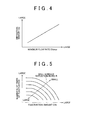
- the deposition density Ad which is the density of the ashes deposited in the filter 32, is calculated on the basis of a maximum flow rate EXmax of exhaust gas during the operation of the engine (S200).
- this deposition density Ad is calculated to increase as the maximum flow rate EXmax of exhaust gas increases.
- the maximum flow rate EXmax of exhaust gas is a maximum value of the flow rate of exhaust gas during the operation of the engine, and is updated as needed during the operation of the engine. Further, the flow rate of exhaust gas is estimated on the basis of an intake air amount, an engine load, an engine rotational speed, and the like.
- a wall surface deposition ratio R of the ashes is calculated on the basis of a fluctuation amount EXh of the exhaust gas flow rate and the number N of times of fluctuation in the exhaust gas flow rate (S300).
- the fluctuation amount EXh is an absolute value of a difference between a maximum value of the exhaust gas flow rate and a minimum value of the exhaust gas flow rate.
- the number N of times of fluctuation is the number of times of fluctuation in the exhaust gas flow rate, more specifically, the number of times that the aforementioned fluctuation amount EXh becomes larger than a predetermined value.
- the wall surface deposition ratio R of the ashes is a ratio of a wall surface deposition amount as an amount of the ashes deposited on a wall surface of the filter 32 in a radial direction of the filter 32 (that is, the wall surface of the filter 32 in a sectional view of the filter 32 taken along the radial direction of the filter 32, in other words, the wall surface extending in an axial direction of the filter 32) to a total deposition amount of the ashes in the filter 32 (the aforementioned ash deposition amount Asm).
- a value between "0" and "1" is set as this wall surface deposition ratio R.
- the wall surface deposition ratio R is set equal to "0". Further, in the case where all the ashes are deposited on the wall surface of the filter 32 in the radial direction of the filter 32, the wall surface deposition ratio R is set equal to "1".
- step S300 The process of step S300 is performed for the following reason.
- ashes are deposited on the wall surface of the filter 32 in the radial direction of the filter 32 and on the bottom face of the filter 32 that is located in a downstream side portion of the filter 32 with respect to the flow of exhaust gas.
- PM oxidation speed
- step S300 a ratio of the wall surface deposition amount of the ashes to the ash deposition amount Asm is first obtained.
- the ashes deposited on the wall surface of the filter 32 in the radial direction of the filter 32 are separated from the wall surface due to fluctuations in the exhaust gas flow rate, and are collected again on the bottom face of the filter 32 that is located in the downstream side portion of the filter 32 with respect to the flow of exhaust gas.
- the wall surface deposition ratio R is set to decrease as the fluctuation amount EXh of the exhaust gas flow rate increases.
- the ashes deposited on the wall surface of the filter 32 in the radial direction of the filter 32 are separated from the wall surface due to fluctuations in the exhaust gas flow rate, and are collected again on the bottom face of filter 32 that is located in the downstream side portion of the filter 32 with respect to the flow of exhaust gas. Accordingly, as the number N of times of fluctuation in the exhaust gas flow rate increases, the amount of the ashes separated from the wall surface of the filter 32 in the radial direction of the filter 32 increases, and the deposition amount of the ashes remaining on the wall surface decreases.
- the wall surface deposition ratio R is set to decrease as the number N of times of fluctuation in the exhaust gas flow rate increases.
- the wall surface deposition ratio R is variably set on the basis of the fluctuation amount EXh of the exhaust gas flow rate and the number N of times of fluctuation.
- the ash thickness At which is a thickness of the ashes deposited on the wall surface of the filter 32 in the radial direction of the filter 32, is calculated on the basis of the ash deposition amount Asm, the wall surface deposition ratio R, the deposition density Ad, and a collection area S for the PM in the radial direction of the filter 32 (that is, the collection area S on the wall surface of the filter 32 in the radial direction of the filter 32) (S400).
- the density of the ashes the deposition amount of the ashes / (the collection area for the ashes ⁇ the thickness of the ashes)
- the ash thickness At is calculated on the basis of an expression (2) shown below, which is obtained by transforming the relational expression.
- At Asm ⁇ R / Ad ⁇ S
- At denotes an ash thickness (mm)
- Asm denotes an ash deposition amount (g)
- R denotes a wall surface deposition ratio
- (AsmxR) denotes a total amount (g) of the ashes deposited on the wall surface of the filter 32 in the radial direction of the filter 32
- Ad denotes a deposition density (g/mm 3 ) of the ashes
- S denotes a collection area (mm 2 ) for the PM in the radial direction of the filter 32.
- the PM oxidation speed PMcs is calculated on the basis of the ash thickness At and the bed temperature T of the filter 32 (S500). It should be noted that the bed temperature T is estimated from the aforementioned exhaust gas temperature TE, which indicates a temperature of the exhaust gas flowing into the filter 32. Then in this step S500, an oxidation speed map shown in FIG. 6 is referred to. On the basis of this oxidation speed map, the PM oxidation speed PMcs is calculated to increase as the bed temperature T rises. Further, until the value of the ash thickness At reaches a predetermined value, the PM oxidation speed PMcs is calculated to decrease as the ash thickness At increases. Then, when the value of the ash thickness At exceeds the predetermined value described above, the PM oxidation speed PMcs is fixed to a certain value regardless of the value of the ash thickness At.
- the present processing is ended. Then, the PM deposition amount PMsm is estimated according to the aforementioned expression (1), through the use of the PM oxidation speed PMcs calculated in the present processing.
- the PM oxidation speed PMcs is set on the basis of the deposition thickness of the ashes (the ash thickness At) that affects the oxidation speed of the PM.
- the PM oxidation speed PMcs can be accurately calculated.
- the accuracy of the PM oxidation speed PMcs is enhanced, the accuracy in estimating the PM deposition amount PMsm according to the aforementioned expression (1) is also enhanced. Due to the enhancement of the accuracy in estimating the PM deposition amount PMsm, the timing for ending the recovery process is made appropriate. Therefore, it is possible to reduce the possibility that there are burned embers of the PM when the recovery process is completed.
- the ashes deposited in the filter 32 are compressed due to the impetus of flowing exhaust gas. Therefore, the density of the ashes deposited in the filter 32, namely, the deposition density of the ashes can be calculated on the basis of the maximum flow rate of exhaust gas.
- the deposition density Ad of the ashes is calculated on the basis of the maximum flow rate EXmax of exhaust gas. Then, the deposition amount of the ashes is divided by a value that is obtained by multiplying the deposition density Ad by the collection area of the filter 32, so that the thickness of the ashes deposited in the filter 32 can be calculated.
- the wall surface deposition amount which is the amount of the ashes deposited on the wall surface of the filter 32 in the radial direction of the filter 32, is calculated, and the collection area S of the filter 32 in the radial direction of the filter 32 is set as the collection area. Therefore, the thickness of the ashes deposited on the wall surface of the filter 32 in the radial direction of the filter 32 can be calculated. Then, the PM oxidation speed PMcs is set on the basis of the thickness of the ashes deposited on the wall surface of the filter 32 in the radial direction of the filter 32. Therefore, the PM oxidation speed PMcs on the wall surface of the filter 32 in the radial direction of the filter 32 can be accurately calculated.
- the ashes deposited on the wall surface of the filter 32 in the radial direction of the filter 32 are separated from the wall surface due to fluctuations in the exhaust gas flow rate, and are collected again on the bottom face of the filter 32 that is located in the downstream side portion of the filter 32 with respect to the flow of exhaust gas. Accordingly, as the fluctuation amount of the exhaust gas flow rate increases, the amount of the ashes separated from the wall surface of the filter 32 in the radial direction of the filter 32 increases, and the deposition amount of the ashes remaining on the wall surface decreases.
- the aforementioned wall surface deposition ratio R is calculated to decrease as the fluctuation amount of the exhaust gas flow rate increases. Accordingly, the wall surface deposition amount of the ashes can be appropriately estimated.
- the number of times of fluctuation in the exhaust gas flow rate increases, the amount of the ashes separated from the wall surface of the filter 32 in the radial direction of the filter 32 increases, and the deposition amount of the ashes remaining on the wall surface decreases.
- the number of times that the fluctuation amount EXh of the exhaust gas flow rate becomes larger than a predetermined value is measured, and the aforementioned wall surface deposition ratio R is calculated to decrease as the measured number of times increases. Accordingly, in this manner as well, the wall surface deposition amount of the ashes can be appropriately estimated.
- the PM oxidation speed PMcs in the filter 32 is calculated on the basis of the thickness of the ashes deposited in the filter 32.
- the PM oxidation speed PMcs is set on the basis of the thickness of the ashes deposited in the filter 32. More specifically, the PM oxidation speed PMcs is calculated to decrease as the thickness of the ashes deposited in the filter 32 increases. In other words, in the recovery process for the filter 32, the PM oxidation speed PMcs is variably set to decrease as the thickness of the ashes deposited in the filter 32 increases. Therefore, the PM oxidation speed PMcs in the filter 32 can be more accurately calculated.
- the ash deposition amount Asm in the filter 32 is calculated, the deposition density Ad of the ashes is calculated on the basis of the maximum flow rate EXmax of exhaust gas, and the ash deposition amount Asm is divided by a value that is obtained by multiplying the collection area of the filter 32 by the deposition density Ad. Therefore, the thickness of the ashes deposited in the filter 32 (the ash thickness At) can be calculated.
- the wall surface deposition amount which is the amount of the ashes deposited on the wall surface of the filter 32 in the radial direction of the filter 32, is calculated by multiplying the ash deposition amount Asm by the wall surface deposition ratio R, and the collection area S of the filter 32 in the radial direction of the filter 32 is set as the collection area of the filter 32. Therefore, the ash thickness At on the wall surface of the filter 32 on which a larger amount of PM is collected can be calculated. Thus, the PM oxidation speed PMcs on the wall surface of the filter 32 in the radial direction of the filter 32 can be accurately calculated.
- the wall surface deposition ratio R of ashes is set to decrease as the fluctuation amount EXh of the exhaust gas flow rate increases.
- the wall surface deposition amount of ashes is calculated to decrease as the fluctuation amount EXh of the exhaust gas flow rate increases. Accordingly, the wall surface deposition amount of ashes can be appropriately estimated.
- the number N of times of fluctuation which is the number of times that the fluctuation amount EXh of the exhaust gas flow rate becomes larger than the predetermined value, is measured, and the wall surface deposition ratio R of ashes is set to a value that decreases as the measured number N of times of fluctuation increases.
- the wall surface deposition amount of ashes is calculated to decrease as the number N of times of fluctuation in the exhaust gas flow rate increases. Accordingly, in this manner as well, the wall surface deposition amount of ashes can be appropriately estimated.
- the foregoing embodiment of the invention can also be implemented after being modified as follows.
- the aforementioned ashes originate from a lubricating oil for the engine 1, and the ash deposition amount Asm tends to increase as the consumption amount of the lubricating oil increases.
- the ash deposition amount Asm may be calculated on the basis of the consumption amount of the lubricating oil.
- the consumption amount of the lubricating oil can be determined by detecting the amount of the lubricating oil in an oil pan of the engine 1. Further, as the total running distance of the vehicle increases, the amount of the lubricating oil that has been consumed up to that time also increases.
- the consumption amount of the lubricating oil can also be estimated on the basis of the total running distance of the vehicle. Further, as the total operating time of the internal combustion engine increases, the amount of the lubricating oil that has been consumed up to that time also increases. Therefore, the consumption amount of the lubricating oil can also be estimated on the basis of the total operating time of the internal combustion engine, or the accumulated value of the fuel injection amount, which is correlated with the total operating time. In the case where the ash deposition amount Asm is calculated on the basis of the consumption amount of the lubricating oil as in this modified example, the ash deposition amount Asm is calculated to increase as the consumption amount increases. As a result, the ash deposition amount Asm can be appropriately calculated.
- the wall surface deposition ratio R is set on the basis of the fluctuation amount EXh of the exhaust gas flow rate and the number N of times of fluctuation in the exhaust gas flow rate. However, the wall surface deposition ratio R may be set on the basis of the fluctuation amount EXh of the exhaust gas flow rate alone or the number N of times of fluctuation in the exhaust gas flow rate alone.
- the ash thickness At on the wall surface of the filter 32 in the radial direction of the filter 32 is obtained. Also, the ash thickness At on the bottom face of the filter 32, which is located in the downstream side portion of the filter 32 with respect to the flow of exhaust gas, may be obtained, and the PM oxidation speed PMcs on the bottom face may be obtained on the basis of the map shown above in FIG. 6 or the like.
- the area of the bottom face of the filter 32, which is located in the downstream side portion of the filter 32 with respect to the flow of exhaust gas may be set as the collection area S in the aforementioned expression (2), and the ash thickness At on the bottom face may be calculated on the basis of an expression (3) shown below, which is obtained by transforming part of the expression (2).
- At Asm ⁇ 1 - R / Ad ⁇ S
- Asm denotes an ash thickness (mm) on the bottom face
- Asm denotes an ash deposition amount (g)
- R denotes a wall surface deposition ratio
- Asm ⁇ (1-R) denotes a total amount (g) of the ashes deposited on the bottom face of the filter 32
- Ad denotes a deposition density (g/mm 3 ) of ashes
- S denotes a collection area (mm 2 ) for the PM on the bottom face of the filter 32.
- the accuracy in estimating the PM oxidation speed PMcs on the bottom face of the filter 32 can be enhanced.
- the ash thickness At on the wall surface of the filter 32 in the radial direction of the filter 32 is obtained.
- an average of the ash thickness At in the filter 32 may be obtained, and the average PM oxidation speed PMcs in the filter 32 may be obtained on the basis of that average and the map shown above in FIG. 6 or the like.
- an entire collection area of the filter 32 may be set as the collection area S in the aforementioned expression (2), and an average of the ash thickness At in the filter 32 may be calculated on the basis of an expression (4) shown below, which is obtained by transforming part of the expression (2).
- At Asm / Ad ⁇ S
- At an average (mm) of the ash thickness
- Asm denotes an ash deposition amount (g)
- Ad denotes a deposition density (g/mm 3 ) of ashes
- S denotes an entire collection area (mm 2 ) for the PM in the filter 32.
- Fuel for heating up the filter 32 is supplied from the fuel addition valve 5. Also, the filter 32 may be heated up by carrying out post injection (fuel injection that is carried out again at a timing later than a timing at which main injection is carried out) by the fuel injection valves 4a to 4d. Further, the supply of fuel by the fuel addition valve 5 and the supply of fuel through post injection may be performed in a compatible manner.
- the aforementioned addition agent is fuel for the engine 1.
- any addition agent may be used as long as a similar effect can be obtained.
- the number of catalysts or filters disposed in the converter 30 can be arbitrarily set.
- the invention is also applicable in the same manner to an exhaust gas control apparatus which includes the filter 32 and does not include the oxidation catalyst 31, and in which the temperature of the filter 32 is raised by oxidizing the fuel on the filter 32.
- the aforementioned engine 1 is an inline four-cylinder internal combustion engine.
- the invention is also applicable in the same manner to an exhaust gas control apparatus for an internal combustion engine that includes one, two, three, five or more cylinders or has its cylinders arranged in a different manner.
Landscapes
- Engineering & Computer Science (AREA)
- Chemical & Material Sciences (AREA)
- Combustion & Propulsion (AREA)
- Mechanical Engineering (AREA)
- General Engineering & Computer Science (AREA)
- Processes For Solid Components From Exhaust (AREA)
- Filtering Of Dispersed Particles In Gases (AREA)
- Exhaust Gas Treatment By Means Of Catalyst (AREA)
Abstract
Description
- The invention relates to an exhaust gas control apparatus for an internal combustion engine and a control method for the same.
- As described in Japanese Patent Application Publication No.
2007-23792 JP-2007-23792 A - In this recovery process, when the amount of the PM deposited in the filter reaches a preset amount, an addition agent such as fuel is supplied to the exhaust passage. Then, the filter is heated up due to the combustion of the addition agent, and the oxidation of the PM in the filter is thereby promoted. As a result, the amount of the PM deposited in the filter decreases to a prescribed amount.
- In the apparatus that carries out the recovery process as described above, a PM discharge amount per unit time and a PM oxidation amount per unit time are calculated to estimate a PM deposition amount in the filter.
- As described in the aforementioned Japanese Patent Application Publication No.
2007-23792 JP-2007-23792 A - This invention provides an exhaust gas control apparatus for an internal combustion engine and a control method for the same, which make it possible to more accurately calculate a PM oxidation speed in a filter.
- A first aspect of the invention relates an exhaust gas control apparatus for an internal combustion engine. The exhaust gas control apparatus includes a filter that collects particulate matter in exhaust gas; and a control device that performs a recovery process for the filter. The control device calculates an oxidation speed of the particulate matter in the filter on a basis of a thickness of ashes deposited in the filter.
- The inventor has found that the oxidation speed of the particulate matter in the filter, namely, a PM oxidation speed is more greatly affected by the thickness of the ashes deposited in the filter than by the deposition amount of the ashes in the filter. For example, in the case where the density of the ashes (the mass of the ashes per unit volume) is small and the thickness of the deposited ashes is large, the PM oxidation speed decreases even if the deposition amount itself of the ashes is small.
- Thus, in this configuration, the oxidation speed of the particulate matter is calculated on the basis of the thickness of the ashes deposited in the filter, and the PM oxidation speed in the filter can be accurately calculated.
- The inventor has confirmed that the actual PM oxidation speed decreases as the thickness of the ashes deposited in the filter increases. Thus, in the foregoing aspect of the invention, the control device may calculate the oxidation speed in a manner such that the oxidation speed is decreased as the thickness of the ashes deposited in the filter increases. By adopting this configuration, the PM oxidation speed can be suitably calculated on the basis of the thickness of the ashes.
- In the exhaust gas control apparatus according to the foregoing aspect of the invention, the control device may calculate the thickness of the ashes deposited in the filter by calculating a deposition amount of the ashes in the filter, calculating a deposition density of the ashes on a basis of a maximum flow rate of exhaust gas, and dividing the deposition amount by a value that is obtained by multiplying a collection area of the filter by the deposition density.
- The ashes deposited in the filter are compressed due to the impetus of flowing exhaust gas. Thus, the density of the ashes deposited in the filter, namely, the deposition density of the ashes can be calculated on the basis of the maximum flow rate of exhaust gas. Thus, in this configuration, the deposition density of the ashes is calculated on the basis of the maximum flow rate of exhaust gas. Then, the deposition amount of the ashes is divided by the value that is obtained by multiplying the deposition density by the collection area of the filter. Thus, the thickness of the ashes deposited in the filter can be calculated.
- It should be noted that the deposition amount of ashes can be estimated from a difference between an exhaust gas pressure upstream of the filter and an exhaust gas pressure downstream of the filter after the completion of the recovery process, a consumption amount of a lubricating oil for the engine, or an operation time of the internal combustion engine, a running distance of the vehicle, or the like, which is correlated with the consumption amount of the lubricating oil for the engine.
- In the exhaust gas control apparatus according to the foregoing aspect of the invention, the control device may calculate a wall surface deposition amount that is an amount of ashes deposited on a wall surface of the filter in a radial direction of the filter, as the deposition amount of the ashes, and may set a collection area of the filter in the radial direction of the filter, as the collection area.
- In the filter, ashes are deposited on the wall surface of the filter in the radial direction of the filter (that is, the wall surface of the filter in a sectional view of the filter taken along the radial direction of the filter), and on a bottom face of the filter that is located in a downstream side portion of the filter with respect to the flow of exhaust gas. It should be noted herein that since a larger amount of PM is collected on the wall surface of the filter in the radial direction of the filter than on the bottom face of the filter that is located in the downstream side portion of the filter with respect to the flow of exhaust gas, it is desirable to accurately calculate the PM oxidation speed on the wall surface of the filter.
- In this respect, according to this configuration, the wall surface deposition amount, which is the amount of the ashes deposited on the wall surface of the filter in the radial direction of the filter, is calculated, and the collection area of the filter in the radial direction of the filter (that is, the collection area on the wall surface of the filter in the radial direction of the filter) is set as the collection area. Thus, the thickness of the ashes deposited on the wall surface of the filter in the radial direction of the filter can be calculated. Then, the PM oxidation speed is calculated on the basis of the thickness of the ashes deposited on the wall surface of the filter in the radial direction of the filter. Therefore, the PM oxidation speed on the wall surface of the filter in the radial direction of the filter can be accurately calculated.
- In the exhaust gas control apparatus according to the foregoing aspect of the invention, the control device may calculate the wall surface deposition amount in a manner such that the wall surface deposition amount is decreased as a fluctuation amount of an exhaust gas flow rate increases.
- The ashes deposited on the wall surface of the filter in the radial direction of the filter are separated from the wall surface due to fluctuations in the exhaust gas flow rate, and are collected again on the bottom face of the filter that is located in the downstream side portion of the filter with respect to the flow of exhaust gas. Accordingly, as the fluctuation amount of the exhaust gas flow rate increases, the amount of the ashes separated from the wall surface of the filter in the radial direction of the filter increases, and the deposition amount of the ashes remaining on the wall surface decreases. Thus, in this configuration, the wall surface deposition amount of the ashes is calculated to decrease as the fluctuation amount of the exhaust gas flow rate increases. Accordingly, the wall surface deposition amount of the ashes can be appropriately estimated.
- In the exhaust gas control apparatus according to the foregoing aspect of the invention, the control device may measure the number of times that a fluctuation amount of an exhaust gas flow rate becomes larger than a predetermined value, and may calculate the wall surface deposition amount in a manner such that the wall surface deposition amount is decreased as the measured number of times increases.
- As described above, the ashes deposited on the wall surface of the filter in the radial direction of the filter are separated from the wall surface due to fluctuations in the exhaust gas flow rate, and are collected again on the bottom face of the filter that is located in the downstream side portion with respect to the flow of exhaust gas. Accordingly, as the number of times of fluctuation in the exhaust gas flow rate increases, the amount of the ashes separated from the wall surface of the filter in the radial direction of the filter increases, and the deposition amount of the ashes remaining on the wall surface decreases. Thus, in this configuration, the number of times that the fluctuation amount of the exhaust gas flow rate becomes larger than the predetermined value is measured, and the wall surface deposition amount of the ashes is calculated to decrease as the measured number of times increases. Accordingly, with this configuration as well, the wall surface deposition amount of the ashes can be appropriately estimated.
- In the exhaust gas control apparatus according to the foregoing aspect of the invention, in order to calculate the wall surface deposition amount of ashes, the control device may calculate a ratio of the amount of the ashes deposited on the wall surface to a total deposition amount of the ashes in the filter, and may calculate the wall surface deposition amount on a basis of the calculated ratio. It should be noted that, in this configuration, the total deposition amount of the ashes can be estimated from a difference between an exhaust gas pressure upstream of the filter and an exhaust gas pressure downstream of the filter after the completion of the recovery process, a consumption amount of a lubricating oil for the engine, or an operation time of the internal combustion engine, a running distance of the vehicle, or the like, which is correlated with the consumption amount of the lubricating oil for the engine. Further, the ratio of the deposition amount of the ashes on the wall surface can be set on the basis of the aforementioned fluctuation amount of the exhaust gas flow rate or the aforementioned number of times of fluctuation in the exhaust gas flow rate.
- A second aspect of the invention relates to a control method for an exhaust gas control apparatus for an internal combustion engine, the exhaust gas control apparatus including a filter that collects particulate matter in exhaust gas. The control method includes calculating an oxidation speed of the particulate matter in the filter on a basis of a thickness of ashes deposited in the filter; and performing a recovery process for the filter using the calculated oxidation speed.
- Features, advantages, and technical and industrial significance of an exemplary embodiment of the invention will be described below with reference to the accompanying drawings, in which like numerals denote like elements, and wherein:
-
FIG. 1 is a schematic diagram showing an internal combustion engine to which an exhaust gas control apparatus for an internal combustion engine according to an embodiment of the invention is applied, and a peripheral configuration of the internal combustion engine and the exhaust gas control apparatus; -
FIG. 2 is a graph showing a relationship between an engine rotational speed and a PM discharge amount, and a relationship between a fuel injection amount and the PM discharge amount; -
FIG. 3 is a flowchart showing a procedure of a processing of calculating a PM oxidation speed; -
FIG. 4 is a graph showing a relationship between a maximum flow rate of exhaust gas and a deposition density of ashes; -
FIG. 5 is a graph showing a relationship between a fluctuation amount of an exhaust gas flow rate and a wall surface deposition ratio, and a relationship between the number of times of fluctuation in the exhaust gas flow rate and the wall surface deposition ratio; and -
FIG. 6 is a graph showing a relationship among a bed temperature of a filter, a thickness of the ashes, and the PM oxidation speed. - Hereinafter, an exhaust gas control apparatus for an internal combustion engine according to an embodiment of this invention will be described with reference to
FIGS. 1 to 6 .FIG. 1 is a schematic diagram showing a diesel engine (hereinafter referred to simply as "an engine") to which the exhaust gas control apparatus according to this embodiment of the invention is applied, and a peripheral configuration of the engine and the exhaust gas control apparatus. - The
engine 1 is provided with a plurality ofcylinders # 1 to #4. Acylinder head 2 is provided with a plurality offuel injection valves 4a to 4d. Thesefuel injection valves 4a to 4d inject fuel into combustion chambers of thecylinders # 1 to #4 respectively. Further, in thecylinder head 2, intake ports for introducing fresh air into the cylinders, andexhaust ports 6a to 6d for discharging combustion gas to the outside of the cylinders are provided for thecylinders # 1 to #4 respectively. - The
fuel injection valves 4a to 4d are connected to acommon rail 9 in which high-pressure fuel is accumulated. Thecommon rail 9 is connected to asupply pump 10. Thesupply pump 10 sucks in fuel in a fuel tank, and supplies high-pressure fuel to thecommon rail 9. The high-pressure fuel supplied to thecommon rail 9 is injected from thefuel injection valves 4a to 4d into the cylinders respectively, when thefuel injection valves 4a to 4d are opened. - An
intake manifold 7 is connected to the intake ports. Theintake manifold 7 is connected to anintake passage 3. Anintake throttle valve 16 for adjusting the amount of intake air is provided in thisintake passage 3. - An
exhaust manifold 8 is connected to theexhaust ports 6a to 6d. Theexhaust manifold 8 is connected to anexhaust passage 26. Aturbocharger 11 that supercharges intake air introduced into the cylinders with the aid of an exhaust gas pressure is provided in theexhaust passage 26. Anintercooler 18 is provided in theintake passage 3 at a position between an intake-side compressor of theturbocharger 11 and theintake throttle valve 16. Thisintercooler 18 cools the intake air whose temperature has risen through the supercharging by theturbocharger 11. - Further, in the
exhaust passage 26, aconverter 30 that purifies exhaust gas components is provided downstream of an exhaust-side turbine of theturbocharger 11. Anoxidation catalyst 31 and afilter 32 are disposed in series with respect to the flow direction of exhaust gas, inside thisconverter 30. - A catalyst that subjects HC in exhaust gas to an oxidation treatment is supported in the
oxidation catalyst 31. Further, thefilter 32 is a member that collects particulate matter (PM) in exhaust gas, and is constituted by a porous ceramic. A catalyst for promoting the oxidation of PM is supported in thisfilter 32. The PM in exhaust gas is collected when passing through a porous wall of thefilter 32. - Further, the
cylinder head 2 is provided with afuel addition valve 5 for supplying theoxidation catalyst 31 and thefilter 32 with fuel as an addition agent. Thisfuel addition valve 5 is connected to thesupply pump 10 via afuel supply pipe 27, and fuel is injected from thefuel addition valve 5 toward the interior of theexhaust port 6d of thefourth cylinder # 4. This injected fuel reaches theoxidation catalyst 31 and thefilter 32 together with exhaust gas. It should be noted that the position at which thefuel addition valve 5 is disposed can be appropriately changed as long as thefuel addition valve 5 is located upstream of theconverter 30 in an exhaust system. - In addition, the
engine 1 is equipped with an exhaust gas recirculation device (hereinafter referred to as an EGR device). This EGR device is a device that introduces part of exhaust gas into intake air to lower the combustion temperature in the cylinders and hence reduce the generation amount of NOx. This exhaust gas recirculation device includes anEGR passage 13 as an exhaust gas recirculation passage through which theintake passage 3 and an exhaust passage (an exhaust manifold 8) communicate with each other, anEGR valve 15 that is provided in theEGR passage 13 to function as a flow rate control valve, anEGR cooler 14, and the like. Through the adjustment of the opening degree of theEGR valve 15, the recirculation amount of the exhaust gas introduced from theexhaust passage 26 into theintake passage 3, namely, an EGR amount is regulated. Further, theEGR cooler 14 lowers the temperature of the exhaust gas flowing in theEGR passage 13. - The
engine 1 is provided with various sensors for detecting an engine operation state. For example, anairflow meter 19 detects an intake air amount GA in theintake passage 3. A throttle valveopening degree sensor 20 detects an opening degree of theintake throttle valve 16. An exhaustgas temperature sensor 33, which is provided downstream of theoxidation catalyst 31 with respect to the flow of exhaust gas, measures an exhaust gas temperature TE that is a temperature of the exhaust gas that has just passed through theoxidation catalyst 31. Adifferential pressure sensor 34 detects a pressure difference ΔP between an exhaust gas pressure upstream of thefilter 32 with respect to the flow of exhaust gas and an exhaust gas pressure downstream of thefilter 32 with respect to the flow of exhaust gas. An enginerotational speed sensor 23 detects a rotational speed of a crankshaft, namely, an engine rotational speed NE. Anaccelerator sensor 24 detects a depression amount of an accelerator pedal, namely, an accelerator operation amount ACCP. - Outputs of these various sensors are input to a
control device 25. Thiscontrol device 25 mainly includes a microcomputer that includes a central processing unit (a CPU), a read only memory (a ROM) in which various programs, maps and the like are stored in advance, a random access memory (a RAM) that temporarily stores a calculation result of the CPU or the like, a timer counter, an input interface, an output interface, and the like. - This
control device 25 performs various kinds of control for theengine 1, for example, fuel injection amount control and fuel injection timing control for thefuel injection valves 4a to 4d and thefuel addition valve 5, discharge pressure control for thesupply pump 10, drive amount control for anactuator 17 that opens/closes theintake throttle valve 16, opening degree control for theEGR valve 15, and the like. Further, thecontrol device 25 performs various kinds of exhaust gas control, such as a recovery process for a filter that causes the PM collected by theaforementioned filter 32 to burn. - The recovery process for the
aforementioned filter 32 is basically carried out as follows. First, a PM discharge amount PMe, which is an amount of the PM that is discharged from all the combustion chambers of theengine 1, is calculated on the basis of a map that is set through an experiment conducted in advance or the like, for example, a PM discharge amount calculation map as shown inFIG. 2 , which uses a fuel injection amount Q of thefuel injection valves 4a to 4d and then engine rotational speed NE as parameters. It should be noted that, as shown inFIG. 2 , the PM discharge amount PMe is calculated to increase as the engine rotational speed NE increases or as the fuel injection amount Q increases. This PM discharge amount PMe is repeatedly calculated on a predetermined cycle, and an accumulated value of the PM discharge amount PMe is calculated. Thus, a PM deposition amount PMsm, which is an amount of the PM deposited in thefilter 32, is estimated. - Then, when the PM deposition amount PMsm thus calculated reaches a recovery start value PMstart, the recovery process for the
filter 32 is started. In this recovery process, fuel is added by the aforementionedfuel addition valve 5. The fuel injected from thisfuel addition valve 5 is burned upon reaching theoxidation catalyst 31, so that the temperature of exhaust gas is raised. Then, the exhaust gas heated up in theoxidation catalyst 31 flows into thefilter 32, so that thefilter 32 is heated up. Thus, the PM deposited in thefilter 32 is subjected to an oxidation treatment to recover thefilter 32. - A decrease amount of the PM resulting from the heat-up of the
filter 32, namely, a PM deposition amount PMsm during recovery of thefilter 32 is estimated on the basis of an expression (1) shown below.
filter 32 and subjected to a combustion treatment. This PM oxidation amount PMc is calculated on the basis of a map that is set through an experiment conducted in advance or the like, for example, an oxidation speed map that indicates an oxidation amount of PM per unit time, or the like. The PM oxidation amount PMc and the PM discharge amount PMe are repeatedly calculated on a predetermined cycle, and the PM disposition amount PMsm is calculated according to the aforementioned expression (1) in synchronization with the calculation of those amounts. Thus, the PM deposition amount PMsm during the recovery process is estimated. - When the PM deposition amount PMsm during the recovery process, which is thus estimated, becomes small enough to fall below a predetermined recovery end value PMf, the recovery process for the
filter 32 is ended. Thus, the PM deposition amount PMsm in thefilter 32 is reduced to a prescribed amount equivalent to the recovery end value PMf. - Ashes, which are components originating from lubricating oil and are difficult to burn through the aforementioned recovery process, are deposited in the
filter 32. It should be noted that components contained in an addition agent and the like for lubricating oil (metal components such as Zn, Ca, Mg, Na and the like) can be mentioned as examples of these ashes. When these ashes are deposited in thefilter 32, a PM oxidation speed PMcs changes. Therefore, when the PM oxidation speed PMcs is calculated without taking the influence of the ashes into account, the accuracy of the oxidation speed becomes low. That is, the discrepancy between an actual PM oxidation speed and the PM oxidation speed PMcs obtained from the aforementioned oxidation speed map increases. When the accuracy of the PM oxidation speed PMcs thus becomes low, the accuracy in estimating the PM deposition amount PMsm in thefilter 32 decreases. When the accuracy in estimating the PM deposition amount PMsm thus decreases, the recovery process is completed before the recovery end value PMf is reached. As a result, there may remain burned embers of the PM when the recovery process is completed. - In this situation, the inventor has found that the oxidation speed of the particulate matter in the
filter 32, namely, the PM oxidation speed PMcs is more greatly affected by the thickness of the ashes deposited in thefilter 32 than by the deposition amount of the ashes in thefilter 32. More specifically, the inventor has found that the actual PM oxidation speed decreases as the thickness of the ashes deposited in thefilter 32 increases. It is considered that the reason for the occurrence of this phenomenon is as follows. That is, it is considered that as the thickness of the ashes increases, the area of contact between the catalyst supported in thefilter 32 and the PM decreases, the catalytic action decreases, and hence the oxidation speed of the,PM decreases. - Thus, in this embodiment of the invention, the PM oxidation speed PMcs is calculated on the basis of a thickness At of the ashes deposited in the
filter 32, so that the PM oxidation speed PMcs is more accurately calculated. -
FIG. 3 shows a procedure of a processing of calculating the PM oxidation speed PMcs in this embodiment of the invention. It should be noted that this processing is repeatedly performed by thecontrol device 25 on a predetermined cycle. When this processing is started, a current ash deposition amount Asm is calculated (S100). In this case, the ash deposition amount Asm is calculated as follows. That is, as the deposition amount of ashes increases in thefilter 32, the pressure difference ΔP detected by thedifferential pressure sensor 34 increases. Accordingly, the ash deposition amount Asm is estimated on the basis of the pressure difference ΔP. - Subsequently, the ashes deposited in the
filter 32 are compressed due to impetus of flowing exhaust gas. Therefore, the density of the ashes deposited in thefilter 32, namely, a deposition density Ad can be calculated on the basis of a maximum flow rate of exhaust gas. Thus, in step S200 that follows step S100, the deposition density Ad, which is the density of the ashes deposited in thefilter 32, is calculated on the basis of a maximum flow rate EXmax of exhaust gas during the operation of the engine (S200). In this step S200, as shown inFIG. 4 , this deposition density Ad is calculated to increase as the maximum flow rate EXmax of exhaust gas increases. It should be noted that the maximum flow rate EXmax of exhaust gas is a maximum value of the flow rate of exhaust gas during the operation of the engine, and is updated as needed during the operation of the engine. Further, the flow rate of exhaust gas is estimated on the basis of an intake air amount, an engine load, an engine rotational speed, and the like. - Subsequently, a wall surface deposition ratio R of the ashes is calculated on the basis of a fluctuation amount EXh of the exhaust gas flow rate and the number N of times of fluctuation in the exhaust gas flow rate (S300). The fluctuation amount EXh is an absolute value of a difference between a maximum value of the exhaust gas flow rate and a minimum value of the exhaust gas flow rate. Further, the number N of times of fluctuation is the number of times of fluctuation in the exhaust gas flow rate, more specifically, the number of times that the aforementioned fluctuation amount EXh becomes larger than a predetermined value. This fluctuation amount EXh and this number N of times of fluctuation are measured during the recovery process for the
filter 32 and are stored in a storage unit of thecontrol device 25, and are read from the storage unit of thecontrol device 25 when the present processing is performed. The wall surface deposition ratio R of the ashes is a ratio of a wall surface deposition amount as an amount of the ashes deposited on a wall surface of thefilter 32 in a radial direction of the filter 32 (that is, the wall surface of thefilter 32 in a sectional view of thefilter 32 taken along the radial direction of thefilter 32, in other words, the wall surface extending in an axial direction of the filter 32) to a total deposition amount of the ashes in the filter 32 (the aforementioned ash deposition amount Asm). A value between "0" and "1" is set as this wall surface deposition ratio R. In the case where all the ashes are deposited on a bottom face of thefilter 32, the wall surface deposition ratio R is set equal to "0". Further, in the case where all the ashes are deposited on the wall surface of thefilter 32 in the radial direction of thefilter 32, the wall surface deposition ratio R is set equal to "1". - The process of step S300 is performed for the following reason. In the
filter 32, first, ashes are deposited on the wall surface of thefilter 32 in the radial direction of thefilter 32 and on the bottom face of thefilter 32 that is located in a downstream side portion of thefilter 32 with respect to the flow of exhaust gas. It should be noted herein that since a larger amount of PM is collected on the wall surface of thefilter 32 in the radial direction of thefilter 32 than on the bottom face of thefilter 32 that is located in the downstream side portion of thefilter 32 with respect to the flow of exhaust gas, it is desirable to accurately calculate the PM oxidation speed PMcs on the wall surface of thefilter 32 in the radial direction of thefilter 32. - Thus, in step S300, a ratio of the wall surface deposition amount of the ashes to the ash deposition amount Asm is first obtained. It should be noted herein that the ashes deposited on the wall surface of the
filter 32 in the radial direction of thefilter 32 are separated from the wall surface due to fluctuations in the exhaust gas flow rate, and are collected again on the bottom face of thefilter 32 that is located in the downstream side portion of thefilter 32 with respect to the flow of exhaust gas. Accordingly, as the fluctuation amount EXh of the exhaust gas flow rate increases, the amount of the ashes separated from the wall surface of thefilter 32 in the radial direction of thefilter 32 increases, and the deposition amount of the ashes remaining on the wall surface decreases. Thus, as shown inFIG. 5 , the wall surface deposition ratio R is set to decrease as the fluctuation amount EXh of the exhaust gas flow rate increases. - Further, as described above, the ashes deposited on the wall surface of the
filter 32 in the radial direction of thefilter 32 are separated from the wall surface due to fluctuations in the exhaust gas flow rate, and are collected again on the bottom face offilter 32 that is located in the downstream side portion of thefilter 32 with respect to the flow of exhaust gas. Accordingly, as the number N of times of fluctuation in the exhaust gas flow rate increases, the amount of the ashes separated from the wall surface of thefilter 32 in the radial direction of thefilter 32 increases, and the deposition amount of the ashes remaining on the wall surface decreases. Thus, as shown above inFIG. 5 , the wall surface deposition ratio R is set to decrease as the number N of times of fluctuation in the exhaust gas flow rate increases. - In this manner, the wall surface deposition ratio R is variably set on the basis of the fluctuation amount EXh of the exhaust gas flow rate and the number N of times of fluctuation. Subsequently, the ash thickness At, which is a thickness of the ashes deposited on the wall surface of the
filter 32 in the radial direction of thefilter 32, is calculated on the basis of the ash deposition amount Asm, the wall surface deposition ratio R, the deposition density Ad, and a collection area S for the PM in the radial direction of the filter 32 (that is, the collection area S on the wall surface of thefilter 32 in the radial direction of the filter 32) (S400). In this case, since there is established a relational expression, the density of the ashes = the deposition amount of the ashes / (the collection area for the ashes × the thickness of the ashes), the ash thickness At is calculated on the basis of an expression (2) shown below, which is obtained by transforming the relational expression.
In the expression (2), At denotes an ash thickness (mm), Asm denotes an ash deposition amount (g), R denotes a wall surface deposition ratio, (AsmxR) denotes a total amount (g) of the ashes deposited on the wall surface of thefilter 32 in the radial direction of thefilter 32, Ad denotes a deposition density (g/mm3) of the ashes, and S denotes a collection area (mm2) for the PM in the radial direction of thefilter 32. - Subsequently, the PM oxidation speed PMcs is calculated on the basis of the ash thickness At and the bed temperature T of the filter 32 (S500). It should be noted that the bed temperature T is estimated from the aforementioned exhaust gas temperature TE, which indicates a temperature of the exhaust gas flowing into the
filter 32. Then in this step S500, an oxidation speed map shown inFIG. 6 is referred to. On the basis of this oxidation speed map, the PM oxidation speed PMcs is calculated to increase as the bed temperature T rises. Further, until the value of the ash thickness At reaches a predetermined value, the PM oxidation speed PMcs is calculated to decrease as the ash thickness At increases. Then, when the value of the ash thickness At exceeds the predetermined value described above, the PM oxidation speed PMcs is fixed to a certain value regardless of the value of the ash thickness At. - When the PM oxidation speed PMcs is thus calculated, the present processing is ended. Then, the PM deposition amount PMsm is estimated according to the aforementioned expression (1), through the use of the PM oxidation speed PMcs calculated in the present processing.
- Next, the advantageous effects of this embodiment of the invention will be described. As described above, in this embodiment of the invention, based on the knowledge of the inventor, the PM oxidation speed PMcs is set on the basis of the deposition thickness of the ashes (the ash thickness At) that affects the oxidation speed of the PM. Thus, the PM oxidation speed PMcs can be accurately calculated. When the accuracy of the PM oxidation speed PMcs is enhanced, the accuracy in estimating the PM deposition amount PMsm according to the aforementioned expression (1) is also enhanced. Due to the enhancement of the accuracy in estimating the PM deposition amount PMsm, the timing for ending the recovery process is made appropriate. Therefore, it is possible to reduce the possibility that there are burned embers of the PM when the recovery process is completed.
- Further, the ashes deposited in the
filter 32 are compressed due to the impetus of flowing exhaust gas. Therefore, the density of the ashes deposited in thefilter 32, namely, the deposition density of the ashes can be calculated on the basis of the maximum flow rate of exhaust gas. Thus, the deposition density Ad of the ashes is calculated on the basis of the maximum flow rate EXmax of exhaust gas. Then, the deposition amount of the ashes is divided by a value that is obtained by multiplying the deposition density Ad by the collection area of thefilter 32, so that the thickness of the ashes deposited in thefilter 32 can be calculated. In this case, in particular, the wall surface deposition amount, which is the amount of the ashes deposited on the wall surface of thefilter 32 in the radial direction of thefilter 32, is calculated, and the collection area S of thefilter 32 in the radial direction of thefilter 32 is set as the collection area. Therefore, the thickness of the ashes deposited on the wall surface of thefilter 32 in the radial direction of thefilter 32 can be calculated. Then, the PM oxidation speed PMcs is set on the basis of the thickness of the ashes deposited on the wall surface of thefilter 32 in the radial direction of thefilter 32. Therefore, the PM oxidation speed PMcs on the wall surface of thefilter 32 in the radial direction of thefilter 32 can be accurately calculated. - Further, the ashes deposited on the wall surface of the
filter 32 in the radial direction of thefilter 32 are separated from the wall surface due to fluctuations in the exhaust gas flow rate, and are collected again on the bottom face of thefilter 32 that is located in the downstream side portion of thefilter 32 with respect to the flow of exhaust gas. Accordingly, as the fluctuation amount of the exhaust gas flow rate increases, the amount of the ashes separated from the wall surface of thefilter 32 in the radial direction of thefilter 32 increases, and the deposition amount of the ashes remaining on the wall surface decreases. Thus, the aforementioned wall surface deposition ratio R is calculated to decrease as the fluctuation amount of the exhaust gas flow rate increases. Accordingly, the wall surface deposition amount of the ashes can be appropriately estimated. - Further, as the number of times of fluctuation in the exhaust gas flow rate increases, the amount of the ashes separated from the wall surface of the
filter 32 in the radial direction of thefilter 32 increases, and the deposition amount of the ashes remaining on the wall surface decreases. Thus, the number of times that the fluctuation amount EXh of the exhaust gas flow rate becomes larger than a predetermined value is measured, and the aforementioned wall surface deposition ratio R is calculated to decrease as the measured number of times increases. Accordingly, in this manner as well, the wall surface deposition amount of the ashes can be appropriately estimated. - As described above, the following advantageous effects can be obtained according to this embodiment of the invention. (1) The PM oxidation speed PMcs in the
filter 32 is calculated on the basis of the thickness of the ashes deposited in thefilter 32. In other words, in the recovery process for thefilter 32, the PM oxidation speed PMcs is set on the basis of the thickness of the ashes deposited in thefilter 32. More specifically, the PM oxidation speed PMcs is calculated to decrease as the thickness of the ashes deposited in thefilter 32 increases. In other words, in the recovery process for thefilter 32, the PM oxidation speed PMcs is variably set to decrease as the thickness of the ashes deposited in thefilter 32 increases. Therefore, the PM oxidation speed PMcs in thefilter 32 can be more accurately calculated. - (2) Because the PM oxidation speed PMcs is accurately calculated, the accuracy in estimating the PM deposition amount PMsm is enhanced. Therefore, it is possible to reduce the possibility that there are burned embers of the PM when the recovery process is completed.
- (3) The ash deposition amount Asm in the
filter 32 is calculated, the deposition density Ad of the ashes is calculated on the basis of the maximum flow rate EXmax of exhaust gas, and the ash deposition amount Asm is divided by a value that is obtained by multiplying the collection area of thefilter 32 by the deposition density Ad. Therefore, the thickness of the ashes deposited in the filter 32 (the ash thickness At) can be calculated. In particular, the wall surface deposition amount, which is the amount of the ashes deposited on the wall surface of thefilter 32 in the radial direction of thefilter 32, is calculated by multiplying the ash deposition amount Asm by the wall surface deposition ratio R, and the collection area S of thefilter 32 in the radial direction of thefilter 32 is set as the collection area of thefilter 32. Therefore, the ash thickness At on the wall surface of thefilter 32 on which a larger amount of PM is collected can be calculated. Thus, the PM oxidation speed PMcs on the wall surface of thefilter 32 in the radial direction of thefilter 32 can be accurately calculated. - (4) The wall surface deposition ratio R of ashes is set to decrease as the fluctuation amount EXh of the exhaust gas flow rate increases. Thus, the wall surface deposition amount of ashes is calculated to decrease as the fluctuation amount EXh of the exhaust gas flow rate increases. Accordingly, the wall surface deposition amount of ashes can be appropriately estimated.
- (5) The number N of times of fluctuation, which is the number of times that the fluctuation amount EXh of the exhaust gas flow rate becomes larger than the predetermined value, is measured, and the wall surface deposition ratio R of ashes is set to a value that decreases as the measured number N of times of fluctuation increases. Thus, the wall surface deposition amount of ashes is calculated to decrease as the number N of times of fluctuation in the exhaust gas flow rate increases. Accordingly, in this manner as well, the wall surface deposition amount of ashes can be appropriately estimated.
- It should be noted that the foregoing embodiment of the invention can also be implemented after being modified as follows. The aforementioned ashes originate from a lubricating oil for the
engine 1, and the ash deposition amount Asm tends to increase as the consumption amount of the lubricating oil increases. Thus, the ash deposition amount Asm may be calculated on the basis of the consumption amount of the lubricating oil. It should be noted that the consumption amount of the lubricating oil can be determined by detecting the amount of the lubricating oil in an oil pan of theengine 1. Further, as the total running distance of the vehicle increases, the amount of the lubricating oil that has been consumed up to that time also increases. Therefore, the consumption amount of the lubricating oil can also be estimated on the basis of the total running distance of the vehicle. Further, as the total operating time of the internal combustion engine increases, the amount of the lubricating oil that has been consumed up to that time also increases. Therefore, the consumption amount of the lubricating oil can also be estimated on the basis of the total operating time of the internal combustion engine, or the accumulated value of the fuel injection amount, which is correlated with the total operating time. In the case where the ash deposition amount Asm is calculated on the basis of the consumption amount of the lubricating oil as in this modified example, the ash deposition amount Asm is calculated to increase as the consumption amount increases. As a result, the ash deposition amount Asm can be appropriately calculated. - The wall surface deposition ratio R is set on the basis of the fluctuation amount EXh of the exhaust gas flow rate and the number N of times of fluctuation in the exhaust gas flow rate. However, the wall surface deposition ratio R may be set on the basis of the fluctuation amount EXh of the exhaust gas flow rate alone or the number N of times of fluctuation in the exhaust gas flow rate alone.
- The ash thickness At on the wall surface of the
filter 32 in the radial direction of thefilter 32 is obtained. Also, the ash thickness At on the bottom face of thefilter 32, which is located in the downstream side portion of thefilter 32 with respect to the flow of exhaust gas, may be obtained, and the PM oxidation speed PMcs on the bottom face may be obtained on the basis of the map shown above inFIG. 6 or the like. In this modification example, the area of the bottom face of thefilter 32, which is located in the downstream side portion of thefilter 32 with respect to the flow of exhaust gas, may be set as the collection area S in the aforementioned expression (2), and the ash thickness At on the bottom face may be calculated on the basis of an expression (3) shown below, which is obtained by transforming part of the expression (2).
filter 32, Ad denotes a deposition density (g/mm3) of ashes, and S denotes a collection area (mm2) for the PM on the bottom face of thefilter 32. According to this modification example, the accuracy in estimating the PM oxidation speed PMcs on the bottom face of thefilter 32 can be enhanced. - In the foregoing embodiment of the invention, the ash thickness At on the wall surface of the
filter 32 in the radial direction of thefilter 32 is obtained. However, an average of the ash thickness At in thefilter 32 may be obtained, and the average PM oxidation speed PMcs in thefilter 32 may be obtained on the basis of that average and the map shown above inFIG. 6 or the like. In this modification example, an entire collection area of thefilter 32 may be set as the collection area S in the aforementioned expression (2), and an average of the ash thickness At in thefilter 32 may be calculated on the basis of an expression (4) shown below, which is obtained by transforming part of the expression (2).
filter 32. - Fuel for heating up the
filter 32 is supplied from thefuel addition valve 5. Also, thefilter 32 may be heated up by carrying out post injection (fuel injection that is carried out again at a timing later than a timing at which main injection is carried out) by thefuel injection valves 4a to 4d. Further, the supply of fuel by thefuel addition valve 5 and the supply of fuel through post injection may be performed in a compatible manner. - The aforementioned addition agent is fuel for the
engine 1. However, any addition agent may be used as long as a similar effect can be obtained. The number of catalysts or filters disposed in theconverter 30 can be arbitrarily set. For example, the invention is also applicable in the same manner to an exhaust gas control apparatus which includes thefilter 32 and does not include theoxidation catalyst 31, and in which the temperature of thefilter 32 is raised by oxidizing the fuel on thefilter 32. - The
aforementioned engine 1 is an inline four-cylinder internal combustion engine. However, the invention is also applicable in the same manner to an exhaust gas control apparatus for an internal combustion engine that includes one, two, three, five or more cylinders or has its cylinders arranged in a different manner.
Claims (12)
- An exhaust gas control apparatus for an internal combustion engine, characterized by comprising:a filter (32) that collects particulate matter in exhaust gas; anda control device (25) that performs a recovery process for the filter (32), whereinthe control device (25) calculates an oxidation speed of the particulate matter in the filter (32) on a basis of a thickness of ashes deposited in the filter (32).
- The exhaust gas control apparatus according to claim 1, wherein the control device (25) calculates the oxidation speed in a manner such that the oxidation speed is decreased as the thickness of the ashes deposited in the filter (32) increases.
- The exhaust gas control apparatus according to claim 1 or 2, wherein the control device (25) calculates the thickness of the ashes deposited in the filter (32) by calculating a deposition amount of the ashes in the filter (32), calculating a deposition density of the ashes on a basis of a maximum flow rate of exhaust gas, and dividing the deposition amount by a value that is obtained by multiplying a collection area of the filter (32) by the deposition density.
- The exhaust gas control apparatus according to claim 3, wherein the control device (25) calculates a wall surface deposition amount that is an amount of ashes deposited on a wall surface of the filter (32) in a radial direction of the filter (32), as the deposition amount of the ashes, and sets a collection area of the filter (32) in the radial direction of the filter (32), as the collection area.
- The exhaust gas control apparatus according to claim 4, wherein the control device (25) calculates the wall surface deposition amount in a manner such that the wall surface deposition amount is decreased as a fluctuation amount of an exhaust gas flow rate increases.
- The exhaust gas control apparatus according to claim 4, wherein the control device (25) measures the number of times that a fluctuation amount of an exhaust gas flow rate becomes larger than a predetermined value, and calculates the wall surface deposition amount in a manner such that the wall surface deposition amount is decreased as the measured number of times increases.
- The exhaust gas control apparatus according to any one of claims 4 to 6, wherein the control device (25) calculates a ratio of the amount of the ashes deposited on the wall surface to a total deposition amount of the ashes in the filter (32), and calculates the wall surface deposition amount on a basis of the calculated ratio.
- The exhaust gas control apparatus according to any one of claims 1 to 7, wherein the control device (25) calculates the oxidation speed of the particulate matter on a basis of the thickness of the ashes deposited in the filter (32) and a bed temperature of the filter (32).
- The exhaust gas control apparatus according to any one of claims 1 to 8, wherein the control device (25) calculates a deposition amount of the particulate matter in the filter (32) using the calculated oxidation speed during the recovery process, and ends the recovery process when the calculated deposition amount of the particulate matter becomes smaller than a predetermined recovery end value.
- A control method for an exhaust gas control apparatus for an internal combustion engine, the exhaust gas control apparatus including a filter (32) that collects particulate matter in exhaust gas, characterized by comprising:calculating an oxidation speed of the particulate matter in the filter (32) on a basis of a thickness of ashes deposited in the filter (32); andperforming a recovery process for the filter (32) using the calculated oxidation speed.
- The control method according to claim 10, wherein the oxidation speed is calculated to decrease as the thickness of the ashes deposited in the filter (32) increases.
- The control method according to claim 10 or 11, wherein a deposition amount of the particulate matter in the filter (32) is calculated using the calculated oxidation speed during the recovery process, and the recovery process is ended when the calculated deposition amount of the particulate matter becomes smaller than a predetermined recovery end value.
Applications Claiming Priority (1)
| Application Number | Priority Date | Filing Date | Title |
|---|---|---|---|
| JP2011144262A JP5287940B2 (en) | 2011-06-29 | 2011-06-29 | Exhaust gas purification device for internal combustion engine |
Publications (2)
| Publication Number | Publication Date |
|---|---|
| EP2541005A1 true EP2541005A1 (en) | 2013-01-02 |
| EP2541005B1 EP2541005B1 (en) | 2015-03-04 |
Family
ID=46458205
Family Applications (1)
| Application Number | Title | Priority Date | Filing Date |
|---|---|---|---|
| EP20120173852 Not-in-force EP2541005B1 (en) | 2011-06-29 | 2012-06-27 | Exhaust Gas Control Apparatus for Internal Combustion Engine and Control Method for the Same |
Country Status (2)
| Country | Link |
|---|---|
| EP (1) | EP2541005B1 (en) |
| JP (1) | JP5287940B2 (en) |
Families Citing this family (1)
| Publication number | Priority date | Publication date | Assignee | Title |
|---|---|---|---|---|
| JP6866814B2 (en) * | 2017-09-21 | 2021-04-28 | トヨタ自動車株式会社 | Exhaust purification device |
Citations (3)
| Publication number | Priority date | Publication date | Assignee | Title |
|---|---|---|---|---|
| EP1672204A1 (en) * | 2004-12-16 | 2006-06-21 | Nissan Motor Co., Ltd. | Internal combustion engine having an exhaust particulate filter |
| JP2007023792A (en) | 2005-07-12 | 2007-02-01 | Toyota Industries Corp | Exhaust emission control device |
| EP1832727A2 (en) * | 2006-03-07 | 2007-09-12 | Nissan Motor Ltd. | An apparatus and a method for detection of particulate matter accumulation |
Family Cites Families (4)
| Publication number | Priority date | Publication date | Assignee | Title |
|---|---|---|---|---|
| JP2003049630A (en) * | 2001-08-07 | 2003-02-21 | Toyota Motor Corp | Exhaust gas purification apparatus and exhaust gas purification method |
| JP2006274983A (en) * | 2005-03-30 | 2006-10-12 | Mitsubishi Fuso Truck & Bus Corp | Exhaust emission control device |
| JP2008297912A (en) * | 2007-05-29 | 2008-12-11 | Toyota Motor Corp | Lubricating oil amount estimation device for internal combustion engine |
| JP5263307B2 (en) * | 2011-01-13 | 2013-08-14 | 日産自動車株式会社 | Exhaust gas purification filter regeneration start timing control device and regeneration start timing control method |
-
2011
- 2011-06-29 JP JP2011144262A patent/JP5287940B2/en not_active Expired - Fee Related
-
2012
- 2012-06-27 EP EP20120173852 patent/EP2541005B1/en not_active Not-in-force
Patent Citations (3)
| Publication number | Priority date | Publication date | Assignee | Title |
|---|---|---|---|---|
| EP1672204A1 (en) * | 2004-12-16 | 2006-06-21 | Nissan Motor Co., Ltd. | Internal combustion engine having an exhaust particulate filter |
| JP2007023792A (en) | 2005-07-12 | 2007-02-01 | Toyota Industries Corp | Exhaust emission control device |
| EP1832727A2 (en) * | 2006-03-07 | 2007-09-12 | Nissan Motor Ltd. | An apparatus and a method for detection of particulate matter accumulation |
Also Published As
| Publication number | Publication date |
|---|---|
| JP2013011224A (en) | 2013-01-17 |
| JP5287940B2 (en) | 2013-09-11 |
| EP2541005B1 (en) | 2015-03-04 |
Similar Documents
| Publication | Publication Date | Title |
|---|---|---|
| JP4111094B2 (en) | Control device and control method for supercharged engine with exhaust aftertreatment device | |
| JP4453739B2 (en) | Control method of addition valve | |
| US20120180463A1 (en) | Diesel engine | |
| WO2010133276A1 (en) | Method for calculating an efficiency index of a diesel oxidation catalyst | |
| JP2005098290A (en) | Exhaust gas purification device for internal combustion engine | |
| JP2009174368A (en) | Exhaust gas purification device for internal combustion engine | |
| JP2010112220A (en) | Catalyst diagnostic device | |
| JP4211611B2 (en) | Exhaust gas purification device for internal combustion engine | |
| JP2010196498A (en) | Pm emission estimation device | |
| JP5834773B2 (en) | Exhaust gas purification device for internal combustion engine | |
| WO2013073326A1 (en) | Dpf pm accumulation quantity estimation device | |
| JP2012197681A (en) | Exhaust gas recirculation system for engine device | |
| EP2541005B1 (en) | Exhaust Gas Control Apparatus for Internal Combustion Engine and Control Method for the Same | |
| JP2011231645A (en) | Exhaust emission control device for internal combustion engine | |
| JP6939688B2 (en) | Exhaust treatment system | |
| EP1722088A2 (en) | Exhaust gas treatment system for internal combustion engine | |
| AU2014333505B2 (en) | Exhaust gas control apparatus for an internal combustion engine and corresponding control method | |
| EP2677150A2 (en) | Exhaust gas control apparatus of internal combustion engine | |
| EP2721263B1 (en) | Exhaust gas control apparatus for internal combustion engine | |
| JP2008215110A (en) | Exhaust gas purification device for internal combustion engine | |
| AU2014333505A1 (en) | Exhaust gas control apparatus for an internal combustion engine and corresponding control method | |
| JP2009197718A (en) | Exhaust emission control device of internal combustion engine | |
| JP2008144726A (en) | Exhaust gas purification device for internal combustion engine | |
| EP4560124A1 (en) | Control device and control method | |
| JP2006291833A (en) | Exhaust gas purification device for internal combustion engine |
Legal Events
| Date | Code | Title | Description |
|---|---|---|---|
| PUAI | Public reference made under article 153(3) epc to a published international application that has entered the european phase |
Free format text: ORIGINAL CODE: 0009012 |
|
| 17P | Request for examination filed |
Effective date: 20120716 |
|
| AK | Designated contracting states |
Kind code of ref document: A1 Designated state(s): AL AT BE BG CH CY CZ DE DK EE ES FI FR GB GR HR HU IE IS IT LI LT LU LV MC MK MT NL NO PL PT RO RS SE SI SK SM TR |
|
| AX | Request for extension of the european patent |
Extension state: BA ME |
|
| RAP1 | Party data changed (applicant data changed or rights of an application transferred) |
Owner name: TOYOTA JIDOSHA KABUSHIKI KAISHA |
|
| 17Q | First examination report despatched |
Effective date: 20130911 |
|
| GRAP | Despatch of communication of intention to grant a patent |
Free format text: ORIGINAL CODE: EPIDOSNIGR1 |
|
| INTG | Intention to grant announced |
Effective date: 20140923 |
|
| RIN1 | Information on inventor provided before grant (corrected) |
Inventor name: KIYOFUJI, TAKAHIRO |
|
| GRAS | Grant fee paid |
Free format text: ORIGINAL CODE: EPIDOSNIGR3 |
|
| GRAA | (expected) grant |
Free format text: ORIGINAL CODE: 0009210 |
|
| AK | Designated contracting states |
Kind code of ref document: B1 Designated state(s): AL AT BE BG CH CY CZ DE DK EE ES FI FR GB GR HR HU IE IS IT LI LT LU LV MC MK MT NL NO PL PT RO RS SE SI SK SM TR |
|
| REG | Reference to a national code |
Ref country code: GB Ref legal event code: FG4D |
|
| REG | Reference to a national code |
Ref country code: CH Ref legal event code: EP |
|
| REG | Reference to a national code |
Ref country code: IE Ref legal event code: FG4D |
|
| REG | Reference to a national code |
Ref country code: AT Ref legal event code: REF Ref document number: 714100 Country of ref document: AT Kind code of ref document: T Effective date: 20150415 |
|
| REG | Reference to a national code |
Ref country code: DE Ref legal event code: R096 Ref document number: 602012005495 Country of ref document: DE Effective date: 20150416 |
|
| REG | Reference to a national code |
Ref country code: AT Ref legal event code: MK05 Ref document number: 714100 Country of ref document: AT Kind code of ref document: T Effective date: 20150304 Ref country code: NL Ref legal event code: VDEP Effective date: 20150304 |
|
| PG25 | Lapsed in a contracting state [announced via postgrant information from national office to epo] |
Ref country code: SE Free format text: LAPSE BECAUSE OF FAILURE TO SUBMIT A TRANSLATION OF THE DESCRIPTION OR TO PAY THE FEE WITHIN THE PRESCRIBED TIME-LIMIT Effective date: 20150304 Ref country code: HR Free format text: LAPSE BECAUSE OF FAILURE TO SUBMIT A TRANSLATION OF THE DESCRIPTION OR TO PAY THE FEE WITHIN THE PRESCRIBED TIME-LIMIT Effective date: 20150304 Ref country code: ES Free format text: LAPSE BECAUSE OF FAILURE TO SUBMIT A TRANSLATION OF THE DESCRIPTION OR TO PAY THE FEE WITHIN THE PRESCRIBED TIME-LIMIT Effective date: 20150304 Ref country code: LT Free format text: LAPSE BECAUSE OF FAILURE TO SUBMIT A TRANSLATION OF THE DESCRIPTION OR TO PAY THE FEE WITHIN THE PRESCRIBED TIME-LIMIT Effective date: 20150304 Ref country code: NO Free format text: LAPSE BECAUSE OF FAILURE TO SUBMIT A TRANSLATION OF THE DESCRIPTION OR TO PAY THE FEE WITHIN THE PRESCRIBED TIME-LIMIT Effective date: 20150604 Ref country code: FI Free format text: LAPSE BECAUSE OF FAILURE TO SUBMIT A TRANSLATION OF THE DESCRIPTION OR TO PAY THE FEE WITHIN THE PRESCRIBED TIME-LIMIT Effective date: 20150304 |
|
| REG | Reference to a national code |
Ref country code: LT Ref legal event code: MG4D |
|
| PG25 | Lapsed in a contracting state [announced via postgrant information from national office to epo] |
Ref country code: RS Free format text: LAPSE BECAUSE OF FAILURE TO SUBMIT A TRANSLATION OF THE DESCRIPTION OR TO PAY THE FEE WITHIN THE PRESCRIBED TIME-LIMIT Effective date: 20150304 Ref country code: AT Free format text: LAPSE BECAUSE OF FAILURE TO SUBMIT A TRANSLATION OF THE DESCRIPTION OR TO PAY THE FEE WITHIN THE PRESCRIBED TIME-LIMIT Effective date: 20150304 Ref country code: LV Free format text: LAPSE BECAUSE OF FAILURE TO SUBMIT A TRANSLATION OF THE DESCRIPTION OR TO PAY THE FEE WITHIN THE PRESCRIBED TIME-LIMIT Effective date: 20150304 Ref country code: GR Free format text: LAPSE BECAUSE OF FAILURE TO SUBMIT A TRANSLATION OF THE DESCRIPTION OR TO PAY THE FEE WITHIN THE PRESCRIBED TIME-LIMIT Effective date: 20150605 |
|
| PG25 | Lapsed in a contracting state [announced via postgrant information from national office to epo] |
Ref country code: NL Free format text: LAPSE BECAUSE OF FAILURE TO SUBMIT A TRANSLATION OF THE DESCRIPTION OR TO PAY THE FEE WITHIN THE PRESCRIBED TIME-LIMIT Effective date: 20150304 |
|
| PG25 | Lapsed in a contracting state [announced via postgrant information from national office to epo] |
Ref country code: PT Free format text: LAPSE BECAUSE OF FAILURE TO SUBMIT A TRANSLATION OF THE DESCRIPTION OR TO PAY THE FEE WITHIN THE PRESCRIBED TIME-LIMIT Effective date: 20150706 Ref country code: CZ Free format text: LAPSE BECAUSE OF FAILURE TO SUBMIT A TRANSLATION OF THE DESCRIPTION OR TO PAY THE FEE WITHIN THE PRESCRIBED TIME-LIMIT Effective date: 20150304 Ref country code: EE Free format text: LAPSE BECAUSE OF FAILURE TO SUBMIT A TRANSLATION OF THE DESCRIPTION OR TO PAY THE FEE WITHIN THE PRESCRIBED TIME-LIMIT Effective date: 20150304 Ref country code: SK Free format text: LAPSE BECAUSE OF FAILURE TO SUBMIT A TRANSLATION OF THE DESCRIPTION OR TO PAY THE FEE WITHIN THE PRESCRIBED TIME-LIMIT Effective date: 20150304 Ref country code: RO Free format text: LAPSE BECAUSE OF FAILURE TO SUBMIT A TRANSLATION OF THE DESCRIPTION OR TO PAY THE FEE WITHIN THE PRESCRIBED TIME-LIMIT Effective date: 20150304 |
|
| PG25 | Lapsed in a contracting state [announced via postgrant information from national office to epo] |
Ref country code: PL Free format text: LAPSE BECAUSE OF FAILURE TO SUBMIT A TRANSLATION OF THE DESCRIPTION OR TO PAY THE FEE WITHIN THE PRESCRIBED TIME-LIMIT Effective date: 20150304 Ref country code: IS Free format text: LAPSE BECAUSE OF FAILURE TO SUBMIT A TRANSLATION OF THE DESCRIPTION OR TO PAY THE FEE WITHIN THE PRESCRIBED TIME-LIMIT Effective date: 20150704 |
|
| REG | Reference to a national code |
Ref country code: DE Ref legal event code: R097 Ref document number: 602012005495 Country of ref document: DE |
|
| PG25 | Lapsed in a contracting state [announced via postgrant information from national office to epo] |
Ref country code: IT Free format text: LAPSE BECAUSE OF FAILURE TO SUBMIT A TRANSLATION OF THE DESCRIPTION OR TO PAY THE FEE WITHIN THE PRESCRIBED TIME-LIMIT Effective date: 20150304 |
|
| PLBE | No opposition filed within time limit |
Free format text: ORIGINAL CODE: 0009261 |
|
| STAA | Information on the status of an ep patent application or granted ep patent |
Free format text: STATUS: NO OPPOSITION FILED WITHIN TIME LIMIT |
|
| PG25 | Lapsed in a contracting state [announced via postgrant information from national office to epo] |
Ref country code: DK Free format text: LAPSE BECAUSE OF FAILURE TO SUBMIT A TRANSLATION OF THE DESCRIPTION OR TO PAY THE FEE WITHIN THE PRESCRIBED TIME-LIMIT Effective date: 20150304 Ref country code: MC Free format text: LAPSE BECAUSE OF FAILURE TO SUBMIT A TRANSLATION OF THE DESCRIPTION OR TO PAY THE FEE WITHIN THE PRESCRIBED TIME-LIMIT Effective date: 20150304 |
|
| REG | Reference to a national code |
Ref country code: CH Ref legal event code: PL |
|
| 26N | No opposition filed |
Effective date: 20151207 |
|
| PG25 | Lapsed in a contracting state [announced via postgrant information from national office to epo] |
Ref country code: SI Free format text: LAPSE BECAUSE OF FAILURE TO SUBMIT A TRANSLATION OF THE DESCRIPTION OR TO PAY THE FEE WITHIN THE PRESCRIBED TIME-LIMIT Effective date: 20150304 Ref country code: LU Free format text: LAPSE BECAUSE OF FAILURE TO SUBMIT A TRANSLATION OF THE DESCRIPTION OR TO PAY THE FEE WITHIN THE PRESCRIBED TIME-LIMIT Effective date: 20150627 |
|
| REG | Reference to a national code |
Ref country code: DE Ref legal event code: R084 Ref document number: 602012005495 Country of ref document: DE |
|
| REG | Reference to a national code |
Ref country code: IE Ref legal event code: MM4A |
|
| PG25 | Lapsed in a contracting state [announced via postgrant information from national office to epo] |
Ref country code: LI Free format text: LAPSE BECAUSE OF NON-PAYMENT OF DUE FEES Effective date: 20150630 Ref country code: IE Free format text: LAPSE BECAUSE OF NON-PAYMENT OF DUE FEES Effective date: 20150627 Ref country code: CH Free format text: LAPSE BECAUSE OF NON-PAYMENT OF DUE FEES Effective date: 20150630 |
|
| REG | Reference to a national code |
Ref country code: GB Ref legal event code: 746 Effective date: 20160411 |
|
| REG | Reference to a national code |
Ref country code: FR Ref legal event code: PLFP Year of fee payment: 5 |
|
| PG25 | Lapsed in a contracting state [announced via postgrant information from national office to epo] |
Ref country code: BE Free format text: LAPSE BECAUSE OF FAILURE TO SUBMIT A TRANSLATION OF THE DESCRIPTION OR TO PAY THE FEE WITHIN THE PRESCRIBED TIME-LIMIT Effective date: 20150304 |
|
| PG25 | Lapsed in a contracting state [announced via postgrant information from national office to epo] |
Ref country code: MT Free format text: LAPSE BECAUSE OF FAILURE TO SUBMIT A TRANSLATION OF THE DESCRIPTION OR TO PAY THE FEE WITHIN THE PRESCRIBED TIME-LIMIT Effective date: 20150304 |
|
| REG | Reference to a national code |
Ref country code: FR Ref legal event code: PLFP Year of fee payment: 6 |
|
| PG25 | Lapsed in a contracting state [announced via postgrant information from national office to epo] |
Ref country code: SM Free format text: LAPSE BECAUSE OF FAILURE TO SUBMIT A TRANSLATION OF THE DESCRIPTION OR TO PAY THE FEE WITHIN THE PRESCRIBED TIME-LIMIT Effective date: 20150304 Ref country code: BG Free format text: LAPSE BECAUSE OF FAILURE TO SUBMIT A TRANSLATION OF THE DESCRIPTION OR TO PAY THE FEE WITHIN THE PRESCRIBED TIME-LIMIT Effective date: 20150304 Ref country code: HU Free format text: LAPSE BECAUSE OF FAILURE TO SUBMIT A TRANSLATION OF THE DESCRIPTION OR TO PAY THE FEE WITHIN THE PRESCRIBED TIME-LIMIT; INVALID AB INITIO Effective date: 20120627 |
|
| PG25 | Lapsed in a contracting state [announced via postgrant information from national office to epo] |
Ref country code: CY Free format text: LAPSE BECAUSE OF FAILURE TO SUBMIT A TRANSLATION OF THE DESCRIPTION OR TO PAY THE FEE WITHIN THE PRESCRIBED TIME-LIMIT Effective date: 20150304 |
|
| PG25 | Lapsed in a contracting state [announced via postgrant information from national office to epo] |
Ref country code: TR Free format text: LAPSE BECAUSE OF FAILURE TO SUBMIT A TRANSLATION OF THE DESCRIPTION OR TO PAY THE FEE WITHIN THE PRESCRIBED TIME-LIMIT Effective date: 20150304 |
|
| REG | Reference to a national code |
Ref country code: FR Ref legal event code: PLFP Year of fee payment: 7 |
|
| PG25 | Lapsed in a contracting state [announced via postgrant information from national office to epo] |
Ref country code: MK Free format text: LAPSE BECAUSE OF FAILURE TO SUBMIT A TRANSLATION OF THE DESCRIPTION OR TO PAY THE FEE WITHIN THE PRESCRIBED TIME-LIMIT Effective date: 20150304 |
|
| PGFP | Annual fee paid to national office [announced via postgrant information from national office to epo] |
Ref country code: DE Payment date: 20180612 Year of fee payment: 7 |
|
| PGFP | Annual fee paid to national office [announced via postgrant information from national office to epo] |
Ref country code: FR Payment date: 20180511 Year of fee payment: 7 |
|
| PG25 | Lapsed in a contracting state [announced via postgrant information from national office to epo] |
Ref country code: AL Free format text: LAPSE BECAUSE OF FAILURE TO SUBMIT A TRANSLATION OF THE DESCRIPTION OR TO PAY THE FEE WITHIN THE PRESCRIBED TIME-LIMIT Effective date: 20150304 |
|
| PGFP | Annual fee paid to national office [announced via postgrant information from national office to epo] |
Ref country code: GB Payment date: 20180403 Year of fee payment: 7 |
|
| REG | Reference to a national code |
Ref country code: DE Ref legal event code: R119 Ref document number: 602012005495 Country of ref document: DE |
|
| GBPC | Gb: european patent ceased through non-payment of renewal fee |
Effective date: 20190627 |
|
| PG25 | Lapsed in a contracting state [announced via postgrant information from national office to epo] |
Ref country code: GB Free format text: LAPSE BECAUSE OF NON-PAYMENT OF DUE FEES Effective date: 20190627 Ref country code: DE Free format text: LAPSE BECAUSE OF NON-PAYMENT OF DUE FEES Effective date: 20200101 |
|
| PG25 | Lapsed in a contracting state [announced via postgrant information from national office to epo] |
Ref country code: FR Free format text: LAPSE BECAUSE OF NON-PAYMENT OF DUE FEES Effective date: 20190630 |