EP2540988A2 - Plug assembly for blade outer air seal - Google Patents
Plug assembly for blade outer air seal Download PDFInfo
- Publication number
- EP2540988A2 EP2540988A2 EP12172156A EP12172156A EP2540988A2 EP 2540988 A2 EP2540988 A2 EP 2540988A2 EP 12172156 A EP12172156 A EP 12172156A EP 12172156 A EP12172156 A EP 12172156A EP 2540988 A2 EP2540988 A2 EP 2540988A2
- Authority
- EP
- European Patent Office
- Prior art keywords
- cup
- wedge
- bore
- recited
- liberation
- Prior art date
- Legal status (The legal status is an assumption and is not a legal conclusion. Google has not performed a legal analysis and makes no representation as to the accuracy of the status listed.)
- Granted
Links
Images



Classifications
-
- F—MECHANICAL ENGINEERING; LIGHTING; HEATING; WEAPONS; BLASTING
- F01—MACHINES OR ENGINES IN GENERAL; ENGINE PLANTS IN GENERAL; STEAM ENGINES
- F01D—NON-POSITIVE DISPLACEMENT MACHINES OR ENGINES, e.g. STEAM TURBINES
- F01D11/00—Preventing or minimising internal leakage of working-fluid, e.g. between stages
- F01D11/08—Preventing or minimising internal leakage of working-fluid, e.g. between stages for sealing space between rotor blade tips and stator
-
- F—MECHANICAL ENGINEERING; LIGHTING; HEATING; WEAPONS; BLASTING
- F05—INDEXING SCHEMES RELATING TO ENGINES OR PUMPS IN VARIOUS SUBCLASSES OF CLASSES F01-F04
- F05D—INDEXING SCHEME FOR ASPECTS RELATING TO NON-POSITIVE-DISPLACEMENT MACHINES OR ENGINES, GAS-TURBINES OR JET-PROPULSION PLANTS
- F05D2230/00—Manufacture
- F05D2230/20—Manufacture essentially without removing material
- F05D2230/21—Manufacture essentially without removing material by casting
- F05D2230/211—Manufacture essentially without removing material by casting by precision casting, e.g. microfusing or investment casting
-
- F—MECHANICAL ENGINEERING; LIGHTING; HEATING; WEAPONS; BLASTING
- F05—INDEXING SCHEMES RELATING TO ENGINES OR PUMPS IN VARIOUS SUBCLASSES OF CLASSES F01-F04
- F05D—INDEXING SCHEME FOR ASPECTS RELATING TO NON-POSITIVE-DISPLACEMENT MACHINES OR ENGINES, GAS-TURBINES OR JET-PROPULSION PLANTS
- F05D2230/00—Manufacture
- F05D2230/60—Assembly methods
-
- F—MECHANICAL ENGINEERING; LIGHTING; HEATING; WEAPONS; BLASTING
- F05—INDEXING SCHEMES RELATING TO ENGINES OR PUMPS IN VARIOUS SUBCLASSES OF CLASSES F01-F04
- F05D—INDEXING SCHEME FOR ASPECTS RELATING TO NON-POSITIVE-DISPLACEMENT MACHINES OR ENGINES, GAS-TURBINES OR JET-PROPULSION PLANTS
- F05D2240/00—Components
- F05D2240/10—Stators
- F05D2240/11—Shroud seal segments
-
- F—MECHANICAL ENGINEERING; LIGHTING; HEATING; WEAPONS; BLASTING
- F05—INDEXING SCHEMES RELATING TO ENGINES OR PUMPS IN VARIOUS SUBCLASSES OF CLASSES F01-F04
- F05D—INDEXING SCHEME FOR ASPECTS RELATING TO NON-POSITIVE-DISPLACEMENT MACHINES OR ENGINES, GAS-TURBINES OR JET-PROPULSION PLANTS
- F05D2250/00—Geometry
- F05D2250/20—Three-dimensional
- F05D2250/29—Three-dimensional machined; miscellaneous
- F05D2250/292—Three-dimensional machined; miscellaneous tapered
-
- F—MECHANICAL ENGINEERING; LIGHTING; HEATING; WEAPONS; BLASTING
- F05—INDEXING SCHEMES RELATING TO ENGINES OR PUMPS IN VARIOUS SUBCLASSES OF CLASSES F01-F04
- F05D—INDEXING SCHEME FOR ASPECTS RELATING TO NON-POSITIVE-DISPLACEMENT MACHINES OR ENGINES, GAS-TURBINES OR JET-PROPULSION PLANTS
- F05D2260/00—Function
- F05D2260/30—Retaining components in desired mutual position
-
- F—MECHANICAL ENGINEERING; LIGHTING; HEATING; WEAPONS; BLASTING
- F05—INDEXING SCHEMES RELATING TO ENGINES OR PUMPS IN VARIOUS SUBCLASSES OF CLASSES F01-F04
- F05D—INDEXING SCHEME FOR ASPECTS RELATING TO NON-POSITIVE-DISPLACEMENT MACHINES OR ENGINES, GAS-TURBINES OR JET-PROPULSION PLANTS
- F05D2260/00—Function
- F05D2260/30—Retaining components in desired mutual position
- F05D2260/36—Retaining components in desired mutual position by a form fit connection, e.g. by interlocking
-
- F—MECHANICAL ENGINEERING; LIGHTING; HEATING; WEAPONS; BLASTING
- F05—INDEXING SCHEMES RELATING TO ENGINES OR PUMPS IN VARIOUS SUBCLASSES OF CLASSES F01-F04
- F05D—INDEXING SCHEME FOR ASPECTS RELATING TO NON-POSITIVE-DISPLACEMENT MACHINES OR ENGINES, GAS-TURBINES OR JET-PROPULSION PLANTS
- F05D2260/00—Function
- F05D2260/30—Retaining components in desired mutual position
- F05D2260/38—Retaining components in desired mutual position by a spring, i.e. spring loaded or biased towards a certain position
-
- Y—GENERAL TAGGING OF NEW TECHNOLOGICAL DEVELOPMENTS; GENERAL TAGGING OF CROSS-SECTIONAL TECHNOLOGIES SPANNING OVER SEVERAL SECTIONS OF THE IPC; TECHNICAL SUBJECTS COVERED BY FORMER USPC CROSS-REFERENCE ART COLLECTIONS [XRACs] AND DIGESTS
- Y10—TECHNICAL SUBJECTS COVERED BY FORMER USPC
- Y10T—TECHNICAL SUBJECTS COVERED BY FORMER US CLASSIFICATION
- Y10T29/00—Metal working
- Y10T29/49—Method of mechanical manufacture
- Y10T29/49826—Assembling or joining
Definitions
- the present application relates to a plug assembly and more particularly to a blade outer air seal (BOAS).
- BOAS blade outer air seal
- Gas turbine engines generally include fan, compressor, combustor and turbine sections positioned along an engine axis of rotation.
- the fan, compressor, and turbine sections each include a series of stator and rotor blade assemblies.
- a rotor and an axially adjacent array of stator assemblies may be referred to as a stage.
- Each stator vane assembly increases efficiency through the direction of core gas flow into or out of the rotor assemblies.
- An outer case may include a multiple of blade outer air seal (BOAS) segments which provide an outer radial flow path boundary for the core gas to accommodate thermal and dynamic variation.
- BOAS blade outer air seal
- the BOAS segments are subjected to relatively high temperatures and often receive a secondary cooling airflow for temperature control.
- the BOAS segments may be cast via an investment casting process.
- a ceramic casting core defines core legs which extend between edges of the core.
- the core is placed in a die and wax is molded in the die to form a pattern.
- the pattern may be shelled, e.g., a stuccoing process to form a ceramic shell, then the wax removed from the shell.
- Metal is cast in the shell over the core then the shell and core are destructively removed.
- the core legs form as-cast passageways open at both edges of the raw BOAS segment casting. At least some of these core run-out passageways are closed via plug welding or braze pins. Air inlets and outlets to the passageways may then be drilled.
- a plug assembly includes a cup which defines a cup portion and a cup anti-liberation portion along an axis, and a wedge mountable within the cup portion to at least partially radially expand the cup anti-liberation portion.
- a component according to an exemplary aspect of the present disclosure includes a bore which defines a bore portion and a bore anti-liberation portion along an axis. It further includes a cup which defines a cup portion and a cup anti-liberation portion. It also includes a wedge mountable within the cup portion to engage the cup anti-liberation portion with the bore anti-liberation portion.
- a method of plugging an opening according to an exemplary aspect of the present disclosure includes pressing a wedge into a cup to at least partially radially expand a cup anti-liberation portion and engage the cup anti-liberation portion with a bore anti-liberation portion.
- FIG. 1 schematically illustrates a gas turbine engine 20, illustrated partially as a High Pressure Turbine HPT section 22 disposed along a common engine longitudinal axis A.
- the engine 20 includes a Blade Outer Air Seal (BOAS) assembly 24 to provide an outer core gas path seal for the turbine section 22.
- BOAS Blade Outer Air Seal
- FIG. 1 schematically illustrates a gas turbine engine 20, illustrated partially as a High Pressure Turbine HPT section 22 disposed along a common engine longitudinal axis A.
- the engine 20 includes a Blade Outer Air Seal (BOAS) assembly 24 to provide an outer core gas path seal for the turbine section 22.
- BOAS Blade Outer Air Seal
- the BOAS segment may find beneficial use in many industries including aerospace, industrial, electricity generation, naval propulsion, pumping sets for gas and oil transmission, aircraft propulsion, vehicle engines, and stationary power plants.
- the turbine section 22 includes a rotor assembly 26 disposed between forward 28 and aft 30 stationary vane assemblies. Outer vane supports 28A, 30A attach the respective vane assemblies to an engine case 32.
- the rotor assembly 26 includes a plurality of airfoils 34 circumferentially disposed around a disk 36. The distal end of each airfoil 34 may be referred to as the blade tip 34T which rides adjacent to the BOAS assembly 24.
- the BOAS assembly 24 is disposed in an annulus radially between the engine case 32 and the blade tips 34T.
- the BOAS assembly 24 generally includes a blade outer air seal (BOAS) support 38 and a multiple of blade outer air seal (BOAS) segments 40 mountable thereto ( Figures 2 and 3 ).
- the BOAS support 38 is mounted within the engine case 32 to define forward and aft flanges 42, 44 to receive the BOAS segments 40.
- the forward flanges 42 and the aft flanges 44 may be circumferentially segmented to receive the BOAS segments 40 in a circumferentially rotated and locked arrangement as generally understood. It should be understood that various interfaces may alternatively be provided.
- Each BOAS segment 40 includes a body 46 which defines a forward interface 48 and an aft interface 50.
- the forward interface 48 and the aft interface 50 respectively engage the flanges 42, 44 to secure each individual BOAS segment 40 thereto.
- Each BOAS segment 40 includes one or more cavities 52 to receive a secondary cooling airflow S. It should be understood that various alternative cavity and passageway arrangements may be provided. Each cavity 52 may be formed through, for example, an investment casting process.
- the investment casting process typically requires one or more core run out openings 60 be plugged with a plug assembly 62 to assure performance of the BOAS segment 40. It should be understood that although the plug assembly 62 is used to the plug the core run out opening 60 of a BOAS segment 40, the plug assembly 62 may be utilized in various other components.
- the core run-out opening 60 generally includes a bore portion 64 and a bore anti-liberation portion 66.
- the bore anti-liberation portion 66 in the disclosed non-limiting embodiment is a reduced diameter portion adjacent to the innermost section of the bore portion 64.
- the bore anti-liberation portion 66 includes a radially inward directed shoulder 68 (also illustrated in Figure 5 ).
- the plug assembly 62 generally includes a cup 70 and a wedge 72.
- the cup 70 is inserted along an axis C of the as-cast core run out opening 60.
- the cup 70 includes a cup portion 74 and a cup anti-liberation portion 76 at an end section thereof.
- the cup anti-liberation portion 76 in the disclosed non-limiting embodiment may include a first reduced diameter portion 78 and a second reduced diameter portion 80.
- the first reduced diameter portion 78 and the second reduced diameter portion 80 define a diameter smaller than the cup portion 74.
- the first reduced diameter portion 78 defines a closed end section of the cup 70 and defines a diameter greater than the second reduced diameter portion 80. That is, the second reduced diameter portion 80 is the smallest diameter and is axially located generally in line with the radially inward directed shoulder 68.
- the wedge 72 is pressed into the cup 70.
- the wedge 72 expands the cup 70 into a press fit with the bore portion 64 ( Figure 7 ).
- the wedge 72 when pressed into the cup 70, also expands the first reduced diameter portion 78 and the second reduced diameter portion 80 relative to the radially inward directed shoulder 68 such that the first reduced diameter portion 78 defines a diameter greater than the radially inward directed shoulder 68.
- the cup 70 is thereby further locked in place through the interaction of the cup anti-liberation portion 76 and the bore anti-liberation portion 66.
- the wedge 72 may be of various shapes such as a pin shape to provide a flush fit with the core run out opening 60 or a ball shape wedge 72' ( Figure 8 ) should a flush fit not be required.
- the wedge 72" may additionally include a wedge body 82 and a protrusion 84 which facilities expansion of the first reduced diameter portion 78 and the second reduced diameter portion 80 ( Figure 9 ).
- the protrusion 84 extends from a distal end of the wedge body 82 but may define a lesser diameter than the wedge body 82.
- the protrusion 84 may be of various shapes such as cylindrical, bull nose, round nose, conical, frustro-conical, angular or other shape which facilities expansion of the first reduced diameter portion 78 and the second reduced diameter portion 80.
- an alternate non-limiting embodiment of the cup 70' includes an axial slit 86 which extends at least partially along the length of the cup 70'.
- the axial slit 86 facilitates expansion of the first reduced diameter portion 78 and the second reduced diameter portion 80 of the cup 70' ( Figure 11 ).
- the plug assembly provides a consistent robust method which is less reliant on cleaning and surface preparation than brazing.
- the plug assembly is also less expensive since brazing/welding operation isn't required.
- brazing may be used as a redundant retention and need not be the primary retaining method. Without brazing, there is no need for heat treat which provides a quicker installation without need of a high proficiency worker.
- the plug assembly may provide materials with higher temperature capability than with metallurgical bond.
Landscapes
- Engineering & Computer Science (AREA)
- Mechanical Engineering (AREA)
- General Engineering & Computer Science (AREA)
- Turbine Rotor Nozzle Sealing (AREA)
- Gasket Seals (AREA)
Abstract
Description
- The present application relates to a plug assembly and more particularly to a blade outer air seal (BOAS).
- Gas turbine engines generally include fan, compressor, combustor and turbine sections positioned along an engine axis of rotation. The fan, compressor, and turbine sections each include a series of stator and rotor blade assemblies. A rotor and an axially adjacent array of stator assemblies may be referred to as a stage. Each stator vane assembly increases efficiency through the direction of core gas flow into or out of the rotor assemblies.
- An outer case may include a multiple of blade outer air seal (BOAS) segments which provide an outer radial flow path boundary for the core gas to accommodate thermal and dynamic variation. The BOAS segments are subjected to relatively high temperatures and often receive a secondary cooling airflow for temperature control.
- The BOAS segments may be cast via an investment casting process. In an exemplary casting process, a ceramic casting core defines core legs which extend between edges of the core. The core is placed in a die and wax is molded in the die to form a pattern. The pattern may be shelled, e.g., a stuccoing process to form a ceramic shell, then the wax removed from the shell. Metal is cast in the shell over the core then the shell and core are destructively removed. After core removal, the core legs form as-cast passageways open at both edges of the raw BOAS segment casting. At least some of these core run-out passageways are closed via plug welding or braze pins. Air inlets and outlets to the passageways may then be drilled.
- A plug assembly according to an exemplary aspect of the present disclosure includes a cup which defines a cup portion and a cup anti-liberation portion along an axis, and a wedge mountable within the cup portion to at least partially radially expand the cup anti-liberation portion.
- A component according to an exemplary aspect of the present disclosure includes a bore which defines a bore portion and a bore anti-liberation portion along an axis. It further includes a cup which defines a cup portion and a cup anti-liberation portion. It also includes a wedge mountable within the cup portion to engage the cup anti-liberation portion with the bore anti-liberation portion.
- A method of plugging an opening according to an exemplary aspect of the present disclosure includes pressing a wedge into a cup to at least partially radially expand a cup anti-liberation portion and engage the cup anti-liberation portion with a bore anti-liberation portion.
- The various features and advantages of this invention will become apparent to those skilled in the art from the following detailed description of the disclosed non-limiting embodiment. The drawings that accompany the detailed description can be briefly described as follows:
-
Figure 1 is a general sectional diagrammatic view of a gas turbine engine HPT section; -
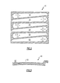
Figure 2 is a sectional view of a BOAS segment; -
Figure 3 is a sectional view of the BOAS segment; -
Figure 4 is an exploded perspective view of the BOAS segment with a plug assembly therefor; -
Figure 5 is an exploded side view of the BOAS segment with a plug assembly therefor; -
Figure 6 is a partial exploded side view of the plug assembly; -
Figure 7 is a side view of the plug assembly in an assembled condition; -
Figure 8 is an exploded side view of another non-limiting embodiment of a plug assembly; -
Figure 9 is an exploded side view of another non-limiting embodiment of a plug assembly; -
Figure 10 is an exploded side view of another non-limiting embodiment of a plug assembly; -
Figure 11 is a side view of the plug assembly ofFigure 10 in an assembled condition. -
Figure 1 schematically illustrates agas turbine engine 20, illustrated partially as a High PressureTurbine HPT section 22 disposed along a common engine longitudinal axis A. Theengine 20 includes a Blade Outer Air Seal (BOAS)assembly 24 to provide an outer core gas path seal for theturbine section 22. It should be understood that although a BOAS assembly for a HPT is disclosed in the illustrated embodiment, the BOAS assembly may be utilized in any section of a gas turbine engine. The BOAS segment may find beneficial use in many industries including aerospace, industrial, electricity generation, naval propulsion, pumping sets for gas and oil transmission, aircraft propulsion, vehicle engines, and stationary power plants. - The
turbine section 22 includes arotor assembly 26 disposed between forward 28 andaft 30 stationary vane assemblies. Outer vane supports 28A, 30A attach the respective vane assemblies to anengine case 32. Therotor assembly 26 includes a plurality ofairfoils 34 circumferentially disposed around adisk 36. The distal end of eachairfoil 34 may be referred to as theblade tip 34T which rides adjacent to theBOAS assembly 24. - The BOAS
assembly 24 is disposed in an annulus radially between theengine case 32 and theblade tips 34T. TheBOAS assembly 24 generally includes a blade outer air seal (BOAS) support 38 and a multiple of blade outer air seal (BOAS)segments 40 mountable thereto (Figures 2 and 3 ). The BOASsupport 38 is mounted within theengine case 32 to define forward andaft flanges BOAS segments 40. Theforward flanges 42 and theaft flanges 44 may be circumferentially segmented to receive theBOAS segments 40 in a circumferentially rotated and locked arrangement as generally understood. It should be understood that various interfaces may alternatively be provided. - Each
BOAS segment 40 includes abody 46 which defines aforward interface 48 and anaft interface 50. Theforward interface 48 and theaft interface 50 respectively engage theflanges individual BOAS segment 40 thereto. - Each
BOAS segment 40 includes one ormore cavities 52 to receive a secondary cooling airflow S. It should be understood that various alternative cavity and passageway arrangements may be provided. Eachcavity 52 may be formed through, for example, an investment casting process. - With reference to
Figure 4 , the investment casting process typically requires one or more core run outopenings 60 be plugged with aplug assembly 62 to assure performance of theBOAS segment 40. It should be understood that although theplug assembly 62 is used to the plug the core run out opening 60 of aBOAS segment 40, theplug assembly 62 may be utilized in various other components. - The core run-out opening 60 generally includes a
bore portion 64 and a boreanti-liberation portion 66. The boreanti-liberation portion 66 in the disclosed non-limiting embodiment, is a reduced diameter portion adjacent to the innermost section of thebore portion 64. In the disclosed, non-limiting embodiment, the boreanti-liberation portion 66 includes a radially inward directed shoulder 68 (also illustrated inFigure 5 ). - The
plug assembly 62 generally includes acup 70 and awedge 72. Thecup 70 is inserted along an axis C of the as-cast core run out opening 60. Thecup 70 includes acup portion 74 and a cupanti-liberation portion 76 at an end section thereof. The cupanti-liberation portion 76 in the disclosed non-limiting embodiment may include a first reduceddiameter portion 78 and a second reduceddiameter portion 80. The first reduceddiameter portion 78 and the second reduceddiameter portion 80 define a diameter smaller than thecup portion 74. The first reduceddiameter portion 78 defines a closed end section of thecup 70 and defines a diameter greater than the second reduceddiameter portion 80. That is, the second reduceddiameter portion 80 is the smallest diameter and is axially located generally in line with the radially inward directedshoulder 68. - With reference to
Figure 6 , once thecup 70 is located into the core run-out opening 60 such that thecup portion 74 abuts the radially inward directedshoulder 68 and the second reduceddiameter portion 80 is axially located generally in line with the radially inward directedshoulder 68, thewedge 72 is pressed into thecup 70. As thewedge 72 is pressed into thecup 70, thewedge 72 expands thecup 70 into a press fit with the bore portion 64 (Figure 7 ). Thewedge 72, when pressed into thecup 70, also expands the first reduceddiameter portion 78 and the second reduceddiameter portion 80 relative to the radially inward directedshoulder 68 such that the first reduceddiameter portion 78 defines a diameter greater than the radially inward directedshoulder 68. Thecup 70 is thereby further locked in place through the interaction of thecup anti-liberation portion 76 and the bore anti-liberationportion 66. - The
wedge 72 may be of various shapes such as a pin shape to provide a flush fit with the core run out opening 60 or a ball shape wedge 72' (Figure 8 ) should a flush fit not be required. Thewedge 72" may additionally include awedge body 82 and aprotrusion 84 which facilities expansion of the first reduceddiameter portion 78 and the second reduced diameter portion 80 (Figure 9 ). Theprotrusion 84 extends from a distal end of thewedge body 82 but may define a lesser diameter than thewedge body 82. Theprotrusion 84 may be of various shapes such as cylindrical, bull nose, round nose, conical, frustro-conical, angular or other shape which facilities expansion of the first reduceddiameter portion 78 and the second reduceddiameter portion 80. - With reference to
Figure 10 , an alternate non-limiting embodiment of the cup 70' includes anaxial slit 86 which extends at least partially along the length of the cup 70'. Theaxial slit 86 facilitates expansion of the first reduceddiameter portion 78 and the second reduceddiameter portion 80 of the cup 70' (Figure 11 ). - The plug assembly provides a consistent robust method which is less reliant on cleaning and surface preparation than brazing. The plug assembly is also less expensive since brazing/welding operation isn't required. Alternatively, brazing may be used as a redundant retention and need not be the primary retaining method. Without brazing, there is no need for heat treat which provides a quicker installation without need of a high proficiency worker. Moreover, the plug assembly may provide materials with higher temperature capability than with metallurgical bond.
- It should be understood that like reference numerals identify corresponding or similar elements throughout the several drawings. It should also be understood that although a particular component arrangement is disclosed in the illustrated embodiment, other arrangements will benefit herefrom.
- Although particular step sequences are shown, described, and claimed, it should be understood that steps may be performed in any order, separated or combined unless otherwise indicated and will still benefit from the present invention.
- The foregoing description is exemplary rather than defined by the limitations within. Many modifications and variations of the present invention are possible in light of the above teachings. The disclosed embodiments of this invention have been disclosed, however, one of ordinary skill in the art would recognize that certain modifications would come within the scope of this invention. It is, therefore, to be understood that within the scope of the appended claims, the invention may be practiced otherwise than as specifically described. For that reason the following claims should be studied to determine the true scope and content of this invention.
Claims (15)
- A plug assembly (62) comprising:a cup (70;70') which defines a cup portion (74) and a cup anti-liberation portion (76) along an axis; anda wedge (72;72';72") mountable within said cup portion (74) to at least partially radially expand said cup anti-liberation portion (76).
- The plug assembly as recited in claim 1, wherein said wedge (72) is a pin.
- The plug assembly as recited in claim 1 or 2, wherein said cup anti-liberation portion includes a first reduced diameter portion (78) and a second reduced diameter portion (80) which each define a diameter smaller than a diameter defined by said cup portion (74).
- The plug assembly as recited in claim 3, wherein said first reduced diameter portion (78) defines a closed end section of said cup (74).
- The plug assembly as recited in claim 3 or 4, wherein said first reduced diameter portion (78) defines a diameter greater than a diameter of said second reduced diameter portion (80).
- The plug assembly as recited in any preceding claim, wherein said cup (70') includes an axial slit (86).
- The plug assembly as recited in any preceding claim, wherein said wedge includes a wedge body (82) and a protrusion (84) that extends from a distal end of said wedge body (82).
- The plug assembly as recited in any preceding claim, wherein said wedge includes a wedge body (82) and a wedge protrusion (84) that extends from a distal end of said wedge body (82), said wedge protrusion (84) defines a lesser diameter than said wedge body (82).
- A component comprising:a bore (60) which defines a bore portion (64) and a bore anti-liberation portion (66) along an axis; anda plug assembly (62) as recited in any preceding claim, whereinsaid wedge is mountable within said cup portion (74) to engage said cup anti-liberation portion (76) with said bore anti-liberation portion (66).
- The component as recited in claim 9, wherein said wedge (72) is a pin, said pin (72) flush with an end of said bore (60).
- The component as recited in claim 9 or 10, wherein said cup anti-liberation portion includes a first reduced diameter portion (78) and a second reduced diameter portion (80), said bore anti-liberation portion (66) defines a radially inward directed shoulder (68), said second reduced diameter portion axially aligned with said radially inward directed shoulder (68).
- The component as recited in claim 9, 10 or 11, wherein said bore (60) is within a Blade Outer Air Seal (BOAS) segment.
- A method of plugging an opening (64) comprising:pressing a wedge (72) into a cup (70) to at least partially radially expand a cup anti-liberation portion (76) and engage the cup anti-liberation portion (76) with a bore anti-liberation portion (66).
- The method as recited in claim 13, further comprising forming a bore with a bore portion (64) and the bore anti-liberation portion (66) along an axis, and optionally further comprising pressing the wedge (72;72';72") and the cup (70;70') flush into the bore portion (64).
- The method as recited in claim 14, further comprising pressing the wedge (72;72';72") into the bore until a wedge body (82) abuts a radially inward directed shoulder (68) and a wedge protrusion (84) axially extends at least partially beyond the radially inward directed shoulder (68).
Applications Claiming Priority (1)
| Application Number | Priority Date | Filing Date | Title |
|---|---|---|---|
| US13/163,929 US20120319360A1 (en) | 2011-06-20 | 2011-06-20 | Plug assembly for blade outer air seal |
Publications (3)
| Publication Number | Publication Date |
|---|---|
| EP2540988A2 true EP2540988A2 (en) | 2013-01-02 |
| EP2540988A3 EP2540988A3 (en) | 2017-03-29 |
| EP2540988B1 EP2540988B1 (en) | 2020-04-29 |
Family
ID=46318969
Family Applications (1)
| Application Number | Title | Priority Date | Filing Date |
|---|---|---|---|
| EP12172156.7A Active EP2540988B1 (en) | 2011-06-20 | 2012-06-15 | Blade outer air seal with a plug assembly and method |
Country Status (2)
| Country | Link |
|---|---|
| US (1) | US20120319360A1 (en) |
| EP (1) | EP2540988B1 (en) |
Families Citing this family (5)
| Publication number | Priority date | Publication date | Assignee | Title |
|---|---|---|---|---|
| DE102016215807A1 (en) * | 2016-08-23 | 2018-03-01 | MTU Aero Engines AG | Inner ring for a vane ring of a turbomachine |
| DE102017109952A1 (en) * | 2017-05-09 | 2018-11-15 | Rolls-Royce Deutschland Ltd & Co Kg | Rotor device of a turbomachine |
| DE102018210601A1 (en) * | 2018-06-28 | 2020-01-02 | MTU Aero Engines AG | SEGMENT RING FOR ASSEMBLY IN A FLOWING MACHINE |
| US10648407B2 (en) * | 2018-09-05 | 2020-05-12 | United Technologies Corporation | CMC boas cooling air flow guide |
| US10634010B2 (en) * | 2018-09-05 | 2020-04-28 | United Technologies Corporation | CMC BOAS axial retaining clip |
Family Cites Families (8)
| Publication number | Priority date | Publication date | Assignee | Title |
|---|---|---|---|---|
| US3691924A (en) * | 1970-05-18 | 1972-09-19 | William H Baker | Expansible drive rivet |
| US4375342A (en) * | 1981-01-14 | 1983-03-01 | Phillips Plastic Corp. | Two-piece plastic fastener |
| US4930459A (en) * | 1989-07-21 | 1990-06-05 | Sdi Operating Partners, L.P. | Freeze plug |
| US6749384B1 (en) * | 1993-02-17 | 2004-06-15 | Southco, Inc. | Drive rivet |
| US7650926B2 (en) * | 2006-09-28 | 2010-01-26 | United Technologies Corporation | Blade outer air seals, cores, and manufacture methods |
| US8122583B2 (en) * | 2007-06-05 | 2012-02-28 | United Technologies Corporation | Method of machining parts having holes |
| GB0721325D0 (en) * | 2007-10-31 | 2007-12-12 | Rolls Royce Plc | fastener arrangements |
| JP5838537B2 (en) * | 2011-03-02 | 2016-01-06 | 学校法人日本大学 | Joining method and structure of plate materials using rivets |
-
2011
- 2011-06-20 US US13/163,929 patent/US20120319360A1/en not_active Abandoned
-
2012
- 2012-06-15 EP EP12172156.7A patent/EP2540988B1/en active Active
Also Published As
| Publication number | Publication date |
|---|---|
| EP2540988A3 (en) | 2017-03-29 |
| EP2540988B1 (en) | 2020-04-29 |
| US20120319360A1 (en) | 2012-12-20 |
Similar Documents
| Publication | Publication Date | Title |
|---|---|---|
| US10301947B2 (en) | Gas turbine engine component cooling circuit | |
| EP3068975B1 (en) | Gas turbine engine component and corresponding methods of manufacturing | |
| EP3124743B1 (en) | Nozzle guide vane and method for forming a nozzle guide vane | |
| EP2900961B1 (en) | Gas turbine engine airfoil cooling circuit | |
| US9080458B2 (en) | Blade outer air seal with multi impingement plate assembly | |
| US9765630B2 (en) | Interior cooling circuits in turbine blades | |
| US10920601B2 (en) | Blade outer air seal fin cooling assembly and method | |
| EP2369139A2 (en) | Nozzle segment with reduced weight flange | |
| US10415403B2 (en) | Cooled blisk for gas turbine engine | |
| EP2484867B1 (en) | Rotating component of a turbine engine | |
| EP3172410B1 (en) | Stator vane system usable within a gas turbine engine | |
| US20170211415A1 (en) | Variable thickness core for gas turbine engine component | |
| EP2540988B1 (en) | Blade outer air seal with a plug assembly and method | |
| US20180209277A1 (en) | Investment casting core | |
| JP2004286016A (en) | Method and apparatus for assembling a turbine engine | |
| EP3379032B1 (en) | Cooled airfoil and corresponding gas turbine engine | |
| EP2551468A1 (en) | Blade outer air seal assembly with passage joined cavities and corresponding operating method | |
| EP3674517A1 (en) | Kinetic disassembly of support structure system for additively manufactured rotating components | |
| EP3415716B1 (en) | Blade tip cooling | |
| US11236625B2 (en) | Method of making a cooled airfoil assembly for a turbine engine |
Legal Events
| Date | Code | Title | Description |
|---|---|---|---|
| PUAI | Public reference made under article 153(3) epc to a published international application that has entered the european phase |
Free format text: ORIGINAL CODE: 0009012 |
|
| AK | Designated contracting states |
Kind code of ref document: A2 Designated state(s): AL AT BE BG CH CY CZ DE DK EE ES FI FR GB GR HR HU IE IS IT LI LT LU LV MC MK MT NL NO PL PT RO RS SE SI SK SM TR |
|
| AX | Request for extension of the european patent |
Extension state: BA ME |
|
| RAP1 | Party data changed (applicant data changed or rights of an application transferred) |
Owner name: UNITED TECHNOLOGIES CORPORATION |
|
| PUAL | Search report despatched |
Free format text: ORIGINAL CODE: 0009013 |
|
| AK | Designated contracting states |
Kind code of ref document: A3 Designated state(s): AL AT BE BG CH CY CZ DE DK EE ES FI FR GB GR HR HU IE IS IT LI LT LU LV MC MK MT NL NO PL PT RO RS SE SI SK SM TR |
|
| AX | Request for extension of the european patent |
Extension state: BA ME |
|
| RIC1 | Information provided on ipc code assigned before grant |
Ipc: F01D 11/08 20060101AFI20170223BHEP |
|
| STAA | Information on the status of an ep patent application or granted ep patent |
Free format text: STATUS: REQUEST FOR EXAMINATION WAS MADE |
|
| 17P | Request for examination filed |
Effective date: 20170926 |
|
| RBV | Designated contracting states (corrected) |
Designated state(s): AL AT BE BG CH CY CZ DE DK EE ES FI FR GB GR HR HU IE IS IT LI LT LU LV MC MK MT NL NO PL PT RO RS SE SI SK SM TR |
|
| STAA | Information on the status of an ep patent application or granted ep patent |
Free format text: STATUS: EXAMINATION IS IN PROGRESS |
|
| 17Q | First examination report despatched |
Effective date: 20190508 |
|
| GRAP | Despatch of communication of intention to grant a patent |
Free format text: ORIGINAL CODE: EPIDOSNIGR1 |
|
| STAA | Information on the status of an ep patent application or granted ep patent |
Free format text: STATUS: GRANT OF PATENT IS INTENDED |
|
| INTG | Intention to grant announced |
Effective date: 20191112 |
|
| GRAS | Grant fee paid |
Free format text: ORIGINAL CODE: EPIDOSNIGR3 |
|
| GRAA | (expected) grant |
Free format text: ORIGINAL CODE: 0009210 |
|
| STAA | Information on the status of an ep patent application or granted ep patent |
Free format text: STATUS: THE PATENT HAS BEEN GRANTED |
|
| AK | Designated contracting states |
Kind code of ref document: B1 Designated state(s): AL AT BE BG CH CY CZ DE DK EE ES FI FR GB GR HR HU IE IS IT LI LT LU LV MC MK MT NL NO PL PT RO RS SE SI SK SM TR |
|
| REG | Reference to a national code |
Ref country code: GB Ref legal event code: FG4D |
|
| REG | Reference to a national code |
Ref country code: CH Ref legal event code: EP |
|
| REG | Reference to a national code |
Ref country code: AT Ref legal event code: REF Ref document number: 1263626 Country of ref document: AT Kind code of ref document: T Effective date: 20200515 |
|
| REG | Reference to a national code |
Ref country code: DE Ref legal event code: R096 Ref document number: 602012069627 Country of ref document: DE |
|
| REG | Reference to a national code |
Ref country code: IE Ref legal event code: FG4D |
|
| REG | Reference to a national code |
Ref country code: NL Ref legal event code: MP Effective date: 20200429 |
|
| REG | Reference to a national code |
Ref country code: LT Ref legal event code: MG4D |
|
| PG25 | Lapsed in a contracting state [announced via postgrant information from national office to epo] |
Ref country code: IS Free format text: LAPSE BECAUSE OF FAILURE TO SUBMIT A TRANSLATION OF THE DESCRIPTION OR TO PAY THE FEE WITHIN THE PRESCRIBED TIME-LIMIT Effective date: 20200829 Ref country code: FI Free format text: LAPSE BECAUSE OF FAILURE TO SUBMIT A TRANSLATION OF THE DESCRIPTION OR TO PAY THE FEE WITHIN THE PRESCRIBED TIME-LIMIT Effective date: 20200429 Ref country code: GR Free format text: LAPSE BECAUSE OF FAILURE TO SUBMIT A TRANSLATION OF THE DESCRIPTION OR TO PAY THE FEE WITHIN THE PRESCRIBED TIME-LIMIT Effective date: 20200730 Ref country code: SE Free format text: LAPSE BECAUSE OF FAILURE TO SUBMIT A TRANSLATION OF THE DESCRIPTION OR TO PAY THE FEE WITHIN THE PRESCRIBED TIME-LIMIT Effective date: 20200429 Ref country code: LT Free format text: LAPSE BECAUSE OF FAILURE TO SUBMIT A TRANSLATION OF THE DESCRIPTION OR TO PAY THE FEE WITHIN THE PRESCRIBED TIME-LIMIT Effective date: 20200429 Ref country code: PT Free format text: LAPSE BECAUSE OF FAILURE TO SUBMIT A TRANSLATION OF THE DESCRIPTION OR TO PAY THE FEE WITHIN THE PRESCRIBED TIME-LIMIT Effective date: 20200831 Ref country code: NO Free format text: LAPSE BECAUSE OF FAILURE TO SUBMIT A TRANSLATION OF THE DESCRIPTION OR TO PAY THE FEE WITHIN THE PRESCRIBED TIME-LIMIT Effective date: 20200729 |
|
| REG | Reference to a national code |
Ref country code: AT Ref legal event code: MK05 Ref document number: 1263626 Country of ref document: AT Kind code of ref document: T Effective date: 20200429 |
|
| PG25 | Lapsed in a contracting state [announced via postgrant information from national office to epo] |
Ref country code: BG Free format text: LAPSE BECAUSE OF FAILURE TO SUBMIT A TRANSLATION OF THE DESCRIPTION OR TO PAY THE FEE WITHIN THE PRESCRIBED TIME-LIMIT Effective date: 20200729 Ref country code: RS Free format text: LAPSE BECAUSE OF FAILURE TO SUBMIT A TRANSLATION OF THE DESCRIPTION OR TO PAY THE FEE WITHIN THE PRESCRIBED TIME-LIMIT Effective date: 20200429 Ref country code: HR Free format text: LAPSE BECAUSE OF FAILURE TO SUBMIT A TRANSLATION OF THE DESCRIPTION OR TO PAY THE FEE WITHIN THE PRESCRIBED TIME-LIMIT Effective date: 20200429 Ref country code: LV Free format text: LAPSE BECAUSE OF FAILURE TO SUBMIT A TRANSLATION OF THE DESCRIPTION OR TO PAY THE FEE WITHIN THE PRESCRIBED TIME-LIMIT Effective date: 20200429 |
|
| PG25 | Lapsed in a contracting state [announced via postgrant information from national office to epo] |
Ref country code: AL Free format text: LAPSE BECAUSE OF FAILURE TO SUBMIT A TRANSLATION OF THE DESCRIPTION OR TO PAY THE FEE WITHIN THE PRESCRIBED TIME-LIMIT Effective date: 20200429 Ref country code: NL Free format text: LAPSE BECAUSE OF FAILURE TO SUBMIT A TRANSLATION OF THE DESCRIPTION OR TO PAY THE FEE WITHIN THE PRESCRIBED TIME-LIMIT Effective date: 20200429 |
|
| PG25 | Lapsed in a contracting state [announced via postgrant information from national office to epo] |
Ref country code: AT Free format text: LAPSE BECAUSE OF FAILURE TO SUBMIT A TRANSLATION OF THE DESCRIPTION OR TO PAY THE FEE WITHIN THE PRESCRIBED TIME-LIMIT Effective date: 20200429 Ref country code: ES Free format text: LAPSE BECAUSE OF FAILURE TO SUBMIT A TRANSLATION OF THE DESCRIPTION OR TO PAY THE FEE WITHIN THE PRESCRIBED TIME-LIMIT Effective date: 20200429 Ref country code: DK Free format text: LAPSE BECAUSE OF FAILURE TO SUBMIT A TRANSLATION OF THE DESCRIPTION OR TO PAY THE FEE WITHIN THE PRESCRIBED TIME-LIMIT Effective date: 20200429 Ref country code: SM Free format text: LAPSE BECAUSE OF FAILURE TO SUBMIT A TRANSLATION OF THE DESCRIPTION OR TO PAY THE FEE WITHIN THE PRESCRIBED TIME-LIMIT Effective date: 20200429 Ref country code: EE Free format text: LAPSE BECAUSE OF FAILURE TO SUBMIT A TRANSLATION OF THE DESCRIPTION OR TO PAY THE FEE WITHIN THE PRESCRIBED TIME-LIMIT Effective date: 20200429 Ref country code: IT Free format text: LAPSE BECAUSE OF FAILURE TO SUBMIT A TRANSLATION OF THE DESCRIPTION OR TO PAY THE FEE WITHIN THE PRESCRIBED TIME-LIMIT Effective date: 20200429 Ref country code: RO Free format text: LAPSE BECAUSE OF FAILURE TO SUBMIT A TRANSLATION OF THE DESCRIPTION OR TO PAY THE FEE WITHIN THE PRESCRIBED TIME-LIMIT Effective date: 20200429 Ref country code: CZ Free format text: LAPSE BECAUSE OF FAILURE TO SUBMIT A TRANSLATION OF THE DESCRIPTION OR TO PAY THE FEE WITHIN THE PRESCRIBED TIME-LIMIT Effective date: 20200429 Ref country code: MC Free format text: LAPSE BECAUSE OF FAILURE TO SUBMIT A TRANSLATION OF THE DESCRIPTION OR TO PAY THE FEE WITHIN THE PRESCRIBED TIME-LIMIT Effective date: 20200429 |
|
| REG | Reference to a national code |
Ref country code: CH Ref legal event code: PL |
|
| REG | Reference to a national code |
Ref country code: DE Ref legal event code: R097 Ref document number: 602012069627 Country of ref document: DE |
|
| PG25 | Lapsed in a contracting state [announced via postgrant information from national office to epo] |
Ref country code: SK Free format text: LAPSE BECAUSE OF FAILURE TO SUBMIT A TRANSLATION OF THE DESCRIPTION OR TO PAY THE FEE WITHIN THE PRESCRIBED TIME-LIMIT Effective date: 20200429 Ref country code: PL Free format text: LAPSE BECAUSE OF FAILURE TO SUBMIT A TRANSLATION OF THE DESCRIPTION OR TO PAY THE FEE WITHIN THE PRESCRIBED TIME-LIMIT Effective date: 20200429 |
|
| PLBE | No opposition filed within time limit |
Free format text: ORIGINAL CODE: 0009261 |
|
| STAA | Information on the status of an ep patent application or granted ep patent |
Free format text: STATUS: NO OPPOSITION FILED WITHIN TIME LIMIT |
|
| RAP2 | Party data changed (patent owner data changed or rights of a patent transferred) |
Owner name: RAYTHEON TECHNOLOGIES CORPORATION |
|
| PG25 | Lapsed in a contracting state [announced via postgrant information from national office to epo] |
Ref country code: LU Free format text: LAPSE BECAUSE OF NON-PAYMENT OF DUE FEES Effective date: 20200615 |
|
| 26N | No opposition filed |
Effective date: 20210201 |
|
| REG | Reference to a national code |
Ref country code: BE Ref legal event code: MM Effective date: 20200630 |
|
| PG25 | Lapsed in a contracting state [announced via postgrant information from national office to epo] |
Ref country code: IE Free format text: LAPSE BECAUSE OF NON-PAYMENT OF DUE FEES Effective date: 20200615 Ref country code: LI Free format text: LAPSE BECAUSE OF NON-PAYMENT OF DUE FEES Effective date: 20200630 Ref country code: CH Free format text: LAPSE BECAUSE OF NON-PAYMENT OF DUE FEES Effective date: 20200630 |
|
| PG25 | Lapsed in a contracting state [announced via postgrant information from national office to epo] |
Ref country code: BE Free format text: LAPSE BECAUSE OF NON-PAYMENT OF DUE FEES Effective date: 20200630 Ref country code: SI Free format text: LAPSE BECAUSE OF FAILURE TO SUBMIT A TRANSLATION OF THE DESCRIPTION OR TO PAY THE FEE WITHIN THE PRESCRIBED TIME-LIMIT Effective date: 20200429 |
|
| PG25 | Lapsed in a contracting state [announced via postgrant information from national office to epo] |
Ref country code: TR Free format text: LAPSE BECAUSE OF FAILURE TO SUBMIT A TRANSLATION OF THE DESCRIPTION OR TO PAY THE FEE WITHIN THE PRESCRIBED TIME-LIMIT Effective date: 20200429 Ref country code: MT Free format text: LAPSE BECAUSE OF FAILURE TO SUBMIT A TRANSLATION OF THE DESCRIPTION OR TO PAY THE FEE WITHIN THE PRESCRIBED TIME-LIMIT Effective date: 20200429 Ref country code: CY Free format text: LAPSE BECAUSE OF FAILURE TO SUBMIT A TRANSLATION OF THE DESCRIPTION OR TO PAY THE FEE WITHIN THE PRESCRIBED TIME-LIMIT Effective date: 20200429 |
|
| PG25 | Lapsed in a contracting state [announced via postgrant information from national office to epo] |
Ref country code: MK Free format text: LAPSE BECAUSE OF FAILURE TO SUBMIT A TRANSLATION OF THE DESCRIPTION OR TO PAY THE FEE WITHIN THE PRESCRIBED TIME-LIMIT Effective date: 20200429 |
|
| REG | Reference to a national code |
Ref country code: DE Ref legal event code: R081 Ref document number: 602012069627 Country of ref document: DE Owner name: RAYTHEON TECHNOLOGIES CORPORATION (N.D.GES.D.S, US Free format text: FORMER OWNER: UNITED TECHNOLOGIES CORPORATION, FARMINGTON, CONN., US |
|
| P01 | Opt-out of the competence of the unified patent court (upc) registered |
Effective date: 20230520 |
|
| PGFP | Annual fee paid to national office [announced via postgrant information from national office to epo] |
Ref country code: GB Payment date: 20240521 Year of fee payment: 13 |
|
| PGFP | Annual fee paid to national office [announced via postgrant information from national office to epo] |
Ref country code: DE Payment date: 20240521 Year of fee payment: 13 |
|
| PGFP | Annual fee paid to national office [announced via postgrant information from national office to epo] |
Ref country code: FR Payment date: 20240522 Year of fee payment: 13 |
|
| REG | Reference to a national code |
Ref country code: DE Ref legal event code: R119 Ref document number: 602012069627 Country of ref document: DE |
|
| GBPC | Gb: european patent ceased through non-payment of renewal fee |
Effective date: 20250615 |
|
| PG25 | Lapsed in a contracting state [announced via postgrant information from national office to epo] |
Ref country code: GB Free format text: LAPSE BECAUSE OF NON-PAYMENT OF DUE FEES Effective date: 20250615 |
|
| PG25 | Lapsed in a contracting state [announced via postgrant information from national office to epo] |
Ref country code: DE Free format text: LAPSE BECAUSE OF NON-PAYMENT OF DUE FEES Effective date: 20260101 |
|
| PG25 | Lapsed in a contracting state [announced via postgrant information from national office to epo] |
Ref country code: FR Free format text: LAPSE BECAUSE OF NON-PAYMENT OF DUE FEES Effective date: 20250630 |