EP2540986A2 - Turbine blade - Google Patents
Turbine blade Download PDFInfo
- Publication number
- EP2540986A2 EP2540986A2 EP12174450A EP12174450A EP2540986A2 EP 2540986 A2 EP2540986 A2 EP 2540986A2 EP 12174450 A EP12174450 A EP 12174450A EP 12174450 A EP12174450 A EP 12174450A EP 2540986 A2 EP2540986 A2 EP 2540986A2
- Authority
- EP
- European Patent Office
- Prior art keywords
- section
- blade
- sealing
- sealing plate
- front wall
- Prior art date
- Legal status (The legal status is an assumption and is not a legal conclusion. Google has not performed a legal analysis and makes no representation as to the accuracy of the status listed.)
- Withdrawn
Links
Images

Classifications
-
- F—MECHANICAL ENGINEERING; LIGHTING; HEATING; WEAPONS; BLASTING
- F01—MACHINES OR ENGINES IN GENERAL; ENGINE PLANTS IN GENERAL; STEAM ENGINES
- F01D—NON-POSITIVE DISPLACEMENT MACHINES OR ENGINES, e.g. STEAM TURBINES
- F01D11/00—Preventing or minimising internal leakage of working-fluid, e.g. between stages
- F01D11/02—Preventing or minimising internal leakage of working-fluid, e.g. between stages by non-contact sealings, e.g. of labyrinth type
-
- F—MECHANICAL ENGINEERING; LIGHTING; HEATING; WEAPONS; BLASTING
- F01—MACHINES OR ENGINES IN GENERAL; ENGINE PLANTS IN GENERAL; STEAM ENGINES
- F01D—NON-POSITIVE DISPLACEMENT MACHINES OR ENGINES, e.g. STEAM TURBINES
- F01D11/00—Preventing or minimising internal leakage of working-fluid, e.g. between stages
- F01D11/001—Preventing or minimising internal leakage of working-fluid, e.g. between stages for sealing space between stator blade and rotor
-
- F—MECHANICAL ENGINEERING; LIGHTING; HEATING; WEAPONS; BLASTING
- F01—MACHINES OR ENGINES IN GENERAL; ENGINE PLANTS IN GENERAL; STEAM ENGINES
- F01D—NON-POSITIVE DISPLACEMENT MACHINES OR ENGINES, e.g. STEAM TURBINES
- F01D11/00—Preventing or minimising internal leakage of working-fluid, e.g. between stages
- F01D11/005—Sealing means between non relatively rotating elements
- F01D11/006—Sealing the gap between rotor blades or blades and rotor
- F01D11/008—Sealing the gap between rotor blades or blades and rotor by spacer elements between the blades, e.g. independent interblade platforms
-
- F—MECHANICAL ENGINEERING; LIGHTING; HEATING; WEAPONS; BLASTING
- F05—INDEXING SCHEMES RELATING TO ENGINES OR PUMPS IN VARIOUS SUBCLASSES OF CLASSES F01-F04
- F05D—INDEXING SCHEME FOR ASPECTS RELATING TO NON-POSITIVE-DISPLACEMENT MACHINES OR ENGINES, GAS-TURBINES OR JET-PROPULSION PLANTS
- F05D2240/00—Components
- F05D2240/80—Platforms for stationary or moving blades
Definitions
- the present invention relates to a blade, in particular to a cooled blade, for a turbine as well as to a rotor for a turbine with at least one such blade.
- a turbine in particular a gas turbine, usually comprises a rotor and a stator with the rotor comprising rotating blades arranged radially around a shaft.
- the blade itself comprises a platform, wherein a top plate of the platform supports an airfoil of the blade at the inner end of the airfoil. At its opposite end, i.e. at a bottom plate, the platform is adapted for the connection to the shaft.
- the rotation of the blades leads to a rotation of the shaft, wherein this rotation is used for further purposes such as the generation of electricity.
- the expansion energy of a fluid is used.
- the expanding fluid thereby flows past the blades along a flow direction, wherein stationary vanes of the stator provide a beneficial flow path for the driving fluid.
- adjacent blades are arranged in the circumferential direction with respect to the rotation of the rotor, wherein the blades are arranged adjacent to vanes in the flow direction. That is, in particular, the blades face a neighbouring vane in the upstream direction, with respect to the flow direction, of the driving fluid.
- the platform of a said blade comprises a curved front wall facing an upstream neighbouring vane.
- the front wall further supports a sealing section for providing sealing between said blade and the upstream neighbouring vane, said sealing section being at least partially arranged below the neighbouring vane, wherein below is defined with respect to a radial direction of the shaft.
- the sealing section is thus at least partially arranged below the vane in particular at an inner end of the vane.
- a flow path width reduction is known as a reasonable method to increase the efficiency of a turbine of the said kind, in particular during a retrofit. That is, the path of the driving fluid is restricted in a direction crossing the flow path direction, in particular in the radial direction, which increases the speed of the driving fluid along the flow path and thus the efficiency of the turbine.
- the blades and vanes accordingly and preserve other parts of the turbine such as the shaft.
- Such an adaptation of a blade comprises in particular an increase of the platform size. That is the size of the platform is increased along the radial direction with respect to the shaft. This increase leads to a corresponding increase in the size of a platform of the corresponding vane. Keeping the remaining main parts of the turbine, in particular the shaft, as they are leads to a demand for an aligned and improved sealing between the blade and the neighbouring vane.
- the present invention addresses the problem of delivering an improved or at least alternative embodiment for a blade of the said kind, which in particular is characterised by an improved sealing property.
- the present invention is based on the general idea of ensuring a proper sealing between a blade and an upstream neighbouring vane of a turbine by providing a front wall of a platform of the blade with a flat section which runs perpendicular to a top plate of the platform carrying an airfoil of the blade at the inner end of the blade, said front wall facing the upstream neighbouring vane and comprising a curved section supporting a sealing section.
- the sealing section provides sealing between the blade and the upstream neighbouring vane and is at least partially arranged below said vane.
- the given directions, such as top or below are thereby defined with respect to a radial direction of an associated shaft to which the blade is connected.
- the top plate of the platform is that plate of the platform being further away from the shaft and in particular running parallel to the shaft. Accordingly, a sealing section arranged below the vane is provided by an arrangement whereby the sealing section is closer to the shaft than the vane. Similarly, the inner end of the airfoil is the end of the airfoil closer to the shaft and/or facing the shaft.
- the invention is thus based on the idea that the minimum distance between the blade and the upstream neighbouring vane required to accommodate the sealing section below said vane is reduced by providing the front wall with the flat section.
- This is in particular beneficial if the height of the platform is increased and the distance between the blade and the upstream neighbouring vane is kept, wherein the height is given with respect to the radial direction and thus as seen in a longitudinal section view of the blade.
- Such a height increase of the platform is in particular used during a retrofit process of the turbine, wherein the vane is adapted accordingly to decrease a flow path width and thus the available radial volume leading to an efficiency increase of the turbine by a rise of the speed of a driving fluid of the turbine.
- the front wall of the platform of the blade comprises a flat section wherein the flat section is arranged between the top plate of the platform and the curved section of the front wall.
- the curved section is arranged below the flat section and the flat section is arranged below the top plate, wherein below is given with respect to the radial direction.
- a transition between the perpendicularly arranged top plate and the flat section is provided by means of an upper transition section arranged between the top plate and the flat section.
- the upper transition section thereby preferably comprises a curved shape to avoid a sharp transition or edge between the top plate and the front wall. That is, the upper transition section is in particular curved with a radius of curvature R3, wherein the direction of curvature is preferably oriented away from the platform.
- a curvature of the upper transition section and the corresponding choice of the radius of curvature R3 moreover lead to desired aerodynamic properties of the blade.
- a respective transition between the flat section and the curved section supporting the sealing section can be realised by means of a lower transition section arranged between the flat section and the curved section, according to a further embodiment.
- the lower transition thereby comprises in particular a radius of curvature R4, which is different from a radius of curvature R5 of the curved section.
- the lower curved section moreover comprises a direction of curvature oriented opposite to the direction of curvature of the upper transition section. That is, in a preferred embodiment, the upper transition section is curved away from the platform while the lower transition section comprises a curvature oriented towards the platform.
- Such an embodiment in particular leads to a sealing section being arranged essentially parallel to the top plate.
- the airfoil of the blade contacts the upper transition section by means of an airfoil transition section.
- the airfoil transition section is thus arranged on the upstream side and at the inner end of the airfoil.
- the airfoil transition section further preferably comprises a complimentary shape, which allows for a smooth transition between the airfoil and the airfoil transition section on its upper side facing the airfoil.
- the airfoil transition section On its lower side opposing the airfoil, the airfoil transition section comprises preferably two different radii of curvature, wherein one of these radii R1 is arranged at one edge of the said side contacting the upper transition section and the other radius R2 is arranged at the opposing edge crossing the upper transition section.
- Said lower side of the airfoil transition section thereby preferably comprises a smooth transition between the two radii of curvature along a path between both said edges.
- the airfoil transition section and the upper transition section are shaped complementarily on their contacting sides, which in particular allows for a smooth transition between the airfoil transition section and the upper transition section and thus for a smooth transition between the airfoil, the front wall and the top plate, in particular for aerodynamic reasons.
- the sealing section supported by the curved section of the front wall comprises at least one fin.
- the fin is thereby arranged on the side of the sealing section facing the airfoil and is arranged below the associated upstream neighbouring vane of the blade.
- the fin therefore projects in the radial direction and is adapted to cooperate with a neighbouring fin to establish a fluidic sealing between the blade and said vane, in particular to prevent the driving fluid of the turbine from accessing the area under the platforms.
- the fin usually cooperates with a facing part of the vane, wherein the cooperating facing part is in particular formed and/or constructed to form a labyrinth seal with the fin.
- Preferred embodiments thereby comprise several fins, adapted to cooperate with a complementary vane part to form the sealing.
- the sealing section comprises at least one fin, which is inclined away from the flat section of the blade. That is, said fin is inclined away from the platform and inclined towards the upstream neighbouring vane and thus against the flow direction.
- said fin is inclined away from the platform and inclined towards the upstream neighbouring vane and thus against the flow direction.
- Such an incline in particular leads to an improved sealing effect of the sealing section when interacting with the according part of the vane.
- at least one fin is inclined towards the flat section of the front wall and thus towards the platform and away from said vane.
- Embodiments comprising a combination of inclined and non inclined as well as different degrees of inclination are also possible and thus form part of the present invention.
- the blade comprises several fins arranged on the sealing section, wherein different fins comprise different sizes and/or shapes. That is one or several fins comprise a different size and/or shape compared to one or more other fins.
- the sealing section comprises four fins facing the airfoil. All four fins further comprise the same inclination away from the platform of the vane and thus against the flow direction. The first three neighbouring fins of the platform moreover have the same size and shape and the fourth fin, i.e. the fin furthest from the platform, comprises a different shape than the other three and is in particular larger than the others.
- the first three fins show the same size and shape while the fourth and thus last fin has a different shape and a larger size.
- the fourth and thus last and bigger fin thereby preferably forms the edge of the sealing section and thus the edge of the front wall. Therefore, in particular in a longitudinal section view of the blade, the first three fins comprise a height H2 and the forth fin comprises another height H3, wherein H3 is bigger than H2.
- the blade can be equipped with sealing plates. Therefore the blade comprises at least one sealing plate guide for the assembly of at least one sealing plate.
- the sealing plate guide therefore forms a recess in which the corresponding sealing plate is arranged in order to establish a seal.
- the sealing plate guide does thereby not necessarily comprise a continuing shape. That is, the sealing plate guide can be constructed in sections along a path, in particular by means of segments.
- a fixing of the sealing plate is further preferably realised by means of fixing portions of the sealing plate guide, wherein said fixing portion is adapted to cooperate with a complementarily shaped fixing part of the corresponding sealing plate. That is, the sealing plate guide in particular comprises at least one fixing portion adapted to interact or receive or engage with the according fixing part of the sealing plate.
- At least one of the sealing plate guides is constructed curvilinear for the assembly of a complementarily shaped sealing plate.
- a sealing plate guide is in particular arranged below the front wall of the blade.
- said sealing plate guide is further running below the whole front wall extending into the sealing section. That is in particular, said sealing plate guide runs below the sealing section and continues below the flat section and the upper transition section. Said sealing plate guide is thereby preferably arranged below one of the circumferential edges of the front wall. Such an arrangement in particular simplifies the assembly of the corresponding sealing plate.
- At least one of the sealing plate guides is arranged below the top plate of the platform.
- Said sealing plate guide is thus in particular arranged parallel to the top plate and can optionally extend over the whole extent of the top plate.
- Said sealing plate guide is thereby preferably arranged below one of the circumferential edges of the top plate.
- the sealing plate guide arranged below the front wall contacts the sealing plate guide arranged below the top plate.
- the contact is thereby in particular realised by a contact of an edge of the sealing plate guide below the front wall with the lower side of the sealing plate guide below the top plate, i.e. with the side of the sealing plate guide opposing the top plate.
- the contact can further be arranged at a position spaced from an edge of the sealing plate guide below the top plate, said edge in particular facing the front wall.
- the blade comprises at least one sealing plate guide arranged at a back wall of the platform for the assembly of a sealing plate, wherein said back wall is opposed to the front wall, i.e. in particular the back wall is arranged on a downstream side of the blade.
- Said sealing plate guide can further be adapted to be aligned with the sealing plate guide at the back wall of a circumferential neighbouring blade. That is the sealing plate guide arranged at the back wall in particular runs across the back wall and in particular over the whole back wall, and can be aligned with a similar sealing plate guide of a neighbouring blade, wherein the same sealing plate is preferably arranged within both said sealing plate guides.
- the said sealing plate guides thereby do not necessarily contact each other.
- the back wall of the blade comprises a projection, wherein the projection is adapted to be arranged in a complementarily shaped recess of the back wall of a circumferential neighbouring blade.
- the blade comprises a recess, wherein the recess is adapted to receive a complementarily shaped projection of the back wall of a circumferential neighbouring blade. The according projections and recesses are thereby conveniently arranged at facing edge of the corresponding back walls.
- the blade can further comprise an arbitrary combination of said recesses and projections cooperating with according recesses and projection of the back wall of the circumferential neighbouring blades.
- a preferred embodiment is however given by a back wall comprising a projection at one of its edges facing the back wall of a circumferential neighbouring blade and a recess at its other edge facing the back wall of the other circumferential neighbouring blade.
- the blade In a longitudinal section view of the blade, i.e. in a section view running along the radial direction, the blade comprises a height of the front wall H, which is defined as the height difference between the top plate and the sealing section of the blade.
- Another characteristic value of the front wall is given by the flat section height H1 in the said longitudinal section view, wherein the flat section height H1 is defined as the height difference between the top plate and the junction between the flat section and the lower transition section.
- a rotor in particular a rotor for a turbine, is equipped with at least one blade according to the invention.
- a rotor preferably comprises several blades according to the invention, said blades arranged adjacently in the circumferential direction.
- the rotor can additionally comprise at least one sealing plate being arranged in the respective sealing plate guide of at least one blade, wherein said sealing plate can comprise a bilayer construction and is additionally or alternatively resilient.
- said rotor is conveniently arranged within a turbine, wherein the front walls of the blades face an upstream neighbouring vane of a stator of the turbine.
- the turbine is also part of the invention.
- a blade 1 comprises a platform 2, wherein the platform 2 comprises a top plate 3 carrying an airfoil 4 at the inner end of the airfoil 4.
- the inner end is in relation to a direction depicted by an arrow 5, wherein the arrow 5 denotes the radial direction of a shaft the blade is connected with, when assembled in a rotor 6 and in a turbine 7 respectively.
- the arrow 5 therefore denotes the radial direction with respect to the rotation of the blade 1.
- the platform 2 of the blade 1 further comprises side walls 8 with respect to a circumferential direction depicted by the arrow 9, wherein said side walls 8 form a platform cavity being enclosed by a front wall 10 and a back wall 11 of the platform 2 with respect to a flow direction depicted by the arrow 12.
- the circumferential direction thereby refers to a direction of rotation of the blade 1, when assembled in the rotor 6 or the turbine 7 respectively.
- a driving fluid flow passes the blade 1 of the turbine 7, said driving fluid flow direction defining the flow direction depicted by the arrow 12.
- the front wall 10 is arranged on an upstream side of the blade 1 with respect to the flow direction given by the arrow 12, which is on the right side of the view shown in Fig. 1 .
- the back wall is respectively arranged on a downstream side, which is the left side of the view shown Fig. 1 .
- the blade 1 moreover comprises a fir tree form 13 arranged on a bottom plate 14 of the platform 2, wherein the term 'bottom' is given with respect to the radial direction given by the arrow 5.
- the fir tree form 13 in particular is shaped to form a connection between the blade 1 and the shaft of the rotor 6 and the turbine 7.
- the airfoil 4 comprises channels 15 of a channel system for cooling purposes.
- the front wall 10 comprises a curved section 16 supporting a sealing section 17 of the front wall 10.
- the curved section 16 is constructed with a radius of curvature R5 and connected to the sealing section 17 on its upstream side, wherein the radius of curvature of the curved section 16 extends generally towards the platform 2.
- the sealing section 17 comprises a planar top side 18, wherein the top side 18 is facing the airfoil 4.
- the top side 18 of the sealing section 17 thus faces in the direction of the arrow 5 and thus in the radial direction and runs parallel to the top plate 3 of the platform 2.
- the sealing section 17 further comprises four fins 19, 20 arranged on its top side 18.
- the first three fins 19 have the same size and shape, wherein the numbering of the fins 19, 20 is done following a direction opposing the flow direction 12 and thus from left to right in the shown view.
- the fourth fin 20 of the sealing section 17 is arranged at the furthermost upstream edge of the sealing section 17 and thus on the furthest right side of the sealing section 17 in the shown view.
- the fin 20 therefore forms the tail of the sealing section 17 on the upstream side and is formed larger than the other fins 19. All four fins 19, 20 are inclined away from the platform 2 and thus towards a direction opposing the flow direction depicted by the arrow 12.
- the first three fins 19 comprise inclined and planar walls 21 which extend from the top side 18 of the sealing section 17 and each fin 19 comprises a planar surface 22 at its distal, wherein the planar surfaces 22 run parallel to the top side 18 of the sealing section 17.
- the fourth fin 20 comprises two walls 23, 24, wherein one of the said walls 23 facing the platform 2 has a curved shape whereas the other wall 24 facing away from the platform 2 has a planar surface.
- the transition between the top side 18 of the sealing section 17 and the fin 20 on the side facing the platform 2 thus comprises a curved shape while all other transitional regions between the top side 18 and the fins 19, 20 are angular.
- the walls 23, 24 of the fin 20 extend to a planar surface 22 at a distal end of said fin 20, wherein said planar surface 22 runs parallel to the top side 18 of the sealing section 17 and thus the top plate 3 of the platform 2.
- the curved section 16 is adjacent a lower transition section 25 on the side of the curved section 16 opposite to the sealing section 17.
- the lower transition section 25 comprises a curved shape having the same direction of curvature as the curved section, i.e. towards the platform, but having a different radius of curvature R4.
- the curved section 16 is thus arranged between the sealing section 17 and the lower transition section 25.
- the lower transition section 25 thereby serves as a transition between the curved section 16 and a flat section 26 of the front wall 10.
- the flat section 26 is thus arranged on the side of the lower transition section 25 opposite to the curved section 16.
- the flat section 26 thereby runs perpendicular to the top plate 3 of the platform 2 and thus also perpendicular to the top side 18 of the sealing section 17.
- An upper transition section 27 is arranged on the side of the flat section 26 opposing the lower transition section 25.
- the upper transition section 27 comprises a curved shape, wherein the curvature is projected away from the platform 2 and thus in the opposite direction to the curvatures of the curved section 16 and the lower transition section 25.
- the upper transition section 27 moreover comprises a radius of curvature R3 and serves as a transition between the perpendicularly arranged top plate 3 and flat section 26.
- a height H of the front wall 10 is defined by a distance along the radial direction 5 between the top plate 3 and the top side 18 of the of the sealing section 17, these being arranged in a parallel manner.
- the curved section 16, the lower transition section 25, the flat section 26 and the upper transition section 27 all have a rectangular shape and the long sides of the respective sections 16, 25, 26, 27 form the boarders between adjacent sections.
- the rectangular shape of the upper transition section 27 is however overlapped by a curved tip 28 of an airfoil transition section 29, as shown in Fig. 2 , wherein the airfoil transition section 29 serves as a transition between the upstream side of the airfoil 4 and the platform 2.
- the curved tip 28 of the airfoil transition section 29 is thereby delimited by two different radii of curvature R1, R2 at the circumferential edges of the airfoil transition section 29 and thus at its edges along the direction given by the arrow 9, wherein one of said radii of curvature R1 contacts the top long edge of the upper transition section 27 and is bigger that the other said radius of curvature R2, with the latter one running across the upper transition section 27.
- a flat section height H1 can be defined as the height difference between the top plate 3 and the junction between the flat section 26 and the lower transition section 25.
- the respective heights H2, H3 of the fins 19, 20 can further be defined as shown in the enlarged view in Fig. 3 .
- the height H2 of the fins 19 is given by their radial length and hence their dimension along the radial direction given by the arrow 5.
- the height H3 of the larger fin 20 is similarly given by the corresponding dimension in the radial direction.
- the blade 1 further comprises three sealing plate guides 30, 31, 32, as shown in Fig. 1 , Fig. 4 and Fig. 6 , wherein the single sealing plate guides 30, 31, 32 comprise different sizes and shapes, but all have similar fixing portions 33. Said fixing portions 33, thereby, are adapted to interact with or engage or receive a complementary fixing part 34 of a corresponding sealing plate 35, 36, 37 arranged within the corresponding sealing plate guide 30, 31, 32.
- One of the sealing blade guides 30 has a curvilinear shape and is arranged below the edge of the front wall 10 and opposing the circumferential direction.
- the guide of the sealing plate guide 30 is provided by three segments 38 cooperating with the bottom side 39 of the front wall 10, said bottom side being curvilinear shaped.
- the walls 40 of the segments 38 thus cooperate with the bottom facing side 39 of the front wall 10 to form the curvilinear shaped sealing plate guide 30, wherein the walls 40 comprise a complementary shape to the corresponding region of the bottom side 39 of the front wall 10.
- the two segments 38 arranged below the curved section 16 and/or the sealing section 17 of the front wall 10 moreover form the fixing portions 33 interacting with the corresponding fixing part 34 of the corresponding sealing plate 35 in order to connect the sealing plate 35 with the sealing plate guide 30.
- the third segment 38 is arranged adjacent to the flat section 26 of the front wall 10 and below the flat plate 3 of the platform 2.
- This segment 38 thereby comprises two walls 40, one of which is shaped curvilinear and complementary to the bottom side 39 of the front wall and meets the other wall 40, which is planar shaped and faces the bottom side 39 of the top plate 3 of the platform.
- the latter wall 40 therefore forms a part of the sealing plate guide 31 arranged below the top plate 3.
- Another segment 38 is arranged below the top plate 3 in a region situated closer to the back wall 11 of the platform 2.
- Said segment 38 forms the fixing portion 33 of the sealing plate guide 31 arranged below the top plate 3 together with another segment 38 contacting and forming part of the back wall 11 and arranged perpendicular to the back wall 11.
- the sealing plate guide 31 thus penetrates into the back wall 11 to some extent.
- Said sealing plate guide 31 also penetrates into the front wall 10 to some extent by means of a slot 41, said slot 41 running parallel to the top plate 3. Therefore, a corresponding sealing plate 36 arranged within the sealing plate guide 31 below the top plate 3, is contacted by the sealing plate 35 arranged within the sealing plate guide 30 below the front wall 10 at a side of the sealing plate 36 facing away from the top plate 3, as shown in Fig. 3, Fig. 4 and Fig. 6 . Said contact is moreover provided in a region of the sealing plate 36 below the top plate 3 which is spaced from the edge of said sealing plate 36, said edge facing the front wall 10. This leads to a closed sealing in the transition region between the front wall 10 and the top plate 3.
- the other sealing plate guide 32 is arranged at a centre region of the back wall 11 of the platform 2 and is provided by means of a groove 42 within the back wall 11. Said sealing plate guide 32 moreover runs across the whole width of the back wall 11 to allow the assembly of the same sealing plate 37 within said sealing plate guide 32, and within a similar sealing plate guide 32 arranged at the back wall of the circumferentially adjacent blade 1, as shown in Fig. 4 , wherein Fig. 4 shows two circumferential neighbouring blades 1 of the rotor 6.
- the blades shown here additionally comprise circle shaped openings 43 arranged below the sealing plate guides 32 of the corresponding blades 1. These openings are provided in particular for cooling purposes. There is a gap between the two blades 1 shown in Fig.
- sealing plates 35, 36, 37 shown in Fig. 4 comprise a bilayer construction, wherein the single layers run along the corresponding sealing plates 35, 36, 37.
- Said sealing plates 35, 36, 37 moreover comprise a springy/resilient property, which in particular leads to a better sealing result.
- FIG. 5 A top perspective view of the rotor is shown in Fig. 5 to reveal that the back wall 11 of the front blade 1 comprises a step-like recess 44 at the edge of said back wall 11 facing the back wall 11 of the neighbouring blade 1.
- the latter back wall 11 comprises a complementarily shaped step-like projection 45 facing the back wall 11 of the front blade 1, wherein the recess 44 of the back wall 11 of the front blade 1 receives the projection 45 of the back wall 11 of the other blade 1.
- Said plane contact 46 thereby leads in particular to an improved sealing of the driving fluid flowing along the flow direction depicted by the arrow 12.
- a blade 1 arranged within the turbine 7 is shown in Fig. 6 .
- the blade thereby faces an upstream neighbouring vane 47 with respect to the flow direction of the driving fluid given by the arrow 12, wherein the sealing section 17 is arranged below the vane 47 with respect to the radial direction given by the arrow 5 and thus as illustrated in the shown view of Fig. 6 .
- the cooperating part 49 comprises a stepped shape in the shown longitudinal view section, wherein the step projecting further towards the facing sealing section 17 cooperates with the smaller fins 19, while the other step of the cooperating part 49 interacts with the bigger fin 20.
Landscapes
- Engineering & Computer Science (AREA)
- Mechanical Engineering (AREA)
- General Engineering & Computer Science (AREA)
- Turbine Rotor Nozzle Sealing (AREA)
Abstract
Description
- The present invention relates to a blade, in particular to a cooled blade, for a turbine as well as to a rotor for a turbine with at least one such blade.
- A turbine, in particular a gas turbine, usually comprises a rotor and a stator with the rotor comprising rotating blades arranged radially around a shaft. The blade itself comprises a platform, wherein a top plate of the platform supports an airfoil of the blade at the inner end of the airfoil. At its opposite end, i.e. at a bottom plate, the platform is adapted for the connection to the shaft. Thus the rotation of the blades leads to a rotation of the shaft, wherein this rotation is used for further purposes such as the generation of electricity. In order to achieve said rotation of the blades and the shaft, the expansion energy of a fluid is used. The expanding fluid thereby flows past the blades along a flow direction, wherein stationary vanes of the stator provide a beneficial flow path for the driving fluid. In a suitable configuration of a turbine adjacent blades are arranged in the circumferential direction with respect to the rotation of the rotor, wherein the blades are arranged adjacent to vanes in the flow direction. That is, in particular, the blades face a neighbouring vane in the upstream direction, with respect to the flow direction, of the driving fluid. In order to reduce losses of the driving fluid energy, the platform of a said blade comprises a curved front wall facing an upstream neighbouring vane. The front wall further supports a sealing section for providing sealing between said blade and the upstream neighbouring vane, said sealing section being at least partially arranged below the neighbouring vane, wherein below is defined with respect to a radial direction of the shaft. The sealing section is thus at least partially arranged below the vane in particular at an inner end of the vane.
- A flow path width reduction is known as a reasonable method to increase the efficiency of a turbine of the said kind, in particular during a retrofit. That is, the path of the driving fluid is restricted in a direction crossing the flow path direction, in particular in the radial direction, which increases the speed of the driving fluid along the flow path and thus the efficiency of the turbine. In order to achieve this, in particular during a retrofit, it is obvious to adapt the blades and vanes accordingly and preserve other parts of the turbine such as the shaft. Such an adaptation of a blade comprises in particular an increase of the platform size. That is the size of the platform is increased along the radial direction with respect to the shaft. This increase leads to a corresponding increase in the size of a platform of the corresponding vane. Keeping the remaining main parts of the turbine, in particular the shaft, as they are leads to a demand for an aligned and improved sealing between the blade and the neighbouring vane.
- The present invention addresses the problem of delivering an improved or at least alternative embodiment for a blade of the said kind, which in particular is characterised by an improved sealing property.
- According to the invention this problem is solved by the independent claims. Preferred embodiments of the blade according to the invention can be found in the dependent claims.
- The present invention is based on the general idea of ensuring a proper sealing between a blade and an upstream neighbouring vane of a turbine by providing a front wall of a platform of the blade with a flat section which runs perpendicular to a top plate of the platform carrying an airfoil of the blade at the inner end of the blade, said front wall facing the upstream neighbouring vane and comprising a curved section supporting a sealing section. The sealing section provides sealing between the blade and the upstream neighbouring vane and is at least partially arranged below said vane. The given directions, such as top or below are thereby defined with respect to a radial direction of an associated shaft to which the blade is connected. Thus, the top plate of the platform is that plate of the platform being further away from the shaft and in particular running parallel to the shaft. Accordingly, a sealing section arranged below the vane is provided by an arrangement whereby the sealing section is closer to the shaft than the vane. Similarly, the inner end of the airfoil is the end of the airfoil closer to the shaft and/or facing the shaft.
- The invention is thus based on the idea that the minimum distance between the blade and the upstream neighbouring vane required to accommodate the sealing section below said vane is reduced by providing the front wall with the flat section. This is in particular beneficial if the height of the platform is increased and the distance between the blade and the upstream neighbouring vane is kept, wherein the height is given with respect to the radial direction and thus as seen in a longitudinal section view of the blade. Such a height increase of the platform is in particular used during a retrofit process of the turbine, wherein the vane is adapted accordingly to decrease a flow path width and thus the available radial volume leading to an efficiency increase of the turbine by a rise of the speed of a driving fluid of the turbine.
- According to the general idea of the invention the front wall of the platform of the blade comprises a flat section wherein the flat section is arranged between the top plate of the platform and the curved section of the front wall. Thus, in a longitudinal section view the curved section is arranged below the flat section and the flat section is arranged below the top plate, wherein below is given with respect to the radial direction.
- According to another embodiment a transition between the perpendicularly arranged top plate and the flat section is provided by means of an upper transition section arranged between the top plate and the flat section. The upper transition section thereby preferably comprises a curved shape to avoid a sharp transition or edge between the top plate and the front wall. That is, the upper transition section is in particular curved with a radius of curvature R3, wherein the direction of curvature is preferably oriented away from the platform. Such a curvature of the upper transition section and the corresponding choice of the radius of curvature R3 moreover lead to desired aerodynamic properties of the blade.
- A respective transition between the flat section and the curved section supporting the sealing section can be realised by means of a lower transition section arranged between the flat section and the curved section, according to a further embodiment. The lower transition thereby comprises in particular a radius of curvature R4, which is different from a radius of curvature R5 of the curved section. The lower curved section moreover comprises a direction of curvature oriented opposite to the direction of curvature of the upper transition section. That is, in a preferred embodiment, the upper transition section is curved away from the platform while the lower transition section comprises a curvature oriented towards the platform. Such an embodiment in particular leads to a sealing section being arranged essentially parallel to the top plate.
- According to another embodiment the airfoil of the blade contacts the upper transition section by means of an airfoil transition section. The airfoil transition section is thus arranged on the upstream side and at the inner end of the airfoil. The airfoil transition section further preferably comprises a complimentary shape, which allows for a smooth transition between the airfoil and the airfoil transition section on its upper side facing the airfoil. On its lower side opposing the airfoil, the airfoil transition section comprises preferably two different radii of curvature, wherein one of these radii R1 is arranged at one edge of the said side contacting the upper transition section and the other radius R2 is arranged at the opposing edge crossing the upper transition section. Said lower side of the airfoil transition section thereby preferably comprises a smooth transition between the two radii of curvature along a path between both said edges. According to a preferred embodiment the airfoil transition section and the upper transition section are shaped complementarily on their contacting sides, which in particular allows for a smooth transition between the airfoil transition section and the upper transition section and thus for a smooth transition between the airfoil, the front wall and the top plate, in particular for aerodynamic reasons.
- According to a further embodiment the sealing section supported by the curved section of the front wall comprises at least one fin. The fin is thereby arranged on the side of the sealing section facing the airfoil and is arranged below the associated upstream neighbouring vane of the blade. The fin therefore projects in the radial direction and is adapted to cooperate with a neighbouring fin to establish a fluidic sealing between the blade and said vane, in particular to prevent the driving fluid of the turbine from accessing the area under the platforms. In order to establish said sealing the fin usually cooperates with a facing part of the vane, wherein the cooperating facing part is in particular formed and/or constructed to form a labyrinth seal with the fin. Preferred embodiments thereby comprise several fins, adapted to cooperate with a complementary vane part to form the sealing.
- According to an advantageous embodiment the sealing section comprises at least one fin, which is inclined away from the flat section of the blade. That is, said fin is inclined away from the platform and inclined towards the upstream neighbouring vane and thus against the flow direction. Such an incline in particular leads to an improved sealing effect of the sealing section when interacting with the according part of the vane. In another embodiment at least one fin is inclined towards the flat section of the front wall and thus towards the platform and away from said vane. Embodiments comprising a combination of inclined and non inclined as well as different degrees of inclination are also possible and thus form part of the present invention.
- According to a preferred embodiment the blade comprises several fins arranged on the sealing section, wherein different fins comprise different sizes and/or shapes. That is one or several fins comprise a different size and/or shape compared to one or more other fins. According to a particularly preferred embodiment the sealing section comprises four fins facing the airfoil. All four fins further comprise the same inclination away from the platform of the vane and thus against the flow direction. The first three neighbouring fins of the platform moreover have the same size and shape and the fourth fin, i.e. the fin furthest from the platform, comprises a different shape than the other three and is in particular larger than the others. That is, going from the platform in upstream direction, the first three fins show the same size and shape while the fourth and thus last fin has a different shape and a larger size. The fourth and thus last and bigger fin thereby preferably forms the edge of the sealing section and thus the edge of the front wall. Therefore, in particular in a longitudinal section view of the blade, the first three fins comprise a height H2 and the forth fin comprises another height H3, wherein H3 is bigger than H2.
- In order to improve the sealing properties, the blade can be equipped with sealing plates. Therefore the blade comprises at least one sealing plate guide for the assembly of at least one sealing plate. The sealing plate guide therefore forms a recess in which the corresponding sealing plate is arranged in order to establish a seal. The sealing plate guide does thereby not necessarily comprise a continuing shape. That is, the sealing plate guide can be constructed in sections along a path, in particular by means of segments. A fixing of the sealing plate is further preferably realised by means of fixing portions of the sealing plate guide, wherein said fixing portion is adapted to cooperate with a complementarily shaped fixing part of the corresponding sealing plate. That is, the sealing plate guide in particular comprises at least one fixing portion adapted to interact or receive or engage with the according fixing part of the sealing plate.
- In a further embodiment at least one of the sealing plate guides is constructed curvilinear for the assembly of a complementarily shaped sealing plate. Such a sealing plate guide is in particular arranged below the front wall of the blade. In a preferred variation of this embodiment, said sealing plate guide is further running below the whole front wall extending into the sealing section. That is in particular, said sealing plate guide runs below the sealing section and continues below the flat section and the upper transition section. Said sealing plate guide is thereby preferably arranged below one of the circumferential edges of the front wall. Such an arrangement in particular simplifies the assembly of the corresponding sealing plate.
- According to a further embodiment at least one of the sealing plate guides is arranged below the top plate of the platform. Said sealing plate guide is thus in particular arranged parallel to the top plate and can optionally extend over the whole extent of the top plate. Said sealing plate guide is thereby preferably arranged below one of the circumferential edges of the top plate. Such an arrangement in particular serves for a simplified assembly of the according sealing plate.
- According to a particularly preferred embodiment the sealing plate guide arranged below the front wall contacts the sealing plate guide arranged below the top plate. The contact is thereby in particular realised by a contact of an edge of the sealing plate guide below the front wall with the lower side of the sealing plate guide below the top plate, i.e. with the side of the sealing plate guide opposing the top plate. The contact can further be arranged at a position spaced from an edge of the sealing plate guide below the top plate, said edge in particular facing the front wall.
- In a further embodiment of the invention the blade comprises at least one sealing plate guide arranged at a back wall of the platform for the assembly of a sealing plate, wherein said back wall is opposed to the front wall, i.e. in particular the back wall is arranged on a downstream side of the blade. Said sealing plate guide can further be adapted to be aligned with the sealing plate guide at the back wall of a circumferential neighbouring blade. That is the sealing plate guide arranged at the back wall in particular runs across the back wall and in particular over the whole back wall, and can be aligned with a similar sealing plate guide of a neighbouring blade, wherein the same sealing plate is preferably arranged within both said sealing plate guides. The said sealing plate guides thereby do not necessarily contact each other.
- According to a further preferred embodiment of the invention the back wall of the blade comprises a projection, wherein the projection is adapted to be arranged in a complementarily shaped recess of the back wall of a circumferential neighbouring blade. Such a construction in particular prevents or at least reduces the driving fluid flowing through a gap possibly existing between said blades. In addition or optionally the blade comprises a recess, wherein the recess is adapted to receive a complementarily shaped projection of the back wall of a circumferential neighbouring blade. The according projections and recesses are thereby conveniently arranged at facing edge of the corresponding back walls. The blade can further comprise an arbitrary combination of said recesses and projections cooperating with according recesses and projection of the back wall of the circumferential neighbouring blades. A preferred embodiment is however given by a back wall comprising a projection at one of its edges facing the back wall of a circumferential neighbouring blade and a recess at its other edge facing the back wall of the other circumferential neighbouring blade. Such an arrangement in particular simplifies the assembly of the blade into the rotor and the turbine, respectively, and allows moreover the production of one kind of blade for the associated rotor of the turbine.
- In a longitudinal section view of the blade, i.e. in a section view running along the radial direction, the blade comprises a height of the front wall H, which is defined as the height difference between the top plate and the sealing section of the blade. Another characteristic value of the front wall is given by the flat section height H1 in the said longitudinal section view, wherein the flat section height H1 is defined as the height difference between the top plate and the junction between the flat section and the lower transition section. According to a preferred embodiment the ratio between these two heights is given by 0.57, i.e. H1/H = 0.57.
- Another preferred embodiment comprises at least one the following ratios with respect to the height of the front wall H:
- R1/H = 0.33, i.e. the ratio between the first radius of curvature R1 of the airfoil transition section and the height of the front wall H is given by 0.57, and/or
- R2/H = 0.317, i.e. the ratio between the second radius of curvature R2 of the airfoil transition section and the height of the front wall H is given by 0.317, and/or
- R3/H = 0.265, i.e. the ratio between the radius of curvature R3 of the upper transition section and the height of the front wall H is given by 0.265, and/or
- R4/H = 0.21, i.e. the ratio between the radius of curvature R4 of the lower transition section and the height of the front wall H is given by 0.21, and/or
- R5/H= 1.026, i.e. the ratio between the radius of curvature R5 of curved section and the height of the front wall H is given by 0.21.
- According to a further preferred embodiment, at least one of the following ratios is fulfilled additionally or alternatively to the above given ratios:
- H2/H = 0.11, i.e. the ratio between the height of the three fins of the sealing section having the same size and the height of the front wall H is given by 0.11, and/or
- H3/H = 0.235, i.e. the ratio between the height of the furth fin of the sealing section having a bigger size and the height of the front wall H is given by 0.235.
- It shall be mentioned, that all of the given ratios may comprise an error of ±20%. It shall further be mentioned, that a particularly preferred embodiment fulfils all of the above given ratios within the respective errors.
- According to a further advantageous embodiment of the invention, a rotor, in particular a rotor for a turbine, is equipped with at least one blade according to the invention. Such a rotor preferably comprises several blades according to the invention, said blades arranged adjacently in the circumferential direction. The rotor can additionally comprise at least one sealing plate being arranged in the respective sealing plate guide of at least one blade, wherein said sealing plate can comprise a bilayer construction and is additionally or alternatively resilient.
- It shall be mentioned that said rotor is conveniently arranged within a turbine, wherein the front walls of the blades face an upstream neighbouring vane of a stator of the turbine. Thus the turbine is also part of the invention.
- It is understood that the aforementioned features and the features to be mentioned hereafter are applicable not only in the according combination, but also in other combinations as well as separated without departing from the scope of the invention.
- The above and other objects, features and advantages of the invention will become more apparent from the following description of certain preferred embodiments thereof, when taken in conjunction with the accompanying drawings.
- The invention is described referring to an embodiment depicted schematically in the drawings, and will be described with reference to the drawings in more details in the following.
- The drawings show schematically in:
- Fig. 1
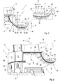
- a perspective view of a blade;
- Fig. 2
- an enlargement of part of the perspective view shown in
Fig. 1 ; - Fig. 3
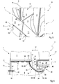
- a longitudinal section view of the blade and an enlargement of a section thereof;
- Fig. 4, 5
- perspective views of a rotor and
- Fig. 6
- a longitudinal section view of a turbine.
- Referring to
Fig. 1 ablade 1 comprises aplatform 2, wherein theplatform 2 comprises atop plate 3 carrying anairfoil 4 at the inner end of theairfoil 4. The inner end is in relation to a direction depicted by anarrow 5, wherein thearrow 5 denotes the radial direction of a shaft the blade is connected with, when assembled in arotor 6 and in aturbine 7 respectively. Thearrow 5 therefore denotes the radial direction with respect to the rotation of theblade 1. Theplatform 2 of theblade 1 further comprisesside walls 8 with respect to a circumferential direction depicted by thearrow 9, wherein saidside walls 8 form a platform cavity being enclosed by afront wall 10 and aback wall 11 of theplatform 2 with respect to a flow direction depicted by thearrow 12. The circumferential direction thereby refers to a direction of rotation of theblade 1, when assembled in therotor 6 or theturbine 7 respectively. A driving fluid flow passes theblade 1 of theturbine 7, said driving fluid flow direction defining the flow direction depicted by thearrow 12. Thus, thefront wall 10 is arranged on an upstream side of theblade 1 with respect to the flow direction given by thearrow 12, which is on the right side of the view shown inFig. 1 . The back wall is respectively arranged on a downstream side, which is the left side of the view shownFig. 1 . Theblade 1 moreover comprises afir tree form 13 arranged on abottom plate 14 of theplatform 2, wherein the term 'bottom' is given with respect to the radial direction given by thearrow 5. Thefir tree form 13 in particular is shaped to form a connection between theblade 1 and the shaft of therotor 6 and theturbine 7. Theairfoil 4 compriseschannels 15 of a channel system for cooling purposes. - The
front wall 10 comprises acurved section 16 supporting asealing section 17 of thefront wall 10. Thecurved section 16 is constructed with a radius of curvature R5 and connected to thesealing section 17 on its upstream side, wherein the radius of curvature of thecurved section 16 extends generally towards theplatform 2. The sealingsection 17 comprises a planartop side 18, wherein thetop side 18 is facing theairfoil 4. Thetop side 18 of the sealingsection 17 thus faces in the direction of thearrow 5 and thus in the radial direction and runs parallel to thetop plate 3 of theplatform 2. The sealingsection 17 further comprises fourfins top side 18. The first threefins 19 have the same size and shape, wherein the numbering of thefins flow direction 12 and thus from left to right in the shown view. Thefourth fin 20 of the sealingsection 17 is arranged at the furthermost upstream edge of the sealingsection 17 and thus on the furthest right side of the sealingsection 17 in the shown view. Thefin 20 therefore forms the tail of the sealingsection 17 on the upstream side and is formed larger than theother fins 19. All fourfins platform 2 and thus towards a direction opposing the flow direction depicted by thearrow 12. The first threefins 19 comprise inclined andplanar walls 21 which extend from thetop side 18 of the sealingsection 17 and eachfin 19 comprises aplanar surface 22 at its distal, wherein theplanar surfaces 22 run parallel to thetop side 18 of the sealingsection 17. Thefourth fin 20 comprises twowalls walls 23 facing theplatform 2 has a curved shape whereas theother wall 24 facing away from theplatform 2 has a planar surface. The transition between thetop side 18 of the sealingsection 17 and thefin 20 on the side facing theplatform 2 thus comprises a curved shape while all other transitional regions between thetop side 18 and thefins walls fin 20 extend to aplanar surface 22 at a distal end of saidfin 20, wherein saidplanar surface 22 runs parallel to thetop side 18 of the sealingsection 17 and thus thetop plate 3 of theplatform 2. - As shown in
Fig. 1, Fig. 2 andFig. 3 , thecurved section 16 is adjacent alower transition section 25 on the side of thecurved section 16 opposite to thesealing section 17. Thelower transition section 25 comprises a curved shape having the same direction of curvature as the curved section, i.e. towards the platform, but having a different radius of curvature R4. Thecurved section 16 is thus arranged between the sealingsection 17 and thelower transition section 25. Thelower transition section 25 thereby serves as a transition between thecurved section 16 and aflat section 26 of thefront wall 10. Theflat section 26 is thus arranged on the side of thelower transition section 25 opposite to thecurved section 16. Theflat section 26 thereby runs perpendicular to thetop plate 3 of theplatform 2 and thus also perpendicular to thetop side 18 of the sealingsection 17. Anupper transition section 27 is arranged on the side of theflat section 26 opposing thelower transition section 25. Theupper transition section 27 comprises a curved shape, wherein the curvature is projected away from theplatform 2 and thus in the opposite direction to the curvatures of thecurved section 16 and thelower transition section 25. Theupper transition section 27 moreover comprises a radius of curvature R3 and serves as a transition between the perpendicularly arrangedtop plate 3 andflat section 26. Thus a height H of thefront wall 10 is defined by a distance along theradial direction 5 between thetop plate 3 and thetop side 18 of the of the sealingsection 17, these being arranged in a parallel manner. - The
curved section 16, thelower transition section 25, theflat section 26 and theupper transition section 27 all have a rectangular shape and the long sides of therespective sections upper transition section 27 is however overlapped by acurved tip 28 of anairfoil transition section 29, as shown inFig. 2 , wherein theairfoil transition section 29 serves as a transition between the upstream side of theairfoil 4 and theplatform 2. Thecurved tip 28 of theairfoil transition section 29 is thereby delimited by two different radii of curvature R1, R2 at the circumferential edges of theairfoil transition section 29 and thus at its edges along the direction given by thearrow 9, wherein one of said radii of curvature R1 contacts the top long edge of theupper transition section 27 and is bigger that the other said radius of curvature R2, with the latter one running across theupper transition section 27. - In a longitudinal section view of the
blade 1 as shown inFig. 3 a flat section height H1 can be defined as the height difference between thetop plate 3 and the junction between theflat section 26 and thelower transition section 25. The respective heights H2, H3 of thefins Fig. 3 . Thus the height H2 of thefins 19 is given by their radial length and hence their dimension along the radial direction given by thearrow 5. The height H3 of thelarger fin 20 is similarly given by the corresponding dimension in the radial direction. - The
blade 1 further comprises three sealing plate guides 30, 31, 32, as shown inFig. 1 ,Fig. 4 andFig. 6 , wherein the single sealing plate guides 30, 31, 32 comprise different sizes and shapes, but all have similar fixing portions 33. Said fixing portions 33, thereby, are adapted to interact with or engage or receive acomplementary fixing part 34 of acorresponding sealing plate plate guide front wall 10 and opposing the circumferential direction. The guide of the sealingplate guide 30 is provided by three segments 38 cooperating with thebottom side 39 of thefront wall 10, said bottom side being curvilinear shaped. Thewalls 40 of the segments 38 thus cooperate with thebottom facing side 39 of thefront wall 10 to form the curvilinear shaped sealingplate guide 30, wherein thewalls 40 comprise a complementary shape to the corresponding region of thebottom side 39 of thefront wall 10. The two segments 38 arranged below thecurved section 16 and/or thesealing section 17 of thefront wall 10 moreover form the fixing portions 33 interacting with the corresponding fixingpart 34 of the corresponding sealingplate 35 in order to connect the sealingplate 35 with the sealingplate guide 30. The third segment 38 is arranged adjacent to theflat section 26 of thefront wall 10 and below theflat plate 3 of theplatform 2. This segment 38 thereby comprises twowalls 40, one of which is shaped curvilinear and complementary to thebottom side 39 of the front wall and meets theother wall 40, which is planar shaped and faces thebottom side 39 of thetop plate 3 of the platform. Thelatter wall 40 therefore forms a part of the sealingplate guide 31 arranged below thetop plate 3. Another segment 38 is arranged below thetop plate 3 in a region situated closer to theback wall 11 of theplatform 2. Said segment 38 forms the fixing portion 33 of the sealingplate guide 31 arranged below thetop plate 3 together with another segment 38 contacting and forming part of theback wall 11 and arranged perpendicular to theback wall 11. The sealingplate guide 31 thus penetrates into theback wall 11 to some extent. Said sealingplate guide 31 also penetrates into thefront wall 10 to some extent by means of aslot 41, saidslot 41 running parallel to thetop plate 3. Therefore, a corresponding sealingplate 36 arranged within the sealingplate guide 31 below thetop plate 3, is contacted by the sealingplate 35 arranged within the sealingplate guide 30 below thefront wall 10 at a side of the sealingplate 36 facing away from thetop plate 3, as shown inFig. 3, Fig. 4 andFig. 6 . Said contact is moreover provided in a region of the sealingplate 36 below thetop plate 3 which is spaced from the edge of said sealingplate 36, said edge facing thefront wall 10. This leads to a closed sealing in the transition region between thefront wall 10 and thetop plate 3. - The other
sealing plate guide 32 is arranged at a centre region of theback wall 11 of theplatform 2 and is provided by means of agroove 42 within theback wall 11. Said sealingplate guide 32 moreover runs across the whole width of theback wall 11 to allow the assembly of thesame sealing plate 37 within said sealingplate guide 32, and within a similarsealing plate guide 32 arranged at the back wall of the circumferentiallyadjacent blade 1, as shown inFig. 4 , whereinFig. 4 shows twocircumferential neighbouring blades 1 of therotor 6. The blades shown here additionally comprise circle shapedopenings 43 arranged below the sealing plate guides 32 of thecorresponding blades 1. These openings are provided in particular for cooling purposes. There is a gap between the twoblades 1 shown inFig. 4 which leads to a corresponding gap between the sealing plate guides 32 arranged at theback wall 11 of the blades, wherein said gap is crossed by the sealingplate 37. The sealingplates Fig. 4 comprise a bilayer construction, wherein the single layers run along thecorresponding sealing plates plates - A top perspective view of the rotor is shown in
Fig. 5 to reveal that theback wall 11 of thefront blade 1 comprises a step-like recess 44 at the edge of saidback wall 11 facing theback wall 11 of theneighbouring blade 1. Thelatter back wall 11 comprises a complementarily shaped step-like projection 45 facing theback wall 11 of thefront blade 1, wherein therecess 44 of theback wall 11 of thefront blade 1 receives theprojection 45 of theback wall 11 of theother blade 1. This leads to aplane contact 46 of the facing walls of therecess 44 and theprojection 45, respectively. Saidplane contact 46 thereby leads in particular to an improved sealing of the driving fluid flowing along the flow direction depicted by thearrow 12. - A
blade 1 arranged within theturbine 7 is shown inFig. 6 . The blade thereby faces an upstreamneighbouring vane 47 with respect to the flow direction of the driving fluid given by thearrow 12, wherein the sealingsection 17 is arranged below thevane 47 with respect to the radial direction given by thearrow 5 and thus as illustrated in the shown view ofFig. 6 . The sealing section and thefins part 49 of thevane 47, said cooperatingpart 49 being arranged at the bottom of thevane 47 with respect to the radial direction depicted by thearrow 5. The cooperatingpart 49 comprises a stepped shape in the shown longitudinal view section, wherein the step projecting further towards the facing sealingsection 17 cooperates with thesmaller fins 19, while the other step of the cooperatingpart 49 interacts with thebigger fin 20. -
- 1
- Blade
- 2
- Platform
- 3
- Top plate
- 4
- Airfoil
- 5
- Arrow depicting the radial direction
- 6
- Rotor
- 7
- Turbine
- 8
- Side wall
- 9
- Arrow depicting the circumferential direction
- 10
- Front wall
- 11
- Back wall
- 12
- Arrow depicting the flow direction
- 13
- Fir tree form
- 14
- Bottom plate
- 15
- Channel
- 16
- Curved section
- 17
- Sealing section
- 18
- Top side
- 19
- Fin
- 20
- Fin
- 21
- Fin wall
- 22
- Planar surface
- 23
- Fin wall
- 24
- Fin wall
- 25
- Lower transition section
- 26
- Flat section
- 27
- Upper transition section
- 28
- Curved tip
- 29
- Airfoil transition section
- 30
- Sealing plate guide
- 31
- Sealing plate guide
- 32
- Sealing plate guide
- 33
- Fixing portion
- 34
- Fixing part
- 35
- Sealing plate
- 36
- Sealing plate
- 37
- Sealing plate
- 38
- Segment
- 39
- Bottom side
- 40
- Segment Wall
- 41
- Slot
- 42
- Groove
- 43
- Opening
- 44
- Recess
- 45
- Projection
- 46
- Plane contact
- 47
- Vane
- 48
- Labyrinth sealing
- 49
- Cooperating part
Claims (15)
- A blade (1), in particular a cooled blade (1), for a turbine (7) comprising blades (1) and vanes (47), the blade (1) comprising an airfoil (4) and a platform (2) arranged at the inner end of the airfoil (4), wherein- the platform (2) comprises a top plate (3) supporting the airfoil (4),- the platform (2) comprises a front wall (10) facing an upstream neighbouring vane (47),- the front wall (10) comprises a curved section (16) supporting a sealing section (17), the sealing section (17) serving to establish a sealing between the blade (1) and the upstream neighbouring vane (47),- the front wall (10) comprises a flat section (26) which runs perpendicular to the top plate (3) and is arranged between the top plate (3) and the curved section (16).
- The blade according to claim 1,
characterized in that
a lower transition section (25) of the front wall (10) is arranged between the flat section (26) and the curved section (16). - The blade according to claim 1 or 2,
characterized in that
an upper transition section (27) of the front wall (10) is arranged between the top plate (3) and the flat section (26) of the front wall (10). - The blade according to claim 3,
characterized in that
the airfoil (4) contacts the upper transition section (27) on the upstream side by means of an airfoil transition section (29). - The blade according to one of the claims 1 to 4,
characterized in that
the sealing section (17) comprises at least one fin (19, 20) in particular to establish a labyrinth sealing (48). - The blade according to claim 5,
characterized in that
at least one of the fins (19, 20) of the sealing section is inclined towards the flat section (26) of the front wall (10) or away from the flat section (26) of the front wall (10). - The blade according to claim 5 or 6,
characterized in that
the sealing section (17) comprises several fins (19, 20) with different sizes, in particular three fins (19) having the same size and a fourth fin (20) having a larger size. - The blade according to one of the claims 1 to 7,
characterized in that
the blade (1) comprises at least one sealing plate guide (30, 31, 32) for the assembly of a sealing plate (35, 36, 37), wherein at least one of the sealing plate guides (30, 31, 32) comprises at least one fixing portion (33) adapted to cooperate with a complementary fixing part (34) of the corresponding sealing plate (35, 36, 37). - The blade according to one of the claims 1 to 8,
characterized in that
at least one of the sealing plate guides (30) comprises a curvilinear shape for receiving a complementarily shaped sealing plate (35), wherein said sealing plate guide (30) is, in particular, arranged below the front wall (10) and, in particular, extends into the sealing section (17). - The blade according to one of the claims 1 to 9,
characterized in that
at least one of the sealing plate guides (31) is arranged below the top plate (3) and adapted to receive a complementarily shaped sealing plate (36), wherein in particular the sealing plate guide (30) arranged below the front wall (10) contacts said sealing plate guide (31) arranged below the top plate (3), in particular at a position spaced from an edge of said sealing plate guide (31), said edge facing the front wall (10). - The blade according to one of the claims 1 to 10,
characterized in that
at least one of the sealing plate guides (33) is arranged at a back wall (11) of the platform (2) for the assembly of a complementarily shaped sealing plate (37), wherein said sealing plate guide (33) is in particular adapted to be aligned with respect to a sealing plate guide (37) arranged at the back wall (11) of a circumferentially adjacent blade (1), in particular for the assembly of said sealing plate (37). - The blade according one of the claims 1 to 11,
characterized in that- the back wall (11) comprises a projection (45) adapted to be arranged in a complementary recess (44) of the back wall (11) of a circumferentially neighbouring blade (1), and/or- the back wall (11) comprises a recess (44) adapted to receive a complementary projection (45) of the back wall (11) of a circumferentially neighbouring blade (1). - The blade according to one of the claims 1 to 12,
characterized in that- the airfoil transition section (29) comprises a first outer radius R1 contacting the upper transition section (27) at one end of the airfoil transition section (29) and a second outer radius R2 at the other end of the airfoil transition section (29) contacting the upper transition section (27), wherein the first radius R1 is bigger than the second radius R2,- the upper transition section (27) has a radius of curvature R3,- the lower transition section (25) has a radius of curvature R4,- the curved section (16) has a radius of curvature R5,and in a longitudinal section view- the blade (1) has a front wall height H given as the height difference between the top plate (3) and the sealing section (17) of the blade (1),- the blade (1) has a flat section height H1 given as the height difference between the top plate (3) and the junction between the flat section (26) and the lower transition section (25),wherein the blade (1) comprises at least one of the following ratios:- R1/H = 0.33 ± 20%,- R2/H = 0.317 ± 20%,- R3/H = 0.265 ± 20%,- R4/H = 0.21 ± 20%,- R5/H = 1.026 ± 20%,- H1/H = 0.57 ± 20%. - The blade according to one of the claims 1 to 13,
characterized in that
in a longitudinal section view- three out of four fins (19) of the sealing section (17) comprise a height H2,- the fourth fin (20) of the sealing section comprises a height H3,wherein the blade (1) comprises at least one of the following ratios:- H2/H = 0.11 ± 20%,- H3/H = 0.235 ± 20%. - A rotor (6), in particular for a turbine (7), comprising at least one blade (1) according to one of the claims 1 to 14, and at least one sealing plate (35, 36, 37), wherein at least one of the sealing plates (35, 36, 37) comprises a bilayer construction and/or is resilient.
Applications Claiming Priority (1)
| Application Number | Priority Date | Filing Date | Title |
|---|---|---|---|
| RU2011127159/06A RU2564741C2 (en) | 2011-07-01 | 2011-07-01 | Turbine blade and turbine rotor |
Publications (2)
| Publication Number | Publication Date |
|---|---|
| EP2540986A2 true EP2540986A2 (en) | 2013-01-02 |
| EP2540986A3 EP2540986A3 (en) | 2017-05-31 |
Family
ID=46395531
Family Applications (1)
| Application Number | Title | Priority Date | Filing Date |
|---|---|---|---|
| EP12174450.2A Withdrawn EP2540986A3 (en) | 2011-07-01 | 2012-06-29 | Turbine blade |
Country Status (2)
| Country | Link |
|---|---|
| EP (1) | EP2540986A3 (en) |
| RU (1) | RU2564741C2 (en) |
Cited By (4)
| Publication number | Priority date | Publication date | Assignee | Title |
|---|---|---|---|---|
| WO2014209464A3 (en) * | 2013-04-18 | 2015-03-12 | United Technologies Corporation | Gas turbine engine airfoil platform edge geometry |
| DE102013220467A1 (en) * | 2013-10-10 | 2015-05-07 | MTU Aero Engines AG | Rotor having a rotor body and a plurality of blades mounted thereon |
| US20160061048A1 (en) * | 2013-03-25 | 2016-03-03 | United Technologies Corporation | Rotor blade with l-shaped feather seal |
| US10851661B2 (en) | 2017-08-01 | 2020-12-01 | General Electric Company | Sealing system for a rotary machine and method of assembling same |
Family Cites Families (9)
| Publication number | Priority date | Publication date | Assignee | Title |
|---|---|---|---|---|
| CH525419A (en) * | 1970-12-18 | 1972-07-15 | Bbc Sulzer Turbomaschinen | Sealing device for turbo machines |
| US4714410A (en) * | 1986-08-18 | 1987-12-22 | Westinghouse Electric Corp. | Trailing edge support for control stage steam turbine blade |
| US5827047A (en) * | 1996-06-27 | 1998-10-27 | United Technologies Corporation | Turbine blade damper and seal |
| JP2002201913A (en) * | 2001-01-09 | 2002-07-19 | Mitsubishi Heavy Ind Ltd | Split wall of gas turbine and shroud |
| US6506016B1 (en) * | 2001-11-15 | 2003-01-14 | General Electric Company | Angel wing seals for blades of a gas turbine and methods for determining angel wing seal profiles |
| US6779972B2 (en) * | 2002-10-31 | 2004-08-24 | General Electric Company | Flowpath sealing and streamlining configuration for a turbine |
| DE102004023130A1 (en) * | 2004-05-03 | 2005-12-01 | Rolls-Royce Deutschland Ltd & Co Kg | Sealing and damping system for turbine blades |
| US7465152B2 (en) * | 2005-09-16 | 2008-12-16 | General Electric Company | Angel wing seals for turbine blades and methods for selecting stator, rotor and wing seal profiles |
| GB0808206D0 (en) * | 2008-05-07 | 2008-06-11 | Rolls Royce Plc | A blade arrangement |
-
2011
- 2011-07-01 RU RU2011127159/06A patent/RU2564741C2/en not_active IP Right Cessation
-
2012
- 2012-06-29 EP EP12174450.2A patent/EP2540986A3/en not_active Withdrawn
Non-Patent Citations (1)
| Title |
|---|
| None |
Cited By (5)
| Publication number | Priority date | Publication date | Assignee | Title |
|---|---|---|---|---|
| US20160061048A1 (en) * | 2013-03-25 | 2016-03-03 | United Technologies Corporation | Rotor blade with l-shaped feather seal |
| WO2014209464A3 (en) * | 2013-04-18 | 2015-03-12 | United Technologies Corporation | Gas turbine engine airfoil platform edge geometry |
| US10047617B2 (en) | 2013-04-18 | 2018-08-14 | United Technologies Corporation | Gas turbine engine airfoil platform edge geometry |
| DE102013220467A1 (en) * | 2013-10-10 | 2015-05-07 | MTU Aero Engines AG | Rotor having a rotor body and a plurality of blades mounted thereon |
| US10851661B2 (en) | 2017-08-01 | 2020-12-01 | General Electric Company | Sealing system for a rotary machine and method of assembling same |
Also Published As
| Publication number | Publication date |
|---|---|
| RU2011127159A (en) | 2013-01-10 |
| RU2564741C2 (en) | 2015-10-10 |
| EP2540986A3 (en) | 2017-05-31 |
Similar Documents
| Publication | Publication Date | Title |
|---|---|---|
| AU2012203822B9 (en) | Turbine vane | |
| CA2333011C (en) | A component for a gas turbine | |
| CN108884717B (en) | Turbine airfoil with turbulent flow characteristics on cold walls | |
| US6942460B2 (en) | Vane wheel for radial turbine | |
| EP2054588B1 (en) | Turbine blade assembly | |
| CN101775999B (en) | Methods and apparatus relating to improved turbine blade platform contours | |
| JP5777531B2 (en) | Airfoil blades for axial turbomachinery | |
| JP2010281320A (en) | Turbine stage | |
| EP1488078B1 (en) | Impingement cooling of gas turbine blades or vanes | |
| JP2008095695A (en) | Movable blade for turbomachine | |
| JP2005214207A (en) | Rotor blade for rotary machine | |
| CN102213112B (en) | Be supported on the row of the movable vane on machine rotors and around sealing system between stationary housing | |
| CN104704201B (en) | Seals in turbines of combustion turbine engines | |
| US20150064020A1 (en) | Turbine blade or vane with separate endwall | |
| US20110293402A1 (en) | Gas turbine | |
| ES2897722T3 (en) | Turbine mounting for impact cooling and mounting method | |
| CN111412178B (en) | Improved inter-vane platform seal | |
| JP5980137B2 (en) | Turbine blade | |
| RU2564741C2 (en) | Turbine blade and turbine rotor | |
| JP2021050734A (en) | Blade of turbomachine | |
| JP2018128018A (en) | Pre-swirler device for gas turbine | |
| JP5357601B2 (en) | Turbine blade | |
| CN105485056A (en) | Stator blade mounting structure of air compressor | |
| CN1997810B (en) | Blades or vanes of rotating machinery | |
| CN116988852A (en) | The stepped structure of the casing reduces the heat transfer coefficient of the grooved tip of the turbine moving blade. |
Legal Events
| Date | Code | Title | Description |
|---|---|---|---|
| PUAI | Public reference made under article 153(3) epc to a published international application that has entered the european phase |
Free format text: ORIGINAL CODE: 0009012 |
|
| AK | Designated contracting states |
Kind code of ref document: A2 Designated state(s): AL AT BE BG CH CY CZ DE DK EE ES FI FR GB GR HR HU IE IS IT LI LT LU LV MC MK MT NL NO PL PT RO RS SE SI SK SM TR |
|
| AX | Request for extension of the european patent |
Extension state: BA ME |
|
| RAP1 | Party data changed (applicant data changed or rights of an application transferred) |
Owner name: GENERAL ELECTRIC TECHNOLOGY GMBH |
|
| PUAL | Search report despatched |
Free format text: ORIGINAL CODE: 0009013 |
|
| AK | Designated contracting states |
Kind code of ref document: A3 Designated state(s): AL AT BE BG CH CY CZ DE DK EE ES FI FR GB GR HR HU IE IS IT LI LT LU LV MC MK MT NL NO PL PT RO RS SE SI SK SM TR |
|
| AX | Request for extension of the european patent |
Extension state: BA ME |
|
| RIC1 | Information provided on ipc code assigned before grant |
Ipc: F01D 11/02 20060101AFI20170425BHEP Ipc: F01D 11/00 20060101ALI20170425BHEP |
|
| STAA | Information on the status of an ep patent application or granted ep patent |
Free format text: STATUS: THE APPLICATION IS DEEMED TO BE WITHDRAWN |
|
| 18D | Application deemed to be withdrawn |
Effective date: 20171201 |