EP2540618A1 - Filler panel for bulkhead to skin joint in integral tanks - Google Patents
Filler panel for bulkhead to skin joint in integral tanks Download PDFInfo
- Publication number
- EP2540618A1 EP2540618A1 EP12173665A EP12173665A EP2540618A1 EP 2540618 A1 EP2540618 A1 EP 2540618A1 EP 12173665 A EP12173665 A EP 12173665A EP 12173665 A EP12173665 A EP 12173665A EP 2540618 A1 EP2540618 A1 EP 2540618A1
- Authority
- EP
- European Patent Office
- Prior art keywords
- stringers
- lifting surface
- skins
- bulkheads
- aircraft lifting
- Prior art date
- Legal status (The legal status is an assumption and is not a legal conclusion. Google has not performed a legal analysis and makes no representation as to the accuracy of the status listed.)
- Granted
Links
- 239000000945 filler Substances 0.000 title claims abstract description 32
- 239000002828 fuel tank Substances 0.000 claims abstract description 12
- XAGFODPZIPBFFR-UHFFFAOYSA-N aluminium Chemical compound [Al] XAGFODPZIPBFFR-UHFFFAOYSA-N 0.000 claims description 3
- 229910052782 aluminium Inorganic materials 0.000 claims description 3
- 210000000988 bone and bone Anatomy 0.000 claims description 3
- 102100040287 GTP cyclohydrolase 1 feedback regulatory protein Human genes 0.000 claims 1
- 101710185324 GTP cyclohydrolase 1 feedback regulatory protein Proteins 0.000 claims 1
- 239000004918 carbon fiber reinforced polymer Substances 0.000 claims 1
- 229920002430 Fibre-reinforced plastic Polymers 0.000 description 5
- 238000007789 sealing Methods 0.000 description 4
- OKTJSMMVPCPJKN-UHFFFAOYSA-N Carbon Chemical compound [C] OKTJSMMVPCPJKN-UHFFFAOYSA-N 0.000 description 3
- 229910052799 carbon Inorganic materials 0.000 description 3
- 239000011151 fibre-reinforced plastic Substances 0.000 description 3
- 239000003365 glass fiber Substances 0.000 description 2
- 239000002131 composite material Substances 0.000 description 1
- 238000006073 displacement reaction Methods 0.000 description 1
- 239000000446 fuel Substances 0.000 description 1
- 238000004519 manufacturing process Methods 0.000 description 1
- 239000011159 matrix material Substances 0.000 description 1
- 238000012986 modification Methods 0.000 description 1
- 230000004048 modification Effects 0.000 description 1
- 239000003351 stiffener Substances 0.000 description 1
Images


Classifications
-
- B—PERFORMING OPERATIONS; TRANSPORTING
- B64—AIRCRAFT; AVIATION; COSMONAUTICS
- B64C—AEROPLANES; HELICOPTERS
- B64C3/00—Wings
- B64C3/18—Spars; Ribs; Stringers
- B64C3/182—Stringers, longerons
-
- B—PERFORMING OPERATIONS; TRANSPORTING
- B64—AIRCRAFT; AVIATION; COSMONAUTICS
- B64C—AEROPLANES; HELICOPTERS
- B64C3/00—Wings
- B64C3/34—Tanks constructed integrally with wings, e.g. for fuel or water
Definitions
- This invention refers to the skins of aircraft fuel tanks and, more in particular, to filler panels attached to them on the intersection areas with the fuel tank bulkheads, between contiguous stringers.
- the main structure for aircraft lifting surfaces mainly consists of a leading edge, a torsion box, a trailing edge, a root joint and a wing tip.
- the torsion box in turn consists of several structural elements: upper and lower skins stiffened by stringers on one side; spars and ribs on the other side.
- the structural elements forming the torsion box are manufactured separately and are joined with the aid of complicated tooling to achieve the necessary tolerances, which are given by the aerodynamic, assembly and structural requirements.
- CFRP Carbon Fibre Reinforced Plastic
- the skins which make up the torsion boxes are stiffened with span wise longitudinal stringers that improve both the strength and the buckling behaviour of the skins having different cross sections such as "T", "I” or “J” shaped crass sections.
- Full height of stringer benefits the stability of the panel by means of a bigger inertia in the stiffening element.
- Aircraft fuel tanks are usually housed in the torsion box of the aircraft wing. They are usually delimited by bulkheads following rib and stringer traces.
- This invention is focused on the solution of this problem.
- One object of the present invention is to provide an aircraft lifting surface comprising one or more fuel tanks delimited by watertight bulkheads easy to assemble.
- Another object of the present invention is to provide an aircraft lifting surface comprising one or more fuel tanks delimited by watertight bulkheads with a limited number of riveted unions.
- an aircraft lifting surface such as a wing, structured as a torsion box comprising upper and lower skins stiffened by span wise stringers, span wise front and rear spars and chord wise ribs, said aircraft lifting surface comprising one or more fuel tanks arranged inside of said torsion box and separated by bulkheads, the stringers having extended feet in the intersection areas with said bulkheads, also comprising filler panels of said skins covering the holes that remain between said skins and said bulkheads outside said intersection areas whose configuration is adapted for covering the space between the extended feet of contiguous stringers, leaving a gap with them of a predetermined width 1, thereby providing a self-fastening capability over each skin plane that facilitates the attachment of said filler panels to said skins.
- said predetermined width W1 between a filler panel and the borders of the extended feet of contiguous stringers is comprised between 2-4 mm.
- said skins and said stringers are made of Carbon Fibre Reinforced Plastic (CFRP), said bulkheads are made of aluminum and said filler panels are made of Glass Fibre Reinforced Plastic (GFRP).
- CFRP Carbon Fibre Reinforced Plastic
- GFRP Glass Fibre Reinforced Plastic
- said stringers are T-shaped stringers
- said extended feet have an arched shape with a symmetry axis on the trace of each intersected bulkhead and said filler panels have a "dog bone” shape adapted to said arched shape.
- each border of said extended feet comprise a central straight segment and two curved segments and each border of said filler panels comprise a central straight segment, two curved intermediate segments and two end straight segments of a predetermined length W2 (preferably comprised between 10-14 mm), displaced at a predetermined perpendicular distance W3 (preferably comprised between 20-30 mm) from said central straight segment.
- W2 preferably comprised between 10-14 mm
- W3 preferably comprised between 20-30 mm
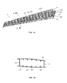
- a multi-rib torsion box 1 such as the one depicted in Figures 1 a and 1 b is structurally based on a span wise front spar 11 and a span wise rear spar 13 (understanding the terms front and rear in relation to the flight direction of the aircraft), a plurality of chord wise ribs 27, 27', 27", 27"' and the upper and lower skins 19, 21 with a plurality of span wise stringers 25, 25', 25".
- ribs 27, 27', 27", 27"' The main functions of ribs 27, 27', 27", 27"' is to provide torsion rigidity and to limit the skins 19, 21 and the stringers 25, 25', 25" longitudinally so as to discretize the buckling loads and maintain the shape of the aerodynamic surface.
- the primary function of the skins 19, 21 is to provide a continuous surface to give support and distribute the aerodynamic loads and, thus, it is structured as a set of panels delimited by said ribs 27, 27', 27", 27"' and said stringers 25, 25', 25" as well as the front spar 11 and the rear spar 13.
- Figure 2 shows the left part of the torsion box of an aircraft wing housing a centre tank 31, an outboard tank 33 a surge tank 35 and also an small tank 37 where is located the fuel pump. Said tanks are separated by bulkheads 41 following rib or stringer traces.
- the bulkheads 41 and the ribs 27, 27', 27", 27"' have a similar structure but the bulkheads 41 shall be watertight, as they are the tank walls.
- Figure 3 shows an intersection area of, for instance, the lower skin 21 with one of said bulkheads 41 represented by its trace 43 between two contiguous stringers 25, 25'.
- the stringers 25, 25' have extended feet 26, 26' in a similar way to the intersections between stringers and ribs for providing space for the stringer-rib-skin unions.
- said extended feet 26, 26' have typical arched borders.
- a filler panel 45 dimensioned for covering the space between said extended feet 26, 26', leaving a gap W1 between their borders, is attached to the skin 21.
- Said filler panel 45 has a "dog bone” shape determined by the arched borders of the extended feet 26, 26' that provides a self-fastening capability over the skin plane, i.e. the filler panel 45 is embraced by the contiguous extended feet 26, 26' preventing its displacement over the skin surface.
- the arched borders of the extended feet 26, 26' comprise a central straight segment 27 and two curved segments 28, 29 and the opposed borders of the filler panels 45 comprise a central straight segment 47, two curved intermediate segments 48, 49 and two end straight segments 50, 51 of a length W2, displaced at a perpendicular distance W3 from said central straight segment 47.
- Figure 5 shows an intersection area with a filler panel 45 in the lower skin 21 and Figure 6 shows how said filler panel 45 is attached to the lower skin 21 using a first sealing means 51 and how the gaps with the borders of the extended feet 26, 26' are sealed with a second sealing means 53 of a lesser density than said first sealing means 51.
Landscapes
- Engineering & Computer Science (AREA)
- Mechanical Engineering (AREA)
- Aviation & Aerospace Engineering (AREA)
- Laminated Bodies (AREA)
- Connection Of Plates (AREA)
- Moulding By Coating Moulds (AREA)
Abstract
Description
- This invention refers to the skins of aircraft fuel tanks and, more in particular, to filler panels attached to them on the intersection areas with the fuel tank bulkheads, between contiguous stringers.
- The main structure for aircraft lifting surfaces mainly consists of a leading edge, a torsion box, a trailing edge, a root joint and a wing tip. The torsion box in turn consists of several structural elements: upper and lower skins stiffened by stringers on one side; spars and ribs on the other side. Typically, the structural elements forming the torsion box are manufactured separately and are joined with the aid of complicated tooling to achieve the necessary tolerances, which are given by the aerodynamic, assembly and structural requirements.
- Nowadays, and particularly in the aeronautical industry, composite materials with an organic matrix and continuous fibres, especially CFRP (Carbon Fibre Reinforced Plastic) are widely used in a great variety of structural elements. For example, all the elements which make up the torsion box enumerated beforehand (ribs, stringers, spars and skins) can be manufactured using CFRP.
- The skins which make up the torsion boxes are stiffened with span wise longitudinal stringers that improve both the strength and the buckling behaviour of the skins having different cross sections such as "T", "I" or "J" shaped crass sections. Full height of stringer benefits the stability of the panel by means of a bigger inertia in the stiffening element.
- Aircraft fuel tanks are usually housed in the torsion box of the aircraft wing. They are usually delimited by bulkheads following rib and stringer traces.
- The design and manufacture of said torsion boxes involves several problems. One of them is the sealing of the holes that remain between the skins and the bulkheads close to the intersection areas between bulkheads and stringers.
- One known solution for said problem is attaching to the skins filler panels covering said holes by means of rivets. An important drawback of this solution is that requires a riveting operation during the assembly of the torsion box of the wing that involves time and costs.
- This invention is focused on the solution of this problem.
- One object of the present invention is to provide an aircraft lifting surface comprising one or more fuel tanks delimited by watertight bulkheads easy to assemble.
- Another object of the present invention is to provide an aircraft lifting surface comprising one or more fuel tanks delimited by watertight bulkheads with a limited number of riveted unions.
- These and another objects are met by an aircraft lifting surface, such as a wing, structured as a torsion box comprising upper and lower skins stiffened by span wise stringers, span wise front and rear spars and chord wise ribs, said aircraft lifting surface comprising one or more fuel tanks arranged inside of said torsion box and separated by bulkheads, the stringers having extended feet in the intersection areas with said bulkheads, also comprising filler panels of said skins covering the holes that remain between said skins and said bulkheads outside said intersection areas whose configuration is adapted for covering the space between the extended feet of contiguous stringers, leaving a gap with them of a
predetermined width 1, thereby providing a self-fastening capability over each skin plane that facilitates the attachment of said filler panels to said skins. - In embodiments of the present invention wherein said predetermined width W1 between a filler panel and the borders of the extended feet of contiguous stringers is comprised between 2-4 mm. Hereby it is achieved an aircraft lifting surface with a minimum gap between the extended feet of contiguous stringers and said filler panels for allowing its attachment to the skin without compromising said self-fastening capability.
- In embodiments of the present invention said skins and said stringers are made of Carbon Fibre Reinforced Plastic (CFRP), said bulkheads are made of aluminum and said filler panels are made of Glass Fibre Reinforced Plastic (GFRP). Hereby it is achieved an aircraft lifting surface having self-fastening low-weight filler panels for covering the holes between the skins and the bulkheads.
- In embodiments of the present invention said stringers are T-shaped stringers, said extended feet have an arched shape with a symmetry axis on the trace of each intersected bulkhead and said filler panels have a "dog bone" shape adapted to said arched shape. Hereby it is achieved an aircraft lifting surface having filler panels suitable shaped for being incorporated to skins stiffened with T-shaped stringers.
- In embodiments of the present invention each border of said extended feet comprise a central straight segment and two curved segments and each border of said filler panels comprise a central straight segment, two curved intermediate segments and two end straight segments of a predetermined length W2 (preferably comprised between 10-14 mm), displaced at a predetermined perpendicular distance W3 (preferably comprised between 20-30 mm) from said central straight segment. Hereby it is achieved an aircraft lifting surface having filler panels of an optimized configuration for being incorporated to skins stiffened with T-shaped stringers.
- Other characteristics and advantages of the present invention will be clear from the following detailed description of embodiments illustrative of its object in relation to the attached figures.
-
-
Figure 1a is a perspective view of a known multi-rib torsion box of an aircraft wing andFigure 1b is a cross-section view ofFigure 1 a along plane A-A. -
Figure 2 is a plan view of a left part of an aircraft wing showing the position of a centre fuel tank, an outboard fuel tank, a surge tank and a small tank. -
Figure 3 is a plan view of a wing skin in an intersection area between one fuel tank bulkhead and two contiguous stringers incorporating a filler panel according to the present invention. -
Figure 4 is an enlarged view of said filler panel. -
Figure 5 is a transversal section of said intersection area in the lower wing skin. -
Figure 6 is an enlarged view of the filler panel according to the present invention attached to the lower wing skin. - The invention relates to fuel tanks housed in a multi-rib torsion box structure with longitudinal stiffeners having preferably a T-shaped cross-section. A
multi-rib torsion box 1 such as the one depicted inFigures 1 a and 1 b is structurally based on a spanwise front spar 11 and a span wise rear spar 13 (understanding the terms front and rear in relation to the flight direction of the aircraft), a plurality of chordwise ribs lower skins wise stringers - The main functions of
ribs skins stringers - The primary function of the
skins said ribs stringers rear spar 13. -
Figure 2 shows the left part of the torsion box of an aircraft wing housing acentre tank 31, an outboard tank 33 asurge tank 35 and also ansmall tank 37 where is located the fuel pump. Said tanks are separated bybulkheads 41 following rib or stringer traces. Thebulkheads 41 and theribs bulkheads 41 shall be watertight, as they are the tank walls. -
Figure 3 shows an intersection area of, for instance, thelower skin 21 with one of saidbulkheads 41 represented by itstrace 43 between twocontiguous stringers 25, 25'. - In said intersection area, the
stringers 25, 25' have extendedfeet 26, 26' in a similar way to the intersections between stringers and ribs for providing space for the stringer-rib-skin unions. As represented inFigure 3 said extendedfeet 26, 26' have typical arched borders. - According to an embodiment of this invention in said intersection area a
filler panel 45, dimensioned for covering the space between said extendedfeet 26, 26', leaving a gap W1 between their borders, is attached to theskin 21. Saidfiller panel 45 has a "dog bone" shape determined by the arched borders of the extendedfeet 26, 26' that provides a self-fastening capability over the skin plane, i.e. thefiller panel 45 is embraced by the contiguous extendedfeet 26, 26' preventing its displacement over the skin surface. - In a preferred embodiment, the arched borders of the extended
feet 26, 26' comprise a centralstraight segment 27 and twocurved segments filler panels 45 comprise a centralstraight segment 47, two curvedintermediate segments straight segments straight segment 47. -
Figure 5 shows an intersection area with afiller panel 45 in thelower skin 21 andFigure 6 shows how saidfiller panel 45 is attached to thelower skin 21 using a first sealing means 51 and how the gaps with the borders of the extendedfeet 26, 26' are sealed with a second sealing means 53 of a lesser density than said first sealing means 51. - In preferred embodiments of the invention:
- The
stringers skins - The
bulkheads 41 are made of aluminum. - The
filler panels 45 are made of Glass Fibre Reinforced Plastic (GFRP). - W1 is comprised between 2-4 mm.
- W2 is comprised between 10-14 mm.
- W3 is comprised between 20-30 mm.
- Although the present invention has been fully described in connection with preferred embodiments, it is evident that modifications may be introduced within the scope thereof, not considering this as limited by these embodiments, but by the contents of the following claims.
Claims (7)
- An aircraft lifting surface structured as a torsion box comprising upper and lower skins (19, 21) stiffened by span wise stringers (25, 25', 25"), span wise front and rear spars (11, 13) and chord wise ribs (27, 27', 27"), said aircraft lifting surface comprising one or more fuel tanks (31, 33, 35, 37) arranged inside of said torsion box and separated by bulkheads (41), the stringers (25, 25', 25") having extended feet in the intersection areas with said bulkheads (41), also comprising filler panels (45) of said skins (19, 21) covering the holes that remain between said skins (19, 21) and said bulkheads (41) outside said intersection areas, characterized in that the configuration of said filler panels (45) is adapted for covering the space between the extended feet (26, 26') of contiguous stringers (25, 25'), leaving a gap with them of a predetermined width (W1), thereby providing a self-fastening capability over each skin plane that facilitates the attachment of said filler panels (45) to said skins (19, 21).
- An aircraft lifting surface according to claim 1, wherein said predetermined width (W1) between a filler panel (45) and the borders of the extended feet (26, 26') of contiguous stringers (25, 25') is comprised between 2-4 mm.
- An aircraft lifting surface according to any of claims 1-2, wherein said skins (19, 21) and said stringers (25, 25', 25") are made of CFRP, said bulkheads (41) are made of aluminum and said filler panels (45) are made of GFRP.
- An aircraft lifting surface according to any of claims 1-3, wherein said stringers (25, 25', 25") are T-shaped stringers, said extended feet have an arched shape with a symmetry axis an the trace of each intersected bulkhead (41) and said filler panels (45) have a "dog bone" shape adapted to said arched shape.
- An aircraft lifting surface according to claim 4, wherein:- each border of said extended feet comprise a central straight segment (27) and two curved segments (28, 29);- each border of said filler panels (45) comprise a central straight segment (47), two curved intermediate segments (48, 49) and two end straight segments (50, 51) of a predetermined length (W2), displaced at a predetermined perpendicular distance (W3) from said central straight segment (47).
- An aircraft lifting surface according to claim 5, wherein:- said predetermined length (W2) is comprised between 10-14 mm;- said predetermined perpendicular distance (W3) is comprised between 20-30 mm.
- An aircraft lifting surface according to any of claims 1-6, wherein the lifting surface is a wing.
Applications Claiming Priority (1)
| Application Number | Priority Date | Filing Date | Title |
|---|---|---|---|
| ES201131101A ES2401830B1 (en) | 2011-06-29 | 2011-06-29 | FILLING PANELS FOR COATINGS OF AIRCRAFT FUEL TANKS. |
Publications (2)
| Publication Number | Publication Date |
|---|---|
| EP2540618A1 true EP2540618A1 (en) | 2013-01-02 |
| EP2540618B1 EP2540618B1 (en) | 2014-10-22 |
Family
ID=46331080
Family Applications (1)
| Application Number | Title | Priority Date | Filing Date |
|---|---|---|---|
| EP12173665.6A Not-in-force EP2540618B1 (en) | 2011-06-29 | 2012-06-26 | Filler panel for bulkhead to skin joint in integral tanks |
Country Status (3)
| Country | Link |
|---|---|
| US (1) | US20130001363A1 (en) |
| EP (1) | EP2540618B1 (en) |
| ES (1) | ES2401830B1 (en) |
Families Citing this family (4)
| Publication number | Priority date | Publication date | Assignee | Title |
|---|---|---|---|---|
| CN110525631B (en) * | 2019-08-22 | 2021-06-01 | 中国商用飞机有限责任公司北京民用飞机技术研究中心 | A kind of sealing structure and fastening method with preset gap |
| EP3805091B1 (en) * | 2019-10-08 | 2021-08-25 | AIRBUS HELICOPTERS DEUTSCHLAND GmbH | A bulkhead for a boom of an aircraft |
| US11591061B2 (en) | 2020-12-02 | 2023-02-28 | Airbus Helicopters Deutschland GmbH | Watertight bulkhead for a boom of an aircraft |
| CN114228975B (en) * | 2022-01-20 | 2024-07-30 | 湖南航天环宇通信科技股份有限公司 | Multi-cabin integral oil tank of unmanned aerial vehicle |
Citations (4)
| Publication number | Priority date | Publication date | Assignee | Title |
|---|---|---|---|---|
| US5983945A (en) * | 1993-10-22 | 1999-11-16 | The United States Of America As Represented By The Secretary Of Transportation | Wing tank liner |
| US20050236524A1 (en) * | 2004-04-27 | 2005-10-27 | The Boeing Company | Airfoil box and associated method |
| US20060226287A1 (en) * | 2004-04-06 | 2006-10-12 | Kent Grantham | Structural panels for use in aircraft fuselages and other structures |
| US20080179461A1 (en) * | 2006-10-31 | 2008-07-31 | Airbus Deutschland Gmbh | Stiffening element for an aircraft or spacecraft, and method for its production |
Family Cites Families (5)
| Publication number | Priority date | Publication date | Assignee | Title |
|---|---|---|---|---|
| US2241972A (en) * | 1937-02-08 | 1941-05-13 | Messerschmitt Boelkow Blohm | Structure of aircraft surfaces |
| US4828202A (en) * | 1979-09-27 | 1989-05-09 | The Boeing Company | Method and apparatus for wideband vibration damping of reinforced skin structures |
| US4749155A (en) * | 1985-09-30 | 1988-06-07 | The Boeing Company | Method of making wing box cover panel |
| US7325771B2 (en) * | 2004-09-23 | 2008-02-05 | The Boeing Company | Splice joints for composite aircraft fuselages and other structures |
| ES2395604B1 (en) * | 2010-10-29 | 2013-12-26 | Airbus Operations, S.L. | INTERNAL REPAIR FOLDED. |
-
2011
- 2011-06-29 ES ES201131101A patent/ES2401830B1/en not_active Expired - Fee Related
- 2011-12-28 US US13/339,101 patent/US20130001363A1/en not_active Abandoned
-
2012
- 2012-06-26 EP EP12173665.6A patent/EP2540618B1/en not_active Not-in-force
Patent Citations (4)
| Publication number | Priority date | Publication date | Assignee | Title |
|---|---|---|---|---|
| US5983945A (en) * | 1993-10-22 | 1999-11-16 | The United States Of America As Represented By The Secretary Of Transportation | Wing tank liner |
| US20060226287A1 (en) * | 2004-04-06 | 2006-10-12 | Kent Grantham | Structural panels for use in aircraft fuselages and other structures |
| US20050236524A1 (en) * | 2004-04-27 | 2005-10-27 | The Boeing Company | Airfoil box and associated method |
| US20080179461A1 (en) * | 2006-10-31 | 2008-07-31 | Airbus Deutschland Gmbh | Stiffening element for an aircraft or spacecraft, and method for its production |
Also Published As
| Publication number | Publication date |
|---|---|
| ES2401830B1 (en) | 2014-04-10 |
| US20130001363A1 (en) | 2013-01-03 |
| ES2401830A1 (en) | 2013-04-24 |
| EP2540618B1 (en) | 2014-10-22 |
Similar Documents
| Publication | Publication Date | Title |
|---|---|---|
| EP2848519B1 (en) | Upper joints between outboard wing boxes and wing center sections of aircraft wing assemblies | |
| US8276848B2 (en) | Rib structure for torsion boxes of a wing or horizontal stabiliser of an aircraft | |
| EP2634093A1 (en) | Filler panels for aircraft fuel tank coverings | |
| KR102024396B1 (en) | Lower joints between outboard wing boxes and center wing sections of aircraft wing assemblies | |
| EP2173615B1 (en) | Stiffened multispar torsion box | |
| EP2842867B1 (en) | Composite control surfaces for aircraft | |
| US20170152013A1 (en) | Aircraft side of body joint | |
| US20080223987A1 (en) | Rib element and composite flange for aircraft | |
| US9827737B2 (en) | Composite structural element and torsion box | |
| EP2786932A2 (en) | Continuously curved spar and method of manufacturing | |
| EP2540618B1 (en) | Filler panel for bulkhead to skin joint in integral tanks | |
| CN115535211A (en) | Aircraft and method of manufacturing an aircraft | |
| US20150175253A1 (en) | Leading edge for an aircraft lifting surface | |
| US12077289B2 (en) | Aircraft assembly having an integral spar-cover | |
| CN103429492B (en) | Torsion box skin stiffened with non-parallel stringers | |
| EP2886450B1 (en) | Aircraft control surface | |
| ES2953735T3 (en) | Trailing edge for a composite multi-spar integrated lifting surface and manufacturing method of said trailing edge | |
| EP2626291B1 (en) | Structural joint having continuous skin with inside and outside stringers | |
| RU2481243C1 (en) | Aircraft wing and outer wing joint assembly | |
| EP2457823B1 (en) | An aircraft lifting surface skin |
Legal Events
| Date | Code | Title | Description |
|---|---|---|---|
| PUAI | Public reference made under article 153(3) epc to a published international application that has entered the european phase |
Free format text: ORIGINAL CODE: 0009012 |
|
| AK | Designated contracting states |
Kind code of ref document: A1 Designated state(s): AL AT BE BG CH CY CZ DE DK EE ES FI FR GB GR HR HU IE IS IT LI LT LU LV MC MK MT NL NO PL PT RO RS SE SI SK SM TR |
|
| AX | Request for extension of the european patent |
Extension state: BA ME |
|
| 17P | Request for examination filed |
Effective date: 20130702 |
|
| RBV | Designated contracting states (corrected) |
Designated state(s): AL AT BE BG CH CY CZ DE DK EE ES FI FR GB GR HR HU IE IS IT LI LT LU LV MC MK MT NL NO PL PT RO RS SE SI SK SM TR |
|
| GRAP | Despatch of communication of intention to grant a patent |
Free format text: ORIGINAL CODE: EPIDOSNIGR1 |
|
| INTG | Intention to grant announced |
Effective date: 20140513 |
|
| GRAS | Grant fee paid |
Free format text: ORIGINAL CODE: EPIDOSNIGR3 |
|
| GRAA | (expected) grant |
Free format text: ORIGINAL CODE: 0009210 |
|
| AK | Designated contracting states |
Kind code of ref document: B1 Designated state(s): AL AT BE BG CH CY CZ DE DK EE ES FI FR GB GR HR HU IE IS IT LI LT LU LV MC MK MT NL NO PL PT RO RS SE SI SK SM TR |
|
| REG | Reference to a national code |
Ref country code: GB Ref legal event code: FG4D |
|
| REG | Reference to a national code |
Ref country code: CH Ref legal event code: EP |
|
| REG | Reference to a national code |
Ref country code: AT Ref legal event code: REF Ref document number: 692497 Country of ref document: AT Kind code of ref document: T Effective date: 20141115 |
|
| REG | Reference to a national code |
Ref country code: IE Ref legal event code: FG4D |
|
| REG | Reference to a national code |
Ref country code: DE Ref legal event code: R096 Ref document number: 602012003469 Country of ref document: DE Effective date: 20141204 |
|
| REG | Reference to a national code |
Ref country code: NL Ref legal event code: VDEP Effective date: 20141022 |
|
| REG | Reference to a national code |
Ref country code: AT Ref legal event code: MK05 Ref document number: 692497 Country of ref document: AT Kind code of ref document: T Effective date: 20141022 |
|
| REG | Reference to a national code |
Ref country code: LT Ref legal event code: MG4D |
|
| PG25 | Lapsed in a contracting state [announced via postgrant information from national office to epo] |
Ref country code: NO Free format text: LAPSE BECAUSE OF FAILURE TO SUBMIT A TRANSLATION OF THE DESCRIPTION OR TO PAY THE FEE WITHIN THE PRESCRIBED TIME-LIMIT Effective date: 20150122 Ref country code: NL Free format text: LAPSE BECAUSE OF FAILURE TO SUBMIT A TRANSLATION OF THE DESCRIPTION OR TO PAY THE FEE WITHIN THE PRESCRIBED TIME-LIMIT Effective date: 20141022 Ref country code: IS Free format text: LAPSE BECAUSE OF FAILURE TO SUBMIT A TRANSLATION OF THE DESCRIPTION OR TO PAY THE FEE WITHIN THE PRESCRIBED TIME-LIMIT Effective date: 20150222 Ref country code: LT Free format text: LAPSE BECAUSE OF FAILURE TO SUBMIT A TRANSLATION OF THE DESCRIPTION OR TO PAY THE FEE WITHIN THE PRESCRIBED TIME-LIMIT Effective date: 20141022 Ref country code: FI Free format text: LAPSE BECAUSE OF FAILURE TO SUBMIT A TRANSLATION OF THE DESCRIPTION OR TO PAY THE FEE WITHIN THE PRESCRIBED TIME-LIMIT Effective date: 20141022 Ref country code: ES Free format text: LAPSE BECAUSE OF FAILURE TO SUBMIT A TRANSLATION OF THE DESCRIPTION OR TO PAY THE FEE WITHIN THE PRESCRIBED TIME-LIMIT Effective date: 20141022 Ref country code: PT Free format text: LAPSE BECAUSE OF FAILURE TO SUBMIT A TRANSLATION OF THE DESCRIPTION OR TO PAY THE FEE WITHIN THE PRESCRIBED TIME-LIMIT Effective date: 20150223 |
|
| PG25 | Lapsed in a contracting state [announced via postgrant information from national office to epo] |
Ref country code: GR Free format text: LAPSE BECAUSE OF FAILURE TO SUBMIT A TRANSLATION OF THE DESCRIPTION OR TO PAY THE FEE WITHIN THE PRESCRIBED TIME-LIMIT Effective date: 20150123 Ref country code: AT Free format text: LAPSE BECAUSE OF FAILURE TO SUBMIT A TRANSLATION OF THE DESCRIPTION OR TO PAY THE FEE WITHIN THE PRESCRIBED TIME-LIMIT Effective date: 20141022 Ref country code: HR Free format text: LAPSE BECAUSE OF FAILURE TO SUBMIT A TRANSLATION OF THE DESCRIPTION OR TO PAY THE FEE WITHIN THE PRESCRIBED TIME-LIMIT Effective date: 20141022 Ref country code: PL Free format text: LAPSE BECAUSE OF FAILURE TO SUBMIT A TRANSLATION OF THE DESCRIPTION OR TO PAY THE FEE WITHIN THE PRESCRIBED TIME-LIMIT Effective date: 20141022 Ref country code: LV Free format text: LAPSE BECAUSE OF FAILURE TO SUBMIT A TRANSLATION OF THE DESCRIPTION OR TO PAY THE FEE WITHIN THE PRESCRIBED TIME-LIMIT Effective date: 20141022 Ref country code: RS Free format text: LAPSE BECAUSE OF FAILURE TO SUBMIT A TRANSLATION OF THE DESCRIPTION OR TO PAY THE FEE WITHIN THE PRESCRIBED TIME-LIMIT Effective date: 20141022 Ref country code: SE Free format text: LAPSE BECAUSE OF FAILURE TO SUBMIT A TRANSLATION OF THE DESCRIPTION OR TO PAY THE FEE WITHIN THE PRESCRIBED TIME-LIMIT Effective date: 20141022 Ref country code: CY Free format text: LAPSE BECAUSE OF FAILURE TO SUBMIT A TRANSLATION OF THE DESCRIPTION OR TO PAY THE FEE WITHIN THE PRESCRIBED TIME-LIMIT Effective date: 20141022 |
|
| REG | Reference to a national code |
Ref country code: FR Ref legal event code: PLFP Year of fee payment: 4 |
|
| REG | Reference to a national code |
Ref country code: DE Ref legal event code: R097 Ref document number: 602012003469 Country of ref document: DE |
|
| PG25 | Lapsed in a contracting state [announced via postgrant information from national office to epo] |
Ref country code: CZ Free format text: LAPSE BECAUSE OF FAILURE TO SUBMIT A TRANSLATION OF THE DESCRIPTION OR TO PAY THE FEE WITHIN THE PRESCRIBED TIME-LIMIT Effective date: 20141022 Ref country code: DK Free format text: LAPSE BECAUSE OF FAILURE TO SUBMIT A TRANSLATION OF THE DESCRIPTION OR TO PAY THE FEE WITHIN THE PRESCRIBED TIME-LIMIT Effective date: 20141022 Ref country code: EE Free format text: LAPSE BECAUSE OF FAILURE TO SUBMIT A TRANSLATION OF THE DESCRIPTION OR TO PAY THE FEE WITHIN THE PRESCRIBED TIME-LIMIT Effective date: 20141022 Ref country code: SK Free format text: LAPSE BECAUSE OF FAILURE TO SUBMIT A TRANSLATION OF THE DESCRIPTION OR TO PAY THE FEE WITHIN THE PRESCRIBED TIME-LIMIT Effective date: 20141022 Ref country code: RO Free format text: LAPSE BECAUSE OF FAILURE TO SUBMIT A TRANSLATION OF THE DESCRIPTION OR TO PAY THE FEE WITHIN THE PRESCRIBED TIME-LIMIT Effective date: 20141022 |
|
| PLBE | No opposition filed within time limit |
Free format text: ORIGINAL CODE: 0009261 |
|
| STAA | Information on the status of an ep patent application or granted ep patent |
Free format text: STATUS: NO OPPOSITION FILED WITHIN TIME LIMIT |
|
| PG25 | Lapsed in a contracting state [announced via postgrant information from national office to epo] |
Ref country code: IT Free format text: LAPSE BECAUSE OF FAILURE TO SUBMIT A TRANSLATION OF THE DESCRIPTION OR TO PAY THE FEE WITHIN THE PRESCRIBED TIME-LIMIT Effective date: 20141022 |
|
| 26N | No opposition filed |
Effective date: 20150723 |
|
| PG25 | Lapsed in a contracting state [announced via postgrant information from national office to epo] |
Ref country code: MC Free format text: LAPSE BECAUSE OF FAILURE TO SUBMIT A TRANSLATION OF THE DESCRIPTION OR TO PAY THE FEE WITHIN THE PRESCRIBED TIME-LIMIT Effective date: 20141022 |
|
| REG | Reference to a national code |
Ref country code: CH Ref legal event code: PL |
|
| PG25 | Lapsed in a contracting state [announced via postgrant information from national office to epo] |
Ref country code: SI Free format text: LAPSE BECAUSE OF FAILURE TO SUBMIT A TRANSLATION OF THE DESCRIPTION OR TO PAY THE FEE WITHIN THE PRESCRIBED TIME-LIMIT Effective date: 20141022 Ref country code: LU Free format text: LAPSE BECAUSE OF FAILURE TO SUBMIT A TRANSLATION OF THE DESCRIPTION OR TO PAY THE FEE WITHIN THE PRESCRIBED TIME-LIMIT Effective date: 20150626 |
|
| REG | Reference to a national code |
Ref country code: IE Ref legal event code: MM4A |
|
| PG25 | Lapsed in a contracting state [announced via postgrant information from national office to epo] |
Ref country code: IE Free format text: LAPSE BECAUSE OF NON-PAYMENT OF DUE FEES Effective date: 20150626 Ref country code: LI Free format text: LAPSE BECAUSE OF NON-PAYMENT OF DUE FEES Effective date: 20150630 Ref country code: CH Free format text: LAPSE BECAUSE OF NON-PAYMENT OF DUE FEES Effective date: 20150630 |
|
| REG | Reference to a national code |
Ref country code: FR Ref legal event code: PLFP Year of fee payment: 5 |
|
| PG25 | Lapsed in a contracting state [announced via postgrant information from national office to epo] |
Ref country code: MT Free format text: LAPSE BECAUSE OF FAILURE TO SUBMIT A TRANSLATION OF THE DESCRIPTION OR TO PAY THE FEE WITHIN THE PRESCRIBED TIME-LIMIT Effective date: 20141022 |
|
| PG25 | Lapsed in a contracting state [announced via postgrant information from national office to epo] |
Ref country code: SM Free format text: LAPSE BECAUSE OF FAILURE TO SUBMIT A TRANSLATION OF THE DESCRIPTION OR TO PAY THE FEE WITHIN THE PRESCRIBED TIME-LIMIT Effective date: 20141022 Ref country code: HU Free format text: LAPSE BECAUSE OF FAILURE TO SUBMIT A TRANSLATION OF THE DESCRIPTION OR TO PAY THE FEE WITHIN THE PRESCRIBED TIME-LIMIT; INVALID AB INITIO Effective date: 20120626 Ref country code: BG Free format text: LAPSE BECAUSE OF FAILURE TO SUBMIT A TRANSLATION OF THE DESCRIPTION OR TO PAY THE FEE WITHIN THE PRESCRIBED TIME-LIMIT Effective date: 20141022 |
|
| REG | Reference to a national code |
Ref country code: FR Ref legal event code: PLFP Year of fee payment: 6 |
|
| PG25 | Lapsed in a contracting state [announced via postgrant information from national office to epo] |
Ref country code: TR Free format text: LAPSE BECAUSE OF FAILURE TO SUBMIT A TRANSLATION OF THE DESCRIPTION OR TO PAY THE FEE WITHIN THE PRESCRIBED TIME-LIMIT Effective date: 20141022 |
|
| PG25 | Lapsed in a contracting state [announced via postgrant information from national office to epo] |
Ref country code: BE Free format text: LAPSE BECAUSE OF FAILURE TO SUBMIT A TRANSLATION OF THE DESCRIPTION OR TO PAY THE FEE WITHIN THE PRESCRIBED TIME-LIMIT Effective date: 20141022 |
|
| REG | Reference to a national code |
Ref country code: FR Ref legal event code: PLFP Year of fee payment: 7 |
|
| PG25 | Lapsed in a contracting state [announced via postgrant information from national office to epo] |
Ref country code: MK Free format text: LAPSE BECAUSE OF FAILURE TO SUBMIT A TRANSLATION OF THE DESCRIPTION OR TO PAY THE FEE WITHIN THE PRESCRIBED TIME-LIMIT Effective date: 20141022 |
|
| PG25 | Lapsed in a contracting state [announced via postgrant information from national office to epo] |
Ref country code: AL Free format text: LAPSE BECAUSE OF FAILURE TO SUBMIT A TRANSLATION OF THE DESCRIPTION OR TO PAY THE FEE WITHIN THE PRESCRIBED TIME-LIMIT Effective date: 20141022 |
|
| PGFP | Annual fee paid to national office [announced via postgrant information from national office to epo] |
Ref country code: GB Payment date: 20220627 Year of fee payment: 11 |
|
| PGFP | Annual fee paid to national office [announced via postgrant information from national office to epo] |
Ref country code: FR Payment date: 20220628 Year of fee payment: 11 |
|
| PGFP | Annual fee paid to national office [announced via postgrant information from national office to epo] |
Ref country code: DE Payment date: 20220620 Year of fee payment: 11 |
|
| REG | Reference to a national code |
Ref country code: DE Ref legal event code: R119 Ref document number: 602012003469 Country of ref document: DE |
|
| GBPC | Gb: european patent ceased through non-payment of renewal fee |
Effective date: 20230626 |
|
| PG25 | Lapsed in a contracting state [announced via postgrant information from national office to epo] |
Ref country code: DE Free format text: LAPSE BECAUSE OF NON-PAYMENT OF DUE FEES Effective date: 20240103 Ref country code: GB Free format text: LAPSE BECAUSE OF NON-PAYMENT OF DUE FEES Effective date: 20230626 |
|
| PG25 | Lapsed in a contracting state [announced via postgrant information from national office to epo] |
Ref country code: FR Free format text: LAPSE BECAUSE OF NON-PAYMENT OF DUE FEES Effective date: 20230630 |