EP2540588A1 - Module for a braking system, such as a coil box module comprising a housing and a connector - Google Patents
Module for a braking system, such as a coil box module comprising a housing and a connector Download PDFInfo
- Publication number
- EP2540588A1 EP2540588A1 EP11005395A EP11005395A EP2540588A1 EP 2540588 A1 EP2540588 A1 EP 2540588A1 EP 11005395 A EP11005395 A EP 11005395A EP 11005395 A EP11005395 A EP 11005395A EP 2540588 A1 EP2540588 A1 EP 2540588A1
- Authority
- EP
- European Patent Office
- Prior art keywords
- connector
- housing
- braking module
- module
- braking
- Prior art date
- Legal status (The legal status is an assumption and is not a legal conclusion. Google has not performed a legal analysis and makes no representation as to the accuracy of the status listed.)
- Withdrawn
Links
Images


Classifications
-
- H—ELECTRICITY
- H05—ELECTRIC TECHNIQUES NOT OTHERWISE PROVIDED FOR
- H05K—PRINTED CIRCUITS; CASINGS OR CONSTRUCTIONAL DETAILS OF ELECTRIC APPARATUS; MANUFACTURE OF ASSEMBLAGES OF ELECTRICAL COMPONENTS
- H05K7/00—Constructional details common to different types of electric apparatus
- H05K7/14—Mounting supporting structure in casing or on frame or rack
-
- B—PERFORMING OPERATIONS; TRANSPORTING
- B60—VEHICLES IN GENERAL
- B60T—VEHICLE BRAKE CONTROL SYSTEMS OR PARTS THEREOF; BRAKE CONTROL SYSTEMS OR PARTS THEREOF, IN GENERAL; ARRANGEMENT OF BRAKING ELEMENTS ON VEHICLES IN GENERAL; PORTABLE DEVICES FOR PREVENTING UNWANTED MOVEMENT OF VEHICLES; VEHICLE MODIFICATIONS TO FACILITATE COOLING OF BRAKES
- B60T17/00—Component parts, details, or accessories of power brake systems not covered by groups B60T8/00, B60T13/00 or B60T15/00, or presenting other characteristic features
-
- B—PERFORMING OPERATIONS; TRANSPORTING
- B60—VEHICLES IN GENERAL
- B60T—VEHICLE BRAKE CONTROL SYSTEMS OR PARTS THEREOF; BRAKE CONTROL SYSTEMS OR PARTS THEREOF, IN GENERAL; ARRANGEMENT OF BRAKING ELEMENTS ON VEHICLES IN GENERAL; PORTABLE DEVICES FOR PREVENTING UNWANTED MOVEMENT OF VEHICLES; VEHICLE MODIFICATIONS TO FACILITATE COOLING OF BRAKES
- B60T8/00—Arrangements for adjusting wheel-braking force to meet varying vehicular or ground-surface conditions, e.g. limiting or varying distribution of braking force
- B60T8/32—Arrangements for adjusting wheel-braking force to meet varying vehicular or ground-surface conditions, e.g. limiting or varying distribution of braking force responsive to a speed condition, e.g. acceleration or deceleration
- B60T8/34—Arrangements for adjusting wheel-braking force to meet varying vehicular or ground-surface conditions, e.g. limiting or varying distribution of braking force responsive to a speed condition, e.g. acceleration or deceleration having a fluid pressure regulator responsive to a speed condition
- B60T8/36—Arrangements for adjusting wheel-braking force to meet varying vehicular or ground-surface conditions, e.g. limiting or varying distribution of braking force responsive to a speed condition, e.g. acceleration or deceleration having a fluid pressure regulator responsive to a speed condition including a pilot valve responding to an electromagnetic force
- B60T8/3615—Electromagnetic valves specially adapted for anti-lock brake and traction control systems
- B60T8/3675—Electromagnetic valves specially adapted for anti-lock brake and traction control systems integrated in modulator units
- B60T8/368—Electromagnetic valves specially adapted for anti-lock brake and traction control systems integrated in modulator units combined with other mechanical components, e.g. pump units, master cylinders
Definitions
- the present invention relates to a module for a braking system, for example an anti-lock braking system (ABS), such as a coil box comprising a housing and a connector.
- the connector comprises a connector body and contact elements defining a connector interface for electrically connecting the braking module with a plug-connector of a cable assembly.
- a braking module such as an electronic control unit designed as a coil box
- the production of a braking module is complex and cumbersome because the different shapes of the connector interfaces and the number of contacts of the connector have a big influence on the mold flow and consequently the warpage in the complete mold of the braking module.
- an object underlying the present invention is to provide a braking module that is easy to produce and optimize, provides a high flexibility and versatility and reduces the required time to market.
- the housing comprises an anchorage organ for mounting the connector to the housing.
- This solution provides that a simple and optimized housing mold can be used because of the module design of the braking system of the present invention, the housing and the connector can be produced and optimized separately from each other.
- This provides a high flexibility because it is not necessary to design a new housing mould for each connector variant of a housing variant. Only one housing mold is needed per housing type, without having to take the different shapes of multiple connector interfaces and the number of connector contacts into account. This simplifies the mold. Metal Inlays in the housing mold can be omitted since no contacts need to be fed to the housing mold.
- the housing mold and the material flow thereof can be optimized independent from the connector type and the number of contacts.
- the connector mold can be optimized independent from the housing mold, for example by selecting an optimized injection point location for the connector. Further, the connector contacts may be stitched, making an overmolding of the connector unnecessary. Since the same connector may be used on all module housing variants, and vice versa, the debugging period is shortened, which improves the time to market.
- the inventive solution of producing the housing and the connector of a braking module independent from one another provides a modularity in which different connectors can be combined with different types of housings, so that there is no need to design a new, complex and expensive housing mold for each connector variant of one housing type.
- the connector is mounted and optionally fixed at the anchorage organ of the housing.
- the braking module is in the fully assembled state and ready to use, which is simply achieved by selecting the required housing type and the appropriate connector type and mounting the connector to the anchorage organ of the housing. Subsequently, the connector may be fixed at the anchorage organ of the housing.
- the anchorage organ may comprise a fitting that is adapted for coupling with a connection piece of the connector body.
- a connection piece is an element or part of the connector body that can be coupled with the fitting.
- the fitting may comprise an insertion opening for receiving the connection piece, or in another embodiment a coupling protrusion sticking out of the anchorage organ, such as for example a neck or a stub for engaging with the connection piece of the body.
- the connection piece of the connector and the fitting of the housing may be designed forming a positive or form-fit connection as well as a non-positive or frictional connection when mounting the connector to the anchorage organ of the housing.
- the braking module may comprise a joining element for fixing the mounted connector with the anchorage organ.
- the joining element may be selected from the non-limiting list comprising at least one of a seam, a glue, and fastener, for example a bracket, clamp, screw or a snap fit.
- the joining element may be arranged at the anchorage organ and/or at the connector body.
- the connector may comprise a counter-latch forming a snap fit with the latch of the anchorage organ.
- the latch of the anchorage organ and the counter-latch of the connector body may be integrally designed with the anchorage organ and the connector body, respectively, in one piece by molding the latch and the counter-latch.
- a separate joining element may be used for fixing the mounted connector with the anchorage organ.
- the braking system may comprise a sealing element adapted to seal the junction between the anchorage organ and the connector body mounted thereto.
- the sealing element is placed at the junction between the anchorage organ and the connector body.
- the sealing element may also be a potting compound applied at the junction, which embodiment is well suited for embodiments of the braking module, where the joining element is a seam or glue,
- the seal may also be a gasket, washer, grommet or a simple O-ring.
- Each of the sealing elements may be adapted for bordering the fitting of the housing or the connection piece of the connector, either at the inside circumference or the outer circumference thereof, depending on whether the connection piece is received in the or encompasses the fitting of the housing. If the junction is between an abutting face of the connection piece of the connector and the fitting of the housing, the sealing element may be placed at the abutting face.
- Fig. 1 shows a schematic perspective representation of a known braking module 1, namely a coil box module 2 of an electronic control unit of an anti-locking brake system (ABS).
- ABS anti-locking brake system
- the coil box 2 comprises a housing 3 for receiving the coils (not shown) that activate the valves in the hydraulic control unit (not shown) of the braking system (not shown).
- the coil box housing 3 is provided with a flange 4 for mounting the housing 3 with the hydraulic control unit, thus forming an electronic hydraulic control unit that is mounted in the vehicle.
- the flange 4 is provided at each of the four corners with bushing holes 5.
- the braking module 1 further comprises a connector 6.
- the connector 6 comprises a connector body 7 and contact elements 8, here contact pins 8a, defining connector interfaces 9, 9a for electrically connecting the braking module 1.
- the connector interface 9 is facing in the mounting direction M and is designed for being connected with a counter-connector of the cable assembly after the electronic hydraulic control unit is mounted in the vehicle.
- the interface 9a is facing in the direction opposite the mounting direction M and is designed for the connection with a printed circuit-board (not shown) of the electronic control system.
- the coil boxes 2 known from the prior art are designed as one integral piece in a molding process, which is complex and expensive because a very sophisticated housing mold is required for each connector-variant of one type of housing. Further the different shapes of the multiple connector-interfaces 9 and the number of connector contacts 8 thereof have a big influence on the mold flow and consequently the warpage in the complete braking module 1 mold.
- the braking module 1 of the present invention differs from the coil box 2 of the prior art by its modular design in that the housing 3 ( Fig. 2 ) is produced separately from the connector 6 ( Fig. 3 ).
- the coil box housing 3 of the braking module 1 according to the present invention is principally designed similar to the coil box housing 3 of the braking module 1 known from the prior art.
- the braking module 1 comprises a housing 3 that is provided with an anchorage organ 10 for mounting the connector 6 to the housing.
- the anchorage organ 10 is designed as an attachment frame 11 arranged at the outside of one of the sidewalls 12 of the coil box housing 3.
- the side wall 12, where the attachment frame 11 is arranged faces substantially perpendicular to the mounting direction M, in which the braking module 1 is mounted with the hydraulic control system.
- the anchorage organ 10 may of course be arranged at any position of the housing 3, provides that the connector 3 may be mounted on the anchorage organ 10.
- the attachment frame 11 comprises a fitting 13 for coupling a connection piece 14 of the connector body 7.
- the fitting 13 is designed, in the embodiment shown in Fig. 2 , as an insertion opening 15, in which the connector body 7 of the connector 6 is received at least with its connection piece or part 14, when the connector 6 is coupled with the fitting 13.
- the connection piece 14 of the connector 6 is inserted in a coupling direction C, that is opposite to the mounting direction M in the insertion opening 15.
- the connector 6 could be coupled/inserted in the mounting direction M with the fitting 13, as shown in the embodiment of Figs. 6 to 9 .
- connection piece 14 is designed by a groove 16 at the coupling face 17, directed in the coupling direction C at the bottom of the connector 6.
- width W 14 of the connection portion 14 is smaller than the width W 7 of the connector housing 7, and the length L 14 of the connector body 6 is shorter than the length L 7 of the remainder of the connector body 7.
- Fig. 4 the braking module 1 of a first embodiment of the present invention, comprising the housing 3 of Fig. 2 and the connector 6 of Fig. 3 is shown in the fully assembled state in a cross-sectional view along the cross-section lines 4-4 in Figs. 2 and 3 .
- the contact pins 8a that constitute the contact elements 8 of the connector are omitted in Fig. 4 .
- the connector 6 is mounted and fixed at the anchorage organ 10 of the housing 3.
- the connector body 7 is dimensioned such that, in the assembled state, the mounting face 18 of the connector body 7 facing in mounting direction M is arranged such that it is easily accessible and can be coupled with the corresponding contact connector of the cable assembly of the vehicle.
- the mounting face 18 is substantially flush with the mounting face 19 of the flange 4 of the housing 3.
- the mounting face 18 of the connector 6 can come lower or higher, in the mounting direction M, than the mounting face 19 of the housing 3 or can be arranged laterally with respect to the mounting direction M as long as the connector interface of the mounted electronic hydraulic control unit is freely accessible for coupling with the plug connector of the cable assembly.
- connection piece 14 of the connector body 7 is placed inside the insertion hole 15 of the fitting 13.
- the fitting area 20 of the attachment frame 11 encompassing the insertion hole 15 in the direction perpendicular to the mounting direction M is provided with a support lug 21, at its inside facing into the insertion hole 15.
- the support lug 21 circumferences the insertion hole 15 completely and provide a step 21 a in the fitting portion area 20.
- the step 21 a forms a supporting surface 22 on which the connection piece 14 may rest in the assembled state
- a sealing element 23, designed as a gasket 24 is placed on the supporting surface 22 formed by the step 21 a and thus at the junction 28 between the anchorage organ 10 and the connector body 6 mounted thereto.
- the gasket 24 is sealing the junction 28 between the anchorage organ 10 and the connector body 7.
- connection piece 14 of the connector body 7 is, in the assembled state, engaging with the shoulder 25 surrounding the insertion hole 15, thereby forming a positive fit between the connection piece 14 and the fitting 13 in the coupling direction C and in the direction perpendicular to the coupling direction C.
- a joining element 26 is provided for fixing the connector body 6 with the attachment frame 11 of the anchorage organ 10.
- the joining element 26 is an adhesive glue 27 that is placed in and filling the junction 28 between the connection piece 14 of the connector body 7 and the fitting area 20 of the attachment frame 11, instead of the glue 27, a seam 27 could be provided at the junction 28.
- the braking module 1 of the present invention having a connector 6 and a housing 3 independently produced and then mounted and fixed together subsequently provides the advantage of a great versatility because only one mold for a type of housing 3 that is provided with an anchorage organ 10 for mounting a connector 6 is necessary.
- This housing can be combined with different connectors 6 so that it is not necessary to design a new housing mold if an common housing type 3 shall be produced with a different connector 6 having another connector interface 9, 9a.
- the housing mold is simplified because no care has to be taken on the specific design of the connector 6 which improves the mold flow in the housing mold.
- the junction 28 may be made watertight in the embodiment shown in Fig. 4 by applying a potting compound 31 sealing junction 28 at the outside facing in the mounting direction M, thereof.
- a second embodiment of the inventive braking module 1 is presented.
- the housing 3 and the connector 6 of the braking module 1 of the first embodiment shown in Figs. 2 to 4 , with respect to the housing 3 and the connector 6 of the braking module 1 of the second embodiment are explained.
- the housing 3 of the second embodiment shown in Fig. 5 principally corresponds to the housing 3 of the first embodiment. The only difference is that the insertion opening 15 is wider in the second embodiment.
- connection piece 14 of the second embodiment is designed as a flange connection 29 protruding from the outer sidewalls of the connector body 7 in the second embodiment, instead of the groove 16 of the first embodiment.
- the flange connection 29 is provided at its lateral sides with a pitch 32 that corresponds to and engages with the step 21a of the fitting area 20 of the attachment frame 11 when mounting the connector 6 with the anchorage organ 10 forming a similar positive fit as the one between the groove 16 and the shoulder 25 in the first embodiment.
- the connector 6 is fixed with the anchorage organ 10 by means of joining elements 26 designed as latches 30, which are integrally formed at the attachment frame 11.
- the latches 30 are provided at a coupling face 31 of the attachment frame 11 facing in the mounting direction M.
- the latches 30 are deflected by the connection flange 29 of the connector body 7, when mounting the connector 6 in the coupling direction C with the anchorage organ 10, as indicated by the arrows in Fig. 5 . After the connector 6 is correctly mounted with the anchorage organ 10, the latches 30 spring back into their resting position, as shown in Fig. 5 , in which the connection flange 29 engages with the latch 30, thereby securing the connector 6 in the mounted position.
- the latch 30 of the housing 3 and the connector flange 29 of the connector can be engaged with each other such that the latch 30 abuts against a connection flange 29 and prevents the connector body 7 from being removed in the mounting direction M from the anchorage organ 10.
- This snap-fit 29, 30 allows for a simple and automatic mounting and simultaneous fixation of the connector 6 with the anchorage organ 10 of the housing 3 by inserting the connection piece 14 of the connector 6 in the coupling direction C into the insertion hole 15 of the anchorage organ 10.
- a third embodiment of the inventive braking module 1 is presented.
- Fig. 6 shows the housing 3 of the braking module 1 according to the third embodiment
- Fig. 7 shows the connector 6 of the braking module 1 according to the third embodiment
- Fig. 8 shows a schematic perspective view of the braking system 1 according to the third embodiment in the assembled state
- Fig. 9 shows a cross-sectional view along the sectional line 9-9 of Fig. 8
- the housing 3 according to the third embodiment principally corresponds to the housing 6 of the second embodiment having the wide insertion opening 15.
- the housing 3 of the third embodiment differs from the housing 6 of the second embodiment only in that the supporting lug 21, which completely circumferences the insertion hole 15, providing the fitting portion area 20, is arranged at the margin 33 of the fitting area 20 that faces in the mounting direction M.
- the supporting lug 21 of the attachment frame 11 is arranged at that end of the fitting area 20 surrounding the insertion hole 15, which faces in the mounting direction M, rather than at the opposite end, as it is the case in the housing according to the previous embodiments, shown in Figs. 4 and 5 for example.
- the connector 6 of the third embodiment principally, corresponds to the connector 6 of the second embodiment having a flange connection 29 protruding from the outer side walls of the connector body 7 as a connection piece 14.
- the the flange connection 29 according to the third embodiment is not provided with the pitch 32 of the second embodiment. Rather, the flange connection 29 of the third embodiment is simply designed as a planar collar surrounding the connector body.
- the connector 6 of the third embodiment is inserted in the mounting direction M into the insertion opening 15 of the anchorage organ 10.
- the coupling direction C in which the connector 6 is mounted with the anchorage organ 10 of the housing 3, principally corresponds to the mounting direction M, in which the braking module 1 is mounted with the cable assembly.
- connection flange 29 of the connector 6 abuts against the supporting lug 21 of the attachment frame 11 in the mounting direction M that corresponds to the coupling direction C.
- a seam 27 is provided, that forms the joining element 26, fixing the connector 6 with the housing 3, as well as at the same time providing a sealing element 22, by which the junction 28 is made watertight.
Landscapes
- Engineering & Computer Science (AREA)
- Physics & Mathematics (AREA)
- Electromagnetism (AREA)
- Transportation (AREA)
- Mechanical Engineering (AREA)
- Fluid Mechanics (AREA)
- Microelectronics & Electronic Packaging (AREA)
- Regulating Braking Force (AREA)
- Connector Housings Or Holding Contact Members (AREA)
- Connections Arranged To Contact A Plurality Of Conductors (AREA)
Abstract
Description
- The present invention relates to a module for a braking system, for example an anti-lock braking system (ABS), such as a coil box comprising a housing and a connector. The connector comprises a connector body and contact elements defining a connector interface for electrically connecting the braking module with a plug-connector of a cable assembly.
- Currently, the production of a braking module such as an electronic control unit designed as a coil box is complex and cumbersome because the different shapes of the connector interfaces and the number of contacts of the connector have a big influence on the mold flow and consequently the warpage in the complete mold of the braking module.
- In view of these disadvantages of the known braking modules, an object underlying the present invention is to provide a braking module that is easy to produce and optimize, provides a high flexibility and versatility and reduces the required time to market.
- The object is achieved by the above mentioned braking module in that the housing comprises an anchorage organ for mounting the connector to the housing.
- This solution provides that a simple and optimized housing mold can be used because of the module design of the braking system of the present invention, the housing and the connector can be produced and optimized separately from each other. This provides a high flexibility because it is not necessary to design a new housing mould for each connector variant of a housing variant. Only one housing mold is needed per housing type, without having to take the different shapes of multiple connector interfaces and the number of connector contacts into account. This simplifies the mold. Metal Inlays in the housing mold can be omitted since no contacts need to be fed to the housing mold. Thus, the housing mold and the material flow thereof can be optimized independent from the connector type and the number of contacts. Likewise, the connector mold can be optimized independent from the housing mold, for example by selecting an optimized injection point location for the connector. Further, the connector contacts may be stitched, making an overmolding of the connector unnecessary. Since the same connector may be used on all module housing variants, and vice versa, the debugging period is shortened, which improves the time to market.
- Furthermore, the inventive solution of producing the housing and the connector of a braking module independent from one another provides a modularity in which different connectors can be combined with different types of housings, so that there is no need to design a new, complex and expensive housing mold for each connector variant of one housing type.
- The solutions according to the present invention can be combined as desired and further improved by the following embodiments that are in each case advantageous on their own.
- According to a first embodiment of the braking module, the connector is mounted and optionally fixed at the anchorage organ of the housing. In this embodiment, the braking module is in the fully assembled state and ready to use, which is simply achieved by selecting the required housing type and the appropriate connector type and mounting the connector to the anchorage organ of the housing. Subsequently, the connector may be fixed at the anchorage organ of the housing. Several embodiments for mounting and fixing the connector to the anchorage organ of the housing are presented in the following.
- In one embodiment, the anchorage organ may comprise a fitting that is adapted for coupling with a connection piece of the connector body. A connection piece is an element or part of the connector body that can be coupled with the fitting. The fitting may comprise an insertion opening for receiving the connection piece, or in another embodiment a coupling protrusion sticking out of the anchorage organ, such as for example a neck or a stub for engaging with the connection piece of the body. The connection piece of the connector and the fitting of the housing may be designed forming a positive or form-fit connection as well as a non-positive or frictional connection when mounting the connector to the anchorage organ of the housing.
- For fixing the mounted connector body with the anchorage organ, the braking module may comprise a joining element for fixing the mounted connector with the anchorage organ. The joining element may be selected from the non-limiting list comprising at least one of a seam, a glue, and fastener, for example a bracket, clamp, screw or a snap fit.
- The joining element may be arranged at the anchorage organ and/or at the connector body. In one embodiment, the connector may comprise a counter-latch forming a snap fit with the latch of the anchorage organ. The latch of the anchorage organ and the counter-latch of the connector body may be integrally designed with the anchorage organ and the connector body, respectively, in one piece by molding the latch and the counter-latch. Alternatively, a separate joining element may be used for fixing the mounted connector with the anchorage organ.
- For avoiding that water or dirt may enter the junction between the anchorage organ and the connector body, the braking system may comprise a sealing element adapted to seal the junction between the anchorage organ and the connector body mounted thereto. In an embodiment of the braking module, the sealing element is placed at the junction between the anchorage organ and the connector body. The sealing element may also be a potting compound applied at the junction, which embodiment is well suited for embodiments of the braking module, where the joining element is a seam or glue, The seal may also be a gasket, washer, grommet or a simple O-ring. Each of the sealing elements may be adapted for bordering the fitting of the housing or the connection piece of the connector, either at the inside circumference or the outer circumference thereof, depending on whether the connection piece is received in the or encompasses the fitting of the housing. If the junction is between an abutting face of the connection piece of the connector and the fitting of the housing, the sealing element may be placed at the abutting face.
- The invention will be described hereafter, in more detail and in an exemplary manner using advantageous embodiments and with reference to the drawings. The described embodiments are only possible configurations in which, wherever, the individual features as described above can be provided independent of one another and can be omitted in the drawings.
- Fig. 1
- shows a schematic perspective view of a braking module from the prior art;
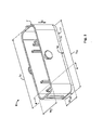
- Fig. 2
- shows a schematic perspective view of the housing of a braking module according an embodiment of the present invention;
- Fig. 3
- is a schematic perspective view of a connector of a braking module according to a first embodiment of the present invention;
- Fig. 4
- is a schematic cross-sectional view of a braking module according to a first embodi-ment of the present invention comprising a housing of
Fig. 2 and the mounted connec-tor ofFig. 3 , shown at the cross-sectional line 4-4; and - Fig. 5
- is a schematic cross-sectional view of another embodiment of the braking module ac-cording to the present invention, shown at a cross-sectional line corresponding to the one of
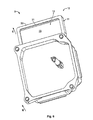
Fig. 4 ; - Fig. 6
- is a schematic perspective view of a housing of a braking module according to further embodiment of the present invention;
- Fig. 7
- is a schematic perspective view of a connector for the housing shown in
Fig. 6 ; - Fig. 8
- is a schematic perspective view of a braking module comprising the housing of
Fig. 6 and the connector ofFig. 7 ; and - Fig. 9
- is a cross-sectional view of the braking module according to the embodiment shown in
Fig, 8 , shown at the cross-sectional line 9-9. -
Fig. 1 shows a schematic perspective representation of a known braking module 1, namely acoil box module 2 of an electronic control unit of an anti-locking brake system (ABS). - The
coil box 2 comprises ahousing 3 for receiving the coils (not shown) that activate the valves in the hydraulic control unit (not shown) of the braking system (not shown). Thecoil box housing 3 is provided with aflange 4 for mounting thehousing 3 with the hydraulic control unit, thus forming an electronic hydraulic control unit that is mounted in the vehicle. Theflange 4 is provided at each of the four corners withbushing holes 5. When mounting thecoil box 2 in a mounting direction M with the hydraulic control unit, attachment elements (not shown) are inserted in the mounting direction M through thebushing holes 5 for fastening the braking module 1 of the present invention with the hydraulic control unit of the braking system. - The braking module 1 further comprises a
connector 6. Theconnector 6 comprises aconnector body 7 andcontact elements 8, herecontact pins 8a, definingconnector interfaces connector interface 9 is facing in the mounting direction M and is designed for being connected with a counter-connector of the cable assembly after the electronic hydraulic control unit is mounted in the vehicle. Theinterface 9a is facing in the direction opposite the mounting direction M and is designed for the connection with a printed circuit-board (not shown) of the electronic control system. - The
coil boxes 2 known from the prior art are designed as one integral piece in a molding process, which is complex and expensive because a very sophisticated housing mold is required for each connector-variant of one type of housing. Further the different shapes of the multiple connector-interfaces 9 and the number ofconnector contacts 8 thereof have a big influence on the mold flow and consequently the warpage in the complete braking module 1 mold. - In the following, the advantages of the braking module 1 according to the present invention is described with reference to the embodiment shown in
Figs. 2 to 9 . - As shown in the schematic perspective views of
Figs. 2 and3 , the braking module 1 of the present invention differs from thecoil box 2 of the prior art by its modular design in that the housing 3 (Fig. 2 ) is produced separately from the connector 6 (Fig. 3 ). - The
coil box housing 3 of the braking module 1 according to the present invention is principally designed similar to thecoil box housing 3 of the braking module 1 known from the prior art. - Thus, in the following the same reference signs will be used for elements that structurally and/or functionally are similar or identical to elements of
Fig. 1 . - The braking module 1 according to the present invention comprises a
housing 3 that is provided with ananchorage organ 10 for mounting theconnector 6 to the housing. In the shown embodiment, theanchorage organ 10 is designed as anattachment frame 11 arranged at the outside of one of thesidewalls 12 of thecoil box housing 3. In the shown embodiment, theside wall 12, where theattachment frame 11 is arranged, faces substantially perpendicular to the mounting direction M, in which the braking module 1 is mounted with the hydraulic control system. Theanchorage organ 10 may of course be arranged at any position of thehousing 3, provides that theconnector 3 may be mounted on theanchorage organ 10. - The
attachment frame 11 comprises a fitting 13 for coupling aconnection piece 14 of theconnector body 7. The fitting 13 is designed, in the embodiment shown inFig. 2 , as aninsertion opening 15, in which theconnector body 7 of theconnector 6 is received at least with its connection piece orpart 14, when theconnector 6 is coupled with the fitting 13. In the shown embodiment ofFigs. 2 to 5 , theconnection piece 14 of theconnector 6 is inserted in a coupling direction C, that is opposite to the mounting direction M in theinsertion opening 15. Likewise, theconnector 6 could be coupled/inserted in the mounting direction M with the fitting 13, as shown in the embodiment ofFigs. 6 to 9 . - In the embodiment of the
connector 6 shown inFig. 3 , theconnection piece 14 is designed by agroove 16 at thecoupling face 17, directed in the coupling direction C at the bottom of theconnector 6. In the exemplary design of the embodiment shown inFig. 3 , the width W14 of theconnection portion 14 is smaller than the width W7 of theconnector housing 7, and the length L14 of theconnector body 6 is shorter than the length L7 of the remainder of theconnector body 7. - In
Fig. 4 , the braking module 1 of a first embodiment of the present invention, comprising thehousing 3 ofFig. 2 and theconnector 6 ofFig. 3 is shown in the fully assembled state in a cross-sectional view along the cross-section lines 4-4 inFigs. 2 and3 . For the sake of clarity, the contact pins 8a that constitute thecontact elements 8 of the connector, are omitted inFig. 4 . - In the fully assembled state shown in
Fig. 4 , theconnector 6 is mounted and fixed at theanchorage organ 10 of thehousing 3. Theconnector body 7 is dimensioned such that, in the assembled state, the mountingface 18 of theconnector body 7 facing in mounting direction M is arranged such that it is easily accessible and can be coupled with the corresponding contact connector of the cable assembly of the vehicle. In the shown embodiment, the mountingface 18 is substantially flush with the mountingface 19 of theflange 4 of thehousing 3. In an alternative design, however, the mountingface 18 of theconnector 6 can come lower or higher, in the mounting direction M, than the mountingface 19 of thehousing 3 or can be arranged laterally with respect to the mounting direction M as long as the connector interface of the mounted electronic hydraulic control unit is freely accessible for coupling with the plug connector of the cable assembly. - The
connection piece 14 of theconnector body 7 is placed inside theinsertion hole 15 of the fitting 13. In the shown embodiment ofFig. 4 , thefitting area 20 of theattachment frame 11 encompassing theinsertion hole 15 in the direction perpendicular to the mounting direction M is provided with asupport lug 21, at its inside facing into theinsertion hole 15. In the shown embodiment, thesupport lug 21 circumferences theinsertion hole 15 completely and provide astep 21 a in thefitting portion area 20. Thestep 21 a forms a supportingsurface 22 on which theconnection piece 14 may rest in the assembled state, - In the embodiment shown in
Fig. 4 , a sealingelement 23, designed as agasket 24 is placed on the supportingsurface 22 formed by thestep 21 a and thus at thejunction 28 between theanchorage organ 10 and theconnector body 6 mounted thereto. Thegasket 24 is sealing thejunction 28 between theanchorage organ 10 and theconnector body 7. - The
groove 16 at theconnection piece 14 of theconnector body 7 is, in the assembled state, engaging with theshoulder 25 surrounding theinsertion hole 15, thereby forming a positive fit between theconnection piece 14 and the fitting 13 in the coupling direction C and in the direction perpendicular to the coupling direction C. - For fixing the
connector body 6 with theattachment frame 11 of theanchorage organ 10, a joiningelement 26 is provided. In the shown embodiment, the joiningelement 26 is anadhesive glue 27 that is placed in and filling thejunction 28 between theconnection piece 14 of theconnector body 7 and thefitting area 20 of theattachment frame 11, Instead of theglue 27, aseam 27 could be provided at thejunction 28. - The braking module 1 of the present invention having a
connector 6 and ahousing 3 independently produced and then mounted and fixed together subsequently provides the advantage of a great versatility because only one mold for a type ofhousing 3 that is provided with ananchorage organ 10 for mounting aconnector 6 is necessary. This housing can be combined withdifferent connectors 6 so that it is not necessary to design a new housing mold if ancommon housing type 3 shall be produced with adifferent connector 6 having anotherconnector interface - Further, the housing mold is simplified because no care has to be taken on the specific design of the
connector 6 which improves the mold flow in the housing mold. The same applies to the connector mold which can be optimized, for example with respect to the injection point, and the contact pins 8 can be integrally formed in theconnector body 7. - The
junction 28 may be made watertight in the embodiment shown inFig. 4 by applying apotting compound 31 sealingjunction 28 at the outside facing in the mounting direction M, thereof. - In
Fig. 5 , a second embodiment of the inventive braking module 1 is presented. In the following only the differences between thehousing 3 and theconnector 6 of the braking module 1 of the first embodiment, shown inFigs. 2 to 4 , with respect to thehousing 3 and theconnector 6 of the braking module 1 of the second embodiment are explained. - The
housing 3 of the second embodiment shown inFig. 5 principally corresponds to thehousing 3 of the first embodiment. The only difference is that theinsertion opening 15 is wider in the second embodiment. - The
connector 6 of the second embodiment principally corresponds to theconnector 6 of the first embodiment, too. However, theconnection piece 14 of the second embodiment is designed as aflange connection 29 protruding from the outer sidewalls of theconnector body 7 in the second embodiment, instead of thegroove 16 of the first embodiment. - The
flange connection 29 is provided at its lateral sides with apitch 32 that corresponds to and engages with thestep 21a of thefitting area 20 of theattachment frame 11 when mounting theconnector 6 with theanchorage organ 10 forming a similar positive fit as the one between thegroove 16 and theshoulder 25 in the first embodiment. - In the second embodiment shown in
Fig. 5 , theconnector 6 is fixed with theanchorage organ 10 by means of joiningelements 26 designed aslatches 30, which are integrally formed at theattachment frame 11. Thelatches 30 are provided at acoupling face 31 of theattachment frame 11 facing in the mounting direction M. - The
latches 30 are deflected by theconnection flange 29 of theconnector body 7, when mounting theconnector 6 in the coupling direction C with theanchorage organ 10, as indicated by the arrows inFig. 5 . After theconnector 6 is correctly mounted with theanchorage organ 10, thelatches 30 spring back into their resting position, as shown inFig. 5 , in which theconnection flange 29 engages with thelatch 30, thereby securing theconnector 6 in the mounted position. - Thus, the
latch 30 of thehousing 3 and theconnector flange 29 of the connector, forming a counter-latch element, can be engaged with each other such that thelatch 30 abuts against aconnection flange 29 and prevents theconnector body 7 from being removed in the mounting direction M from theanchorage organ 10. This snap-fit connector 6 with theanchorage organ 10 of thehousing 3 by inserting theconnection piece 14 of theconnector 6 in the coupling direction C into theinsertion hole 15 of theanchorage organ 10. - In
Figs. 6 to 9 , a third embodiment of the inventive braking module 1 is presented.Fig. 6 shows thehousing 3 of the braking module 1 according to the third embodiment,Fig. 7 shows theconnector 6 of the braking module 1 according to the third embodiment,Fig. 8 shows a schematic perspective view of the braking system 1 according to the third embodiment in the assembled state andFig. 9 shows a cross-sectional view along the sectional line 9-9 ofFig. 8 - In the following, only the differences between the braking module 1 according to the third and the previous embodiments will be described. For elements that are structurally and/or functionally similar or identical to elements of the previous embodiments, the same reference signs will be used.
- The
housing 3 according to the third embodiment principally corresponds to thehousing 6 of the second embodiment having thewide insertion opening 15. - The
housing 3 of the third embodiment differs from thehousing 6 of the second embodiment only in that the supportinglug 21, which completely circumferences theinsertion hole 15, providing thefitting portion area 20, is arranged at themargin 33 of thefitting area 20 that faces in the mounting direction M. Hence, the supportinglug 21 of theattachment frame 11 is arranged at that end of thefitting area 20 surrounding theinsertion hole 15, which faces in the mounting direction M, rather than at the opposite end, as it is the case in the housing according to the previous embodiments, shown inFigs. 4 and5 for example. - The
connector 6 of the third embodiment principally, corresponds to theconnector 6 of the second embodiment having aflange connection 29 protruding from the outer side walls of theconnector body 7 as aconnection piece 14. The theflange connection 29 according to the third embodiment is not provided with thepitch 32 of the second embodiment. Rather, theflange connection 29 of the third embodiment is simply designed as a planar collar surrounding the connector body. - Contrary to the braking module 1 according to the first and second embodiments, the
connector 6 of the third embodiment is inserted in the mounting direction M into theinsertion opening 15 of theanchorage organ 10. Thus, the coupling direction C, in which theconnector 6 is mounted with theanchorage organ 10 of thehousing 3, principally corresponds to the mounting direction M, in which the braking module 1 is mounted with the cable assembly. - As can be seen in
Fig. 9 , in the assembled state, theconnection flange 29 of theconnector 6 abuts against the supportinglug 21 of theattachment frame 11 in the mounting direction M that corresponds to the coupling direction C. - At the
junction 28 between theconnection flange 29 and thefitting area 20 of theanchorage organ 10, aseam 27 is provided, that forms the joiningelement 26, fixing theconnector 6 with thehousing 3, as well as at the same time providing a sealingelement 22, by which thejunction 28 is made watertight. -
1 braking module 2 coilbox 3 Housing 4 Flange 5 Bushing hole 6 Connector 7 Connector body 8 Contact element 8a Contact pin 9, 9a Connector interface 10 Anchorage organ 11 Attachment frame 12 Side wall of housing 13 Fitting 14 Connection piece 15 Insertion hole 16 Groove 17 Coupling face of connection part 18 (Mounting) face of connector body 19 (Mounting) face of housing 20 Fitting area 21 Supporting lug 21a Step 22 Supporting surface 23 Sealing element 24 Gasket 25 Shoulder 26 Joining element 27 Glue / seam 28 Junction 29 Connection flange 30 Latch 31 Potting compound 32 Pitch 33 Margin of fitting area facing in M C Coupling direction M Mounting direction
Claims (11)
- Braking system module (1), such as an coilbox (2), comprising a housing (3) and a connector (6) with a connector body (7) and contact elements (8) defining a connection interface (9) for electrically connecting the braking module (1) with a plug connector, characterized in that the housing (3) comprises an anchorage organ (10) for mounting the connector (6) to the housing (3).
- Braking module (1) according to claim 1, wherein the connector (6) is mounted and optionally fixed at the anchorage organ (10) of the housing (3).
- Braking module (1) according to claim 1 or 2, wherein the anchorage organ (10) comprises a fitting (13) that is adapted for coupling with a connection piece (14) of the connector body (7).
- Braking module (1) according to any one of claims 1 to 3, comprising a joining element (26) for fixing the mounted connector body (7) with the anchorage organ (10).
- Braking module (1) according to claim 4, wherein the joining element (26) is selected from at least one of a seam (27), a glue, and a fastener.
- Braking module (1) according to claim 5, wherein the joining element (26) is a snap fit (29, 30).
- Braking module (1) according to any one of claims 4 to 6, wherein the joining element (26) is arranged at the anchorage organ (10) and/or the connection piece (14).
- Braking module (1) according to claim 7, wherein the anchorage organ (10) comprises a latch (30) forming a snap fit (29, 30) with the corresponding counter latch (29) of the connector body (7).
- Braking module (1) according to any one of claims 1 to 8, comprising a sealing element (23) for sealing a junction (28) between the anchorage organ (10) and the connector body (7) mounted thereto.
- Braking module (1) according to claim 9, wherein the sealing element (23) is selected from a washer, grommet, gasket (24), a seam (27) and a potting compound (31).
- Braking module (1) according to claim 9 or 10, wherein a sealing element (23) is placed at the junction (28) between the anchorage organ (10) and the connector body (7).
Priority Applications (8)
| Application Number | Priority Date | Filing Date | Title |
|---|---|---|---|
| EP11005395A EP2540588A1 (en) | 2011-07-01 | 2011-07-01 | Module for a braking system, such as a coil box module comprising a housing and a connector |
| BR112013033997A BR112013033997A2 (en) | 2011-07-01 | 2012-06-22 | module for a braking system, such as a coil housing module comprising a housing and a connector |
| RU2014103462/11A RU2014103462A (en) | 2011-07-01 | 2012-06-22 | BRAKE SYSTEM MODULE AS A COIL MODULE CONTAINING A CASE AND CONNECTOR |
| PCT/EP2012/062123 WO2013004521A2 (en) | 2011-07-01 | 2012-06-22 | Module for a braking system, such as a coil box module comprising a housing and a connector |
| JP2014517615A JP2014523615A (en) | 2011-07-01 | 2012-06-22 | Module for braking system such as coil module with housing and connector |
| KR1020147002842A KR20140047110A (en) | 2011-07-01 | 2012-06-22 | Module for a braking system, such as a coil box module comprising a housing and a connector |
| CN201280033035.4A CN103889796A (en) | 2011-07-01 | 2012-06-22 | Modules for brake systems such as coil box modules with housing and connectors |
| US14/127,966 US20140196946A1 (en) | 2011-07-01 | 2012-06-22 | Module for a braking system, such as a coil box module comprising a housing and a connector |
Applications Claiming Priority (1)
| Application Number | Priority Date | Filing Date | Title |
|---|---|---|---|
| EP11005395A EP2540588A1 (en) | 2011-07-01 | 2011-07-01 | Module for a braking system, such as a coil box module comprising a housing and a connector |
Publications (1)
| Publication Number | Publication Date |
|---|---|
| EP2540588A1 true EP2540588A1 (en) | 2013-01-02 |
Family
ID=46513716
Family Applications (1)
| Application Number | Title | Priority Date | Filing Date |
|---|---|---|---|
| EP11005395A Withdrawn EP2540588A1 (en) | 2011-07-01 | 2011-07-01 | Module for a braking system, such as a coil box module comprising a housing and a connector |
Country Status (8)
| Country | Link |
|---|---|
| US (1) | US20140196946A1 (en) |
| EP (1) | EP2540588A1 (en) |
| JP (1) | JP2014523615A (en) |
| KR (1) | KR20140047110A (en) |
| CN (1) | CN103889796A (en) |
| BR (1) | BR112013033997A2 (en) |
| RU (1) | RU2014103462A (en) |
| WO (1) | WO2013004521A2 (en) |
Cited By (1)
| Publication number | Priority date | Publication date | Assignee | Title |
|---|---|---|---|---|
| EP2961001A1 (en) * | 2014-06-25 | 2015-12-30 | Tyco Electronics AMP Korea Ltd. | Header assembly and connector for vehicle having the header assembly |
Families Citing this family (2)
| Publication number | Priority date | Publication date | Assignee | Title |
|---|---|---|---|---|
| DE102014007443A1 (en) * | 2014-05-21 | 2015-11-26 | Brose Fahrzeugteile Gmbh & Co. Kommanditgesellschaft, Hallstadt | Electrical assembly for a motor vehicle and method for mounting such an electrical assembly |
| JP7217790B1 (en) * | 2021-10-19 | 2023-02-03 | 三菱電機株式会社 | power converter |
Citations (9)
| Publication number | Priority date | Publication date | Assignee | Title |
|---|---|---|---|---|
| WO1989005746A1 (en) * | 1987-12-14 | 1989-06-29 | Alfred Teves Gmbh | Valve block aggregate |
| WO1989010286A1 (en) * | 1988-04-20 | 1989-11-02 | Alfred Teves Gmbh | Electrohydraulic pressure-control device |
| WO1992012878A1 (en) * | 1991-01-15 | 1992-08-06 | Alfred Teves Gmbh | Electrohydraulic pressure regulator |
| DE19529314A1 (en) * | 1994-08-09 | 1996-02-15 | Nisshin Spinning | Multiple hydraulic control valves for use in motor vehicle ABS or ASR system |
| WO1996013415A1 (en) * | 1994-10-28 | 1996-05-09 | Siemens Aktiengesellschaft | Valve control device |
| DE19833498A1 (en) * | 1997-07-25 | 1999-01-28 | Nisshin Spinning | Control valve for hydraulic brake |
| DE19916014A1 (en) * | 1998-04-09 | 1999-10-21 | Unisia Jecs Corp | Hydraulic modulator for a motor vehicle, e.g. for an antilock braking system or anti-slip control system |
| WO2001042691A2 (en) * | 1999-12-08 | 2001-06-14 | Robert Bosch Gmbh | Proportional valve that can be actuated electromagnetically |
| DE102005041240A1 (en) * | 2005-08-31 | 2007-03-08 | Tyco Electronics Belgium Ec N.V. | Solenoid valve control means |
Family Cites Families (11)
| Publication number | Priority date | Publication date | Assignee | Title |
|---|---|---|---|---|
| DE2530157A1 (en) * | 1975-07-05 | 1977-02-03 | Bosch Gmbh Robert | ELECTRONIC CONTROL UNIT |
| US4785532A (en) * | 1985-10-22 | 1988-11-22 | Amp Incorporated | Method of making electrical connector assembly for antiskid braking system |
| JPH09509383A (en) * | 1994-02-10 | 1997-09-22 | ルーカス・インダストリーズ・パブリック・リミテッド・カンパニー | Anti-lock brake device |
| US5766026A (en) * | 1994-10-07 | 1998-06-16 | The Whitaker Corporation | Electrical connector assembly with sealed and spring biased electrical component |
| JPH1126097A (en) * | 1997-06-20 | 1999-01-29 | Molex Inc | Socket to be installed in panel |
| CN1132281C (en) * | 1998-06-29 | 2003-12-24 | 莫列斯公司 | System for mounting electrical connector on panel |
| JP4149633B2 (en) * | 2000-03-21 | 2008-09-10 | 矢崎総業株式会社 | Case and connector assembly structure |
| US6302747B1 (en) * | 2000-05-02 | 2001-10-16 | Buehler Products, Inc. | Two-position (on-off) actuator with modular connector |
| DE10352768B4 (en) * | 2002-11-19 | 2008-07-10 | Sumitomo Wiring Systems, Ltd., Yokkaichi | Connector and connector assembly |
| JP2010003550A (en) * | 2008-06-20 | 2010-01-07 | Yazaki Corp | Connector |
| US8241051B2 (en) * | 2010-07-22 | 2012-08-14 | Tyco Electronics Corporation | System and method for sealing a connector |
-
2011
- 2011-07-01 EP EP11005395A patent/EP2540588A1/en not_active Withdrawn
-
2012
- 2012-06-22 BR BR112013033997A patent/BR112013033997A2/en not_active IP Right Cessation
- 2012-06-22 KR KR1020147002842A patent/KR20140047110A/en not_active Withdrawn
- 2012-06-22 JP JP2014517615A patent/JP2014523615A/en not_active Withdrawn
- 2012-06-22 US US14/127,966 patent/US20140196946A1/en not_active Abandoned
- 2012-06-22 CN CN201280033035.4A patent/CN103889796A/en active Pending
- 2012-06-22 WO PCT/EP2012/062123 patent/WO2013004521A2/en not_active Ceased
- 2012-06-22 RU RU2014103462/11A patent/RU2014103462A/en not_active Application Discontinuation
Patent Citations (9)
| Publication number | Priority date | Publication date | Assignee | Title |
|---|---|---|---|---|
| WO1989005746A1 (en) * | 1987-12-14 | 1989-06-29 | Alfred Teves Gmbh | Valve block aggregate |
| WO1989010286A1 (en) * | 1988-04-20 | 1989-11-02 | Alfred Teves Gmbh | Electrohydraulic pressure-control device |
| WO1992012878A1 (en) * | 1991-01-15 | 1992-08-06 | Alfred Teves Gmbh | Electrohydraulic pressure regulator |
| DE19529314A1 (en) * | 1994-08-09 | 1996-02-15 | Nisshin Spinning | Multiple hydraulic control valves for use in motor vehicle ABS or ASR system |
| WO1996013415A1 (en) * | 1994-10-28 | 1996-05-09 | Siemens Aktiengesellschaft | Valve control device |
| DE19833498A1 (en) * | 1997-07-25 | 1999-01-28 | Nisshin Spinning | Control valve for hydraulic brake |
| DE19916014A1 (en) * | 1998-04-09 | 1999-10-21 | Unisia Jecs Corp | Hydraulic modulator for a motor vehicle, e.g. for an antilock braking system or anti-slip control system |
| WO2001042691A2 (en) * | 1999-12-08 | 2001-06-14 | Robert Bosch Gmbh | Proportional valve that can be actuated electromagnetically |
| DE102005041240A1 (en) * | 2005-08-31 | 2007-03-08 | Tyco Electronics Belgium Ec N.V. | Solenoid valve control means |
Cited By (1)
| Publication number | Priority date | Publication date | Assignee | Title |
|---|---|---|---|---|
| EP2961001A1 (en) * | 2014-06-25 | 2015-12-30 | Tyco Electronics AMP Korea Ltd. | Header assembly and connector for vehicle having the header assembly |
Also Published As
| Publication number | Publication date |
|---|---|
| RU2014103462A (en) | 2015-08-10 |
| CN103889796A (en) | 2014-06-25 |
| US20140196946A1 (en) | 2014-07-17 |
| BR112013033997A2 (en) | 2017-02-07 |
| WO2013004521A2 (en) | 2013-01-10 |
| JP2014523615A (en) | 2014-09-11 |
| WO2013004521A3 (en) | 2013-06-27 |
| KR20140047110A (en) | 2014-04-21 |
Similar Documents
| Publication | Publication Date | Title |
|---|---|---|
| CN101834381B (en) | Sealed and grounded electrical connector and assembly thereof | |
| US10199764B2 (en) | Waterproof electrical connector having a shielding shell with a stepped and recessed structure | |
| CN104806126B (en) | A kind of ready-package shower house fixes door mounting structure | |
| AU2010348146A1 (en) | Housing base element of a multi-part housing and method for assembly of a housing | |
| KR20100113545A (en) | Case for circuit board provided with electric connector, and electronic unit provided with the case | |
| US20140364012A1 (en) | Method for Producing a Control Unit Housing and Control Unit Housing Produced According to Said Method | |
| EP2540588A1 (en) | Module for a braking system, such as a coil box module comprising a housing and a connector | |
| US9605445B2 (en) | Component carrier for substantially electrical components | |
| US11193802B2 (en) | Sensor arrangement | |
| JP2013525995A (en) | Detachable plug connector | |
| CN107409468A (en) | electronic control unit | |
| CN110382314B (en) | Electric component assemblies and brake hydraulic control devices for vehicles | |
| EP4137373B1 (en) | Vehicle brake fluid pressure control device | |
| JPH09320694A (en) | Collective connector device | |
| US20130225002A1 (en) | Control unit for a vehicle and method for producing a control unit for a vehicle | |
| US10900817B2 (en) | Sensor system and method for producing a sensor system | |
| CN115336108A (en) | Terminal seat | |
| CN208169257U (en) | For the electronic control shell of lighting device to be assembled in package system and lighting device on the wall of lighting device | |
| CN109791059B (en) | Sensor device and method for manufacturing the sensor device | |
| CN103515785B (en) | Setting element | |
| CN106143377B (en) | Electronic control assembly for a vehicle safety system and method for manufacturing the same | |
| CN111052513A (en) | Contact elements, plug connection units and controllers | |
| CN101867130A (en) | Harness connector with barb for automatic transmission | |
| KR20060050330A (en) | Gear motor and its assembly method | |
| CN214206125U (en) | Stitch anti-sticking device of sensor |
Legal Events
| Date | Code | Title | Description |
|---|---|---|---|
| PUAI | Public reference made under article 153(3) epc to a published international application that has entered the european phase |
Free format text: ORIGINAL CODE: 0009012 |
|
| AK | Designated contracting states |
Kind code of ref document: A1 Designated state(s): AL AT BE BG CH CY CZ DE DK EE ES FI FR GB GR HR HU IE IS IT LI LT LU LV MC MK MT NL NO PL PT RO RS SE SI SK SM TR |
|
| AX | Request for extension of the european patent |
Extension state: BA ME |
|
| 17P | Request for examination filed |
Effective date: 20130628 |
|
| RBV | Designated contracting states (corrected) |
Designated state(s): AL AT BE BG CH CY CZ DE DK EE ES FI FR GB GR HR HU IE IS IT LI LT LU LV MC MK MT NL NO PL PT RO RS SE SI SK SM TR |
|
| STAA | Information on the status of an ep patent application or granted ep patent |
Free format text: STATUS: THE APPLICATION IS DEEMED TO BE WITHDRAWN |
|
| 18D | Application deemed to be withdrawn |
Effective date: 20170201 |