EP2540475A2 - High frequency induction heating double steel belt press apparatus - Google Patents
High frequency induction heating double steel belt press apparatus Download PDFInfo
- Publication number
- EP2540475A2 EP2540475A2 EP11744921A EP11744921A EP2540475A2 EP 2540475 A2 EP2540475 A2 EP 2540475A2 EP 11744921 A EP11744921 A EP 11744921A EP 11744921 A EP11744921 A EP 11744921A EP 2540475 A2 EP2540475 A2 EP 2540475A2
- Authority
- EP
- European Patent Office
- Prior art keywords
- induction coil
- steel belts
- glass fibers
- permeable steel
- high frequency
- Prior art date
- Legal status (The legal status is an assumption and is not a legal conclusion. Google has not performed a legal analysis and makes no representation as to the accuracy of the status listed.)
- Granted
Links
- 229910000831 Steel Inorganic materials 0.000 title claims abstract description 61
- 239000010959 steel Substances 0.000 title claims abstract description 61
- 230000006698 induction Effects 0.000 title claims abstract description 54
- 238000010438 heat treatment Methods 0.000 title claims abstract description 45
- 229920001169 thermoplastic Polymers 0.000 claims abstract description 30
- 239000004416 thermosoftening plastic Substances 0.000 claims abstract description 30
- 239000002131 composite material Substances 0.000 claims abstract description 12
- 238000004519 manufacturing process Methods 0.000 claims abstract description 5
- 239000003365 glass fiber Substances 0.000 claims description 23
- 238000001816 cooling Methods 0.000 claims description 19
- 238000005304 joining Methods 0.000 claims description 9
- 238000005470 impregnation Methods 0.000 claims description 8
- 239000000463 material Substances 0.000 claims description 8
- 239000010949 copper Substances 0.000 claims description 7
- RYGMFSIKBFXOCR-UHFFFAOYSA-N Copper Chemical compound [Cu] RYGMFSIKBFXOCR-UHFFFAOYSA-N 0.000 claims description 6
- 239000000498 cooling water Substances 0.000 claims description 6
- 229910052802 copper Inorganic materials 0.000 claims description 6
- 230000006835 compression Effects 0.000 claims description 5
- 238000007906 compression Methods 0.000 claims description 5
- 229910000975 Carbon steel Inorganic materials 0.000 claims description 4
- XAGFODPZIPBFFR-UHFFFAOYSA-N aluminium Chemical compound [Al] XAGFODPZIPBFFR-UHFFFAOYSA-N 0.000 claims description 4
- 229910052782 aluminium Inorganic materials 0.000 claims description 4
- 239000010962 carbon steel Substances 0.000 claims description 4
- 239000010935 stainless steel Substances 0.000 claims description 4
- 229910001220 stainless steel Inorganic materials 0.000 claims description 4
- 238000002844 melting Methods 0.000 claims description 2
- 230000008018 melting Effects 0.000 claims description 2
- 239000000088 plastic resin Substances 0.000 description 8
- 238000007731 hot pressing Methods 0.000 description 7
- 239000002990 reinforced plastic Substances 0.000 description 7
- 238000000034 method Methods 0.000 description 5
- 230000008569 process Effects 0.000 description 5
- 238000010586 diagram Methods 0.000 description 4
- 239000000835 fiber Substances 0.000 description 4
- 229920001431 Long-fiber-reinforced thermoplastic Polymers 0.000 description 3
- 238000009941 weaving Methods 0.000 description 3
- 230000000694 effects Effects 0.000 description 2
- 238000005265 energy consumption Methods 0.000 description 2
- 230000008439 repair process Effects 0.000 description 2
- 229920000049 Carbon (fiber) Polymers 0.000 description 1
- 230000004075 alteration Effects 0.000 description 1
- 238000013459 approach Methods 0.000 description 1
- 239000004917 carbon fiber Substances 0.000 description 1
- 230000008878 coupling Effects 0.000 description 1
- 238000010168 coupling process Methods 0.000 description 1
- 238000005859 coupling reaction Methods 0.000 description 1
- 230000007423 decrease Effects 0.000 description 1
- 230000002542 deteriorative effect Effects 0.000 description 1
- 239000011521 glass Substances 0.000 description 1
- 239000007788 liquid Substances 0.000 description 1
- 238000012986 modification Methods 0.000 description 1
- 230000004048 modification Effects 0.000 description 1
- 230000035515 penetration Effects 0.000 description 1
- 230000035699 permeability Effects 0.000 description 1
- 230000000704 physical effect Effects 0.000 description 1
- 239000004033 plastic Substances 0.000 description 1
- 229920003023 plastic Polymers 0.000 description 1
- 230000005855 radiation Effects 0.000 description 1
- 230000009467 reduction Effects 0.000 description 1
- 230000002787 reinforcement Effects 0.000 description 1
- 230000003014 reinforcing effect Effects 0.000 description 1
- 239000012783 reinforcing fiber Substances 0.000 description 1
- 239000011347 resin Substances 0.000 description 1
- 229920005989 resin Polymers 0.000 description 1
- 239000012815 thermoplastic material Substances 0.000 description 1
- 229920005992 thermoplastic resin Polymers 0.000 description 1
Images

Classifications
-
- H—ELECTRICITY
- H05—ELECTRIC TECHNIQUES NOT OTHERWISE PROVIDED FOR
- H05B—ELECTRIC HEATING; ELECTRIC LIGHT SOURCES NOT OTHERWISE PROVIDED FOR; CIRCUIT ARRANGEMENTS FOR ELECTRIC LIGHT SOURCES, IN GENERAL
- H05B6/00—Heating by electric, magnetic or electromagnetic fields
- H05B6/02—Induction heating
- H05B6/10—Induction heating apparatus, other than furnaces, for specific applications
- H05B6/105—Induction heating apparatus, other than furnaces, for specific applications using a susceptor
- H05B6/107—Induction heating apparatus, other than furnaces, for specific applications using a susceptor for continuous movement of material
-
- B—PERFORMING OPERATIONS; TRANSPORTING
- B29—WORKING OF PLASTICS; WORKING OF SUBSTANCES IN A PLASTIC STATE IN GENERAL
- B29C—SHAPING OR JOINING OF PLASTICS; SHAPING OF MATERIAL IN A PLASTIC STATE, NOT OTHERWISE PROVIDED FOR; AFTER-TREATMENT OF THE SHAPED PRODUCTS, e.g. REPAIRING
- B29C70/00—Shaping composites, i.e. plastics material comprising reinforcements, fillers or preformed parts, e.g. inserts
- B29C70/04—Shaping composites, i.e. plastics material comprising reinforcements, fillers or preformed parts, e.g. inserts comprising reinforcements only, e.g. self-reinforcing plastics
- B29C70/28—Shaping operations therefor
- B29C70/40—Shaping or impregnating by compression not applied
- B29C70/50—Shaping or impregnating by compression not applied for producing articles of indefinite length, e.g. prepregs, sheet moulding compounds [SMC] or cross moulding compounds [XMC]
- B29C70/504—Shaping or impregnating by compression not applied for producing articles of indefinite length, e.g. prepregs, sheet moulding compounds [SMC] or cross moulding compounds [XMC] using rollers or pressure bands
- B29C70/506—Shaping or impregnating by compression not applied for producing articles of indefinite length, e.g. prepregs, sheet moulding compounds [SMC] or cross moulding compounds [XMC] using rollers or pressure bands and impregnating by melting a solid material, e.g. sheet, powder, fibres
-
- B—PERFORMING OPERATIONS; TRANSPORTING
- B29—WORKING OF PLASTICS; WORKING OF SUBSTANCES IN A PLASTIC STATE IN GENERAL
- B29C—SHAPING OR JOINING OF PLASTICS; SHAPING OF MATERIAL IN A PLASTIC STATE, NOT OTHERWISE PROVIDED FOR; AFTER-TREATMENT OF THE SHAPED PRODUCTS, e.g. REPAIRING
- B29C43/00—Compression moulding, i.e. applying external pressure to flow the moulding material; Apparatus therefor
- B29C43/32—Component parts, details or accessories; Auxiliary operations
- B29C43/44—Compression means for making articles of indefinite length
- B29C43/48—Endless belts
- B29C2043/483—Endless belts cooperating with a second endless belt, i.e. double band presses
-
- B—PERFORMING OPERATIONS; TRANSPORTING
- B29—WORKING OF PLASTICS; WORKING OF SUBSTANCES IN A PLASTIC STATE IN GENERAL
- B29K—INDEXING SCHEME ASSOCIATED WITH SUBCLASSES B29B, B29C OR B29D, RELATING TO MOULDING MATERIALS OR TO MATERIALS FOR MOULDS, REINFORCEMENTS, FILLERS OR PREFORMED PARTS, e.g. INSERTS
- B29K2101/00—Use of unspecified macromolecular compounds as moulding material
- B29K2101/12—Thermoplastic materials
Definitions
- the present invention relates to an apparatus for manufacturing a thermoplastic/filament hybrid composite, and more particularly, to a high frequency induction heating double steel belt press apparatus, which employs an induction heating unit and a pair of steel belts to allow rapid heating through accurate and uniform temperature control.
- filament-reinforced plastics include continuous fibers for reinforcement such as glass fibers or carbon fibers embedded in plastics, which typically have relatively low mechanical strength.
- Such filament-reinforced plastics exhibit superior properties in terms of mechanical strength, rigidity and impact strength to short fiber-reinforced thermoplastics having a length of 1 mm or less or to long fiber-reinforced plastics such as long fiber-reinforced thermoplastics (LFT) or glass mat-reinforced thermoplastics (GMT), which have a length of 5 to 50 mm.
- LFT long fiber-reinforced thermoplastics
- GTT glass mat-reinforced thermoplastics
- filament-reinforced plastics need to have flexibility so as to be woven in a single or two directions such that the woven filament-reinforced plastic structure may be applied to products requiring various mechanical properties.
- the filament-reinforced plastics are typically produced through pultrusion or a process of commingling followed by hot pressing.
- pultrusion In pultrusion, widely dispersed bundles of filaments are passed through dies or a bath containing a liquid (or melt) resin so as to impregnate the plastic resin into the bundles of filaments.
- pultrusion can increase the degree of impregnation under optimal process conditions, it is difficult to regulate the amounts of the reinforcing fibers (that is, filaments) and the plastic resin, and to weave the filament-reinforced plastics due to low flexibility.
- filaments and a fiber plastic resin are commingled and then subjected to hot pressing. Since the filaments do not lose inherent flexibility of fibers even after physical coupling between the filaments and the plastic resin through commingling and hot pressing, the commingled filaments can be easily woven, exhibit excellent formability and impregnability upon hot pressing after weaving, and allow easy adjustment of the amounts of the reinforcing filament and the plastic resin in the filament-reinforced plastics.
- the present invention is directed to providing a high frequency induction heating double steel belt press apparatus for manufacturing a composite material through impregnation of glass fibers and a thermoplastic resin, which may reduce energy consumption during heating in a process of producing an impregnated thermoplastic hybrid composite tape through high frequency induction heating.
- the apparatus according to the present invention employs an openable high frequency induction heating coil unit, thereby facilitating replacement of the belts as needed and providing excellent workability in loading an initial sample on a belt press.
- the present invention is an apparatus for impregnating the thermoplastic tapes into both sides of the glass fibers provided in a band shape. For impregnation of the thermoplastic tapes into the glass fibers, heating, compression, and cooling are performed.
- Each of the permeable steel belts 110a, 110b is provided at opposite sides thereof with rollers, and the upper permeable steel belt 110a may be moved up or down. This configuration provides repair convenience together with loading convenience upon initially loading the glass fiber and the thermoplastic tapes.
- the cooling units 130a, 130b serve to cool the glass fibers and the thermoplastic tapes impregnated thereto downstream of the induction coil units 120a, 120b while hardening the glass fibers and the thermoplastic tapes through compression.
- the cooling units 130a, 130a are placed to apply force to compress upper and lower sides of the pair of permeable steel belts 110a, 110b while cooling the pair of permeable steel belts 110a, 110b.
- Such cooling units 130a, 130a may be embodied by press rollers through which cooling water flows. As the press rollers are maintained at low temperature by supplying the cooling water into the press rollers, it is possible to apply force to the permeable steel belts 110a, 110b, which contact the press rollers, while cooling the permeable steel belts 110a, 110b.
- the cooling units 130a, 130a are also configured to be lifted or lowered such that the distance between the pair of permeable steel belts 110a, 110b can be adjusted, as shown in Fig. 3 .
- the cooling units 130a, 130b are embodied by the press rollers through which cooling water flows, the press rollers are movable in the vertical direction.
- the apparatus employs high frequency induction heating in order to compensate for problems of conventional heating, such as eccentricity of steel belts caused by contact with multiple rollers in use of heating rollers, and heat loss in use of a radiation heat chamber, thereby enabling rapid heating through accurate and uniform temperature control while reducing power for heating the impregnated thermoplastic tapes and the glass fibers to 10% that of the state of the art without compromising heating performance.
Landscapes
- Chemical & Material Sciences (AREA)
- Engineering & Computer Science (AREA)
- Composite Materials (AREA)
- Mechanical Engineering (AREA)
- Physics & Mathematics (AREA)
- Electromagnetism (AREA)
- Moulding By Coating Moulds (AREA)
- Casting Or Compression Moulding Of Plastics Or The Like (AREA)
- Press Drives And Press Lines (AREA)
- General Induction Heating (AREA)
- Lining Or Joining Of Plastics Or The Like (AREA)
Abstract
Description
- The present invention relates to an apparatus for manufacturing a thermoplastic/filament hybrid composite, and more particularly, to a high frequency induction heating double steel belt press apparatus, which employs an induction heating unit and a pair of steel belts to allow rapid heating through accurate and uniform temperature control.
- Generally, filament-reinforced plastics include continuous fibers for reinforcement such as glass fibers or carbon fibers embedded in plastics, which typically have relatively low mechanical strength. Such filament-reinforced plastics exhibit superior properties in terms of mechanical strength, rigidity and impact strength to short fiber-reinforced thermoplastics having a length of 1 mm or less or to long fiber-reinforced plastics such as long fiber-reinforced thermoplastics (LFT) or glass mat-reinforced thermoplastics (GMT), which have a length of 5 to 50 mm.
- Further, filament-reinforced plastics need to have flexibility so as to be woven in a single or two directions such that the woven filament-reinforced plastic structure may be applied to products requiring various mechanical properties.
- The filament-reinforced plastics are typically produced through pultrusion or a process of commingling followed by hot pressing.
- In pultrusion, widely dispersed bundles of filaments are passed through dies or a bath containing a liquid (or melt) resin so as to impregnate the plastic resin into the bundles of filaments. Although pultrusion can increase the degree of impregnation under optimal process conditions, it is difficult to regulate the amounts of the reinforcing fibers (that is, filaments) and the plastic resin, and to weave the filament-reinforced plastics due to low flexibility.
- In the process of commingling followed by hot pressing, filaments and a fiber plastic resin are commingled and then subjected to hot pressing. Since the filaments do not lose inherent flexibility of fibers even after physical coupling between the filaments and the plastic resin through commingling and hot pressing, the commingled filaments can be easily woven, exhibit excellent formability and impregnability upon hot pressing after weaving, and allow easy adjustment of the amounts of the reinforcing filament and the plastic resin in the filament-reinforced plastics.
- In the process of commingling followed by hot pressing, however, since the plastic resin is randomly mingled with the bundle of filaments, the plastic resin is partially insufficiently impregnated into the bundle of filaments upon hot pressing after weaving, thereby deteriorating uniformity of physical properties. In addition, when the plastic resin is prepared in the form of fibers, there is a drawback in that only thermoplastic materials having sufficient elongation in relation with processibility can be restrictively used.
- Therefore, there is an urgent need for an apparatus for producing a thermoplastic/filament hybrid composite, which can be easily woven, exhibit excellent impregnation uniformity and impregnability upon melt impregnation after weaving, and allows application of various kinds of thermoplastics.
- The present invention is directed to providing a high frequency induction heating double steel belt press apparatus for manufacturing a composite material through impregnation of glass fibers and a thermoplastic resin, which may reduce energy consumption during heating in a process of producing an impregnated thermoplastic hybrid composite tape through high frequency induction heating.
- One aspect of the present invention provides a high frequency induction heating double steel belt press apparatus for manufacturing a thermoplastic/filament hybrid composite by supplying thermoplastic tapes to both sides of a widely dispersed bundle of glass fibers, followed by heating, compression, and cooling of the bundle of glass fibers, which includes a pair of permeable steel belts disposed above and under the glass fibers and the continuously supplied thermoplastic tapes, and rotated in opposite directions to transfer the glass fibers and the thermoplastic tapes while compressing the glass fibers and the thermoplastic tapes from above and down; inlet and outlet sprockets respectively provided to an inlet and an outlet of the pair of permeable steel belts to transfer the permeable steel belts; an induction coil unit divided into upper and lower plates to surround the permeable steel belts; and a cooling unit placed downstream of the induction coil unit and cooling a thermoplastics/filaments hybrid composite prepared through hot melting and impregnation in the induction coil unit while compressing upper and lower sides of the thermoplastic/filament hybrid composite. Here, the induction coil unit may be configured to allow the upper and lower plates to be opened or closed.
- The permeable steel belts may be made of at least one material selected from among aluminum, copper, stainless steel, and carbon steel.
- The induction coil unit may include joining points formed at opposite sides of each of the upper and lower plates such that the joining points can be connected to or disconnected from each other according to lifting or lowering operation of the permeable steel belts.
- The inlet sprocket or the outlet sprocket may be movable in a horizontal direction to adjust tension of the permeable steel belts.
- The glass fiber may be transferred at a speed of 2 to 40 m per minute, and electric current may be applied at a high frequency ranging from 20 to 40 Khz to the induction coil unit.
- The cooling unit may include a fan or a press roller through which cooling water flows, and the press roller may be movable in a vertical direction.
- In the apparatus according to the present invention, high frequency induction heating is used to heat impregnated thermoplastic tapes and glass fibers, thereby enabling rapid heating through accurate and uniform temperature control while reducing power for heating the impregnated thermoplastic tapes and the glass fibers to 10% that of the state of the art.
- In addition, the apparatus according to the present invention employs an openable high frequency induction heating coil unit, thereby facilitating replacement of the belts as needed and providing excellent workability in loading an initial sample on a belt press.
-
-
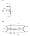
Fig. 1 is a diagram of a general high frequency induction heating system; and -
Fig. 2 andFig. 3 are diagrams of a high frequency induction heating double steel belt press apparatus according to one embodiment of the present invention. - Embodiments of the present invention will now be described in more detail with reference to the accompanying drawings.
- The above and other aspects, features, and advantages of the invention will become apparent from the detailed description of the following embodiments in conjunction with the accompanying drawings. It should be understood that the present invention is not limited to the following embodiments and may be embodied in different ways, and that the embodiments are given to provide complete disclosure of the invention and to provide a thorough understanding of the invention to those skilled in the art. The scope of the invention is defined only by the claims. Like components will be denoted by like reference numerals throughout the specification.
- In the drawings, the sizes and relative sizes of elements may be exaggerated for clarity. Further, it will be understood that when a certain element is referred to as being "present inside" or "connected to" another element, the certain element can adjoin the other element or can be separated from the other element. When the element is separated from the other element, it should be understood that an intervening element can also be present to secure or connect the certain element to the other elements even without a description thereof in the specification.
-
Fig. 1 is a diagram of a general high frequency induction heating system. - For high frequency induction heating, a
heating coil 10 is generally prepared using a copper tube, through which cooling water can flow, and is spirally wound around an electricallyconductive heating object 20. When high frequency electric current is applied to theheating coil 10 made of the copper tube, heat is generated by electric current induced in the electricallyconductive heating object 20. Theheating object 20 may be made of aluminum, copper, stainless steel, or carbon steel. Advantageously, any magnetically permeable material may be used for the heating object. - High frequency induction heating is based on principles of Joule heating and energy loss by magnetic hysteresis. Considering the surface effect by which the penetration depth decreases with increasing frequency, it is necessary to select suitable frequencies according to applications.
-
Fig. 2 andFig. 3 are diagrams of a high frequency induction heating double steel belt press apparatus according to one embodiment of the present invention, in whichFig. 2 shows an induction coil unit in a closed state andFig. 3 shows the induction coil unit in an open state. - Referring to
Fig. 2 , the high frequency induction heating double steel belt press apparatus 100 according to this embodiment includes a pair ofpermeable steel belts inlet sprockets outlet sprockets permeable steel belts permeable steel belts induction coil units permeable steel belts permeable steel belts cooling units induction coil units induction coil units - The present invention is an apparatus for impregnating the thermoplastic tapes into both sides of the glass fibers provided in a band shape. For impregnation of the thermoplastic tapes into the glass fibers, heating, compression, and cooling are performed.
- In particular, according to the present invention, heating is performed through high frequency induction heating in order to reduce energy consumption.
- Next, the respective components of the high frequency induction heating double steel belt press apparatus according to the embodiment will be described in detail.
- The apparatus includes the pair of
permeable steel belts permeable steel belts - The pair of permeable steel belts is composed of an upper
permeable steel belt 110a and a lowerpermeable steel belt 110b, which are rotated in opposite directions. The upperpermeable steel belt 110a is rotated in the counterclockwise direction, and the lowerpermeable steel belt 110b is rotated in the counterclockwise direction. The glass fibers and the thermoplastic tapes are supplied from the left side in the drawings and are then passed through a gap between the upper and lowerpermeable steel belts - The
permeable steel belts - Each of the
permeable steel belts permeable steel belt 110a may be moved up or down. This configuration provides repair convenience together with loading convenience upon initially loading the glass fiber and the thermoplastic tapes. - Height adjustment of the upper
permeable steel belt 110a may be achieved through adjustment of a distance between theinlet sprocket 112a and theoutlet sprocket 114a disposed at both sides thereof. When the distance between theinlet sprocket 112a and theoutlet sprocket 114a is increased, the upperpermeable steel belt 110a is lifted, as shown inFig. 3 . - Although only the distance between the
inlet sprocket 112a and theoutlet sprocket 114a is illustrated as being adjustable inFig. 3 , the distance between theinlet sprocket 112b and theoutlet sprocket 114b may also be adjusted. - Adjustment of the distance between the
inlet sprockets outlet sprockets permeable steel belts inlet sprockets outlet sprockets - Among the
inlet sprockets outlet sprockets outlet sprockets inlet sprockets outlet sprockets permeable steel belts - The
induction coil units permeable steel belts permeable steel belts induction coil units steel belts - If the frequency is lower than this range, heating is not sufficiently performed, thereby making it difficult to obtain sufficient bonding. If the frequency is higher than this range, there is a possibility of flexibility loss due to excessive impregnation.
- Further, if the conveying speed of the
permeable steel belts - Each of the induction coil units may be divided into an upper
induction coil plate 120a placed above the upperpermeable steel belt 110a and a lowerinduction coil plate 120b placed under the lowerpermeable steel belt 110b. Each of the upper and lowerinduction coil plates - As shown in
Fig. 2 , when the upperinduction coil plate 120a approaches the lowerinduction coil plate 120b, the joining points thereof are joined to each other, so that the upper and lowerinduction coil plates Fig. 3 , the joining points are separated from each other. - When the upper
induction coil plate 120a is joined to the lowerinduction coil plate 120b via the joining points, the joinedinduction coil plates permeable steel belts permeable steel belts induction coil plates - With the configuration wherein the
induction coil plates - The cooling
units induction coil units - Thus, the cooling
units permeable steel belts permeable steel belts Such cooling units permeable steel belts permeable steel belts - Further, as in the induction coil units, the cooling
units permeable steel belts Fig. 3 . Specifically, when the coolingunits - According to the embodiment of the invention, the apparatus employs high frequency induction heating in order to compensate for problems of conventional heating, such as eccentricity of steel belts caused by contact with multiple rollers in use of heating rollers, and heat loss in use of a radiation heat chamber, thereby enabling rapid heating through accurate and uniform temperature control while reducing power for heating the impregnated thermoplastic tapes and the glass fibers to 10% that of the state of the art without compromising heating performance.
- Although some exemplary embodiments have been described with reference to the accompanying drawings, the present invention may be embodied in many different ways and should not be construed as being limited to the embodiments set forth herein. It will be understood by those skilled in the art that various modifications, changes, alterations, and equivalent embodiments can be made without departing from the spirit and scope of the invention. Therefore, it should be appreciated that the foregoing embodiments are provided for illustrative purposes only and are not to be in any way construed as limiting the present invention.
Claims (7)
- A high frequency induction heating double steel belt press apparatus for manufacturing a thermoplastic/filament hybrid composite by supplying thermoplastic tapes to both sides of a widely dispersed bundle of glass fibers, followed by heating, compression, and cooling the bundle of glass fibers, comprising:a pair of permeable steel belts disposed above and under the glass fibers and the continuously supplied thermoplastic tapes, and rotated in opposite directions to transfer the glass fibers and the thermoplastic tapes while compressing the glass fibers and the thermoplastic tapes from above and down;inlet and outlet sprockets respectively provided to an inlet and an outlet of the pair of permeable steel belts to transfer the permeable steel belts;an induction coil unit divided into upper and lower plates to surround the permeable steel belts, the induction coil unit being configured to allow the upper and lower plates to be open or closed; anda cooling unit placed downstream of the induction coil unit and cooling a thermoplastics/filaments hybrid composite prepared through hot melting and impregnation in the induction coil unit while compressing upper and lower sides of the thermoplastic/filament hybrid composite.
- The apparatus of claim 1, wherein the induction coil unit comprises joining points formed at opposite sides of each of the upper and lower plates such that the joining points can be connected to or disconnected from each other according to lifting or lowering operation of the permeable steel belts.
- The apparatus of claim 1, wherein the inlet sprocket or the outlet sprocket is movable in a horizontal direction to adjust tension of the permeable steel belts.
- The apparatus of claim 1, wherein the glass fibers are transferred at a speed of 2 to 40 m per minute, and electric current is applied at a high frequency ranging from 20 to 40 Khz to the induction coil unit.
- The apparatus of claim 1, wherein the cooling unit comprises a press roller through which cooling water flows.
- The apparatus of claim 5, wherein the press roller is movable in a vertical direction.
- The apparatus of claim 1, wherein the permeable steel belts are made of at least one material selected from among aluminum, copper, stainless steel, and carbon steel.
Applications Claiming Priority (2)
| Application Number | Priority Date | Filing Date | Title |
|---|---|---|---|
| KR1020100015554A KR101293892B1 (en) | 2010-02-22 | 2010-02-22 | Apprarus of double steel belt press heated by high frequency induction method |
| PCT/KR2011/001101 WO2011102679A2 (en) | 2010-02-22 | 2011-02-18 | High frequency induction heating double steel belt press apparatus |
Publications (3)
| Publication Number | Publication Date |
|---|---|
| EP2540475A2 true EP2540475A2 (en) | 2013-01-02 |
| EP2540475A4 EP2540475A4 (en) | 2015-06-03 |
| EP2540475B1 EP2540475B1 (en) | 2018-05-02 |
Family
ID=44483491
Family Applications (1)
| Application Number | Title | Priority Date | Filing Date |
|---|---|---|---|
| EP11744921.5A Not-in-force EP2540475B1 (en) | 2010-02-22 | 2011-02-18 | High frequency induction heating double steel belt press apparatus |
Country Status (6)
| Country | Link |
|---|---|
| US (1) | US9210741B2 (en) |
| EP (1) | EP2540475B1 (en) |
| JP (1) | JP5528577B2 (en) |
| KR (1) | KR101293892B1 (en) |
| CN (1) | CN102753330B (en) |
| WO (1) | WO2011102679A2 (en) |
Cited By (1)
| Publication number | Priority date | Publication date | Assignee | Title |
|---|---|---|---|---|
| WO2020108704A1 (en) * | 2018-11-27 | 2020-06-04 | Azl Aachen Gmbh | Device for pressing flat material |
Families Citing this family (13)
| Publication number | Priority date | Publication date | Assignee | Title |
|---|---|---|---|---|
| CN103112234A (en) * | 2013-03-04 | 2013-05-22 | 苏州裕克施乐塑料制品有限公司 | Composite material sheet production method and dual-tensioning device of composite material sheet |
| WO2015012043A1 (en) * | 2013-07-22 | 2015-01-29 | 株式会社瑞光 | Sealing device and sealing method |
| CN103753806B (en) * | 2014-01-07 | 2015-12-09 | 肖青 | Claw twist-off cap pad erection unit and preparation method thereof |
| US10321524B2 (en) * | 2014-01-17 | 2019-06-11 | Nike, Inc. | Conveyance curing system |
| CN103921454B (en) * | 2014-04-22 | 2016-04-27 | 湖南大学 | A kind of homogeneous heating and high-temperature resistant composite material production system |
| KR101693593B1 (en) * | 2014-10-30 | 2017-01-09 | 한국생산기술연구원 | Apparatus for Producing Prepreg Using Heat Transfer Belt |
| SG10201502704VA (en) | 2015-04-07 | 2016-11-29 | Singnergy Corp Pte Ltd | Apparatus and method for improved evaporation drying |
| EP3638492B1 (en) * | 2017-06-14 | 2023-01-11 | PHP Fibers GmbH | Ribbon-shaped composite material |
| JP6334795B1 (en) * | 2017-09-05 | 2018-05-30 | プロセスシステム株式会社 | Double belt press device and induction heating press module |
| KR102162644B1 (en) * | 2018-11-08 | 2020-10-08 | 주식회사 남전산업 | Apparatus for manufacturing of self-reinforced composite and composite by using the same |
| KR102288668B1 (en) * | 2020-01-21 | 2021-08-11 | 주식회사 엠쓰리 | A apparatus of double steel belt press |
| JP2022053622A (en) * | 2020-09-25 | 2022-04-06 | 株式会社Ihi物流産業システム | Double belt press machine |
| DE102023118977B3 (en) | 2023-07-18 | 2024-11-07 | Azl Aachen Gmbh | Pressing device and method for the continuous impregnation of fiber-reinforced, thermoplastic flat semi-finished products |
Family Cites Families (20)
| Publication number | Priority date | Publication date | Assignee | Title |
|---|---|---|---|---|
| NL83740C (en) * | 1949-07-07 | |||
| DE833252C (en) * | 1950-01-31 | 1952-03-06 | Dynamit Nobel Ag | Device for the continuous treatment of foils or sheets made of plastics |
| GB745628A (en) * | 1951-11-26 | 1956-02-29 | John Lewis | Methods of manufacturing laminated belting |
| US4219524A (en) * | 1979-01-10 | 1980-08-26 | Owens-Corning Fiberglas Corporation | Method and apparatus for producing sheet molding compound |
| JPS60155428A (en) * | 1984-01-25 | 1985-08-15 | Nippon Petrochem Co Ltd | Manufacture of laminated sheet or laminated film |
| JPS61242799A (en) * | 1985-04-19 | 1986-10-29 | Mitsubishi Rayon Eng Kk | Double steel belt press machine |
| DE3717308A1 (en) | 1987-05-22 | 1988-12-15 | Held Kurt | DOUBLE BELT PRESS FOR THE CONTINUOUS PRODUCTION OF ENDLESS MATERIALS |
| FR2640544B1 (en) * | 1988-12-21 | 1991-06-28 | Combe Daniel | PROCESS FOR PRODUCING CONTINUOUS PANELS AND MACHINE FOR IMPLEMENTING SAME |
| US5075057A (en) * | 1991-01-08 | 1991-12-24 | Hoedl Herbert K | Manufacture of molded composite products from scrap plastics |
| JP3098839B2 (en) * | 1992-03-03 | 2000-10-16 | 三菱化学株式会社 | Continuous reinforcement molding method and apparatus for fiber reinforced thermoplastic resin sheet |
| CN1067939C (en) * | 1994-01-28 | 2001-07-04 | 伊索斯波特联合机械构件有限公司 | Process and device for producing glass fibre mat reinforced thermoplastic boards |
| JP2852184B2 (en) * | 1994-05-23 | 1999-01-27 | 太陽工業株式会社 | Thermoplastic resin film material welding machine |
| DE19718772B4 (en) * | 1997-05-03 | 2015-08-20 | Dieffenbacher GmbH Maschinen- und Anlagenbau | Process and plant for the production of wood-based panels |
| KR100306126B1 (en) * | 1999-04-06 | 2001-09-24 | 하재호 | Mold heating device by using high-frequency induction heat |
| KR200178062Y1 (en) * | 1999-11-19 | 2000-04-15 | 김한곤 | Method for adhering Polyethylene sheet to a steel board by high- frequency induction heating |
| JP4437893B2 (en) * | 2003-04-14 | 2010-03-24 | 三菱レイヨン・エンジニアリング株式会社 | Heating and pressing method of workpiece by double belt machine and the same belt machine |
| JP4211624B2 (en) * | 2004-02-10 | 2009-01-21 | 富士ゼロックス株式会社 | Plastic sheet manufacturing method and plastic sheet manufacturing apparatus |
| US7476284B2 (en) * | 2004-03-17 | 2009-01-13 | Gyrotron Technology, Inc. | Method and apparatus for laminating glass sheets |
| US7406288B2 (en) * | 2004-12-13 | 2008-07-29 | Canon Kabushiki Kaisha | Image heating apparatus including pads and belts forming a pressurized nip |
| JP4756967B2 (en) * | 2005-09-14 | 2011-08-24 | キヤノン株式会社 | Image heating device |
-
2010
- 2010-02-22 KR KR1020100015554A patent/KR101293892B1/en not_active Expired - Fee Related
-
2011
- 2011-02-18 JP JP2012551103A patent/JP5528577B2/en not_active Expired - Fee Related
- 2011-02-18 WO PCT/KR2011/001101 patent/WO2011102679A2/en not_active Ceased
- 2011-02-18 US US13/578,943 patent/US9210741B2/en not_active Expired - Fee Related
- 2011-02-18 EP EP11744921.5A patent/EP2540475B1/en not_active Not-in-force
- 2011-02-18 CN CN201180010457.5A patent/CN102753330B/en not_active Expired - Fee Related
Non-Patent Citations (1)
| Title |
|---|
| See references of WO2011102679A2 * |
Cited By (2)
| Publication number | Priority date | Publication date | Assignee | Title |
|---|---|---|---|---|
| WO2020108704A1 (en) * | 2018-11-27 | 2020-06-04 | Azl Aachen Gmbh | Device for pressing flat material |
| EP4105006A1 (en) * | 2018-11-27 | 2022-12-21 | AZL Aachen GmbH | Device for pressing flat material |
Also Published As
| Publication number | Publication date |
|---|---|
| CN102753330A (en) | 2012-10-24 |
| KR101293892B1 (en) | 2013-08-06 |
| EP2540475A4 (en) | 2015-06-03 |
| WO2011102679A3 (en) | 2012-01-12 |
| JP2013517970A (en) | 2013-05-20 |
| EP2540475B1 (en) | 2018-05-02 |
| US20120318461A1 (en) | 2012-12-20 |
| KR20110096225A (en) | 2011-08-30 |
| US9210741B2 (en) | 2015-12-08 |
| CN102753330B (en) | 2014-11-05 |
| JP5528577B2 (en) | 2014-06-25 |
| WO2011102679A2 (en) | 2011-08-25 |
Similar Documents
| Publication | Publication Date | Title |
|---|---|---|
| US9210741B2 (en) | High frequency induction heating double steel belt press apparatus | |
| US9370884B2 (en) | Resin molding apparatus and resin molding method | |
| JP3947560B2 (en) | Method for molding fiber reinforced thermoplastic composite material, intermediate thereof, and composite sheet | |
| CN101636258B (en) | Induction-assisted production method | |
| US7419373B2 (en) | Apparatus and method for induction lamination of electrically conductive fiber-reinforced composite materials | |
| US20100291342A1 (en) | Method of preparing thermoplastics-continuous fiber hybrid composite | |
| CN103507280B (en) | A kind of manufacturing method of resin impregnated fiber sheet composite material | |
| US20140175696A1 (en) | System and Method for Forming Fiber Reinforced Polymer Tape | |
| EP2664447B1 (en) | Apparatus for manufacturing a high-strength composite sheet having superior embeddability, and method for manufacturing a high-strength composite sheet using same | |
| JP2014105310A (en) | Method of manufacturing prepreg | |
| CN111619142A (en) | A production device and forming method of thermoplastic composite yarn pultruded sheet | |
| CN103210159A (en) | Sandwich structure welded by high-frequency induction heating, and method for manufacturing same | |
| CN111347681B (en) | Electromagnetic induction welding apparatus for joining composite materials and associated joining method | |
| JP2015166130A (en) | Method for producing fiber-reinforced plastic | |
| JP6334795B1 (en) | Double belt press device and induction heating press module | |
| US5336526A (en) | Primary processing of laminated thermoplastic sheets | |
| KR20150081423A (en) | Compliant layer for matched tool molding of uneven composite preforms | |
| CN107283861B (en) | A kind of unilateral conductivity fibrous thermoplastic enhances the preparation process of band | |
| JP2518554B2 (en) | Method for producing molded article of thermoplastic polymer-based composite material reinforced with carbon fiber | |
| CN103921454B (en) | A kind of homogeneous heating and high-temperature resistant composite material production system | |
| JP2024139873A (en) | Automatic lamination device and method for manufacturing thermoplastic resin composite sheet | |
| JP2011202095A (en) | Apparatus and method for manufacturing prepreg | |
| CN206383332U (en) | A kind of prepreg equipment complex | |
| KR20240107210A (en) | Method of Molding Polymer Composites Using Induction Heating Form | |
| KR102288668B1 (en) | A apparatus of double steel belt press |
Legal Events
| Date | Code | Title | Description |
|---|---|---|---|
| PUAI | Public reference made under article 153(3) epc to a published international application that has entered the european phase |
Free format text: ORIGINAL CODE: 0009012 |
|
| 17P | Request for examination filed |
Effective date: 20120810 |
|
| AK | Designated contracting states |
Kind code of ref document: A2 Designated state(s): AL AT BE BG CH CY CZ DE DK EE ES FI FR GB GR HR HU IE IS IT LI LT LU LV MC MK MT NL NO PL PT RO RS SE SI SK SM TR |
|
| RIN1 | Information on inventor provided before grant (corrected) |
Inventor name: KIM, HEE-JUNE Inventor name: JUNG, GI-HOON |
|
| DAX | Request for extension of the european patent (deleted) | ||
| A4 | Supplementary search report drawn up and despatched |
Effective date: 20150508 |
|
| RIC1 | Information provided on ipc code assigned before grant |
Ipc: B29C 65/20 20060101ALI20150430BHEP Ipc: B29C 65/04 20060101AFI20150430BHEP |
|
| GRAP | Despatch of communication of intention to grant a patent |
Free format text: ORIGINAL CODE: EPIDOSNIGR1 |
|
| STAA | Information on the status of an ep patent application or granted ep patent |
Free format text: STATUS: GRANT OF PATENT IS INTENDED |
|
| INTG | Intention to grant announced |
Effective date: 20171208 |
|
| GRAS | Grant fee paid |
Free format text: ORIGINAL CODE: EPIDOSNIGR3 |
|
| GRAA | (expected) grant |
Free format text: ORIGINAL CODE: 0009210 |
|
| STAA | Information on the status of an ep patent application or granted ep patent |
Free format text: STATUS: THE PATENT HAS BEEN GRANTED |
|
| AK | Designated contracting states |
Kind code of ref document: B1 Designated state(s): AL AT BE BG CH CY CZ DE DK EE ES FI FR GB GR HR HU IE IS IT LI LT LU LV MC MK MT NL NO PL PT RO RS SE SI SK SM TR |
|
| REG | Reference to a national code |
Ref country code: GB Ref legal event code: FG4D |
|
| REG | Reference to a national code |
Ref country code: CH Ref legal event code: EP Ref country code: AT Ref legal event code: REF Ref document number: 994733 Country of ref document: AT Kind code of ref document: T Effective date: 20180515 |
|
| REG | Reference to a national code |
Ref country code: DE Ref legal event code: R096 Ref document number: 602011048032 Country of ref document: DE Ref country code: IE Ref legal event code: FG4D |
|
| REG | Reference to a national code |
Ref country code: SE Ref legal event code: TRGR |
|
| REG | Reference to a national code |
Ref country code: NL Ref legal event code: MP Effective date: 20180502 |
|
| REG | Reference to a national code |
Ref country code: LT Ref legal event code: MG4D |
|
| PG25 | Lapsed in a contracting state [announced via postgrant information from national office to epo] |
Ref country code: BG Free format text: LAPSE BECAUSE OF FAILURE TO SUBMIT A TRANSLATION OF THE DESCRIPTION OR TO PAY THE FEE WITHIN THE PRESCRIBED TIME-LIMIT Effective date: 20180802 Ref country code: NO Free format text: LAPSE BECAUSE OF FAILURE TO SUBMIT A TRANSLATION OF THE DESCRIPTION OR TO PAY THE FEE WITHIN THE PRESCRIBED TIME-LIMIT Effective date: 20180802 Ref country code: FI Free format text: LAPSE BECAUSE OF FAILURE TO SUBMIT A TRANSLATION OF THE DESCRIPTION OR TO PAY THE FEE WITHIN THE PRESCRIBED TIME-LIMIT Effective date: 20180502 Ref country code: LT Free format text: LAPSE BECAUSE OF FAILURE TO SUBMIT A TRANSLATION OF THE DESCRIPTION OR TO PAY THE FEE WITHIN THE PRESCRIBED TIME-LIMIT Effective date: 20180502 Ref country code: ES Free format text: LAPSE BECAUSE OF FAILURE TO SUBMIT A TRANSLATION OF THE DESCRIPTION OR TO PAY THE FEE WITHIN THE PRESCRIBED TIME-LIMIT Effective date: 20180502 |
|
| PG25 | Lapsed in a contracting state [announced via postgrant information from national office to epo] |
Ref country code: HR Free format text: LAPSE BECAUSE OF FAILURE TO SUBMIT A TRANSLATION OF THE DESCRIPTION OR TO PAY THE FEE WITHIN THE PRESCRIBED TIME-LIMIT Effective date: 20180502 Ref country code: GR Free format text: LAPSE BECAUSE OF FAILURE TO SUBMIT A TRANSLATION OF THE DESCRIPTION OR TO PAY THE FEE WITHIN THE PRESCRIBED TIME-LIMIT Effective date: 20180803 Ref country code: NL Free format text: LAPSE BECAUSE OF FAILURE TO SUBMIT A TRANSLATION OF THE DESCRIPTION OR TO PAY THE FEE WITHIN THE PRESCRIBED TIME-LIMIT Effective date: 20180502 Ref country code: LV Free format text: LAPSE BECAUSE OF FAILURE TO SUBMIT A TRANSLATION OF THE DESCRIPTION OR TO PAY THE FEE WITHIN THE PRESCRIBED TIME-LIMIT Effective date: 20180502 Ref country code: RS Free format text: LAPSE BECAUSE OF FAILURE TO SUBMIT A TRANSLATION OF THE DESCRIPTION OR TO PAY THE FEE WITHIN THE PRESCRIBED TIME-LIMIT Effective date: 20180502 |
|
| REG | Reference to a national code |
Ref country code: AT Ref legal event code: MK05 Ref document number: 994733 Country of ref document: AT Kind code of ref document: T Effective date: 20180502 |
|
| PG25 | Lapsed in a contracting state [announced via postgrant information from national office to epo] |
Ref country code: PT Free format text: LAPSE BECAUSE OF FAILURE TO SUBMIT A TRANSLATION OF THE DESCRIPTION OR TO PAY THE FEE WITHIN THE PRESCRIBED TIME-LIMIT Effective date: 20180903 |
|
| PG25 | Lapsed in a contracting state [announced via postgrant information from national office to epo] |
Ref country code: SK Free format text: LAPSE BECAUSE OF FAILURE TO SUBMIT A TRANSLATION OF THE DESCRIPTION OR TO PAY THE FEE WITHIN THE PRESCRIBED TIME-LIMIT Effective date: 20180502 Ref country code: RO Free format text: LAPSE BECAUSE OF FAILURE TO SUBMIT A TRANSLATION OF THE DESCRIPTION OR TO PAY THE FEE WITHIN THE PRESCRIBED TIME-LIMIT Effective date: 20180502 Ref country code: CZ Free format text: LAPSE BECAUSE OF FAILURE TO SUBMIT A TRANSLATION OF THE DESCRIPTION OR TO PAY THE FEE WITHIN THE PRESCRIBED TIME-LIMIT Effective date: 20180502 Ref country code: EE Free format text: LAPSE BECAUSE OF FAILURE TO SUBMIT A TRANSLATION OF THE DESCRIPTION OR TO PAY THE FEE WITHIN THE PRESCRIBED TIME-LIMIT Effective date: 20180502 Ref country code: AT Free format text: LAPSE BECAUSE OF FAILURE TO SUBMIT A TRANSLATION OF THE DESCRIPTION OR TO PAY THE FEE WITHIN THE PRESCRIBED TIME-LIMIT Effective date: 20180502 Ref country code: DK Free format text: LAPSE BECAUSE OF FAILURE TO SUBMIT A TRANSLATION OF THE DESCRIPTION OR TO PAY THE FEE WITHIN THE PRESCRIBED TIME-LIMIT Effective date: 20180502 Ref country code: PL Free format text: LAPSE BECAUSE OF FAILURE TO SUBMIT A TRANSLATION OF THE DESCRIPTION OR TO PAY THE FEE WITHIN THE PRESCRIBED TIME-LIMIT Effective date: 20180502 |
|
| REG | Reference to a national code |
Ref country code: DE Ref legal event code: R097 Ref document number: 602011048032 Country of ref document: DE |
|
| PG25 | Lapsed in a contracting state [announced via postgrant information from national office to epo] |
Ref country code: SM Free format text: LAPSE BECAUSE OF FAILURE TO SUBMIT A TRANSLATION OF THE DESCRIPTION OR TO PAY THE FEE WITHIN THE PRESCRIBED TIME-LIMIT Effective date: 20180502 Ref country code: IT Free format text: LAPSE BECAUSE OF FAILURE TO SUBMIT A TRANSLATION OF THE DESCRIPTION OR TO PAY THE FEE WITHIN THE PRESCRIBED TIME-LIMIT Effective date: 20180502 |
|
| PLBE | No opposition filed within time limit |
Free format text: ORIGINAL CODE: 0009261 |
|
| STAA | Information on the status of an ep patent application or granted ep patent |
Free format text: STATUS: NO OPPOSITION FILED WITHIN TIME LIMIT |
|
| 26N | No opposition filed |
Effective date: 20190205 |
|
| PG25 | Lapsed in a contracting state [announced via postgrant information from national office to epo] |
Ref country code: SI Free format text: LAPSE BECAUSE OF FAILURE TO SUBMIT A TRANSLATION OF THE DESCRIPTION OR TO PAY THE FEE WITHIN THE PRESCRIBED TIME-LIMIT Effective date: 20180502 |
|
| REG | Reference to a national code |
Ref country code: DE Ref legal event code: R119 Ref document number: 602011048032 Country of ref document: DE |
|
| REG | Reference to a national code |
Ref country code: CH Ref legal event code: PL |
|
| REG | Reference to a national code |
Ref country code: SE Ref legal event code: EUG |
|
| GBPC | Gb: european patent ceased through non-payment of renewal fee |
Effective date: 20190218 |
|
| PG25 | Lapsed in a contracting state [announced via postgrant information from national office to epo] |
Ref country code: LU Free format text: LAPSE BECAUSE OF NON-PAYMENT OF DUE FEES Effective date: 20190218 Ref country code: SE Free format text: LAPSE BECAUSE OF NON-PAYMENT OF DUE FEES Effective date: 20190219 Ref country code: MC Free format text: LAPSE BECAUSE OF FAILURE TO SUBMIT A TRANSLATION OF THE DESCRIPTION OR TO PAY THE FEE WITHIN THE PRESCRIBED TIME-LIMIT Effective date: 20180502 |
|
| REG | Reference to a national code |
Ref country code: BE Ref legal event code: MM Effective date: 20190228 |
|
| REG | Reference to a national code |
Ref country code: IE Ref legal event code: MM4A |
|
| PG25 | Lapsed in a contracting state [announced via postgrant information from national office to epo] |
Ref country code: AL Free format text: LAPSE BECAUSE OF FAILURE TO SUBMIT A TRANSLATION OF THE DESCRIPTION OR TO PAY THE FEE WITHIN THE PRESCRIBED TIME-LIMIT Effective date: 20180502 |
|
| PG25 | Lapsed in a contracting state [announced via postgrant information from national office to epo] |
Ref country code: LI Free format text: LAPSE BECAUSE OF NON-PAYMENT OF DUE FEES Effective date: 20190228 Ref country code: CH Free format text: LAPSE BECAUSE OF NON-PAYMENT OF DUE FEES Effective date: 20190228 |
|
| PG25 | Lapsed in a contracting state [announced via postgrant information from national office to epo] |
Ref country code: GB Free format text: LAPSE BECAUSE OF NON-PAYMENT OF DUE FEES Effective date: 20190218 Ref country code: IE Free format text: LAPSE BECAUSE OF NON-PAYMENT OF DUE FEES Effective date: 20190218 Ref country code: DE Free format text: LAPSE BECAUSE OF NON-PAYMENT OF DUE FEES Effective date: 20190903 |
|
| PG25 | Lapsed in a contracting state [announced via postgrant information from national office to epo] |
Ref country code: BE Free format text: LAPSE BECAUSE OF NON-PAYMENT OF DUE FEES Effective date: 20190228 Ref country code: FR Free format text: LAPSE BECAUSE OF NON-PAYMENT OF DUE FEES Effective date: 20190228 |
|
| PG25 | Lapsed in a contracting state [announced via postgrant information from national office to epo] |
Ref country code: TR Free format text: LAPSE BECAUSE OF FAILURE TO SUBMIT A TRANSLATION OF THE DESCRIPTION OR TO PAY THE FEE WITHIN THE PRESCRIBED TIME-LIMIT Effective date: 20180502 |
|
| PG25 | Lapsed in a contracting state [announced via postgrant information from national office to epo] |
Ref country code: MT Free format text: LAPSE BECAUSE OF NON-PAYMENT OF DUE FEES Effective date: 20190218 |
|
| PG25 | Lapsed in a contracting state [announced via postgrant information from national office to epo] |
Ref country code: CY Free format text: LAPSE BECAUSE OF FAILURE TO SUBMIT A TRANSLATION OF THE DESCRIPTION OR TO PAY THE FEE WITHIN THE PRESCRIBED TIME-LIMIT Effective date: 20180502 |
|
| PG25 | Lapsed in a contracting state [announced via postgrant information from national office to epo] |
Ref country code: IS Free format text: LAPSE BECAUSE OF FAILURE TO SUBMIT A TRANSLATION OF THE DESCRIPTION OR TO PAY THE FEE WITHIN THE PRESCRIBED TIME-LIMIT Effective date: 20180902 |
|
| PG25 | Lapsed in a contracting state [announced via postgrant information from national office to epo] |
Ref country code: HU Free format text: LAPSE BECAUSE OF FAILURE TO SUBMIT A TRANSLATION OF THE DESCRIPTION OR TO PAY THE FEE WITHIN THE PRESCRIBED TIME-LIMIT; INVALID AB INITIO Effective date: 20110218 |
|
| PG25 | Lapsed in a contracting state [announced via postgrant information from national office to epo] |
Ref country code: MK Free format text: LAPSE BECAUSE OF FAILURE TO SUBMIT A TRANSLATION OF THE DESCRIPTION OR TO PAY THE FEE WITHIN THE PRESCRIBED TIME-LIMIT Effective date: 20180502 |