EP2540372A2 - Filter Assembly for Use in a Baghouse - Google Patents
Filter Assembly for Use in a Baghouse Download PDFInfo
- Publication number
- EP2540372A2 EP2540372A2 EP12172927A EP12172927A EP2540372A2 EP 2540372 A2 EP2540372 A2 EP 2540372A2 EP 12172927 A EP12172927 A EP 12172927A EP 12172927 A EP12172927 A EP 12172927A EP 2540372 A2 EP2540372 A2 EP 2540372A2
- Authority
- EP
- European Patent Office
- Prior art keywords
- attachment portion
- flange
- tube sheet
- adapter ring
- accordance
- Prior art date
- Legal status (The legal status is an assumption and is not a legal conclusion. Google has not performed a legal analysis and makes no representation as to the accuracy of the status listed.)
- Withdrawn
Links
- 238000001914 filtration Methods 0.000 claims abstract description 29
- 238000000034 method Methods 0.000 claims description 21
- 230000008878 coupling Effects 0.000 claims description 13
- 238000010168 coupling process Methods 0.000 claims description 13
- 238000005859 coupling reaction Methods 0.000 claims description 13
- 238000003466 welding Methods 0.000 claims description 4
- 238000000465 moulding Methods 0.000 claims description 3
- 230000000712 assembly Effects 0.000 description 10
- 238000000429 assembly Methods 0.000 description 10
- 239000000463 material Substances 0.000 description 5
- -1 polypropylene Polymers 0.000 description 4
- 238000007789 sealing Methods 0.000 description 4
- 239000004743 Polypropylene Substances 0.000 description 3
- NIXOWILDQLNWCW-UHFFFAOYSA-N acrylic acid group Chemical group C(C=C)(=O)O NIXOWILDQLNWCW-UHFFFAOYSA-N 0.000 description 3
- 238000004891 communication Methods 0.000 description 3
- 229920000728 polyester Polymers 0.000 description 3
- 229920000069 polyphenylene sulfide Polymers 0.000 description 3
- 229920001155 polypropylene Polymers 0.000 description 3
- 239000004568 cement Substances 0.000 description 2
- 239000000428 dust Substances 0.000 description 2
- 239000011152 fibreglass Substances 0.000 description 2
- 239000012530 fluid Substances 0.000 description 2
- 229920002635 polyurethane Polymers 0.000 description 2
- 239000004814 polyurethane Substances 0.000 description 2
- 229920003051 synthetic elastomer Polymers 0.000 description 2
- 239000005061 synthetic rubber Substances 0.000 description 2
- REEBJQTUIJTGAL-UHFFFAOYSA-N 3-pyridin-1-ium-1-ylpropane-1-sulfonate Chemical compound [O-]S(=O)(=O)CCC[N+]1=CC=CC=C1 REEBJQTUIJTGAL-UHFFFAOYSA-N 0.000 description 1
- 235000008733 Citrus aurantifolia Nutrition 0.000 description 1
- JOYRKODLDBILNP-UHFFFAOYSA-N Ethyl urethane Chemical compound CCOC(N)=O JOYRKODLDBILNP-UHFFFAOYSA-N 0.000 description 1
- 229910000831 Steel Inorganic materials 0.000 description 1
- 235000011941 Tilia x europaea Nutrition 0.000 description 1
- 239000000853 adhesive Substances 0.000 description 1
- 230000001070 adhesive effect Effects 0.000 description 1
- 229910052782 aluminium Inorganic materials 0.000 description 1
- XAGFODPZIPBFFR-UHFFFAOYSA-N aluminium Chemical compound [Al] XAGFODPZIPBFFR-UHFFFAOYSA-N 0.000 description 1
- 239000010426 asphalt Substances 0.000 description 1
- 239000003245 coal Substances 0.000 description 1
- 230000007423 decrease Effects 0.000 description 1
- 239000010881 fly ash Substances 0.000 description 1
- 235000013305 food Nutrition 0.000 description 1
- 238000009434 installation Methods 0.000 description 1
- 239000004571 lime Substances 0.000 description 1
- 229910052751 metal Inorganic materials 0.000 description 1
- 239000002184 metal Substances 0.000 description 1
- 239000013618 particulate matter Substances 0.000 description 1
- 229920001084 poly(chloroprene) Polymers 0.000 description 1
- 229920001296 polysiloxane Polymers 0.000 description 1
- 239000007921 spray Substances 0.000 description 1
- 239000010959 steel Substances 0.000 description 1
- XLYOFNOQVPJJNP-UHFFFAOYSA-N water Substances O XLYOFNOQVPJJNP-UHFFFAOYSA-N 0.000 description 1
- 239000002023 wood Substances 0.000 description 1
Images

Classifications
-
- B—PERFORMING OPERATIONS; TRANSPORTING
- B01—PHYSICAL OR CHEMICAL PROCESSES OR APPARATUS IN GENERAL
- B01D—SEPARATION
- B01D46/00—Filters or filtering processes specially modified for separating dispersed particles from gases or vapours
- B01D46/02—Particle separators, e.g. dust precipitators, having hollow filters made of flexible material
-
- B—PERFORMING OPERATIONS; TRANSPORTING
- B01—PHYSICAL OR CHEMICAL PROCESSES OR APPARATUS IN GENERAL
- B01D—SEPARATION
- B01D46/00—Filters or filtering processes specially modified for separating dispersed particles from gases or vapours
- B01D46/0002—Casings; Housings; Frame constructions
- B01D46/0005—Mounting of filtering elements within casings, housings or frames
-
- B—PERFORMING OPERATIONS; TRANSPORTING
- B01—PHYSICAL OR CHEMICAL PROCESSES OR APPARATUS IN GENERAL
- B01D—SEPARATION
- B01D2265/00—Casings, housings or mounting for filters specially adapted for separating dispersed particles from gases or vapours
- B01D2265/02—Non-permanent measures for connecting different parts of the filter
- B01D2265/029—Special screwing connections, threaded sections
-
- B—PERFORMING OPERATIONS; TRANSPORTING
- B01—PHYSICAL OR CHEMICAL PROCESSES OR APPARATUS IN GENERAL
- B01D—SEPARATION
- B01D2271/00—Sealings for filters specially adapted for separating dispersed particles from gases or vapours
- B01D2271/02—Gaskets, sealings
- B01D2271/022—Axial sealings
-
- B—PERFORMING OPERATIONS; TRANSPORTING
- B01—PHYSICAL OR CHEMICAL PROCESSES OR APPARATUS IN GENERAL
- B01D—SEPARATION
- B01D2271/00—Sealings for filters specially adapted for separating dispersed particles from gases or vapours
- B01D2271/02—Gaskets, sealings
- B01D2271/027—Radial sealings
Definitions
- the field of the invention relates generally to filter assemblies for use in baghouses, and more particularly, to baghouses in industrial filtration applications.
- a filtration system in one aspect, includes a flexible attachment portion, the attachment portion configured to couple the bag filter to a tube sheet, an adapter ring attached to the attachment portion, and a bag filter attached to the adapter ring.
- attachment portion configured to couple a bag filter to a tube sheet.
- the attachment portion includes an adapter ring configured to couple the bag filter to the attachment ring.
- method for assembling a filtration system for use in an industrial air filtration unit includes molding an attachment portion, attaching an adapter ring to the attachment portion, and providing a bag filter.
- the method further includes coupling an attachment portion to the bag filter using an adapter ring, wherein the attachment portion includes a cavity defined by a first flange, and a second flange spaced a distance from the first flange, such that an annular slot is defined between the first and second flanges and coupling the attachment portion to a tube sheet within the industrial air filtration unit, such that the tube sheet is secured in the slot between the first and second flanges.
- FIG. 1 is a schematic illustration of an example filtration system 41 that is contained in air plenum or baghouse 40.
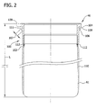
- FIG. 2 is an enlarged cross-sectional view of an example filter assembly 46 that may be used with filtration system 41.
- baghouse 40 includes a housing 42 that includes an inlet 44 and an outlet 48 that is downstream from inlet 44.
- a tube sheet 54 which extends across baghouse 40, divides baghouse 40 into a dirty air plenum 50 and a clean air plenum 52.
- dirty air and/or dirty gas are defined as particulate-containing air and/or gas
- clean air and/or clean air are defined as air and/or gas that has had substantially all particulate matter removed therefrom.
- tube sheet 54 is fabricated from a heat-resistive material, such as sheet metal, and includes at least a portion that is substantially planar.
- the planar portion of tube sheet 54 includes a plurality of apertures 56 defined therein.
- tube sheet 54 is positioned against the inner walls of the outer periphery of baghouse such that apertures 56 are the only locations within baghouse 40 that couple the dirty air plenum 50 and the clean air plenum in flow communication.
- apertures 56 are substantially evenly spaced across tube sheet 54.
- apertures 56 can have any spacing that allows baghouse 40 to function as described herein.
- Each filter assembly 46 is coupled to tube sheet 54 at a respective aperture 56. More specifically, each filter assembly 46 is coupled against tube sheet 54 such that each assembly 46 extends at least partially through a respective aperture 56. As such, in the example embodiment, each filter assembly 46 is positioned against both a dirty air side 57 and a clean air side 58 of tube sheet 54 as described in more detail below. Moreover, when fully assembled, dirty gas plenum 50 is substantially isolated and is substantially sealed from clean gas plenum 52 other than being in flow communication with plenum 50 via apertures 56. Although, filter assemblies 46 are illustrated as being vertically oriented, it should be noted that tube sheet 54 and filter assemblies 46 could be mounted in any relative orientation that enables baghouse 40 to function as described herein.
- each filter assembly 46 includes an attachment portion 100, which includes an adaptor ring 102 coupled to a bag filter 110. More specifically, in the example embodiment, bag filter 110 circumscribes attachment portion 100 and specifically, filter 110 circumscribes an outer periphery of adapter ring 102. In one embodiment, a cage is provided in the inner periphery of each bag filter 110 to provide support.
- Each bag filter 110 may be constructed of any material that enables a desired level of filtering to be satisfied based on the operating conditions of baghouse 40.
- filter 110 may be fabricated from materials such as, but not limited to polyester, polypropylene, PPS, acrylic, fiberglass.
- Attachment portion 100 includes a first tube sheet flange 104 and a second tube sheet flange 106.
- Flanges 104 and 106 are oriented such that a cavity 108 is defined between flanges 104 and 106. Cavity 108, as described in more detail below, is sized and shaped to receive tube sheet 54.
- First tube sheet flange 104 includes a substantially planar surface
- second tube sheet flange 106 includes a substantially tapered surface 107. Tapered surface 107 facilitates attachment portion 100 being inserted into tube sheet 54.
- Attachment portion 100 may be fabricated from any material that substantially prevents the ingress or egress of air or water, such as, but not limited to, polyurethane, silicone, neoprene, synthetic rubber made from polyurethane and is flexible to accommodate installation in tube sheet 54.
- adapter ring 102 is bonded to attachment portion 100 via a molding process in which adapter ring 102 is inserted in attachment portion 100. In such an embodiment, attachment portion 100 cures and adapter ring 102 is bonded internally with portion 100.
- adapter ring 102 is fabricated as part of a unitary mold with portion 100.
- adapter ring 102 is fabricated from materials that are substantially impervious to air and fluid, such as, but not limited to polyester, polypropylene, PPS, acrylic, urethane, synthetic rubber.
- bag filter 110 is coupled to adapter ring 102 by coupling filter 110 to flange 104 via a stitching process, wherein at least one stitch 112 is used.
- Any stitching hole size may be used to couple bag filter 110 to adapter ring 102 that enables attachment portion 100 to remain substantially impermeable to air and fluid.
- bag filter 110 and adapter ring 102 are sealed after stitches 112 are used to couple bag filter 110 to adapter ring 102.
- bag filter 110 is coupled to adapter ring 102 via a welding process, such as a sonic welding process.
- bag filter 110 is coupled to adapter ring 102 via an adhesive process.
- any other bonding technique can be sued to couple bag filter 110 to adapter ring 102.
- filter 110 is formed with a tubular configuration that has a substantially circular cross-sectional profile.
- filter media 61 may be formed in any shape or configuration that enables assemblies 46 to function as described herein.
- Filter assemblies 46 may be fabricated from any filter media that enables filter assembly 41 to function as described herein, including but not limited to, polyester, polypropylene, PPS, acrylic, fiberglass.
- filter assemblies 46 may be formed with any desired length L that enables the filtering requirements of baghouse 40 to be satisfied.
- tapered surface 107 of flange 106 facilitates attachment portion 100 being inserted into tube sheet 54 in a snap fit configuration.
- tube sheet 54 is seated in cavity 108 such that an outer periphery of each aperture 56 is in sealing contact with attachment portion 100.
- Cavity 108 is defined between a first tube sheet flange surface 109 and a second tube sheet flange surface 111.
- Tube sheet flange surfaces 109 and 111 are coupled to tube sheet 54 in a friction fit such that sealing contact is made between flange surface 109 and tube sheet 54, and between flange surface 111 and tube sheet 54.
- particulate-laden gas flow D enters inlet 44, and clean gas flow C is discharged through outlet 48 towards turbine engine inlet 30 (shown in FIG. 1 ). More specifically, particulate-laden flow D is filtered by assemblies 46 positioned within baghouse 40 and clean flow C exits through baghouse outlet 48. Dirty gas plenum 50 is substantially sealed from clean gas plenum 52 with filter assembly 46 such that flow communication therebetween is substantially prevented between dirty gas plenum 50 and clean gas plenum 52 except through assemblies 46.
- Tube sheet flanges 104 and 106 supports filter assembly 46 as the filter assembly 46 is suspended from tube sheet 54 as flow moves through filter assembly 46 during operation of baghouse 40.
- the above described methods and systems provide a cost effective filter assembly that can accommodate the aperture size variations found in baghouse tube sheets.
- the above described filter assemblies provide effective sealing of varying sized apertures within tube sheets, such that dust leakage around the filter bags is substantially prevented regardless of the size of the tube sheet apertures.
- the use of the above described filter assemblies also decreases the need to reject an entire set of bag filters that may be improperly sized to fit tube sheet apertures.
- Example embodiments of filter assembly for an industrial air filtration unit are described above in detail.
- the methods and systems are not limited to the specific embodiments described herein, but rather, components of systems and/or steps of the methods may be utilized independently and separately from other components and/or steps described herein.
- the methods may also be used in combination with other filtration systems and methods, and are not limited to practice with only the turbine systems and methods as described herein.
- example embodiment can be implemented and utilized in connection with many other filtration or sealing applications such as but not limited to cement kilns, cement transfer stations, asphalt plants, foundries, lime kilns, coal fired power plant baghouses, fly ash handling, bin vents, wood processing dust collectors, spray driers, aluminum ore processing, steel mills, and food processing plants.
Landscapes
- Chemical & Material Sciences (AREA)
- Chemical Kinetics & Catalysis (AREA)
- Filtering Of Dispersed Particles In Gases (AREA)
- Filtering Materials (AREA)
Abstract
A filtration system (41) is provided. The filtration system (41) includes a flexible attachment portion (100), the attachment portion configured to couple a bag filter (110) to a tube sheet (54), an adapter ring (102) attached to the attachment portion, and a bag filter (110) attached to the adapter ring (102).
Description
- The field of the invention relates generally to filter assemblies for use in baghouses, and more particularly, to baghouses in industrial filtration applications.
- In one aspect, a filtration system is provided. The filtration system includes a flexible attachment portion, the attachment portion configured to couple the bag filter to a tube sheet, an adapter ring attached to the attachment portion, and a bag filter attached to the adapter ring.
- In another aspect, attachment portion configured to couple a bag filter to a tube sheet is provided. The attachment portion includes an adapter ring configured to couple the bag filter to the attachment ring.
- In another aspect, method for assembling a filtration system for use in an industrial air filtration unit is provided. The method includes molding an attachment portion, attaching an adapter ring to the attachment portion, and providing a bag filter. The method further includes coupling an attachment portion to the bag filter using an adapter ring, wherein the attachment portion includes a cavity defined by a first flange, and a second flange spaced a distance from the first flange, such that an annular slot is defined between the first and second flanges and coupling the attachment portion to a tube sheet within the industrial air filtration unit, such that the tube sheet is secured in the slot between the first and second flanges.
-
-
FIG. 1 is a schematic illustration of an example filtration system that may be used with shown inFIG. 1 . -
FIG. 2 is an enlarged schematic illustration of an example filter assembly that may be used with the filtration system shown inFIG. 1 . -
Fig. 1 is a schematic illustration of anexample filtration system 41 that is contained in air plenum orbaghouse 40.FIG. 2 is an enlarged cross-sectional view of anexample filter assembly 46 that may be used withfiltration system 41. In the example embodiment,baghouse 40 includes ahousing 42 that includes aninlet 44 and anoutlet 48 that is downstream frominlet 44. Atube sheet 54, which extends acrossbaghouse 40, dividesbaghouse 40 into adirty air plenum 50 and aclean air plenum 52. As used herein, the terms "dirty air" and/or "dirty gas" are defined as particulate-containing air and/or gas, and the terms "clean air" and/or "clean air" are defined as air and/or gas that has had substantially all particulate matter removed therefrom. - In the example embodiment,
tube sheet 54 is fabricated from a heat-resistive material, such as sheet metal, and includes at least a portion that is substantially planar. The planar portion oftube sheet 54 includes a plurality ofapertures 56 defined therein. In the example embodiment,tube sheet 54 is positioned against the inner walls of the outer periphery of baghouse such thatapertures 56 are the only locations withinbaghouse 40 that couple thedirty air plenum 50 and the clean air plenum in flow communication. In the example embodiment,apertures 56 are substantially evenly spaced acrosstube sheet 54. Alternatively,apertures 56 can have any spacing that allowsbaghouse 40 to function as described herein. - Each
filter assembly 46 is coupled totube sheet 54 at arespective aperture 56. More specifically, eachfilter assembly 46 is coupled againsttube sheet 54 such that eachassembly 46 extends at least partially through arespective aperture 56. As such, in the example embodiment, eachfilter assembly 46 is positioned against both adirty air side 57 and aclean air side 58 oftube sheet 54 as described in more detail below. Moreover, when fully assembled,dirty gas plenum 50 is substantially isolated and is substantially sealed fromclean gas plenum 52 other than being in flow communication withplenum 50 viaapertures 56. Although,filter assemblies 46 are illustrated as being vertically oriented, it should be noted thattube sheet 54 andfilter assemblies 46 could be mounted in any relative orientation that enablesbaghouse 40 to function as described herein. - In the example embodiment, each
filter assembly 46 includes anattachment portion 100, which includes anadaptor ring 102 coupled to abag filter 110. More specifically, in the example embodiment,bag filter 110circumscribes attachment portion 100 and specifically,filter 110 circumscribes an outer periphery ofadapter ring 102. In one embodiment, a cage is provided in the inner periphery of eachbag filter 110 to provide support. Eachbag filter 110 may be constructed of any material that enables a desired level of filtering to be satisfied based on the operating conditions ofbaghouse 40. For example,filter 110 may be fabricated from materials such as, but not limited to polyester, polypropylene, PPS, acrylic, fiberglass. -
Attachment portion 100 includes a firsttube sheet flange 104 and a secondtube sheet flange 106.Flanges cavity 108 is defined betweenflanges Cavity 108, as described in more detail below, is sized and shaped to receivetube sheet 54. Firsttube sheet flange 104 includes a substantially planar surface, and secondtube sheet flange 106 includes a substantiallytapered surface 107. Taperedsurface 107 facilitatesattachment portion 100 being inserted intotube sheet 54.Attachment portion 100 may be fabricated from any material that substantially prevents the ingress or egress of air or water, such as, but not limited to, polyurethane, silicone, neoprene, synthetic rubber made from polyurethane and is flexible to accommodate installation intube sheet 54. - In the example embodiment,
adapter ring 102 is bonded toattachment portion 100 via a molding process in whichadapter ring 102 is inserted inattachment portion 100. In such an embodiment,attachment portion 100 cures andadapter ring 102 is bonded internally withportion 100. In an alternative embodiment,adapter ring 102 is fabricated as part of a unitary mold withportion 100. In the example embodiment,adapter ring 102 is fabricated from materials that are substantially impervious to air and fluid, such as, but not limited to polyester, polypropylene, PPS, acrylic, urethane, synthetic rubber. In the example embodiment,bag filter 110 is coupled toadapter ring 102 bycoupling filter 110 toflange 104 via a stitching process, wherein at least onestitch 112 is used. Any stitching hole size may be used to couplebag filter 110 toadapter ring 102 that enablesattachment portion 100 to remain substantially impermeable to air and fluid. In one embodiment,bag filter 110 andadapter ring 102 are sealed afterstitches 112 are used tocouple bag filter 110 toadapter ring 102. In an alternative embodiment,bag filter 110 is coupled toadapter ring 102 via a welding process, such as a sonic welding process. In another embodiment,bag filter 110 is coupled toadapter ring 102 via an adhesive process. Alternatively, any other bonding technique can be sued tocouple bag filter 110 toadapter ring 102. - In the example embodiment,
filter 110 is formed with a tubular configuration that has a substantially circular cross-sectional profile. Alternatively,filter media 61 may be formed in any shape or configuration that enablesassemblies 46 to function as described herein.Filter assemblies 46 may be fabricated from any filter media that enablesfilter assembly 41 to function as described herein, including but not limited to, polyester, polypropylene, PPS, acrylic, fiberglass. Moreover,filter assemblies 46 may be formed with any desired length L that enables the filtering requirements ofbaghouse 40 to be satisfied. - When
filter assembly 46 is inserted inbaghouse tube sheet 54,tapered surface 107 offlange 106 facilitatesattachment portion 100 being inserted intotube sheet 54 in a snap fit configuration. In the example embodiment,tube sheet 54 is seated incavity 108 such that an outer periphery of eachaperture 56 is in sealing contact withattachment portion 100.Cavity 108 is defined between a first tubesheet flange surface 109 and a second tubesheet flange surface 111. Tubesheet flange surfaces tube sheet 54 in a friction fit such that sealing contact is made betweenflange surface 109 andtube sheet 54, and betweenflange surface 111 andtube sheet 54. - During operation, particulate-laden gas flow D enters
inlet 44, and clean gas flow C is discharged throughoutlet 48 towards turbine engine inlet 30 (shown inFIG. 1 ). More specifically, particulate-laden flow D is filtered byassemblies 46 positioned withinbaghouse 40 and clean flow C exits throughbaghouse outlet 48.Dirty gas plenum 50 is substantially sealed fromclean gas plenum 52 withfilter assembly 46 such that flow communication therebetween is substantially prevented betweendirty gas plenum 50 andclean gas plenum 52 except throughassemblies 46.Tube sheet flanges filter assembly 46 as thefilter assembly 46 is suspended fromtube sheet 54 as flow moves throughfilter assembly 46 during operation ofbaghouse 40. - The above described methods and systems provide a cost effective filter assembly that can accommodate the aperture size variations found in baghouse tube sheets. The above described filter assemblies provide effective sealing of varying sized apertures within tube sheets, such that dust leakage around the filter bags is substantially prevented regardless of the size of the tube sheet apertures. The use of the above described filter assemblies also decreases the need to reject an entire set of bag filters that may be improperly sized to fit tube sheet apertures.
- Example embodiments of filter assembly for an industrial air filtration unit are described above in detail. The methods and systems are not limited to the specific embodiments described herein, but rather, components of systems and/or steps of the methods may be utilized independently and separately from other components and/or steps described herein. For example, the methods may also be used in combination with other filtration systems and methods, and are not limited to practice with only the turbine systems and methods as described herein. Rather, the example embodiment can be implemented and utilized in connection with many other filtration or sealing applications such as but not limited to cement kilns, cement transfer stations, asphalt plants, foundries, lime kilns, coal fired power plant baghouses, fly ash handling, bin vents, wood processing dust collectors, spray driers, aluminum ore processing, steel mills, and food processing plants.
- Although specific features of various embodiments of the invention may be shown in some drawings and not in others, this is for convenience only. In accordance with the principles of the invention, any feature of a drawing may be referenced and/or claimed in combination with any feature of any other drawing.
Claims (15)
- A filtration system (41) comprising:a flexible attachment portion (100), said attachment portion configured to couple a bag filter (110) to a tube sheet (54);an adapter ring (102) attached to said attachment portion; anda bag filter attached to said adapter ring (102).
- A filtration system (41) in accordance with Claim 1, wherein the tube sheet (54) is secured within an annular slot (108) defined between a first flange (104) and a second flange (106) extending from said attachment portion (100), and wherein said first flange extends radially outward across the tube sheet farther than said second flange.
- A filtration system (41) in accordance with Claim 2, wherein said second flange (106) is oriented to taper from the slot (108) towards a center of said attachment portion (100).
- A filtration system (41) in accordance with Claim 3, wherein said adapter ring (102) is molded to said attachment portion (100).
- A filtration system (41) in accordance with any one of Claims 1 to 4, wherein:said adapter ring (102) is bonded to said attachment portion (100); orsaid adapter ring (102) is integrally formed with said attachment portion (100);orsaid attachment portion (100) is coupled to said bag (110) using welding.
- An attachment portion (100) configured to couple a bag filter (110) to a tube sheet (54), said attachment portion comprising an adapter ring (102) configured to couple the bag filter to said attachment ring.
- An attachment portion (100) in accordance with Claim 6, further comprising:a first flange (104) extending from said attachment portion (100) and configured to couple against a first side of a tube sheet (54); anda second flange (106) extending from said attachment portion (100) and configured to couple against a second side of a tube sheet, said second flange spaced from said first flange such that an annular cavity (108) is defined therebetween, the tube sheet secured in said annular cavity, wherein said first flange extends radially outward across the tube sheet farther than said second flange.
- An attachment portion (100) in accordance with Claim 7, wherein said second flange (106) is oriented to taper from the cavity towards a center of said attachment portion.
- An attachment portion in accordance with Claim 7 or Claim 8, wherein said second flange further comprises a second flange configured to flex as said attachment portion is coupled to the tube sheet.
- An attachment portion in accordance with any one of Claims 6 to 9, wherein said adapter ring is bonded to said attachment ring; and/or
said adapter ring is integrally formed with said attachment ring. - A method for assembling a filtration system for use in an industrial air filtration unit, said method comprising:molding an attachment portion (100);attaching an adapter ring (102) to the attachment portion (100);providing a bag filter (110);coupling an attachment portion (100) to the bag filter (110) using an adapter ring (102), wherein the attachment portion (100) includes a cavity defined by a first flange, and a second flange spaced a distance from the first flange, such that an annular slot is defined between the first and second flanges; andcoupling the attachment portion (100) to a tube sheet (54) within the industrial air filtration unit, such that the tube sheet is secured in the slot between the first and second flanges.
- A method for assembling a filtration system in accordance with Claim 11, wherein coupling an attachment portion (100) to the tube sheet (54) further comprises coupling the attachment portion to the tube sheet such that a first flange extends radially outward across the tube sheet farther that the second flange.
- A method for assembling a filtration system in accordance with Claim 11 or Claim 12, wherein coupling an attachment portion (100) to the bag filter (110) further comprises coupling the attachment portion to the bag filter such that the second flange is oriented to taper from the cavity towards a center of the attachment portion, and preferably such that the second flange is configured to flex as the attachment portion (100) is coupled to the tube sheet (54).
- A method for assembling a filtration system in accordance with Claim 11, 12 or 13, wherein coupling an attachment portion to the tube sheet further comprises coupling the attachment portion (100) to the tube sheet (54) in a snap fit configuration, and preferably further comprising providing an attachment portion (100) that includes an adapter ring (102) integrally formed with the attachment portion (100).
- A method for assembling a filtration system in accordance with any one of Claims 11 to 14, wherein coupling an attachment portion (100) to the bag filter (54) further comprises coupling the attachment portion to the bag filter using at least one of welding and stitching.
Applications Claiming Priority (1)
| Application Number | Priority Date | Filing Date | Title |
|---|---|---|---|
| US13/169,816 US20120324845A1 (en) | 2011-06-27 | 2011-06-27 | Filter assembly for use in a baghouse |
Publications (1)
| Publication Number | Publication Date |
|---|---|
| EP2540372A2 true EP2540372A2 (en) | 2013-01-02 |
Family
ID=46982335
Family Applications (1)
| Application Number | Title | Priority Date | Filing Date |
|---|---|---|---|
| EP12172927A Withdrawn EP2540372A2 (en) | 2011-06-27 | 2012-06-21 | Filter Assembly for Use in a Baghouse |
Country Status (3)
| Country | Link |
|---|---|
| US (1) | US20120324845A1 (en) |
| EP (1) | EP2540372A2 (en) |
| CN (1) | CN102847384A (en) |
Families Citing this family (6)
| Publication number | Priority date | Publication date | Assignee | Title |
|---|---|---|---|---|
| US9061251B2 (en) * | 2011-09-27 | 2015-06-23 | Markel Corporation | Self sealing membrane contactor with PTFE tubular membranes |
| US9067164B2 (en) | 2012-05-17 | 2015-06-30 | Donaldson Company, Inc. | Filter systems with dirty air chamber spacer elements and methods of using the same |
| JP6585616B2 (en) * | 2014-03-21 | 2019-10-02 | ライフ テクノロジーズ コーポレイション | Gas filter system for fluid treatment system |
| CN105485064A (en) * | 2015-12-11 | 2016-04-13 | 成都瑞柯林工程技术有限公司 | Air compression system and air compression method |
| WO2018009480A1 (en) * | 2016-07-07 | 2018-01-11 | Bha Altair, Llc | Variable diameter top for a filter element |
| US11559757B2 (en) | 2020-03-02 | 2023-01-24 | Marclara, LLC | Water filtration apparatus |
Family Cites Families (7)
| Publication number | Priority date | Publication date | Assignee | Title |
|---|---|---|---|---|
| DK141433B (en) * | 1977-10-24 | 1980-03-17 | Nordisk Pladeroersfabrik As | Holder for filter bag. |
| CN1033163A (en) * | 1987-11-18 | 1989-05-31 | 南京工学院 | Bag-type whirlwind dust remover |
| US5308369A (en) * | 1993-04-28 | 1994-05-03 | Griffin Environmental Company, Inc. | Snap-in filter bag assembly for bottom loading in dust collector |
| CN2239285Y (en) * | 1995-06-30 | 1996-11-06 | 王炳暄 | Pleated bag type air filter |
| CN2302840Y (en) * | 1997-07-22 | 1999-01-06 | 郑龙和 | Shocking flat bag type filtering equipment |
| US7186284B2 (en) * | 2004-02-13 | 2007-03-06 | Bha Group, Inc. | Filter mounting system |
| DE102006007182A1 (en) * | 2006-02-15 | 2007-08-23 | Carl Freudenberg Kg | Filter element and arrangement |
-
2011
- 2011-06-27 US US13/169,816 patent/US20120324845A1/en not_active Abandoned
-
2012
- 2012-06-21 EP EP12172927A patent/EP2540372A2/en not_active Withdrawn
- 2012-06-27 CN CN2012102148273A patent/CN102847384A/en active Pending
Non-Patent Citations (1)
| Title |
|---|
| None |
Also Published As
| Publication number | Publication date |
|---|---|
| CN102847384A (en) | 2013-01-02 |
| US20120324845A1 (en) | 2012-12-27 |
Similar Documents
| Publication | Publication Date | Title |
|---|---|---|
| EP2540372A2 (en) | Filter Assembly for Use in a Baghouse | |
| US8540805B2 (en) | Filter assembly for use in a turbine system | |
| US10293294B2 (en) | Air filter system and air filter element for an air filter system | |
| US8580004B1 (en) | Unitary filter cartridge with flow transition mouth | |
| US8673043B2 (en) | Fluid filter | |
| US8147576B2 (en) | Filter element having serrated seal | |
| US20100275559A1 (en) | Filter Element Having V-Seal | |
| US7905935B2 (en) | Twist and lock connection for pleated filter element | |
| US20150082982A1 (en) | Filter Element and Filter System Having a Filter Element | |
| EP1307272B1 (en) | Filter assembly | |
| KR20100128299A (en) | Multiple bellows type filters with increased efficiency | |
| US20100101195A1 (en) | Twist and lock connection for pleated filter element with flange-to-flange locking means | |
| EP4252887A1 (en) | Filter system and filter element | |
| US7632325B2 (en) | Filter assembly | |
| US6858052B2 (en) | Filter cartridge mounting structure | |
| US20150336041A1 (en) | Segmented Filter Assembly | |
| EP1807170B1 (en) | Safety filter element | |
| WO2015160608A1 (en) | High temperature filter cartridge | |
| WO2015027183A1 (en) | Prefilter wrap | |
| CA3030140C (en) | Variable diameter top for a filter element | |
| US20120324844A1 (en) | Filter assembly for use in a baghouse | |
| CN110005553B (en) | Conical dust collecting surface structure of air filter | |
| US20170341005A1 (en) | Filter cartridge | |
| EP3415217B1 (en) | Filter assembly with a connector for joining pleated filter sections | |
| US20130180224A1 (en) | Droplet shaped filter for baghouse |
Legal Events
| Date | Code | Title | Description |
|---|---|---|---|
| PUAI | Public reference made under article 153(3) epc to a published international application that has entered the european phase |
Free format text: ORIGINAL CODE: 0009012 |
|
| AK | Designated contracting states |
Kind code of ref document: A2 Designated state(s): AL AT BE BG CH CY CZ DE DK EE ES FI FR GB GR HR HU IE IS IT LI LT LU LV MC MK MT NL NO PL PT RO RS SE SI SK SM TR |
|
| AX | Request for extension of the european patent |
Extension state: BA ME |
|
| RAP1 | Party data changed (applicant data changed or rights of an application transferred) |
Owner name: BHA ALTAIR, LLC |
|
| STAA | Information on the status of an ep patent application or granted ep patent |
Free format text: STATUS: THE APPLICATION IS DEEMED TO BE WITHDRAWN |
|
| 18D | Application deemed to be withdrawn |
Effective date: 20160105 |