EP2540371A1 - Method of removing aromatic hydrocarbons from a feed gas stream being rich in aliphatic hydrocarbons - Google Patents
Method of removing aromatic hydrocarbons from a feed gas stream being rich in aliphatic hydrocarbons Download PDFInfo
- Publication number
- EP2540371A1 EP2540371A1 EP11171885A EP11171885A EP2540371A1 EP 2540371 A1 EP2540371 A1 EP 2540371A1 EP 11171885 A EP11171885 A EP 11171885A EP 11171885 A EP11171885 A EP 11171885A EP 2540371 A1 EP2540371 A1 EP 2540371A1
- Authority
- EP
- European Patent Office
- Prior art keywords
- stream
- aliphatic hydrocarbons
- gas stream
- feed gas
- hydrocarbons
- Prior art date
- Legal status (The legal status is an assumption and is not a legal conclusion. Google has not performed a legal analysis and makes no representation as to the accuracy of the status listed.)
- Withdrawn
Links
Images


Classifications
-
- F—MECHANICAL ENGINEERING; LIGHTING; HEATING; WEAPONS; BLASTING
- F25—REFRIGERATION OR COOLING; COMBINED HEATING AND REFRIGERATION SYSTEMS; HEAT PUMP SYSTEMS; MANUFACTURE OR STORAGE OF ICE; LIQUEFACTION SOLIDIFICATION OF GASES
- F25J—LIQUEFACTION, SOLIDIFICATION OR SEPARATION OF GASES OR GASEOUS OR LIQUEFIED GASEOUS MIXTURES BY PRESSURE AND COLD TREATMENT OR BY BRINGING THEM INTO THE SUPERCRITICAL STATE
- F25J3/00—Processes or apparatus for separating the constituents of gaseous or liquefied gaseous mixtures involving the use of liquefaction or solidification
- F25J3/02—Processes or apparatus for separating the constituents of gaseous or liquefied gaseous mixtures involving the use of liquefaction or solidification by rectification, i.e. by continuous interchange of heat and material between a vapour stream and a liquid stream
- F25J3/0204—Processes or apparatus for separating the constituents of gaseous or liquefied gaseous mixtures involving the use of liquefaction or solidification by rectification, i.e. by continuous interchange of heat and material between a vapour stream and a liquid stream characterised by the feed stream
- F25J3/0209—Natural gas or substitute natural gas
-
- C—CHEMISTRY; METALLURGY
- C10—PETROLEUM, GAS OR COKE INDUSTRIES; TECHNICAL GASES CONTAINING CARBON MONOXIDE; FUELS; LUBRICANTS; PEAT
- C10L—FUELS NOT OTHERWISE PROVIDED FOR; NATURAL GAS; SYNTHETIC NATURAL GAS OBTAINED BY PROCESSES NOT COVERED BY SUBCLASSES C10G OR C10K; LIQUIFIED PETROLEUM GAS; USE OF ADDITIVES TO FUELS OR FIRES; FIRE-LIGHTERS
- C10L3/00—Gaseous fuels; Natural gas; Synthetic natural gas obtained by processes not covered by subclass C10G, C10K; Liquefied petroleum gas
- C10L3/06—Natural gas; Synthetic natural gas obtained by processes not covered by C10G, C10K3/02 or C10K3/04
- C10L3/10—Working-up natural gas or synthetic natural gas
- C10L3/101—Removal of contaminants
-
- C—CHEMISTRY; METALLURGY
- C10—PETROLEUM, GAS OR COKE INDUSTRIES; TECHNICAL GASES CONTAINING CARBON MONOXIDE; FUELS; LUBRICANTS; PEAT
- C10L—FUELS NOT OTHERWISE PROVIDED FOR; NATURAL GAS; SYNTHETIC NATURAL GAS OBTAINED BY PROCESSES NOT COVERED BY SUBCLASSES C10G OR C10K; LIQUIFIED PETROLEUM GAS; USE OF ADDITIVES TO FUELS OR FIRES; FIRE-LIGHTERS
- C10L3/00—Gaseous fuels; Natural gas; Synthetic natural gas obtained by processes not covered by subclass C10G, C10K; Liquefied petroleum gas
- C10L3/06—Natural gas; Synthetic natural gas obtained by processes not covered by C10G, C10K3/02 or C10K3/04
- C10L3/10—Working-up natural gas or synthetic natural gas
- C10L3/101—Removal of contaminants
- C10L3/102—Removal of contaminants of acid contaminants
-
- F—MECHANICAL ENGINEERING; LIGHTING; HEATING; WEAPONS; BLASTING
- F25—REFRIGERATION OR COOLING; COMBINED HEATING AND REFRIGERATION SYSTEMS; HEAT PUMP SYSTEMS; MANUFACTURE OR STORAGE OF ICE; LIQUEFACTION SOLIDIFICATION OF GASES
- F25J—LIQUEFACTION, SOLIDIFICATION OR SEPARATION OF GASES OR GASEOUS OR LIQUEFIED GASEOUS MIXTURES BY PRESSURE AND COLD TREATMENT OR BY BRINGING THEM INTO THE SUPERCRITICAL STATE
- F25J3/00—Processes or apparatus for separating the constituents of gaseous or liquefied gaseous mixtures involving the use of liquefaction or solidification
- F25J3/02—Processes or apparatus for separating the constituents of gaseous or liquefied gaseous mixtures involving the use of liquefaction or solidification by rectification, i.e. by continuous interchange of heat and material between a vapour stream and a liquid stream
- F25J3/0204—Processes or apparatus for separating the constituents of gaseous or liquefied gaseous mixtures involving the use of liquefaction or solidification by rectification, i.e. by continuous interchange of heat and material between a vapour stream and a liquid stream characterised by the feed stream
- F25J3/0223—H2/CO mixtures, i.e. synthesis gas; Water gas or shifted synthesis gas
-
- F—MECHANICAL ENGINEERING; LIGHTING; HEATING; WEAPONS; BLASTING
- F25—REFRIGERATION OR COOLING; COMBINED HEATING AND REFRIGERATION SYSTEMS; HEAT PUMP SYSTEMS; MANUFACTURE OR STORAGE OF ICE; LIQUEFACTION SOLIDIFICATION OF GASES
- F25J—LIQUEFACTION, SOLIDIFICATION OR SEPARATION OF GASES OR GASEOUS OR LIQUEFIED GASEOUS MIXTURES BY PRESSURE AND COLD TREATMENT OR BY BRINGING THEM INTO THE SUPERCRITICAL STATE
- F25J3/00—Processes or apparatus for separating the constituents of gaseous or liquefied gaseous mixtures involving the use of liquefaction or solidification
- F25J3/02—Processes or apparatus for separating the constituents of gaseous or liquefied gaseous mixtures involving the use of liquefaction or solidification by rectification, i.e. by continuous interchange of heat and material between a vapour stream and a liquid stream
- F25J3/0228—Processes or apparatus for separating the constituents of gaseous or liquefied gaseous mixtures involving the use of liquefaction or solidification by rectification, i.e. by continuous interchange of heat and material between a vapour stream and a liquid stream characterised by the separated product stream
- F25J3/0233—Processes or apparatus for separating the constituents of gaseous or liquefied gaseous mixtures involving the use of liquefaction or solidification by rectification, i.e. by continuous interchange of heat and material between a vapour stream and a liquid stream characterised by the separated product stream separation of CnHm with 1 carbon atom or more
-
- F—MECHANICAL ENGINEERING; LIGHTING; HEATING; WEAPONS; BLASTING
- F25—REFRIGERATION OR COOLING; COMBINED HEATING AND REFRIGERATION SYSTEMS; HEAT PUMP SYSTEMS; MANUFACTURE OR STORAGE OF ICE; LIQUEFACTION SOLIDIFICATION OF GASES
- F25J—LIQUEFACTION, SOLIDIFICATION OR SEPARATION OF GASES OR GASEOUS OR LIQUEFIED GASEOUS MIXTURES BY PRESSURE AND COLD TREATMENT OR BY BRINGING THEM INTO THE SUPERCRITICAL STATE
- F25J3/00—Processes or apparatus for separating the constituents of gaseous or liquefied gaseous mixtures involving the use of liquefaction or solidification
- F25J3/06—Processes or apparatus for separating the constituents of gaseous or liquefied gaseous mixtures involving the use of liquefaction or solidification by partial condensation
- F25J3/0605—Processes or apparatus for separating the constituents of gaseous or liquefied gaseous mixtures involving the use of liquefaction or solidification by partial condensation characterised by the feed stream
- F25J3/061—Natural gas or substitute natural gas
-
- F—MECHANICAL ENGINEERING; LIGHTING; HEATING; WEAPONS; BLASTING
- F25—REFRIGERATION OR COOLING; COMBINED HEATING AND REFRIGERATION SYSTEMS; HEAT PUMP SYSTEMS; MANUFACTURE OR STORAGE OF ICE; LIQUEFACTION SOLIDIFICATION OF GASES
- F25J—LIQUEFACTION, SOLIDIFICATION OR SEPARATION OF GASES OR GASEOUS OR LIQUEFIED GASEOUS MIXTURES BY PRESSURE AND COLD TREATMENT OR BY BRINGING THEM INTO THE SUPERCRITICAL STATE
- F25J3/00—Processes or apparatus for separating the constituents of gaseous or liquefied gaseous mixtures involving the use of liquefaction or solidification
- F25J3/06—Processes or apparatus for separating the constituents of gaseous or liquefied gaseous mixtures involving the use of liquefaction or solidification by partial condensation
- F25J3/0605—Processes or apparatus for separating the constituents of gaseous or liquefied gaseous mixtures involving the use of liquefaction or solidification by partial condensation characterised by the feed stream
- F25J3/0625—H2/CO mixtures, i.e. synthesis gas; Water gas or shifted synthesis gas
-
- F—MECHANICAL ENGINEERING; LIGHTING; HEATING; WEAPONS; BLASTING
- F25—REFRIGERATION OR COOLING; COMBINED HEATING AND REFRIGERATION SYSTEMS; HEAT PUMP SYSTEMS; MANUFACTURE OR STORAGE OF ICE; LIQUEFACTION SOLIDIFICATION OF GASES
- F25J—LIQUEFACTION, SOLIDIFICATION OR SEPARATION OF GASES OR GASEOUS OR LIQUEFIED GASEOUS MIXTURES BY PRESSURE AND COLD TREATMENT OR BY BRINGING THEM INTO THE SUPERCRITICAL STATE
- F25J3/00—Processes or apparatus for separating the constituents of gaseous or liquefied gaseous mixtures involving the use of liquefaction or solidification
- F25J3/06—Processes or apparatus for separating the constituents of gaseous or liquefied gaseous mixtures involving the use of liquefaction or solidification by partial condensation
- F25J3/063—Processes or apparatus for separating the constituents of gaseous or liquefied gaseous mixtures involving the use of liquefaction or solidification by partial condensation characterised by the separated product stream
- F25J3/0635—Processes or apparatus for separating the constituents of gaseous or liquefied gaseous mixtures involving the use of liquefaction or solidification by partial condensation characterised by the separated product stream separation of CnHm with 1 carbon atom or more
-
- F—MECHANICAL ENGINEERING; LIGHTING; HEATING; WEAPONS; BLASTING
- F25—REFRIGERATION OR COOLING; COMBINED HEATING AND REFRIGERATION SYSTEMS; HEAT PUMP SYSTEMS; MANUFACTURE OR STORAGE OF ICE; LIQUEFACTION SOLIDIFICATION OF GASES
- F25J—LIQUEFACTION, SOLIDIFICATION OR SEPARATION OF GASES OR GASEOUS OR LIQUEFIED GASEOUS MIXTURES BY PRESSURE AND COLD TREATMENT OR BY BRINGING THEM INTO THE SUPERCRITICAL STATE
- F25J2200/00—Processes or apparatus using separation by rectification
- F25J2200/02—Processes or apparatus using separation by rectification in a single pressure main column system
-
- F—MECHANICAL ENGINEERING; LIGHTING; HEATING; WEAPONS; BLASTING
- F25—REFRIGERATION OR COOLING; COMBINED HEATING AND REFRIGERATION SYSTEMS; HEAT PUMP SYSTEMS; MANUFACTURE OR STORAGE OF ICE; LIQUEFACTION SOLIDIFICATION OF GASES
- F25J—LIQUEFACTION, SOLIDIFICATION OR SEPARATION OF GASES OR GASEOUS OR LIQUEFIED GASEOUS MIXTURES BY PRESSURE AND COLD TREATMENT OR BY BRINGING THEM INTO THE SUPERCRITICAL STATE
- F25J2205/00—Processes or apparatus using other separation and/or other processing means
- F25J2205/02—Processes or apparatus using other separation and/or other processing means using simple phase separation in a vessel or drum
- F25J2205/04—Processes or apparatus using other separation and/or other processing means using simple phase separation in a vessel or drum in the feed line, i.e. upstream of the fractionation step
-
- F—MECHANICAL ENGINEERING; LIGHTING; HEATING; WEAPONS; BLASTING
- F25—REFRIGERATION OR COOLING; COMBINED HEATING AND REFRIGERATION SYSTEMS; HEAT PUMP SYSTEMS; MANUFACTURE OR STORAGE OF ICE; LIQUEFACTION SOLIDIFICATION OF GASES
- F25J—LIQUEFACTION, SOLIDIFICATION OR SEPARATION OF GASES OR GASEOUS OR LIQUEFIED GASEOUS MIXTURES BY PRESSURE AND COLD TREATMENT OR BY BRINGING THEM INTO THE SUPERCRITICAL STATE
- F25J2210/00—Processes characterised by the type or other details of the feed stream
- F25J2210/04—Mixing or blending of fluids with the feed stream
-
- F—MECHANICAL ENGINEERING; LIGHTING; HEATING; WEAPONS; BLASTING
- F25—REFRIGERATION OR COOLING; COMBINED HEATING AND REFRIGERATION SYSTEMS; HEAT PUMP SYSTEMS; MANUFACTURE OR STORAGE OF ICE; LIQUEFACTION SOLIDIFICATION OF GASES
- F25J—LIQUEFACTION, SOLIDIFICATION OR SEPARATION OF GASES OR GASEOUS OR LIQUEFIED GASEOUS MIXTURES BY PRESSURE AND COLD TREATMENT OR BY BRINGING THEM INTO THE SUPERCRITICAL STATE
- F25J2220/00—Processes or apparatus involving steps for the removal of impurities
- F25J2220/60—Separating impurities from natural gas, e.g. mercury, cyclic hydrocarbons
-
- F—MECHANICAL ENGINEERING; LIGHTING; HEATING; WEAPONS; BLASTING
- F25—REFRIGERATION OR COOLING; COMBINED HEATING AND REFRIGERATION SYSTEMS; HEAT PUMP SYSTEMS; MANUFACTURE OR STORAGE OF ICE; LIQUEFACTION SOLIDIFICATION OF GASES
- F25J—LIQUEFACTION, SOLIDIFICATION OR SEPARATION OF GASES OR GASEOUS OR LIQUEFIED GASEOUS MIXTURES BY PRESSURE AND COLD TREATMENT OR BY BRINGING THEM INTO THE SUPERCRITICAL STATE
- F25J2220/00—Processes or apparatus involving steps for the removal of impurities
- F25J2220/60—Separating impurities from natural gas, e.g. mercury, cyclic hydrocarbons
- F25J2220/66—Separating acid gases, e.g. CO2, SO2, H2S or RSH
-
- F—MECHANICAL ENGINEERING; LIGHTING; HEATING; WEAPONS; BLASTING
- F25—REFRIGERATION OR COOLING; COMBINED HEATING AND REFRIGERATION SYSTEMS; HEAT PUMP SYSTEMS; MANUFACTURE OR STORAGE OF ICE; LIQUEFACTION SOLIDIFICATION OF GASES
- F25J—LIQUEFACTION, SOLIDIFICATION OR SEPARATION OF GASES OR GASEOUS OR LIQUEFIED GASEOUS MIXTURES BY PRESSURE AND COLD TREATMENT OR BY BRINGING THEM INTO THE SUPERCRITICAL STATE
- F25J2235/00—Processes or apparatus involving steps for increasing the pressure or for conveying of liquid process streams
- F25J2235/02—Processes or apparatus involving steps for increasing the pressure or for conveying of liquid process streams using a pump in general or hydrostatic pressure increase
-
- F—MECHANICAL ENGINEERING; LIGHTING; HEATING; WEAPONS; BLASTING
- F25—REFRIGERATION OR COOLING; COMBINED HEATING AND REFRIGERATION SYSTEMS; HEAT PUMP SYSTEMS; MANUFACTURE OR STORAGE OF ICE; LIQUEFACTION SOLIDIFICATION OF GASES
- F25J—LIQUEFACTION, SOLIDIFICATION OR SEPARATION OF GASES OR GASEOUS OR LIQUEFIED GASEOUS MIXTURES BY PRESSURE AND COLD TREATMENT OR BY BRINGING THEM INTO THE SUPERCRITICAL STATE
- F25J2240/00—Processes or apparatus involving steps for expanding of process streams
- F25J2240/02—Expansion of a process fluid in a work-extracting turbine (i.e. isentropic expansion), e.g. of the feed stream
-
- F—MECHANICAL ENGINEERING; LIGHTING; HEATING; WEAPONS; BLASTING
- F25—REFRIGERATION OR COOLING; COMBINED HEATING AND REFRIGERATION SYSTEMS; HEAT PUMP SYSTEMS; MANUFACTURE OR STORAGE OF ICE; LIQUEFACTION SOLIDIFICATION OF GASES
- F25J—LIQUEFACTION, SOLIDIFICATION OR SEPARATION OF GASES OR GASEOUS OR LIQUEFIED GASEOUS MIXTURES BY PRESSURE AND COLD TREATMENT OR BY BRINGING THEM INTO THE SUPERCRITICAL STATE
- F25J2245/00—Processes or apparatus involving steps for recycling of process streams
- F25J2245/02—Recycle of a stream in general, e.g. a by-pass stream
Definitions
- the present invention relates to a method of removing aromatic hydrocarbons from a feed gas stream being rich in aliphatic hydrocarbons, such as natural gas or synthesis gas.
- Natural gas may contain various undesired contaminants, the most prominent ones being hydrogen sulphide (H 2 S) and carbon dioxide (CO 2 ), other contaminants being for example carbon oxysulphide, mercaptans, alkyl sulphides and aromatic sulphur-containing compounds. These contaminants may add to the costs of the transport and/or treatment. The contaminants may also prove corrosive, hydrogen sulphide is toxic and on combustion produces sulphur dioxide, another pollutant. Moreover, carbon dioxide reduces the heating value of natural gas. It is therefore desirable to remove these contaminants from the natural gas in an early stage. Several methods to remove the above contaminants have been described in the prior art. An example of a method of removing CO 2 and H 2 S has been described in WO 2010/034627 .
- One of the above or other objects can be achieved by the present invention by providing a method of removing aromatic hydrocarbons from a feed gas stream being rich in aliphatic hydrocarbons, the method comprising the steps of:
- aromatic hydrocarbons can be efficiently removed from a feed gas stream being rich in aliphatic hydrocarbons (such as natural gas).
- the aromatic hydrocarbons are homocyclic aromatic hydrocarbons, preferably selected from the group consisting of benzene, toluene, ethylbenzene and xylenes or mixtures thereof. In an especially preferred embodiment, the aromatic hydrocarbons are selected from benzene and xylenes or mixtures thereof.
- the feed gas stream comprises at least 10 ppmv of the aromatic hydrocarbons, preferably at least 50 ppmv, more preferably at least 100 ppmv.
- the feed gas stream comprises at most 10000 ppmv of the aromatic hydrocarbons, preferably below 5000 ppmv.
- the feed gas stream can be any stream being rich in aliphatic hydrocarbons (such as methane, ethane, propane, butane and pentane), but is preferably a methane-rich stream such as natural gas, shale gas, an associated gas stream or a coal bed methane stream.
- the aliphatic hydrocarbon fraction in such a gas stream is suitably from 10 to 85 mol.% of the gas stream, preferably from 25 to 80 mol.%.
- the aliphatic hydrocarbons as present in the feed gas stream comprise at least 40 mol.% of methane, preferably at least 50 mol.%, more preferably at least 70 mol.%.
- the aliphatic hydrocarbon fraction in the feed gas stream suitably contains from 0.1 to 20 mol.%, suitably from 0.1 to 10 mol.%, of C 2 -C 6 or higher aliphatic hydrocarbon compounds and/or comprises up till 20 mol.%, suitably from 0.1 to 10 mol.% of nitrogen.
- Natural gas streams may become available at a temperature of from -5 to 150°C and a pressure of from 20 to 700 bar.
- the feed gas stream may comprise other (non-aliphatic-hydrocarbon) contaminants such as hydrogen sulphide (H 2 S), carbon dioxide (CO 2 ), carbon oxysulphide, mercaptans, alkyl sulphides and aromatic sulphur-containing compounds (such as thiophenes).
- H 2 S hydrogen sulphide
- CO 2 carbon dioxide
- carbon oxysulphide carbon oxysulphide
- mercaptans carbon oxysulphide
- alkyl sulphides such as thiophenes
- aromatic sulphur-containing compounds such as thiophenes
- the amount of H 2 S in the feed gas stream is suitably from 1 ppmv to 80 mol.%, preferably above 5 mol.% more preferably above 10 mol.%, above 20 mol.% or even above 25 mol.% and preferably below 50 mol.%, based on the feed gas stream.
- the amount of CO 2 in the feed gas stream is suitably from 5 to 80 mol.%, preferably above 10 mol.% and below 30 mol.%, based on the feed gas stream.
- Basis for these amounts is the total volume of aliphatic aromatic hydrocarbons, hydrogen sulphide and/or carbon dioxide and other components that together form the feed gas stream. It is observed that the present method is particularly suitable for feed gas streams comprising large amounts of H 2 S and/or CO 2 , e.g. 10 mol.% or more, suitably from 15 to 90 mol.% of the feed gas stream.
- Natural gas streams produced from a subsurface formation typically contain water. In order to prevent the formation of gas hydrates in the present method, at least part of the water is suitably removed. Therefore, the natural gas stream that is used in the present process has preferably been dehydrated. This can be done by conventional processes. A suitable process is the one described in WO-A 2004/070297 . Other dehydration processes include treatment with molecular sieves or drying processes with glycol. Suitably, water is removed until the amount of water in the natural gas stream comprises at most 50 ppmw, preferably at most 20 ppmw, more preferably at most 1 ppmw of water, based on the total natural gas stream.
- the feed gas stream is cooled in a heat exchanger to obtain a cooled feed gas stream.
- the gas stream is cooled to a temperature in the range of from 0 to 40°C, preferably from 3 to 25°C, depending on the composition of the feed gas stream.
- the heat exchanger suitably makes use of a heat exchange medium.
- the heat exchange medium may be any available cold medium.
- step (a) the optionally cooled feed gas stream is suitably expanded from a pressure ranging from 70 to 200 bar to a pressure ranging from 5 to 30 bar. Such expansion typically will lead to a temperature decrease that is sufficient to start liquefaction of acidic contaminants such as CO 2 and H 2 S.
- the temperature of the natural gas stream is preferably cooled by expansion from a range of -20 to 50°C to a range from -30 to -80°C.
- the expansion is preferably done in such a way that no solid contaminants are formed. This is suitably achieved by conducting the expansion step in a temperature region at least 3°C, preferably at least 5°C above the temperature at which acidic contaminants begin to solidify. It will be understood that this temperature depends on the type of contaminants and the composition of the mixture and on the pressure. The skilled person will be able to determine the conditions at which the expansion step needs to be conducted.
- the expansion can be achieved by any method known to the skilled person, including methods based on the use of turbo-expanders, so-called Joule-Thomson valves and venturi tubes. It is preferred to at least partly cool the gas stream over a turbo-expander, releasing energy.
- One advantageous effect of using the turbo-expander is that the almost isentropic expansion in a turbo-expander results in optimal cooling per bar pressure drop and, thus, saves energy for compression of at least part of the aromatic hydrocarbon-depleted gas stream.
- the person skilled in the art will readily understand that the cooling can be achieved in various ways, including using one or more of ethane, propane, CO 2 , mixed refrigerants as refrigerants; also, cascade schemes may be used. Since the stream of the aromatic hydrocarbon-depleted gas is smaller than the feed gas stream, the energy is suitably such that the aromatic hydrocarbon-depleted gas may be compressed to an elevated pressure that makes it suitable for transport in a pipeline.
- step (b) at least part of the aromatic hydrocarbons (possibly together with some other contaminants) in the optionally expanded (and/or possibly cooled) feed gas stream is allowed to liquefy to form a dispersion of an aromatic hydrocarbon-enriched liquid phase still comprising a small amount of aliphatic hydrocarbons and a gaseous phase (which is the main product stream that will typically be liquefied or sent to the customers after optional further processing) with lowered content of aromatic hydrocarbon.
- This at least partly liquefaction can be achieved in various ways such as cooling by means of an external heat exchanger, expansion, adding of a cold stream, etc. According to the present invention it is particularly preferred that this liquefaction comprises at least expanding, such as indicated in (optional but preferred) step (a).
- a preferred way of achieving this liquefaction is to adjust the residence time of the expanded gas stream between step (a) and step (c) such that at least part of the aromatic hydrocarbons will liquefy by a combination of nucleation, growth and coagulation.
- a dispersion of an aromatic hydrocarbon-enriched liquid phase in a gaseous phase with lowered content of aromatic hydrocarbons is formed before separation takes place in the first separator in step (c).
- the residence time between the optional expander (and possibly the cooling heat exchanger) and the first separator is in the range of from 0.5 to 5 seconds, in order to allow for sufficient nucleation of the aromatic hydrocarbon-enriched phase followed by sufficient coagulation of droplets to form droplets with a diameter in the micrometer range.
- the formation of the dispersion suitably takes place in an insulated conduit connecting the expander with the first separator.
- step (c) at least part of the aromatic hydrocarbon-enriched liquid phase still comprising remaining aliphatic hydrocarbons is separated from the gaseous phase with lowered aromatic hydrocarbon content in a first separator.
- step (d) remaining aliphatic hydrocarbons are separated from the liquid stream in a second separator, thereby obtaining an overhead stream comprising remaining aliphatic hydrocarbons and a bottom stream depleted in aliphatic hydrocarbons.
- step (d) further comprises - prior to separating remaining aliphatic hydrocarbons - one or more of the steps of:
- the first and/or the second separator may be any separator suitable for separating the fractions.
- One preferred type of separator that can used as a first and/or the second separator is a centrifugal separator comprising a bundle of parallel channels that are arranged within a spinning tube parallel to an axis of rotation of the spinning tube.
- Another preferred type of separator that can be used has been described in EP-A 48 508 .
- This separator basically comprises a number of swirl tubes, which are arranged between two trays in a separation vessel.
- a coalescer e.g.
- the separator suitably comprises further a coalescer, upstream and/or downstream of the swirl-tubes.
- the separator has been provided with a tangential gas inlet. That has the advantage that the gas is brought into a swirling motion, thereby obtaining a preliminary separation of droplets of liquefied acidic contaminants and gas.
- the separator is preferably provided with an additional liquid outlet upstream of the separating body. It is also possible to provide a central gas inlet with swirl-imparting means.
- the known separators can be manufactured in a variety of ways.
- the channels consist of corrugated material wrapped around a shaft or a pipe. The material can consist of paper, cardboard, foil, metal, plastic or ceramic.
- the separator has been composed of a plurality of perforated discs wherein the perforations of the discs form the channels.
- the channels may be given a varying hydraulic diameter and/or be arranged in a non-parallel way with regard to the central axis of rotation.
- certain embodiments of such separators make it easy to arrange for channels that are non-parallel to the central axis of rotation, it is preferred to have parallel channels. The manufacture of parallel channels is easier and the separation under the process conditions is not substantially affected.
- a separator comprising:
- the separator may have a small or large number of channels.
- the prior art separators have a number of channels suitably ranging from 100 to 1,000,000, preferably from 500 to 500,000.
- the diameter of the cross-section of the channels can be varied in accordance with the amount of gas and amounts and nature, e.g., droplet size distribution, of contaminants and the desired contaminants removal efficiency.
- the diameter is from 0.05 to 50 mm, preferably from 0.1 to 20 mm, and more preferably from 0.1 to 5 mm.
- diameter is understood twice the radius in case of circular cross-sections or the largest diagonal in case of any other shape.
- the size of the separator and in particular of the channels may vary in accordance with the amount of gas to be treated.
- separators with a peripheral diameter of 1 m and an axial length of 1.5 m are feasible.
- the separator in the present invention may suitably have a radial length ranging from 0.1 to 5 m, preferably from 0.2 to 2 m.
- the axial length ranges conveniently from 0.1 to 10 m, preferably, from 0.2 to 5 m.
- the separator suitably rotates at a velocity of from 100 to 3000 rpm at the temperature and pressure conditions described above.
- step (e) of the method according to the present invention the overhead stream comprising remaining aliphatic hydrocarbons is led to a point prior to step c).
- step (e) Several ways of executing the invention, and in particular step (e), are possible.
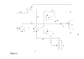
- a first embodiment is shown, where a feed gas stream is led via conduit 1 to a heat exchanger 2 where it is cooled down.
- the resulting cooled feed gas stream is led via conduit 3 to a second heat exchanger 4 where it is further cooled.
- the resulting cooled feed gas stream is led via conduit 5 to expander 6 where it is expanded.
- Part of the expanded feed gas stream is allowed in conduit 7 to liquefy to form a dispersion and this dispersion is led via conduit 7 to a first separator 8, where separation of a aromatic hydrocarbon-enriched liquid phase comprising remaining aliphatic hydrocarbons and an aromatic hydrocarbon-depleted gas phase takes place.
- the aromatic hydrocarbon-enriched liquid phase comprising remaining aliphatic hydrocarbons is led from the bottom of the first separator 8 via conduit 9 to heat exchanger 2, where it is heat exchanged against the incoming feed gas stream.
- the resulting warmer aromatic hydrocarbon-enriched liquid phase comprising remaining aliphatic hydrocarbons is then led via conduit 10 to valve 11, where remaining aliphatic hydrocarbons are flashed off.
- the resulting stream comprising aromatic hydrocarbon-enriched liquid phase and gaseous remaining hydrocarbons is led via conduit 12 to a second separator 13, where separation of remaining aliphatic hydrocarbons takes place. This results in an overhead stream comprising gaseous remaining aliphatic hydrocarbons, which is led via conduit 14 to a compressor 15.
- the resulting compressed remaining aliphatic hydrocarbons stream is led via conduit 16 to the first heat exchanger.
- an aromatic hydrocarbon-depleted hydrocarbon stream is led via conduit 17 to the second heat exchanger 4, where it is heat exchanged against the cooled feed gas stream.
- the resulting heat exchanged aromatic hydrocarbon-depleted stream is led via conduit 18 to a compressor 19, where it is compressed.
- Compressed aromatic hydrocarbon-depleted gas is led from the compressor via conduit 20.
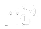
- FIG. 2 a second embodiment is shown, where a feed gas stream is led via conduit 1 to a heat exchanger 2 where it is cooled down.
- the resulting cooled feed gas stream is led via conduit 3 to a second heat exchanger 4 where it is further cooled.
- the resulting cooled feed gas stream is led via conduit 5 to expander 6 where it is expanded.
- Part of the expanded feed gas stream is allowed in conduit 7 to liquefy to form a dispersion and this dispersion is led via conduit 7 to a first separator 8, where separation of a aromatic hydrocarbon-enriched liquid phase comprising remaining aliphatic hydrocarbons and an aromatic hydrocarbon-depleted gas phase takes place.
- the aromatic hydrocarbon-enriched liquid phase comprising remaining aliphatic hydrocarbons is led from the bottom of the first separator 8 via conduit 9 to a booster pump 23, where the pressure is increased.
- the resulting pressurized aromatic hydrocarbon-enriched stream is led via conduit 24 to the first heat exchanger 2, where it is heat exchanged against the incoming feed gas stream.
- the resulting warmer aromatic hydrocarbon-enriched liquid phase comprising remaining aliphatic hydrocarbons is then led via conduit 10 to valve 11, where remaining aliphatic hydrocarbons are flashed off.
- the resulting stream comprising aromatic hydrocarbon-enriched liquid phase and gaseous remaining aliphatic hydrocarbons is led via conduit 12 to a second separator 13, where separation of remaining aliphatic hydrocarbons takes place.
- a feed gas stream is led via conduit 1 to a heat exchanger 2 where it is cooled down.
- the resulting cooled feed gas is led via conduit 3 to a second heat exchanger 4 where it is further cooled.
- the resulting cooled feed gas stream is led via conduit 5 to expander 6 where it is expanded.
- Part of the expanded feed gas stream is allowed in conduit 7 to liquefy to form a dispersion and this dispersion is led via conduit 7 to a first separator 8, where separation of an aromatic hydrocarbon-enriched liquid phase comprising remaining aliphatic hydrocarbons and an aromatic hydrocarbon-depleted gas phase takes place.
- the aromatic hydrocarbon-enriched liquid phase comprising remaining aliphatic hydrocarbons is led from the bottom of the first separator 8 via conduit 9 to a booster pump 23, where the pressure is increased.
- the resulting pressurized aromatic hydrocarbon-enriched stream is led via conduit 24 to the first heat exchanger 2, where it is heat exchanged against the incoming feed gas stream.
- the resulting warmer aromatic hydrocarbon-enriched liquid phase comprising remaining aliphatic hydrocarbons is then led via conduit 10 to valve 11, where remaining aliphatic hydrocarbons are flashed off.
- the resulting stream comprising aromatic hydrocarbon-enriched liquid phase and gaseous remaining aliphatic hydrocarbons is led via conduit 12 to a second separator 13, where separation of remaining aliphatic hydrocarbons takes place.
- an aromatic hydrocarbon-depleted stream is led via conduit 17 to the second heat exchanger 4, where it is heat exchanged against the cooled feed gas stream.
- the resulting heat exchanged aromatic hydrocarbon-depleted stream is led via conduit 18 to a compressor 19, where it is compressed.
- Compressed aromatic hydrocarbon-depleted gas is led from the compressor via conduit 20.
- a feed gas stream is led via conduit 1 to a heat exchanger 2 where it is cooled down.
- the resulting cooled feed gas is led via conduit 3 to a second heat exchanger 4 where it is further cooled.
- the resulting cooled feed gas stream is led via conduit 5 to expander 6 where it is expanded.
- the expanded feed gas stream is allowed to liquefy in conduit 7 to form a dispersion and this dispersion is led via conduit 7 to a first separator 8, where separation of an aromatic hydrocarbon-enriched liquid phase comprising remaining aliphatic hydrocarbons and an aromatic hydrocarbon-depleted gas phase takes place.
- the aromatic hydrocarbon-enriched liquid phase comprising remaining aliphatic hydrocarbons is led from the bottom of the first separator via conduit 9 to a booster pump 23, where the pressure is increased.
- the resulting aromatic hydrocarbon-enriched stream is led via conduit 24 to the first heat exchanger 2, where it is heat exchanged against the incoming feed gas stream.
- the resulting warmer aromatic hydrocarbon-enriched liquid phase comprising remaining aliphatic hydrocarbons is then led via conduit 10 to valve 11, where remaining aliphatic hydrocarbons are flashed off.
- the resulting stream comprising aromatic hydrocarbon-enriched liquid phase and gaseous remaining aliphatic hydrocarbons is led via conduit 12 to a second separator 13, where separation of remaining aliphatic hydrocarbons takes place.
- a feed gas stream is led via conduit 1 to expander 6 where it is expanded.
- Part of the expanded feed gas stream is allowed in conduit 7 to liquefy to form a dispersion and this dispersion is led via conduit 7 to a first separator 8, where separation of an aromatic hydrocarbon-enriched liquid phase comprising remaining aliphatic hydrocarbons and an aromatic hydrocarbon-depleted gas phase takes place.
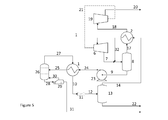
- the aromatic hydrocarbon-enriched liquid phase comprising remaining aliphatic hydrocarbons is led from the bottom of the first separator 8 via conduit 9 to a pump 23, where the pressure is increased.
- the resulting aromatic hydrocarbon-enriched stream is led via conduit 24 to a first heat exchanger 1, where it is heat exchanged against the overhead process stream from the fractionation column 26 described below.
- the resulting heated aromatic hydrocarbon-enriched liquid phase comprising remaining aliphatic hydrocarbons is then led via conduit 25 into a fractionation column 26 with reboiler 29.
- This fractionation column 26 with reboiler 29 produces an overhead stream 27 rich in the light components (such as methane, ethane, CO 2 and H 2 S) and a bottom stream via reboiler 29 rich in the heavier hydrocarbons (such as propane, butanes, pentanes and higher).
- reboiler 29 receives a liquid stream from column 26 which is heated to flash off the lighter fraction in the received stream.
- the flashed off lighter fraction is led back to column 26 through conduit 30.
- the bottom stream is led from the reboiler via conduit 31.
- the light overhead fraction is led through conduit 27 to heat exchanger 1 where it is heat exchanged with the bottom stream from separator 8 and causing the heavier fraction to condense to form a dispersion.
- the dispersion flows through conduit 10 to optional valve 11, where remaining aliphatic hydrocarbons are flashed off.
- the resulting stream comprising aromatic hydrocarbon-enriched liquid phase and gaseous remaining aliphatic hydrocarbons is led via conduit 12 to a second separator 13, where separation of remaining aliphatic hydrocarbons takes place.
- Example 1 (described in reference to Fig. 5)
- This natural gas stream (line 1 in Fig. 5 ), at a pressure of 122 bar and a temperature of 30°C, was used as a feed gas stream and was expanded over a turbo-expander 6 to a pressure of 15 bar. The expansion caused the temperature to drop to -43°C and a fraction of the stream to condense.
- the expanded stream line 7 was combined with a vapour stream 32 (3146 kmoles/hr) from a downstream aliphatic hydrocarbon recovery distillation column 26.
- vapour stream 17 enriched in aliphatic hydrocarbons but depleted in the aromatic hydrocarbons benzene and p-xylene
- liquid stream 9 enriched in benzene and p-xylene and further comprising remaining aliphatic hydrocarbons.
- the vapour stream 17 was heat-exchanged with the above mentioned vapour stream 14 from the downstream aliphatic hydrocarbon distillation column 26 and, subsequently, compressed to a pressure of 34 bar by a compressor 19 that was driven on the shaft of the above mentioned turbo-expander 6, thereby obtaining a product gas stream 20.
- the liquid stream 9 produced in the first separator 8 was pumped to a pressure of 18 bar before heat-exchange with the vapour stream 27 from the downstream aliphatic hydrocarbon distillation column 26, where it was heated up to 2°C. This warm vapour/liquid stream 25 was fed into the distillation column 26.
- the column overhead 27 was heat exchanged with the feed stream 25 to the distillation column 26 to be cooled to - 13°C and was, subsequently, separated in a second separator 13.
- the resulting vapour stream 14 (containing remaining aliphatic hydrocarbons) was heat exchanged with the overhead stream 17 from the first separator 8 as explained above and combined (as stream 32) with the stream 7 and fed into the first phase separator 8.
- the liquid stream 22 (depleted in aliphatic hydrocarbons and containing the benzene and p-xylene) from the second separator 13 was pumped to a pressure of 215 bar and exported as waste, e.g., for re-injection in a subsurface reservoir.
- the liquid bottom stream 28 from the distillation column 26 was a stabilised condensate which contained a large fraction of the benzene and p-xylene present in the feed.
- Table 1 shows the composition, including the amounts of benzene and p-xylene, and certain properties of various streams.
- Table 1 Feed 1 Product gas 20 Liquid stream 22 Liquid stream 31 Properties Flow rate [kmole/hr] 29990 22540 6805 621 Pressure [bar] 122 16.4 215 16.4 Temperature [°C] 30 30 0 30 Amounts [in Mol%, apart from benzene and p-xylene] CO 2 21.0 23.5 14.6 ⁇ 0.01 H 2 S 29.9 15.7 79.8 0.3 N 2 1.7 2.3 ⁇ 0.1 ⁇ 0.01 CH 4 41.6 55.1 0.8 ⁇ 0.01 C 2 -C 7 5.8 3.4 4.8 99.7 Benzene [ppm] 100 ⁇ 1 6 4753 p-xylene [ppm] 100 ⁇ 1 ⁇ 1 4821 Recovery [mol%] Benzene - ⁇ 0.1 1.4 98.4 p-Xylene - ⁇ 0.01 ⁇ 0.1 99.8
Landscapes
- Engineering & Computer Science (AREA)
- Chemical & Material Sciences (AREA)
- Physics & Mathematics (AREA)
- Mechanical Engineering (AREA)
- Thermal Sciences (AREA)
- General Engineering & Computer Science (AREA)
- Oil, Petroleum & Natural Gas (AREA)
- Chemical Kinetics & Catalysis (AREA)
- General Chemical & Material Sciences (AREA)
- Organic Chemistry (AREA)
- Separation By Low-Temperature Treatments (AREA)
Abstract
The invention provides a method of removing aromatic hydrocarbons from a feed gas stream (1) being rich in aliphatic hydrocarbons, the method comprising the steps of:
(a) optionally expanding the feed gas stream (1) in an expander (6) to obtain an expanded feed gas stream (7);
(b) allowing at least part of the aromatic hydrocarbons in the optionally expanded feed gas stream (7) to liquefy to form a dispersion of an aromatic hydrocarbon-enriched liquid phase still comprising a small amount of aliphatic hydrocarbons and a gaseous phase with lowered content of aromatic hydrocarbons;
(c) separating at least part of the aromatic hydrocarbon-enriched liquid phase from the gaseous phase in a first separator (8), thereby obtaining an aromatic hydrocarbon-depleted gas stream (17) and a liquid stream (9) being enriched in aromatic hydrocabons and further comprising remaining aliphatic hydrocarbons;
(d) separating remaining aliphatic hydrocarbons from the liquid stream (9) in a second separator (13), thereby obtaining an overhead stream (14) comprising remaining aliphatic hydrocarbons and a bottom stream (22) depleted in aliphatic hydrocarbons;
(e) leading the overhead stream (14) comprising remaining aliphatic hydrocarbons to a point prior to step (c).
(a) optionally expanding the feed gas stream (1) in an expander (6) to obtain an expanded feed gas stream (7);
(b) allowing at least part of the aromatic hydrocarbons in the optionally expanded feed gas stream (7) to liquefy to form a dispersion of an aromatic hydrocarbon-enriched liquid phase still comprising a small amount of aliphatic hydrocarbons and a gaseous phase with lowered content of aromatic hydrocarbons;
(c) separating at least part of the aromatic hydrocarbon-enriched liquid phase from the gaseous phase in a first separator (8), thereby obtaining an aromatic hydrocarbon-depleted gas stream (17) and a liquid stream (9) being enriched in aromatic hydrocabons and further comprising remaining aliphatic hydrocarbons;
(d) separating remaining aliphatic hydrocarbons from the liquid stream (9) in a second separator (13), thereby obtaining an overhead stream (14) comprising remaining aliphatic hydrocarbons and a bottom stream (22) depleted in aliphatic hydrocarbons;
(e) leading the overhead stream (14) comprising remaining aliphatic hydrocarbons to a point prior to step (c).
Description
- The present invention relates to a method of removing aromatic hydrocarbons from a feed gas stream being rich in aliphatic hydrocarbons, such as natural gas or synthesis gas.
- Natural gas may contain various undesired contaminants, the most prominent ones being hydrogen sulphide (H2S) and carbon dioxide (CO2), other contaminants being for example carbon oxysulphide, mercaptans, alkyl sulphides and aromatic sulphur-containing compounds. These contaminants may add to the costs of the transport and/or treatment. The contaminants may also prove corrosive, hydrogen sulphide is toxic and on combustion produces sulphur dioxide, another pollutant. Moreover, carbon dioxide reduces the heating value of natural gas. It is therefore desirable to remove these contaminants from the natural gas in an early stage. Several methods to remove the above contaminants have been described in the prior art. An example of a method of removing CO2 and H2S has been described in
WO 2010/034627 . - It is an object of the present invention to provide a method of removing aromatic hydrocarbons from a feed gas stream being rich in aliphatic hydrocarbons (such as natural gas). It is a particular object of the present invention to provide a method of removing benzene from a feed gas stream such as natural gas.
- One of the above or other objects can be achieved by the present invention by providing a method of removing aromatic hydrocarbons from a feed gas stream being rich in aliphatic hydrocarbons, the method comprising the steps of:
- (a) optionally expanding the feed gas stream in an expander to obtain an expanded feed gas stream;
- (b) allowing at least part of the aromatic hydrocarbons in the optionally expanded feed gas stream to liquefy to form a dispersion of an aromatic hydrocarbon-enriched liquid phase still comprising a small amount of aliphatic hydrocarbons and a gaseous phase with lowered content of aromatic hydrocarbons;
- (c) separating at least part of the aromatic hydrocarbon-enriched liquid phase from the gaseous phase in a first separator, thereby obtaining an aromatic hydrocarbon-depleted gas stream and a liquid stream being enriched in aromatic hydrocabons and further comprising remaining aliphatic hydrocarbons;
- (d) separating remaining aliphatic hydrocarbons from the liquid stream in a second separator, thereby obtaining an overhead stream comprising remaining aliphatic hydrocarbons and a bottom stream depleted in aliphatic hydrocarbons;
- (e) leading the overhead stream comprising remaining aliphatic hydrocarbons to a point prior to step (c).
- It has now been surprisingly found that using the method according to the present invention, aromatic hydrocarbons can be efficiently removed from a feed gas stream being rich in aliphatic hydrocarbons (such as natural gas).
- In a preferred embodiment of the present invention the aromatic hydrocarbons are homocyclic aromatic hydrocarbons, preferably selected from the group consisting of benzene, toluene, ethylbenzene and xylenes or mixtures thereof. In an especially preferred embodiment, the aromatic hydrocarbons are selected from benzene and xylenes or mixtures thereof.
- Preferably the feed gas stream comprises at least 10 ppmv of the aromatic hydrocarbons, preferably at least 50 ppmv, more preferably at least 100 ppmv. Typically, the feed gas stream comprises at most 10000 ppmv of the aromatic hydrocarbons, preferably below 5000 ppmv.
- The feed gas stream can be any stream being rich in aliphatic hydrocarbons (such as methane, ethane, propane, butane and pentane), but is preferably a methane-rich stream such as natural gas, shale gas, an associated gas stream or a coal bed methane stream. The aliphatic hydrocarbon fraction in such a gas stream is suitably from 10 to 85 mol.% of the gas stream, preferably from 25 to 80 mol.%. According to a preferred embodiment the aliphatic hydrocarbons as present in the feed gas stream comprise at least 40 mol.% of methane, preferably at least 50 mol.%, more preferably at least 70 mol.%. The aliphatic hydrocarbon fraction in the feed gas stream suitably contains from 0.1 to 20 mol.%, suitably from 0.1 to 10 mol.%, of C2-C6 or higher aliphatic hydrocarbon compounds and/or comprises up till 20 mol.%, suitably from 0.1 to 10 mol.% of nitrogen.
- Natural gas streams may become available at a temperature of from -5 to 150°C and a pressure of from 20 to 700 bar.
- In the method of the present invention the feed gas stream may comprise other (non-aliphatic-hydrocarbon) contaminants such as hydrogen sulphide (H2S), carbon dioxide (CO2), carbon oxysulphide, mercaptans, alkyl sulphides and aromatic sulphur-containing compounds (such as thiophenes). The major part of these contaminants may also be removed in the method of the present invention. According to a preferred embodiment of the present invention, the feed stream comprises at least 10 mol.% of a contaminant selected from the group consisting of CO2 and H2S or a mixture thereof. The amount of H2S in the feed gas stream is suitably from 1 ppmv to 80 mol.%, preferably above 5 mol.% more preferably above 10 mol.%, above 20 mol.% or even above 25 mol.% and preferably below 50 mol.%, based on the feed gas stream. The amount of CO2 in the feed gas stream is suitably from 5 to 80 mol.%, preferably above 10 mol.% and below 30 mol.%, based on the feed gas stream. Basis for these amounts is the total volume of aliphatic aromatic hydrocarbons, hydrogen sulphide and/or carbon dioxide and other components that together form the feed gas stream. It is observed that the present method is particularly suitable for feed gas streams comprising large amounts of H2S and/or CO2, e.g. 10 mol.% or more, suitably from 15 to 90 mol.% of the feed gas stream.
- Natural gas streams produced from a subsurface formation typically contain water. In order to prevent the formation of gas hydrates in the present method, at least part of the water is suitably removed. Therefore, the natural gas stream that is used in the present process has preferably been dehydrated. This can be done by conventional processes. A suitable process is the one described in
WO-A 2004/070297 . Other dehydration processes include treatment with molecular sieves or drying processes with glycol. Suitably, water is removed until the amount of water in the natural gas stream comprises at most 50 ppmw, preferably at most 20 ppmw, more preferably at most 1 ppmw of water, based on the total natural gas stream. - Optionally, prior to the optional expanding in step (a) the feed gas stream is cooled in a heat exchanger to obtain a cooled feed gas stream. Suitably, the gas stream is cooled to a temperature in the range of from 0 to 40°C, preferably from 3 to 25°C, depending on the composition of the feed gas stream. The heat exchanger suitably makes use of a heat exchange medium. The heat exchange medium may be any available cold medium.
- In step (a) the optionally cooled feed gas stream is suitably expanded from a pressure ranging from 70 to 200 bar to a pressure ranging from 5 to 30 bar. Such expansion typically will lead to a temperature decrease that is sufficient to start liquefaction of acidic contaminants such as CO2 and H2S. The temperature of the natural gas stream is preferably cooled by expansion from a range of -20 to 50°C to a range from -30 to -80°C.
- The expansion is preferably done in such a way that no solid contaminants are formed. This is suitably achieved by conducting the expansion step in a temperature region at least 3°C, preferably at least 5°C above the temperature at which acidic contaminants begin to solidify. It will be understood that this temperature depends on the type of contaminants and the composition of the mixture and on the pressure. The skilled person will be able to determine the conditions at which the expansion step needs to be conducted.
- The expansion can be achieved by any method known to the skilled person, including methods based on the use of turbo-expanders, so-called Joule-Thomson valves and venturi tubes. It is preferred to at least partly cool the gas stream over a turbo-expander, releasing energy. One advantageous effect of using the turbo-expander is that the almost isentropic expansion in a turbo-expander results in optimal cooling per bar pressure drop and, thus, saves energy for compression of at least part of the aromatic hydrocarbon-depleted gas stream. The person skilled in the art will readily understand that the cooling can be achieved in various ways, including using one or more of ethane, propane, CO2, mixed refrigerants as refrigerants; also, cascade schemes may be used. Since the stream of the aromatic hydrocarbon-depleted gas is smaller than the feed gas stream, the energy is suitably such that the aromatic hydrocarbon-depleted gas may be compressed to an elevated pressure that makes it suitable for transport in a pipeline.
- In step (b), at least part of the aromatic hydrocarbons (possibly together with some other contaminants) in the optionally expanded (and/or possibly cooled) feed gas stream is allowed to liquefy to form a dispersion of an aromatic hydrocarbon-enriched liquid phase still comprising a small amount of aliphatic hydrocarbons and a gaseous phase (which is the main product stream that will typically be liquefied or sent to the customers after optional further processing) with lowered content of aromatic hydrocarbon. This at least partly liquefaction can be achieved in various ways such as cooling by means of an external heat exchanger, expansion, adding of a cold stream, etc. According to the present invention it is particularly preferred that this liquefaction comprises at least expanding, such as indicated in (optional but preferred) step (a).
- A preferred way of achieving this liquefaction (either by expansion or by other means) is to adjust the residence time of the expanded gas stream between step (a) and step (c) such that at least part of the aromatic hydrocarbons will liquefy by a combination of nucleation, growth and coagulation. Thus, a dispersion of an aromatic hydrocarbon-enriched liquid phase in a gaseous phase with lowered content of aromatic hydrocarbons is formed before separation takes place in the first separator in step (c). Preferably, the residence time between the optional expander (and possibly the cooling heat exchanger) and the first separator is in the range of from 0.5 to 5 seconds, in order to allow for sufficient nucleation of the aromatic hydrocarbon-enriched phase followed by sufficient coagulation of droplets to form droplets with a diameter in the micrometer range. The formation of the dispersion suitably takes place in an insulated conduit connecting the expander with the first separator.
- In step (c) at least part of the aromatic hydrocarbon-enriched liquid phase still comprising remaining aliphatic hydrocarbons is separated from the gaseous phase with lowered aromatic hydrocarbon content in a first separator.
- In step (d) remaining aliphatic hydrocarbons are separated from the liquid stream in a second separator, thereby obtaining an overhead stream comprising remaining aliphatic hydrocarbons and a bottom stream depleted in aliphatic hydrocarbons.
- Optionally, step (d) further comprises - prior to separating remaining aliphatic hydrocarbons - one or more of the steps of:
- (d1) increasing the pressure (to typically above 8 bar, preferably above 10 bar and typically below 50 bar, preferably below 20 bar) of the liquid stream being enriched in aromatic hydrocarbons and further comprising remaining aliphatic hydrocarbons to obtain a pressurized liquid stream being enriched in aromatic hydrocarbons and further comprising remaining aliphatic hydrocarbons;
- (d2) heating the (preferably pressurized) liquid stream being enriched in aromatic hydrocarbons and further comprising remaining aliphatic hydrocarbons to obtain a heated liquid stream being enriched in aromatic hydrocarbons and further comprising remaining aliphatic hydrocarbons;
- (d3) fractionation of the (preferably heated and preferably pressurized) liquid stream being enriched in aromatic hydrocarbons and further comprising remaining aliphatic hydrocarbons to obtain a heated liquid stream being enriched in aromatic hydrocarbons and further comprising remaining aliphatic hydrocarbons. Fractionation may be achieved in a trayed or packed column and may comprise a reboiler in the bottom of the column and/or cooler in the top of the column. From the fractionation an overhead stream comprising remaining light aliphatic hydrocarbons and a bottom stream rich in heavier aliphatic hydrocarbons are obtained. The overhead fraction may optionally be cooled and partly condensed to form a dispersion of condensed liquid phase in the gas phase;
- (d4) lowering the pressure of the (preferably heated and preferably pressurized) liquid stream (from the first separator) or optionally overhead cooled dispersed phase from the fractionation column mainly comprising contaminants and further comprising part of remaining aliphatic hydrocarbons, thereby evaporating at least part of the remaining aliphatic hydrocarbons.
- These optional steps result in a better separation of remaining aliphatic hydrocarbons.
- The first and/or the second separator may be any separator suitable for separating the fractions. However, it has been found that two types of separators offer advantages. One preferred type of separator that can used as a first and/or the second separator is a centrifugal separator comprising a bundle of parallel channels that are arranged within a spinning tube parallel to an axis of rotation of the spinning tube. Another preferred type of separator that can be used has been described in
EP-A 48 508 EP-B 195 464 EP-A 48 508 - In a preferred embodiment the separator has been provided with a tangential gas inlet. That has the advantage that the gas is brought into a swirling motion, thereby obtaining a preliminary separation of droplets of liquefied acidic contaminants and gas. In such a situation the separator is preferably provided with an additional liquid outlet upstream of the separating body. It is also possible to provide a central gas inlet with swirl-imparting means. The known separators can be manufactured in a variety of ways. In one specific embodiment of the separator the channels consist of corrugated material wrapped around a shaft or a pipe. The material can consist of paper, cardboard, foil, metal, plastic or ceramic.
- Alternatively, the separator has been composed of a plurality of perforated discs wherein the perforations of the discs form the channels. The channels may be given a varying hydraulic diameter and/or be arranged in a non-parallel way with regard to the central axis of rotation. Although certain embodiments of such separators make it easy to arrange for channels that are non-parallel to the central axis of rotation, it is preferred to have parallel channels. The manufacture of parallel channels is easier and the separation under the process conditions is not substantially affected.
- In a most preferred embodiment, a separator is used comprising:
- 1) a housing comprising a first, second and third separation section for separating liquid from the mixture, wherein the second separation section is arranged below the first separation section and above the third separation section, the respective separation sections are in communication with each other, and the second separation section comprises a rotating coalescer element;
- 2) tangentially arranged inlet means to introduce the mixture into the first separation section;
- 3) means to remove liquid from the first separation section;
- 4) means to remove liquid from the third separation section; and
- 5) means to remove a gaseous stream, lean in liquid, from the third separation section.
- The separator may have a small or large number of channels. The prior art separators have a number of channels suitably ranging from 100 to 1,000,000, preferably from 500 to 500,000. The diameter of the cross-section of the channels can be varied in accordance with the amount of gas and amounts and nature, e.g., droplet size distribution, of contaminants and the desired contaminants removal efficiency. Suitably, the diameter is from 0.05 to 50 mm, preferably from 0.1 to 20 mm, and more preferably from 0.1 to 5 mm. By diameter is understood twice the radius in case of circular cross-sections or the largest diagonal in case of any other shape.
- The size of the separator and in particular of the channels may vary in accordance with the amount of gas to be treated. In
EP-B 286 160 - For the process according to the invention the separator suitably rotates at a velocity of from 100 to 3000 rpm at the temperature and pressure conditions described above.
- In step (e) of the method according to the present invention, the overhead stream comprising remaining aliphatic hydrocarbons is led to a point prior to step c).
- Several ways of executing the invention, and in particular step (e), are possible.
- Without wishing to restrict the invention to specific embodiments, preferred ways of executing the invention, and in particular step (e), will be illustrated using
Figures 1-5 . - For the purpose of this description a single reference number will be assigned to a line as well as a stream carried in that line. Same reference numbers refer to same or similar elements.
- In
Figure 1 a first embodiment is shown, where a feed gas stream is led viaconduit 1 to aheat exchanger 2 where it is cooled down. The resulting cooled feed gas stream is led viaconduit 3 to asecond heat exchanger 4 where it is further cooled. The resulting cooled feed gas stream is led viaconduit 5 toexpander 6 where it is expanded. Part of the expanded feed gas stream is allowed inconduit 7 to liquefy to form a dispersion and this dispersion is led viaconduit 7 to afirst separator 8, where separation of a aromatic hydrocarbon-enriched liquid phase comprising remaining aliphatic hydrocarbons and an aromatic hydrocarbon-depleted gas phase takes place. The aromatic hydrocarbon-enriched liquid phase comprising remaining aliphatic hydrocarbons is led from the bottom of thefirst separator 8 viaconduit 9 toheat exchanger 2, where it is heat exchanged against the incoming feed gas stream. The resulting warmer aromatic hydrocarbon-enriched liquid phase comprising remaining aliphatic hydrocarbons is then led viaconduit 10 tovalve 11, where remaining aliphatic hydrocarbons are flashed off. The resulting stream comprising aromatic hydrocarbon-enriched liquid phase and gaseous remaining hydrocarbons is led viaconduit 12 to asecond separator 13, where separation of remaining aliphatic hydrocarbons takes place. This results in an overhead stream comprising gaseous remaining aliphatic hydrocarbons, which is led viaconduit 14 to acompressor 15. The resulting compressed remaining aliphatic hydrocarbons stream is led viaconduit 16 to the first heat exchanger. From thefirst separator 8, an aromatic hydrocarbon-depleted hydrocarbon stream is led viaconduit 17 to thesecond heat exchanger 4, where it is heat exchanged against the cooled feed gas stream. The resulting heat exchanged aromatic hydrocarbon-depleted stream is led viaconduit 18 to acompressor 19, where it is compressed. Compressed aromatic hydrocarbon-depleted gas is led from the compressor viaconduit 20. - In
Figure 2 a second embodiment is shown, where a feed gas stream is led viaconduit 1 to aheat exchanger 2 where it is cooled down. The resulting cooled feed gas stream is led viaconduit 3 to asecond heat exchanger 4 where it is further cooled. The resulting cooled feed gas stream is led viaconduit 5 toexpander 6 where it is expanded. Part of the expanded feed gas stream is allowed inconduit 7 to liquefy to form a dispersion and this dispersion is led viaconduit 7 to afirst separator 8, where separation of a aromatic hydrocarbon-enriched liquid phase comprising remaining aliphatic hydrocarbons and an aromatic hydrocarbon-depleted gas phase takes place. The aromatic hydrocarbon-enriched liquid phase comprising remaining aliphatic hydrocarbons is led from the bottom of thefirst separator 8 viaconduit 9 to abooster pump 23, where the pressure is increased. The resulting pressurized aromatic hydrocarbon-enriched stream is led viaconduit 24 to thefirst heat exchanger 2, where it is heat exchanged against the incoming feed gas stream. The resulting warmer aromatic hydrocarbon-enriched liquid phase comprising remaining aliphatic hydrocarbons is then led viaconduit 10 tovalve 11, where remaining aliphatic hydrocarbons are flashed off. The resulting stream comprising aromatic hydrocarbon-enriched liquid phase and gaseous remaining aliphatic hydrocarbons is led viaconduit 12 to asecond separator 13, where separation of remaining aliphatic hydrocarbons takes place. This results in an overhead stream comprising gaseous remaining aliphatic hydrocarbons, which is led viaconduits expander 6. From thefirst separator 8, an aromatic hydrocarbon-depleted hydrocarbon stream is led viaconduit 17 to thesecond heat exchanger 4, where it is heat exchanged against the cooled feed gas stream. The resulting heat exchanged aromatic hydrocarbon-depleted hydrocarbon stream is led viaconduit 18 to acompressor 19, where it is compressed. Compressed aromatic hydrocarbon-depleted gas is led from the compressor viaconduit 20. - In
Figure 3 , a third embodiment is shown, where a feed gas stream is led viaconduit 1 to aheat exchanger 2 where it is cooled down. The resulting cooled feed gas is led viaconduit 3 to asecond heat exchanger 4 where it is further cooled. The resulting cooled feed gas stream is led viaconduit 5 toexpander 6 where it is expanded. Part of the expanded feed gas stream is allowed inconduit 7 to liquefy to form a dispersion and this dispersion is led viaconduit 7 to afirst separator 8, where separation of an aromatic hydrocarbon-enriched liquid phase comprising remaining aliphatic hydrocarbons and an aromatic hydrocarbon-depleted gas phase takes place. The aromatic hydrocarbon-enriched liquid phase comprising remaining aliphatic hydrocarbons is led from the bottom of thefirst separator 8 viaconduit 9 to abooster pump 23, where the pressure is increased. The resulting pressurized aromatic hydrocarbon-enriched stream is led viaconduit 24 to thefirst heat exchanger 2, where it is heat exchanged against the incoming feed gas stream. The resulting warmer aromatic hydrocarbon-enriched liquid phase comprising remaining aliphatic hydrocarbons is then led viaconduit 10 tovalve 11, where remaining aliphatic hydrocarbons are flashed off. The resulting stream comprising aromatic hydrocarbon-enriched liquid phase and gaseous remaining aliphatic hydrocarbons is led viaconduit 12 to asecond separator 13, where separation of remaining aliphatic hydrocarbons takes place. This results in an overhead stream comprising gaseous remaining aliphatic hydrocarbons, which is led viaconduits compressor 19, where it is compressed. Typically (not shown inFigure 3 ) part ofstream 14 is sent to a point upstream of thefirst separator 8, similar toFigures 1 and2 . - From the
first separator 8, an aromatic hydrocarbon-depleted stream is led viaconduit 17 to thesecond heat exchanger 4, where it is heat exchanged against the cooled feed gas stream. The resulting heat exchanged aromatic hydrocarbon-depleted stream is led viaconduit 18 to acompressor 19, where it is compressed. Compressed aromatic hydrocarbon-depleted gas is led from the compressor viaconduit 20. - In
Figure 4 , a fourth embodiment is shown, where a feed gas stream is led viaconduit 1 to aheat exchanger 2 where it is cooled down. The resulting cooled feed gas is led viaconduit 3 to asecond heat exchanger 4 where it is further cooled. The resulting cooled feed gas stream is led viaconduit 5 toexpander 6 where it is expanded. The expanded feed gas stream is allowed to liquefy inconduit 7 to form a dispersion and this dispersion is led viaconduit 7 to afirst separator 8, where separation of an aromatic hydrocarbon-enriched liquid phase comprising remaining aliphatic hydrocarbons and an aromatic hydrocarbon-depleted gas phase takes place. The aromatic hydrocarbon-enriched liquid phase comprising remaining aliphatic hydrocarbons is led from the bottom of the first separator viaconduit 9 to abooster pump 23, where the pressure is increased. The resulting aromatic hydrocarbon-enriched stream is led viaconduit 24 to thefirst heat exchanger 2, where it is heat exchanged against the incoming feed gas stream. The resulting warmer aromatic hydrocarbon-enriched liquid phase comprising remaining aliphatic hydrocarbons is then led viaconduit 10 tovalve 11, where remaining aliphatic hydrocarbons are flashed off. The resulting stream comprising aromatic hydrocarbon-enriched liquid phase and gaseous remaining aliphatic hydrocarbons is led viaconduit 12 to asecond separator 13, where separation of remaining aliphatic hydrocarbons takes place. This results in an overhead stream comprising gaseous remaining aliphatic hydrocarbons, which is led viaconduits first separator 8. From thefirst separator 8, an aromatic hydrocarbon-depleted is led viaconduit 17 to thesecond heat exchanger 4, where it is heat exchanged against the cooled feed gas stream. The resulting heat exchanged aromatic hydrocarbon-depleted hydrocarbon stream is led viaconduit 18 to acompressor 19, where it is compressed. Compressed aromatic hydrocarbon-depleted gas is led from the compressor viaconduit 20. - In
Figure 5 , a fifth embodiment is shown, where a feed gas stream is led viaconduit 1 toexpander 6 where it is expanded. Part of the expanded feed gas stream is allowed inconduit 7 to liquefy to form a dispersion and this dispersion is led viaconduit 7 to afirst separator 8, where separation of an aromatic hydrocarbon-enriched liquid phase comprising remaining aliphatic hydrocarbons and an aromatic hydrocarbon-depleted gas phase takes place. The aromatic hydrocarbon-enriched liquid phase comprising remaining aliphatic hydrocarbons is led from the bottom of thefirst separator 8 viaconduit 9 to apump 23, where the pressure is increased. The resulting aromatic hydrocarbon-enriched stream is led viaconduit 24 to afirst heat exchanger 1, where it is heat exchanged against the overhead process stream from thefractionation column 26 described below. The resulting heated aromatic hydrocarbon-enriched liquid phase comprising remaining aliphatic hydrocarbons is then led viaconduit 25 into afractionation column 26 withreboiler 29. Thisfractionation column 26 withreboiler 29 produces anoverhead stream 27 rich in the light components (such as methane, ethane, CO2 and H2S) and a bottom stream viareboiler 29 rich in the heavier hydrocarbons (such as propane, butanes, pentanes and higher). Throughconduit 28reboiler 29 receives a liquid stream fromcolumn 26 which is heated to flash off the lighter fraction in the received stream. The flashed off lighter fraction is led back tocolumn 26 throughconduit 30. The bottom stream is led from the reboiler viaconduit 31. The light overhead fraction is led throughconduit 27 toheat exchanger 1 where it is heat exchanged with the bottom stream fromseparator 8 and causing the heavier fraction to condense to form a dispersion. The dispersion flows throughconduit 10 tooptional valve 11, where remaining aliphatic hydrocarbons are flashed off. The resulting stream comprising aromatic hydrocarbon-enriched liquid phase and gaseous remaining aliphatic hydrocarbons is led viaconduit 12 to asecond separator 13, where separation of remaining aliphatic hydrocarbons takes place. This results in an overhead stream comprising a gaseous fraction, which is led viaconduit 14 to asecond heat exchanger 2 where it is cooled further. Fromheat exchanger 2 it is led viaconduit 32 to thefirst separator 8. A purified aliphatic hydrocarbons stream is led from thesecond separator 13 viaconduit 22. The aromatic hydrocarbon-depleted gas stream from thefirst separator 8 is led viaconduit 17 to heat exchange with the overhead stream from thesecond separator 13. The heated aromatic hydrocarbon-depleted gas stream is then led viaconduit 18 tocompressor 19 where it is compressed. Compressed purified gas is led from the compressor viaconduit 20. - The invention will be illustrated using the following, non-limiting, examples.
- To a dry contaminated natural gas stream of 30000 kmole/hr 100 ppm of benzene and 100 ppm of p-xylene were added thereby obtaining the following approximate composition: 42 mol.% methane, 30 mol.% H2S, 21 mol.% CO2, 6 mol.% C2-C7, 2 mol.% N2, and 100 ppm of both benzene and p-xylene.
- This natural gas stream (
line 1 inFig. 5 ), at a pressure of 122 bar and a temperature of 30°C, was used as a feed gas stream and was expanded over a turbo-expander 6 to a pressure of 15 bar. The expansion caused the temperature to drop to -43°C and a fraction of the stream to condense. The expandedstream line 7 was combined with a vapour stream 32 (3146 kmoles/hr) from a downstream aliphatic hydrocarbonrecovery distillation column 26. Subsequently, the combined stream was phase separated in afirst separator 8 to produce a vapour stream 17 (enriched in aliphatic hydrocarbons but depleted in the aromatic hydrocarbons benzene and p-xylene) and a liquid stream 9 (enriched in benzene and p-xylene and further comprising remaining aliphatic hydrocarbons). Thevapour stream 17 was heat-exchanged with the above mentionedvapour stream 14 from the downstream aliphatichydrocarbon distillation column 26 and, subsequently, compressed to a pressure of 34 bar by acompressor 19 that was driven on the shaft of the above mentioned turbo-expander 6, thereby obtaining aproduct gas stream 20. Theliquid stream 9 produced in thefirst separator 8 was pumped to a pressure of 18 bar before heat-exchange with thevapour stream 27 from the downstream aliphatichydrocarbon distillation column 26, where it was heated up to 2°C. This warm vapour/liquid stream 25 was fed into thedistillation column 26. The column overhead 27 was heat exchanged with thefeed stream 25 to thedistillation column 26 to be cooled to - 13°C and was, subsequently, separated in asecond separator 13. The resulting vapour stream 14 (containing remaining aliphatic hydrocarbons) was heat exchanged with theoverhead stream 17 from thefirst separator 8 as explained above and combined (as stream 32) with thestream 7 and fed into thefirst phase separator 8. The liquid stream 22 (depleted in aliphatic hydrocarbons and containing the benzene and p-xylene) from thesecond separator 13 was pumped to a pressure of 215 bar and exported as waste, e.g., for re-injection in a subsurface reservoir. - The
liquid bottom stream 28 from thedistillation column 26 was a stabilised condensate which contained a large fraction of the benzene and p-xylene present in the feed. - Table 1 below shows the composition, including the amounts of benzene and p-xylene, and certain properties of various streams.
Table 1 Feed 1Product gas 20Liquid stream 22Liquid stream 31Properties Flow rate [kmole/hr] 29990 22540 6805 621 Pressure [bar] 122 16.4 215 16.4 Temperature [°C] 30 30 0 30 Amounts [in Mol%, apart from benzene and p-xylene] CO2 21.0 23.5 14.6 <0.01 H2S 29.9 15.7 79.8 0.3 N2 1.7 2.3 <0.1 <0.01 CH4 41.6 55.1 0.8 <0.01 C2-C7 5.8 3.4 4.8 99.7 Benzene [ppm] 100 <1 6 4753 p-xylene [ppm] 100 <1 <1 4821 Recovery [mol%] Benzene - <0.1 1.4 98.4 p-Xylene - <0.01 <0.1 99.8 - As can be seen from Table 1, the aromatic hydrocarbons p-xylene and benzene were effectively removed from the feed gas stream thereby obtaining a
product stream 20 being rich in methane and containing significantly reduced amounts of p-xylene and benzene. - Also it was found that, when repeating Example 1 whilst adding 100 ppm of methyl mercaptan, carbon oxysulphide, CS2 and/or thiophene, these components were effectively removed as well thereby obtaining a product stream containing significantly reduced amounts of these components.
Claims (5)
- A method of removing aromatic hydrocarbons from a feed gas stream (1) being rich in aliphatic hydrocarbons, the method comprising the steps of:(a) optionally expanding the feed gas stream (1) in an expander (6) to obtain an expanded feed gas stream (7);(b) allowing at least part of the aromatic hydrocarbons in the optionally expanded feed gas stream (7) to liquefy to form a dispersion of an aromatic hydrocarbon-enriched liquid phase still comprising a small amount of aliphatic hydrocarbons and a gaseous phase with lowered content of aromatic hydrocarbons;(c) separating at least part of the aromatic hydrocarbon-enriched liquid phase from the gaseous phase in a first separator (8), thereby obtaining an aromatic hydrocarbon-depleted gas stream (17) and a liquid stream (9) being enriched in aromatic hydrocabons and further comprising remaining aliphatic hydrocarbons;(d) separating remaining aliphatic hydrocarbons from the liquid stream (9) in a second separator (13), thereby obtaining an overhead stream (14) comprising remaining aliphatic hydrocarbons and a bottom stream (22) depleted in aliphatic hydrocarbons;(e) leading the overhead stream (14) comprising remaining aliphatic hydrocarbons to a point prior to step (c).
- The method according to claim 1, wherein the aromatic hydrocarbons are homocyclic aromatic hydrocarbons, preferably selected from the group consisting of benzene, toluene, ethylbenzene and xylenes or mixtures thereof.
- The method according to claim 1 or 2, wherein the feed gas stream (1) comprises at least 10 ppmv of the aromatic hydrocarbons, preferably from 50 to 5000 ppmv.
- The method according to any one of the preceding claims, wherein the aliphatic hydrocarbons as present in the feed gas stream (1) comprise at least 40 mol.% of methane, preferably at least 75 mol.%.
- The method according to any one of the preceding claims, wherein the feed gas stream (1) comprises at least 10 mol.% of a contaminant selected from the group consisting of CO2 and H2S or a mixture thereof.
Priority Applications (1)
| Application Number | Priority Date | Filing Date | Title |
|---|---|---|---|
| EP11171885A EP2540371A1 (en) | 2011-06-29 | 2011-06-29 | Method of removing aromatic hydrocarbons from a feed gas stream being rich in aliphatic hydrocarbons |
Applications Claiming Priority (1)
| Application Number | Priority Date | Filing Date | Title |
|---|---|---|---|
| EP11171885A EP2540371A1 (en) | 2011-06-29 | 2011-06-29 | Method of removing aromatic hydrocarbons from a feed gas stream being rich in aliphatic hydrocarbons |
Publications (1)
| Publication Number | Publication Date |
|---|---|
| EP2540371A1 true EP2540371A1 (en) | 2013-01-02 |
Family
ID=44650982
Family Applications (1)
| Application Number | Title | Priority Date | Filing Date |
|---|---|---|---|
| EP11171885A Withdrawn EP2540371A1 (en) | 2011-06-29 | 2011-06-29 | Method of removing aromatic hydrocarbons from a feed gas stream being rich in aliphatic hydrocarbons |
Country Status (1)
| Country | Link |
|---|---|
| EP (1) | EP2540371A1 (en) |
Cited By (1)
| Publication number | Priority date | Publication date | Assignee | Title |
|---|---|---|---|---|
| CN106595223A (en) * | 2016-11-22 | 2017-04-26 | 西安长庆科技工程有限责任公司 | System and method for recycling propane and C3<+> hybrid hydrocarbon in natural gas |
Citations (9)
| Publication number | Priority date | Publication date | Assignee | Title |
|---|---|---|---|---|
| EP0048508A2 (en) | 1980-09-18 | 1982-03-31 | Shell Internationale Researchmaatschappij B.V. | Apparatus for treating mixtures of liquid and gas |
| EP0195464B1 (en) | 1985-03-05 | 1989-04-19 | Shell Internationale Researchmaatschappij B.V. | Column for removing liquid from a gas |
| EP0286160B1 (en) | 1987-03-25 | 1990-05-23 | B B Romico Beheer B.V. | Rotational particle separator |
| US5502266A (en) * | 1992-10-19 | 1996-03-26 | Chevron Research And Technology Company, A Division Of Chevron U.S.A. Inc. | Method of separating well fluids produced from a gas condensate reservoir |
| DE19622692C1 (en) * | 1996-06-05 | 1998-01-15 | Linde Ag | Liquefaction of hydrocarbon-rich gas stream containing aromatic and heavy hydrocarbon(s) |
| WO2001069149A1 (en) * | 2000-03-15 | 2001-09-20 | Den Norske Stats Oljeselskap A.S. | Natural gas liquefaction process |
| DE102004046342A1 (en) * | 2004-09-24 | 2006-03-30 | Linde Ag | Removal of unwanted components (e.g. heavy hydrocarbon) from hydrocarbon-rich gas stream comprises adding heavy hydrocarbon-containing fraction to the gas stream; separating mixed fraction; and liquefying gas fraction |
| WO2010034627A1 (en) | 2008-09-23 | 2010-04-01 | Shell Internationale Research Maatschappij B.V. | Process for removing gaseous contaminants from a feed gas stream comprising methane and gaseous contaminants |
| WO2011026170A1 (en) * | 2009-09-01 | 2011-03-10 | Cool Energy Limited | Process and apparatus for reducing the concentration of a sour species in a sour gas |
-
2011
- 2011-06-29 EP EP11171885A patent/EP2540371A1/en not_active Withdrawn
Patent Citations (9)
| Publication number | Priority date | Publication date | Assignee | Title |
|---|---|---|---|---|
| EP0048508A2 (en) | 1980-09-18 | 1982-03-31 | Shell Internationale Researchmaatschappij B.V. | Apparatus for treating mixtures of liquid and gas |
| EP0195464B1 (en) | 1985-03-05 | 1989-04-19 | Shell Internationale Researchmaatschappij B.V. | Column for removing liquid from a gas |
| EP0286160B1 (en) | 1987-03-25 | 1990-05-23 | B B Romico Beheer B.V. | Rotational particle separator |
| US5502266A (en) * | 1992-10-19 | 1996-03-26 | Chevron Research And Technology Company, A Division Of Chevron U.S.A. Inc. | Method of separating well fluids produced from a gas condensate reservoir |
| DE19622692C1 (en) * | 1996-06-05 | 1998-01-15 | Linde Ag | Liquefaction of hydrocarbon-rich gas stream containing aromatic and heavy hydrocarbon(s) |
| WO2001069149A1 (en) * | 2000-03-15 | 2001-09-20 | Den Norske Stats Oljeselskap A.S. | Natural gas liquefaction process |
| DE102004046342A1 (en) * | 2004-09-24 | 2006-03-30 | Linde Ag | Removal of unwanted components (e.g. heavy hydrocarbon) from hydrocarbon-rich gas stream comprises adding heavy hydrocarbon-containing fraction to the gas stream; separating mixed fraction; and liquefying gas fraction |
| WO2010034627A1 (en) | 2008-09-23 | 2010-04-01 | Shell Internationale Research Maatschappij B.V. | Process for removing gaseous contaminants from a feed gas stream comprising methane and gaseous contaminants |
| WO2011026170A1 (en) * | 2009-09-01 | 2011-03-10 | Cool Energy Limited | Process and apparatus for reducing the concentration of a sour species in a sour gas |
Non-Patent Citations (1)
| Title |
|---|
| DE HEMPTINNE J-C: "Benzene crystallisation risks in LNG processes", AICHE SPRING MEETING. NATURAL GAS UTILIZATION CONFERENCE, X, US, no. 5, 1 January 2005 (2005-01-01), pages 160 - 174, XP009097537 * |
Cited By (1)
| Publication number | Priority date | Publication date | Assignee | Title |
|---|---|---|---|---|
| CN106595223A (en) * | 2016-11-22 | 2017-04-26 | 西安长庆科技工程有限责任公司 | System and method for recycling propane and C3<+> hybrid hydrocarbon in natural gas |
Similar Documents
| Publication | Publication Date | Title |
|---|---|---|
| JP5997798B2 (en) | Nitrogen removal by isobaric open frozen natural gas liquid recovery | |
| US6128919A (en) | Process for separating natural gas and carbon dioxide | |
| AU2007319977B2 (en) | Configurations and methods for gas condensate separation from high-pressure hydrocarbon mixtures | |
| CA2583120C (en) | Integrated acid gas and sour gas reinjection process | |
| US12215922B2 (en) | Integrated heavy hydrocarbon and BTEX removal in LNG liquefaction for lean gases | |
| JP4571934B2 (en) | Hydrocarbon gas treatment | |
| US12098882B2 (en) | Heavy hydrocarbon and BTEX removal from pipeline gas to LNG liquefaction | |
| US20030029190A1 (en) | Hydrocarbon gas processing | |
| WO2008086265A1 (en) | Carbon dioxide fractionalization process | |
| WO2013095828A1 (en) | Method of separating carbon dioxide from liquid acid gas streams | |
| CA2691743A1 (en) | Method and system for removing hydrogen sulphide (h2s) from a natural gas stream | |
| AU2009272889A1 (en) | Two stage process for producing purified gas | |
| AU2002363532A1 (en) | Configurations and methods for improved NGL recovery | |
| WO2018048478A1 (en) | Pretreatment of natural gas prior to liquefaction | |
| CN1612998A (en) | Device and method for improving NGL recovery rate | |
| CN102159298A (en) | Process for removing gaseous contaminants from a feed gas stream comprising methane and gaseous contaminants | |
| AU2009253116B2 (en) | Producing purified hydrocarbon gas from a gas stream comprising hydrocarbons and acidic contaminants | |
| WO2014036322A1 (en) | Configurations and methods for offshore ngl recovery | |
| US11447710B2 (en) | Separation of sulfurous materials | |
| WO2020123814A1 (en) | Integrated heavy hydrocarbon and btex removal in lng liquefaction for lean gases | |
| AU2013330240B2 (en) | Separating carbon dioxide from natural gas liquids | |
| US20100005721A1 (en) | Process for the removal of acidic contaminants from a natural gas stream | |
| US20120324941A1 (en) | Process for producing a contaminant-depleted hydrocarbon gas stream with improved hydrocarbon recovery | |
| CA2949014C (en) | Method of separating a natural gas liquid feed stream |
Legal Events
| Date | Code | Title | Description |
|---|---|---|---|
| PUAI | Public reference made under article 153(3) epc to a published international application that has entered the european phase |
Free format text: ORIGINAL CODE: 0009012 |
|
| AK | Designated contracting states |
Kind code of ref document: A1 Designated state(s): AL AT BE BG CH CY CZ DE DK EE ES FI FR GB GR HR HU IE IS IT LI LT LU LV MC MK MT NL NO PL PT RO RS SE SI SK SM TR |
|
| AX | Request for extension of the european patent |
Extension state: BA ME |
|
| STAA | Information on the status of an ep patent application or granted ep patent |
Free format text: STATUS: THE APPLICATION IS DEEMED TO BE WITHDRAWN |
|
| 18D | Application deemed to be withdrawn |
Effective date: 20130703 |