EP2540210A1 - Medical instrument holding device - Google Patents
Medical instrument holding device Download PDFInfo
- Publication number
- EP2540210A1 EP2540210A1 EP11812533A EP11812533A EP2540210A1 EP 2540210 A1 EP2540210 A1 EP 2540210A1 EP 11812533 A EP11812533 A EP 11812533A EP 11812533 A EP11812533 A EP 11812533A EP 2540210 A1 EP2540210 A1 EP 2540210A1
- Authority
- EP
- European Patent Office
- Prior art keywords
- medical device
- section
- fixing
- supporting apparatus
- supporting
- Prior art date
- Legal status (The legal status is an assumption and is not a legal conclusion. Google has not performed a legal analysis and makes no representation as to the accuracy of the status listed.)
- Granted
Links
Images




Classifications
-
- A—HUMAN NECESSITIES
- A61—MEDICAL OR VETERINARY SCIENCE; HYGIENE
- A61B—DIAGNOSIS; SURGERY; IDENTIFICATION
- A61B1/00—Instruments for performing medical examinations of the interior of cavities or tubes of the body by visual or photographical inspection, e.g. endoscopes; Illuminating arrangements therefor
- A61B1/00131—Accessories for endoscopes
- A61B1/0014—Fastening element for attaching accessories to the outside of an endoscope, e.g. clips, clamps or bands
-
- A—HUMAN NECESSITIES
- A61—MEDICAL OR VETERINARY SCIENCE; HYGIENE
- A61B—DIAGNOSIS; SURGERY; IDENTIFICATION
- A61B1/00—Instruments for performing medical examinations of the interior of cavities or tubes of the body by visual or photographical inspection, e.g. endoscopes; Illuminating arrangements therefor
- A61B1/00112—Connection or coupling means
- A61B1/00121—Connectors, fasteners and adapters, e.g. on the endoscope handle
- A61B1/00128—Connectors, fasteners and adapters, e.g. on the endoscope handle mechanical, e.g. for tubes or pipes
-
- A—HUMAN NECESSITIES
- A61—MEDICAL OR VETERINARY SCIENCE; HYGIENE
- A61B—DIAGNOSIS; SURGERY; IDENTIFICATION
- A61B1/00—Instruments for performing medical examinations of the interior of cavities or tubes of the body by visual or photographical inspection, e.g. endoscopes; Illuminating arrangements therefor
- A61B1/00147—Holding or positioning arrangements
- A61B1/00149—Holding or positioning arrangements using articulated arms
-
- A—HUMAN NECESSITIES
- A61—MEDICAL OR VETERINARY SCIENCE; HYGIENE
- A61B—DIAGNOSIS; SURGERY; IDENTIFICATION
- A61B90/00—Instruments, implements or accessories specially adapted for surgery or diagnosis and not covered by any of the groups A61B1/00 - A61B50/00, e.g. for luxation treatment or for protecting wound edges
- A61B90/50—Supports for surgical instruments, e.g. articulated arms
- A61B2090/5025—Supports for surgical instruments, e.g. articulated arms with a counter-balancing mechanism
-
- A—HUMAN NECESSITIES
- A61—MEDICAL OR VETERINARY SCIENCE; HYGIENE
- A61B—DIAGNOSIS; SURGERY; IDENTIFICATION
- A61B90/00—Instruments, implements or accessories specially adapted for surgery or diagnosis and not covered by any of the groups A61B1/00 - A61B50/00, e.g. for luxation treatment or for protecting wound edges
- A61B90/50—Supports for surgical instruments, e.g. articulated arms
- A61B2090/508—Supports for surgical instruments, e.g. articulated arms with releasable brake mechanisms
Definitions
- the present invention relates to a supporting apparatus for medical device, which supports an endoscope for observing inside of a body cavity of a subject to inspect, an operation microscope for observing inside of a trepanned head, or a treatment instrument for curative treatment on an affected part.
- a supporting apparatus for medical device which comprises a balance mechanism to maintain a three-dimensional balance owing to the principle of balance
- a supporting apparatus for medical device which comprises a balance mechanism to maintain a balance in up and down directions owing to reaction force of a spring.
- a supporting apparatus for medical device which comprises a balance mechanism to support a hard mirror in a state of balancing a medical microscope.
- Jpn. Pat. Appln. KOKAI Publication No. 57-860806 discloses a balance mechanism which maintains a balance in up and down directions owing to reaction force of a spring.
- Jpn. Pat. Appln. KOKAI Publications No. 63-36481 and 7-227398 disclose balance mechanisms which maintain a three-dimensional balance owing to the principle of balance.
- Jpn. Pat. Appln. KOKAI Publication No. 57-860806 discloses a supporting apparatus for medical device, which comprises a parallelogram link mechanism. A balance in up and down directions of an observation apparatus is maintained by providing an adjustable spring within this parallelogram link mechanism.
- the supporting apparatus for medical device disclosed in Jpn. Pat. Appln. KOKAI Publication No. 63-36481 is configured to maintain a three-dimensional balance of an optical observation apparatus by providing a pivot fulcrum on a line connecting centroids of the optical observation apparatus and a counter weight.
- a supporting apparatus for surgical instrument disclosed in Jpn. Pat. Appln. KOKAI Publication No. 7-227398 is configured to fix/release a joint part by an electromagnetic brake built in the joint part, in addition to the configuration of maintaining a three-dimensional balance of an optical observation apparatus by providing a pivot fulcrum on a line connecting centroids of the optical observation apparatus and a counter weight.
- the invention has an object of providing a supporting apparatus for medical device, which can maintain a balance of a medical device at an arbitrary position and can prevent a tip end of an arm mechanism from jumping up even after detaching the medical device.
- a supporting apparatus for a medical device comprising: a supporting section comprising (i) a pedestal configured to be set on a setting section of a floor, a ceiling or a trolley, and (ii) a balance mechanism connected to the pedestal, comprising an arm mechanism comprising a plurality of joint parts, and configured to move or tilt a medical device held by the arm mechanism and to balance a weight of the medical device and the arm mechanism; a brake section configured to switch between a fixed state where at least one of the joint parts of the holding section is fixed and a fixing release state where the joint parts are not fixed; and an input section which gives an instruction on switching between the fixed state and the fixing release state of the brake section.
- FIGS. 1 to 8 show the first embodiment of the invention.
- FIG. 1 shows a schematic configuration of an entire supporting apparatus 2 for medical device, according to the present embodiment, which supports a flexible endoscope 11 as a medical device to be movable and tiltable.
- FIG. 1 shows a stand unit 2 in the supporting apparatus 2 for medical device.
- a plurality of casters 22 for movement are attached below a base plate 1a as a base.
- a post 3 is provided to stand in a perpendicular direction.
- a horizontal arm part 3a which is bent in a horizontal direction.
- the supporting part 2A comprises a link mechanism part (arm mechanism) 4 made of a parallelogram link which supports the flexible endoscope 11 to be movable and tiltable.
- the link mechanism part 4 comprises an upper plate 15, a lower plate 16, a rear-link end part 17, and a tip-link end part 18.
- the upper plate 15 is a plate-type member having a substantially U-shaped cross-section.
- a shaft 38 extending in the horizontal directions is inserted in and between two end plates 15a and 15b of the upper plate 15.
- Two flange parts 38a in contact with the two end plates 15a of the upper end plate 15 are formed on the shaft 38.
- One of the flange parts 38a is fixed by a bolt to one end plate 15a of the upper plate 15.
- the other one of the flange parts 38a not shown in the figure is also fixed by a bolt to the other one end plate 15a of the upper plate 15.
- the lower plate 16 is a plate-type member having a substantially U-shaped cross-section.
- a shaft 34 extended in a horizontal direction is inserted in and between two end plates 15a and 15b of the lower plate 16.
- An insertion hole 17a in which the shaft 38 of the upper plate 15 is inserted and an insertion hole 17b in which the shaft 34 of the lower plate 16 is inserted are formed in the rear link end part 17. Further, a base end part of the upper plate 15 (a connection part to the rear link end part 17) is supported to be pivotal about a rotation shaft 04 by the shaft 38 inserted in the insertion hole 17a of the rear link end part 17. Between the upper plate 15 and the rear link end part 17, a first joint 4k1 is formed. Similarly, a base end of the lower plate 16 (connection part to the rear link end 17) is supported to be pivotal about a rotation shaft 05 inserted in the insertion hole 17b of the rear link end part 17 by the shaft 34. Between the lower plate 16 and the rear link end part 17, a second joint 4k2 is formed.
- a tip end part of the upper plate 15 (connection part to the rear link end part 18) is supported at the tip-link end part 18, to be pivotal about a rotation axis 07 by a shaft 202.
- a third joint 4k3 is formed between the upper plate 15 and the tip-link end part 18.
- a tip end part of the lower plate 16 (connection part to the tip-link end part 18) is supported at the tip-link end part 18, to be pivotal about a rotation axis 08 by a shaft 203.
- a fourth joint 4k4 is formed between the lower plate 16 and the tip-link end part 18.
- the link mechanism part 4 is supported to be movable to arbitrary upper and lower positions, in a manner that the parallelogram link deforms to a horizontal position denoted by a continuous line in FIG. 1 , an upwardly pivoted position denoted by a virtual line in FIG. 1 , and a downwardly pivoted position not shown.
- a first joint rotation part 20k and a first lock part 20 At the tip end part of the horizontal arm part 3a, there are provided a first joint rotation part 20k and a first lock part 20.
- the first joint rotation part 20k is supported to be pivotal about a rotation axis O1 in a perpendicular direction.
- the first lock part 20 switches to either a fixed state of fixing movement of the first joint rotation part 20k or a fixing release state of releasing fixing of the first joint rotation part 20k.
- a support member 5 of the link mechanism part 4 is connected to the first lock part 20.
- the support member 5 is supported to be pivotal about the rotation axis O1 in the direction perpendicular to the first lock part 20.
- a second joint rotation part 21k Above the tip end of the tip-link end part 18 of the link mechanism part 4, there are provided a second joint rotation part 21k and a second lock part 21.
- the second joint rotation part 21k is supported to be pivotal about a rotation axis 02 in the perpendicular direction.
- the second lock part 21 switches to either a fixed state of fixing movement of the second joint rotation part 21k or a release state of releasing fixing of the second joint rotation part 21k.
- the support member 7 of the supporting part 6 of the flexible endoscope 11 as a medical device is connected to the second lock part 21.
- the support member 7 is supported to be pivotal about the rotation axis 02 in the direction perpendicular to the second lock part 21.
- the supporting part 6 fixes the flexible endoscope 11 as a medical device by a manual brake 25, to be tiltable about the center line of the manual brake 25 as a center.
- the flexible endoscope 11 is configured by, for example, an electric bendable endoscope.
- the electric bendable endoscope comprises an elongate insertion part 8 to be inserted into a body cavity, and a drive part 9 connected to a base end part of the insertion part 8.
- the drive part 9 is attached or namely fixed to the supporting part 6 of the flexible endoscope 11.
- the base end part of the insertion part 8 is detachably connected to the drive part 9.
- the drive part 9 of the flexible endoscope 11 is connected to a tip end of the supporting part 6, to be pivotal about a rotation axis 03.
- a bending part 8a which can be operated, for example, to bend in four directions of up, down, left, and right directions. Further, inside the insertion part 8, there are provided a plurality of bending operation wires (UD wire 8w1 for up and down directions, and RL wire 8w2 in left and right directions).
- the drive part 9 is also provided with, for example, two drive motors 9m1 and 9m2, and two drive force transmission mechanisms 9d1 and 9d2. These drive motors 9m1 and 9m2 generate drive forces to draw and drive the bending operation wires 8w1 and 8w2.
- the drive force transmission mechanisms 9d1 and 9d2 respectively convert drive forces of the drive motors 9m1 and 9m2 into traction forces for the bending operation wires 8w1 and 8w2.
- one drive motor 9m1 is a UD motor for driving the bending part 8a to bend in the up and down directions (up (U) direction and down (D) direction), and the other drive motor 9m2 is a RL motor for driving the bending part 8a to bend in the left and right directions (right (R) and left (L) directions).
- connection part 8b which is detachably connected to the drive part 9 is provided at a base end part of the insertion part 8.
- Clutch parts 8c1, 8c2, 9c1, and 9c2 are provided at a connection part between the connection part 8b of the insertion part 8 and the drive part 9.
- the clutch parts 8c1, 8c2, 9c1, and 9c2 shut off or connect drive forces which are transmitted between the bending operation wires 8w1 and 8w2 and the drive force transmission mechanisms 9d1 and 9d2.
- the clutch parts 9c1 and 9c2 of the drive force transmission mechanisms 9d1 and 9d2 and the clutch parts 8c1 and 8c2 of the connection part 8b of the insertion part 8 are separably engaged to connect.
- the drive force from one drive motor 9m1 of the drive part 9 is transmitted from the drive force transmission mechanism 9d1 on a side of the drive part 9 through engaged parts between the clutch parts 9c1 and 8c1.
- the bending operation wire 8w1 is drawn to operate the bending part 8a to bend in an operating direction of the bending operation wire 8w1.
- the drive force from the other one drive motor 9m2 of the drive part 9 is transmitted from the drive force transmission mechanism 9d2 on the side of the drive part 9 through engaged parts between the clutch parts 9c2 and 8c2.
- the bending operation wire 8w1 is drawn to operate the bending part 8a to bend in an operating direction of the bending operation wire 8w2.
- the supporting apparatus 2 for medical device comprises a balance mechanism 201 which maintains a balance of the flexible endoscope 11 attached to the tip end side of the link mechanism part 4, at an arbitrary upper or lower position, owing to reaction force of the compression spring 12.
- an end of the compression spring 12 is fixed to an upper end part of the tip-link end part 18.
- the other end of the compression spring 12 is fixed to a lower end part of the rear link end part 17. Owing to the reaction force of the compression spring 12, the weight of the flexible endoscope 11 and the link mechanism part 4 are balanced by the reaction force of the compression spring 12, owing to reaction force of the compression spring 12.
- the supporting apparatus 2 for medical device is provided with a lock part (brake part) 13 which can switch at least one joint part of the link mechanism part 4 at the supporting part 2A of the flexible endoscope 11, i.e., a first joint 4k1 in the present embodiment between a fixed state of fixing the first joint 4k1 and a fixing release state of releasing the fixed first joint 4k1.
- a lock part brake part 13 which can switch at least one joint part of the link mechanism part 4 at the supporting part 2A of the flexible endoscope 11, i.e., a first joint 4k1 in the present embodiment between a fixed state of fixing the first joint 4k1 and a fixing release state of releasing the fixed first joint 4k1.
- the lock part 13 is provided with a non-excitation-operation-type electromagnetic brake 31.
- This non-excitation-operation-type electromagnetic brake 31 comprises an armature 32 as a movable part and a stator 37 as a stationary part.
- the stator 37 is fixed to the rear link end part 17 to be coaxial with a rotation axis 04.
- the stator 37 of the non-excitation-operation-type electromagnetic brake 31 internally comprises a permanent magnet 35 and a coil 36.
- the shaft 38 is rotatably supported by a bearing.
- a disc-type plate 33 is fixed to one end surface of the shaft 38.
- the armature 32 is opposed to the plate 33 over a plate spring 39.
- An end part of the plate spring 39 is fixed to the plate 33, and the other end part thereof is fixed to the armature 32.
- the armature 32 is fixed to the plate 33 over the plate spring 39.
- a suctioned state of the armature 32 due to the permanent magnet 35 is controlled by switching conduction of the stator 37 to the coil 36.
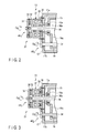
- the armature 32 is maintained in a fixed state in which the armature 32 is suctioned to the stator 37, due to the magnetic force of the permanent magnet 35, as shown in FIG. 3 .
- the shaft 38 is maintained fixed to the rear link end part 17. Therefore, the shaft 38 in the upper plate 15 is maintained not rotatable, and is thereby maintained in a fixed state of fixing movement of the link mechanism part 4.
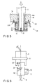
- FIG. 5 shows a schematic configuration of the first joint rotation part 20k and the first lock part 20.
- An insertion hole 45a in which a shaft 5s at a lower end part of a support member 5 is inserted to be coaxial with the rotation axis O1, is formed in the tip end part 45 of the horizontal arm part 3a of the post 3.
- the shaft 5s is supported to be rotatable in the insertion hole 45a at the tip end part 45 of the horizontal arm part 3a through a bearing.
- the first joint rotation part 20k which supports the link mechanism part 4 to be pivotal about the rotation axis O1 by the supporting member 5.
- the first lock part 20 is provided with a non-excitation-operation-type electromagnetic brake 48 which has the same configuration as the lock part 13 of the first joint 4k1.
- This non-excitation-operation-type electromagnetic brake 48 comprises a stator 49 as a stationary part and an armature 51 as a movable part.
- the stator 49 is fixed to the tip end part 45 to be coaxial with the rotation axis 04.
- the stator 49 of the non-excitation-operation-type electromagnetic brake 48 internally comprises a permanent magnet 47 and a coil 46. Inside the stator 49, a shaft 5s is rotatably inserted.
- the disc-type plate 50 is fixed to a lower end part of the supporting member 5. Between the plate 50 and the armature 51, the plate spring 52 is inserted. An end part of the plate spring 52 is fixed to the plate 50, and the other end part thereof is fixed to the armature 51.
- the suctioned state of the armature 51 due to the permanent magnet 47 is controlled by switching conduction to the coil 46 of the stator 49.
- the armature 51 is maintained in a fixed state in which the armature 51 is suctioned to the stator 49 due to magnetic force of the permanent magnet 47.
- the shaft 5 is maintained fixed to the tip end part 45 of the horizontal arm part 3a. Therefore, the shaft 5s of at the lower end part of the supporting member 5 is maintained to be not rotatable.
- a second joint rotation part 21k and a second lock part 21 have the same structures as the first joint rotation part 20k and the first lock part 20, and will be therefore omitted from descriptions.
- the supporting apparatus 2 for medical device is provided with a brake switch 19 equivalent to an input part which instructs switching between a fixed state and a fixing release state for the lock part 13, first lock part 20, and second lock part 21.
- the brake switch 19 is provided on an operation part 10 of the flexible endoscope 11.
- the brake system of the brake switch 19 exemplifies an alternate method.
- FIG. 6 shows a separate state of the drive part 9 of the flexible endoscope 11 and the connection part of the insertion part 8.
- a transparent photo interrupter 23 as a detector which detects attachment/detachment of the flexible endoscope 11 is attached to the connection part of the drive part 9 to the insertion part 8.
- a detection target 2 for the photo interrupter 23 is attached to the insertion part 8.
- a controller (control unit) 14 is provided on the base plate 1a of the stand unit 1. As shown in FIG. 7 , the controller 14 is connected to the brake switch 19, photo interrupter 23, lock part 13, first lock part 20, and each of the electromagnetic brakes 31 and 48 of the second lock part 21. Further, when the photo interrupter 23 detects a state of the insertion part 8 detached from the drive part 9 of the flexible endoscope 11, a control signal to switch the lock part 13, first lock part 20, and each of the electromagnetic brakes 31 and 48 of the second lock part 21 is output, based on a detection signal from the photo interrupter 23.
- the first joint 4k1 of the link mechanism part 4, first joint rotation part 20k, and second joint rotation part 21k are fixed by the lock part 13, first lock part 20, and the electromagnetic brakes 31 and 48 of the second lock part 21.
- the supporting apparatus 2 for medical device is powered on to start operating, and the controller 14 then determines whether the insertion part 8 is connected to the drive part 9 or not, by information sent from the transparent photo interrupter 23 to the controller 14 (Step S1). If the insertion part 8 is connected to the drive part 9 (YES) according to the determination, operation ends without fixing the lock part 13, first lock part 20, or electromagnetic brakes 31 and 48 of the second lock part 21 of the supporting apparatus 2 for medical device (Step S2).
- Step S3 if the insertion part 8 is determined to be not connected to the drive part 9 (the insertion part 8 is detached from the drive part 9: NO), the lock part 13, first lock part 20, and electromagnetic brakes 31 and 48 of the second lock part 21 of the supporting apparatus 2 for medical device are fixed, and operation stops (Step S3).
- Step S1 operations of the lock part 13, first lock part 20, and electromagnetic brakes 31 and 48 of the second lock part 21 of the supporting apparatus 2 for medical device are controlled by operating the brake switch 19.
- the brake switch 19 When the brake switch 19 is not operated, the lock part 13, first lock part 20, and coils 36 and 46 of the electromagnetic brakes 31 and 48 of the second lock part 21 are maintained not conducted.
- the armature 32 is maintained in a fixed state of being suctioned to the stator 37 owing to the magnetic force of the permanent magnet 35 of the lock part 13.
- the shaft 38 is maintained fixed to the rear link end part 17. Therefore, the shaft 38 in the upper plate 15 is maintained to be not rotatable, and is thereby maintained in a fixed state of fixing movement of the link mechanism part 4.
- the armature 51 is maintained in a fixed state of being suctioned to the stator 49 by the magnetic force of the permanent magnet 47 of the second lock part 21. Therefore, the first joint rotation part 20k and second joint rotation part 21k are maintained in a fixed state of fixing movements thereof.
- the link mechanism part 4 of the endoscope supporting apparatus 1 maintains a balance at an arbitrary position in up and down directions owing to reaction force of the compression spring 12 of the balance mechanism 201 attached to the link mechanism part 4 configured as a parallelogram link by the upper plate 15, lower plate 16, rear link end part 17, and tip-link end part 18.
- the supporting apparatus for medical device can maintain a balance of the medical device at an arbitrary position, and can prevent jumping of the tip end of the supporting apparatus for medical device even when the medical device is detached.
- the present embodiment exemplifies, as the supporting apparatus 2 for medical device, the supporting apparatus for medical device comprising the vertical balance mechanism which maintains a balance in the up and down directions owing to reaction force of the compression spring 12.
- the same effects are obtained even with a supporting apparatus for medical device which maintains a three-dimensional balance owing to the principle of balance as shown in FIG. 9 .
- the present embodiment exemplifies a flexible endoscope as the medical device. However, the same effects can be obtained even in application to a microscope, a hard mirror, or a treatment instrument as the medical device.
- FIG. 9 shows an entire configuration of a supporting apparatus 60 for medical device, which maintains a three-dimensional balance by the principle of balance.
- FIG. 9 shows a stand unit 61 which supports a supporting apparatus 60 for medical device.
- a plurality of casters 85 to move are attached below a base plate 61a as a base.
- a post 63 is provided to stand in a perpendicular direction.
- a joint rotation part 64k connected to the base plate 61a, to be pivotal about a perpendicular rotation axis O11, and a first lock part 64 which can switch between a fixed state of fixing movement of the joint rotation part 64k and a fixing release state of releasing fixing of the joint rotation part 64k.
- the supporting part 211A comprises a link mechanism part (arm mechanism) 65 made of a parallelogram link which supports the flexible endoscope 11 to be movable.
- a support member 66 of the link mechanism part 65 is supported to be pivotal by a first joint part 68k about a second rotation axis O12 at right angles to the rotation axis O11 of the post 63.
- the support member 66 is provided with a second lock part 68 capable of switching between a fixed state of fixing movement of the first joint part 68k and a fixing release state of releasing fixing of the second joint rotation part 70k.
- the link mechanism part 65 comprises four links (a swing arm 67, a connection rod 73, an upper rod 69, and a lower rod 84) and four joint parts (first to fourth joint parts 68k, 70k, 71k, and 72k).
- the upper rod 69 and lower rod 84 are provided to be parallel to a horizontal direction.
- the swing arm 67 and connection rod 73 are extended in a longitudinal direction and arranged in parallel.
- a lower end part of the swing arm 67 is connected to be pivotal about the second rotation axis O12 by the first joint part 68k at an intersection with an end part of the lower rod 84.
- An upper end part of the swing arm 67 is connected to be pivotal about a third rotation axis O13 by the second joint rotation part 70k at an intersection with an end part of the upper rod 69.
- the other end part of the lower rod 84 is connected to be pivotal about a fourth rotation axis O14 by the third joint rotation part 71k at an intersection with an end part of the lower rod 84.
- An upper end part of the connection rod 73 is connected to be pivotal about a fifth rotation axis O15 by the fourth joint rotation part 72k at an intersection with the other end part of the upper rod 69.
- the end part of the upper rod 69 on a side opposite to the fourth joint part 72k is extended to outside through the second joint rotation part 70k, and the supporting part 74 for the flexible endoscope 11 is connected to the extending part.
- the supporting part 74 is provided with an L-shaped arm 75 and a connection member 76.
- An L-shape forming part 75a of the L-shaped arm 75 is connected to an extended part of the upper rod 69, to be pivotal about a rotation axis O16 as a center axis of the upper rod 69, through a joint rotation part 77k.
- the joint rotation part 77k is provided with a third lock part 77 capable of switching between a fixed state of fixing movement of the joint rotation part 77k and a fixing release state of releasing fixing of the joint rotation part 77k.
- a tip end part of the connection member 76 is connected to be pivotal about a rotation axis O17 perpendicular to a rotation axis O16, through the joint rotation part 78k. Further, the joint rotation part 78k is provided with a fourth lock part 78 capable of switching between a fixed state of fixing movement of the joint rotation part 78k and a fixing release state of releasing fixing of the joint rotation part 78k.
- a drive part 9 is connected to a tip end part of the connection member 76, to be pivotal about the rotation axis O18.
- the joint rotation part 79k is provided with a fifth lock part 79.
- the fifth lock part 79 switches to either a fixed state of fixing movement of the joint rotation part 79k or a release state of releasing fixing of the joint rotation part 79k.
- the drive part 9 for the flexible endoscope 11 is inserted in an unillustrated insertion hole, and the drive part 9 is pivotal about a rotation axis O18.
- An insertion part 8 is connected to the drive part 9, and an operation part 10 is connected to the insertion part 8.
- the rotation axis O18 is arranged to be perpendicular to the rotation axis O17, and the rotation axes O16, O17, and O18 cross each other at intersections.
- the link mechanism part 65 made of a parallelogram link is provided with two counter weights (a first counter weight 80 and a second counter weight 81), balanced with the supporting part 74 connected to the flexible endoscope 11.
- the first counter weight 80 is attached to be movable along a shaft 82 of the lower rod 84.
- the second counter weight 81 is attached to be coaxial with the swing arm 67 attached to the support member 66 and to be movable along a shaft 83 provided in an opposite side to the swing arm 67.
- the supporting part 211A for the flexible endoscope 11 has the configuration as described above.
- the first lock part 64 provided on the rotation axis O11 fixes/releases rotation of the post 63 in relation to the base plate 61a of the stand unit 61.
- the second lock part 68 provided on the rotation axis O12 fixes/releases rotation of the swing arm 67 in relation to the post 63.
- the third lock part 77 provided on the rotation axis O16 fixes/releases rotation of the supporting part 74 in relation to the upper rod 69.
- the fourth lock part 78 provided on the rotation axis O17 fixes/releases rotation of the connection member 76 in relation to the L-shape forming part 75b.
- the lock part 79 provided on the rotation axis O18 fixes/releases rotation of the drive part 9 by an unillustrated solenoid.
- the flexible endoscope 11 in the present embodiment has the same structure as the first embodiment (see FIG. 6 ), and the lock parts each have the same structure as shown in FIG. 5 . Therefore, detailed descriptions thereof will be omitted.
- first lock part 64 Operations of the first lock part 64, second lock part 68, third lock part 77, fourth lock part 78, and fifth lock part 79 are the same as described previously with reference to FIG. 4 .
- the brake switch 19 when the brake switch 19 is pressed once, none of the joint rotation part 64k between the post 63 and the base plate 61a of the stand unit 61, the first joint part 68k between the swing arm 67 and the post 63, the joint rotation part 77k between the supporting part 74 and the upper rod 69, the joint rotation part 78k between the connection member 76 and the L-shape forming part 75b, and the joint rotation part 79k between the drive part 9 and the lock part 79 are fixed. Therefore, the flexible endoscope 11 is movable.
- the first lock part 64 of the joint rotation part 64k, the second lock part 68 of the first joint part 68k, the third lock part 77 of the joint rotation part 77k, the fourth lock part 78 of the joint rotation part 78k are fixed. Therefore, the flexible endoscope 11 is not movable. Further, when the brake switch 19 is pressed twice, the brake switch 19 then returns to an unpressed state.
- the controller 14 fixes the first lock part 64, second lock part 68, third lock part 77, fourth lock part 78, and fifth lock part 79. Therefore, a tip end of the link mechanism part 65 of the supporting apparatus 60 for medical device stays at the position.
- the first lock part 64, second lock part 68, third lock part 77, fourth lock part 78, and fifth lock part 79 are fixed.
- the link mechanism part 65 stays at the position not only in up, down, left, and right directions but also in inclined directions, in addition to the effects of the first embodiment described previously. Accordingly, there is no need for work of manually fixing the flexible endoscope 11 so that the slanting position of the flexible endoscope 11 may not shift before replacement work of the flexible endoscope 11. Therefore, compared with the first embodiment, load of the replacement work for the flexible endoscope 11 is more reduced.
- FIGS. 10 to 12 show the third embodiment of the invention.
- the present embodiment is a modification of the supporting apparatus 2 for medical device according to the first embodiment (see FIGS. 1 to 8 ).
- the present embodiment only the configuration of a flexible endoscope 11 as a medical device and a control method for fixing/releasing lock parts 13, 20, and 21 of joint rotation parts are different from the first embodiment. Descriptions to the other parts (common to the first embodiment) will be omitted.
- FIG. 10 is a cross-sectional view of a main part of the flexible endoscope 11 as a medical device.
- the flexible endoscope 11 of the present embodiment is configured in a manner that an operation unit (input part) 222 is detachably connected to a base end part 221 of the insertion part 8.
- the base end part 221 of the insertion part 8 is provided with an operation-part attach/detach part 221a.
- the operation-part attach/detach part 221a is equipped with a transparent second photo interrupter 93 as a second detector which detects detachment/attachment of the operation unit 222, and is provided with a connection part 92 as a second connection part.
- a detection target 94 is attached to a connection part to the operation-part attach/detach part 221a, and is provided with a protruding connection pin 91.
- the detection target 94 of the operation unit 222 is detachably engaged with the second photo interrupter 93 of the operation-part detachable part 221a.
- the connection pin 91 of the operation unit 222 is detachably engaged in a connection part 92 of the operation-part detachable part 221a.
- a controller 14 of the supporting apparatus 2 for medical device is connected to a brake switch 19, a photo interrupter 23, a lock part 13, a first lock part 20, and each of electromagnetic brakes 31 and 48 of the second lock part 20, and is also connected to the second photo interrupter 93.
- a detection signal is output from the photo interrupter 23 to the controller 14. Based on the detection signal, the controller 14 outputs a control signal to switch the lock part 13, the first lock part 20, and the electromagnetic brakes 31 and 48 of the second lock part 21 each to a fixed state. Further, the controller 14 fixes a first joint 4k1, a first joint rotation part 20k, and a second joint rotation part 21k of the link mechanism part 4 by the lock part 13, the first lock part 20, and each of the electromagnetic brakes 31 and 48 of the second lock part 21.
- the second photo interrupter 93 detects a state in which the operation unit 222 is detached from the operation-part attach/detach part 221a of the base end part 221 of the insertion part 8.
- the controller 14 outputs a control signal to switch the lock part 13, the first lock part 20, and the electromagnetic brakes 31 and 48 of the second lock part 21 each to a fixed state, based on a detection signal from the second photo interrupter 93.
- the first joint 4k1, first joint rotation part 20k, and second joint rotation part 21k of the link mechanism part 4 are fixed by the lock part 13, first lock part 20, and each of the electromagnetic brakes 31 and 48 of the second lock part 21.
- the supporting apparatus 2 for medical device is powered on to start operating, and the controller 14 then determines whether an operation-part unit 222 is connected to the operation-part attach/detach part 221a of the base end part 221 of the insertion part 8 or not, by information sent from the second photo interrupter 93 to the controller 14 (Step S11).
- the operation unit 222 is connected to the operation-part attach/detach part 221a at the base end part 221 of the insertion part 8 (YES)
- a series of operations end without fixing the lock part 13, first lock part 20, or electromagnetic brakes 31 and 48 of the second lock part 21 of the supporting apparatus 2 for medical device (Step S22).
- Step S3 if the operation unit 222 is detected to be not connected to the operation-part detachable part 221a at the base end part 221 of the insertion part 8 (the operation unit 222 is detached from the operation-part attach/detach part 221a: NO), the lock part 13, first lock part 20, and electromagnetic brakes 31 and 48 of the second lock part 21 of the supporting apparatus 2 for medical device are fixed, and a series of operations stop (Step S3).
- detachment information is sent from the second photo interrupter 93 to the controller 14.
- the controller 14 fixes the lock part 13, first lock part 20, and electromagnetic brakes 31 and 48 of the second lock part 21 of the supporting apparatus 2 for medical device, and therefore, the tip end of the second link mechanism part 4 of the supporting apparatus 2 for medical device does not jump up but stays at the position.
- an inspector can operate the flexible endoscope 11 with the lock parts 13, 20, and 21 fixed, without limitations to the movable range of the link mechanism part 4 of the supporting apparatus 2 for medical device. Therefore, operationality of the flexible endoscope 11 improves. Since there is no need for work of fixing a tip end of the link mechanism part 4 of the supporting apparatus 2 for medical device, no new work load is applied to replace the flexible endoscope 11.
- the present embodiment exemplifies, as the supporting apparatus for medical device, the supporting apparatus for medical device comprising a vertical balance mechanism which maintains a balance in up and down directions owing to reaction force of the compression spring 12 shown in FIG. 1 .
- the same effects are obtained even with the supporting apparatus for medical device which maintains a three-dimensional balance owing to principles of balance as shown in FIG. 9 .
- FIGS. 13 to 15 show the first embodiment of the invention.
- the present embodiment is a modification of the supporting apparatus 2 for medical device, according to the first embodiment (see FIGS. 1 to 8 ).
- the control method for fixing/releasing lock parts 13, 20, and 21 of joint rotation parts are different from the first embodiment. Descriptions to the other parts (common to the first embodiment) will be therefore omitted.
- FIG. 13 shows a schematic configuration of an operation part 231 of a flexible endoscope 11.
- the operation part 231 of the flexible endoscope 11 according to the present embodiment is provided with a brake switch 19, a fixing-part change switch 101, and a trackball 102 for bending operation.
- the trackball 102 is an input device to input an instruction about bending operation of a bending part 8a at a tip end of the insertion part 8.
- the fixing portion switch 101 corresponds to a selector for selecting a method for fixing all the lock parts 13, 20, and 21 and a method for fixing only the lock part 13 to move the tip end of the link mechanism part 4 of the supporting apparatus 2 for medical device in up and down directions.
- a controller 14 of the supporting apparatus 2 for medical device in the present embodiment is connected to a brake switch 19, a photo interrupter 23, a lock part 13, a first lock part 20, and each of electromagnetic brakes 31 and 48 of the second lock part 20, and is newly connected to the fixing-part change switch 101.
- a control method of fixing/releasing only the lock part 13 in which the tip end of the link mechanism part 4 of the supporting apparatus 2 for medical device is moved in the up and down directions is set when the fixing-part change switch 101 is pressed once. Further, when the fixing-part change switch 101 is not pressed, a control method of fixing/releasing all the lock parts 13, 20, and 21 is set. Further, when the fixing portion switch 101 is pressed twice, the fixing portion switch 101 then returns to an unpressed state.
- the supporting apparatus 2 for medical device is controlled in accordance with the flowchart shown in FIG. 15 . Specifically, when the supporting apparatus 2 for medical device is powered on to start operating, the controller 14 determines whether the fixing-part change switch 101 has been pressed or not, by information sent from the fixing-part change switch 101 to the controller 14 (Step S21). In this determination, if the fixing-part change switch 101 is pressed once (YES), a control method of fixing/releasing only the lock part 13 to move the tip end of the link mechanism part 4 of the supporting apparatus 2 for medical device in the up and down directions is set (Step S22).
- Step S23 a control method of fixing/releasing all the lock parts 13, 20, and 21 is set. Further, if the fixing-part change switch 101 is pressed twice, the fixing-part change switch 101 then returns to an unpressed state.
- either the control method of fixing all the lock parts 13, 20, and 21 or the control method of fixing only the tip end of the supporting apparatus 2 for medical device in the up and down directions can be selected. Therefore, for example, when the insertion part 8 is detached from the drive part 9 after an inspection (surgical operation), the method of fixing only the lock part 13 which moves the tip end of the link mechanism part 4 of the supporting apparatus 2 for medical device in the up and down directions is selected by operation of the fixing portion switch 101. In this manner, the other lock parts 20 and 21 are maintained released from the fixed state, the insertion part 8 can be moved to above a bedside cleaning vessel so that the insertion part 8 can be cleaned immediately.
- the method of fixing all the lock parts 13, 20, and 21 is selected by operation of the fixing portion switch 101. In this manner, to facilitate attachment work, the work is carried out in a space below the drive part 9 where no obstacle exists. Efficiency of the replacement work before or after an inspection (surgical operation).
- the present embodiment exemplifies, as the supporting apparatus 2 for medical device, a supporting apparatus for medical device, comprising an up/down-direction balance mechanism which maintains a balance in the up and down directions owing to reaction force of a compression spring 12.
- a supporting apparatus for medical device which maintains a three-dimensional balance owing to the principle of balance.
- the fifth embodiment of the invention will be described with reference to a flowchart shown in FIG. 16 .
- the present embodiment is a modification of the supporting apparatus 2 for medical device, according to the first embodiment (see FIGS. 1 to 8 ).
- the present embodiment modifies control of a controller of the supporting apparatus 2 for medical device.
- the controller 14 determines whether an insertion part 8 is connected to a drive part 9 or not, by information sent from a transparent photo interrupter 23 to the controller 14 (Step S31). According to this determination, if the insertion part 8 is connected to the drive part 9 (YES), operation ends in a state of allowing operation of fixing/releasing a brake switch 19 (Step S32).
- Step S31 if the insertion part 8 is not connected to the drive part 9 (the insertion part 8 is detached from the drive part 9: NO), operation ends in a state of not allowing operation of fixing/releasing the brake switch 19 (Step S33).
- the brake switch 19 cannot be operated to be fixed/released when the insertion part 8 is detached from the drive part 9. Accordingly, even when the brake switch 19 is pressed by a mistake, the tip end of the link mechanism part 4 of the supporting apparatus 2 for medical device does not jump up. Therefore, Replacement work for the flexible endoscope 11 is easy.
- FIGS. 17 to 19 show the sixth embodiment of the invention.
- the present embodiment is a modification of the supporting apparatus 2 for medical device according to the first embodiment (see FIGS. 1 to 8 ).
- An operation part 241 of the flexible endoscope 11 according to the present embodiment is provided with a brake switch 19, a fixing-portion change switch 101, a trackball 102 for bending operation, and an input-part change switch 103.
- the input-part change switch 103 corresponds to a selector to select an alternate method in which fixing and release of the joint rotation parts switch over each time the brake switch 19 is pressed, and a momentary method in which fixing of the joint rotation parts is released only while the brake switch 19 is pressed. Selection concerning an input part can be achieved even by double clicking the fixing-portion change switch 101.
- a controller 14 of the supporting apparatus 2 for medical device in the present embodiment is connected to the brake switch 19, a photo interrupter 23, a lock part 13, a first lock part 20, each of electromagnetic brakes 31 and 48 of a second lock part 20, and the fixing-portion change switch 101, and is newly connected to the fixing-portion change switch 103.
- the input-part change switch 103 is pressed once during operation of the fixing-portion change switch 101, control according to the momentary method is set, and operation then ends. If the input-part change switch 103 is not pressed, control according to the alternate method is set, and operation then ends. Otherwise, if the input-part change switch 103 is pressed twice, the input-part change switch 103 then returns to an unpressed state.
- the supporting apparatus 2 for medical device is powered on to start operating, and the controller 14 then determines whether the input-part change switch 103 has been pressed or not, by information sent from the input-part change switch 103 to the controller 14 (Step S41). According to this determination, if the input-part change switch 103 is pressed once (YES), control according to the momentary method is set, and a series of operations then end.
- Step S41 if the input-part change switch 103 is determined to have not been pressed (NO), the control according to the alternate method is set (Step S43), and a series of operations end. Further, if the input-part change switch 103 is pressed twice, the input-part change switch 103 then returns to an unpressed state.
- an input part for fixing/releasing of the joint rotation parts can be selected between the alternate method and the momentary method by the input-part change switch 103. Accordingly, an adequate input part can be selected for an inspection (surgical operation), and operationality of the medical device therefore improves.
- a supporting apparatus for medical device comprises: a supporting means comprising a stand unit set on a mount part including a floor, a ceiling, and a trolley, and a balance mechanism which is connected to the stand unit, comprises an arm mechanism comprising a plurality of joint parts, movably and tiltably supports a medical device supported by the arm mechanism, and balances a weight of the medical device and the arm mechanism; a brake means which can switch a fixed state of fixing at least one of the joint parts of the supporting means and a fixing release state of releasing the fixing of the at least one of the joint parts; and an input means which gives an instruction on switching between the fixed state and the fixing release state of the brake means, wherein the supporting means comprises a detection means which detects attachment/detachment of the medical device, and a control means is provided which outputs a control signal to switch the brake means to the fixed state, based on a detection signal from the detection means, and fixes the joint parts by the brake means, when a state of the medical device detached from
- the state of the medical device detached from the supporting means is detected by the detection means.
- a control signal which switches the brake means to the fixed state is output by the control means, and the joint parts are fixed by the brake means.
- the balance mechanism is either a counter weight mechanism which maintains a three-dimensional balance by at least a counter weight or a spring mechanism which maintains a balance in up and down directions by reaction force of a spring.
- the medical device can be movably and tiltably maintained with the weight of the medical device and the arm mechanism balanced by either the counter weight mechanism which maintains a three-dimensional balance by at least a counter weight or the spring mechanism which maintains a balance in up and down directions by reaction force of a spring.
- the medical device comprises a second detection means which detects attachment/detachment of the input means, and the control means outputs a control signal to switch the brake means to the fixed state, based on a detection signal from the second detection means, and fixes the joint parts by the brake means, when a state of the input means detached from the medical device is detected by the second detection means.
- attachment/detachment of the input means to/from the medical device is detected by the second detection means. Further, when the state of the input means detached from the medical device is detected by the second detection means, a control signal to switch the brake means to the fixed state is output, based on a detection signal from the second detection means, and the joint parts are fixed by the brake means.
- a tip end of the arm mechanism of the supporting means does not jump up but stays at the spot. Therefore, work for fixing the tip end of the arm mechanism of the supporting means is not required, and there is no new work load for replacing the medical device. Replacement work for the medical device can be easily performed.
- the brake means can be switched to either a fixed state of fixing all the joint parts and a fixing release state of releasing the fixing of the joint parts.
- the medical device can be positioned to an arbitrary position by one operation, and therefore, positioning of the medical device is facilitated.
- the brake means comprises a selection means which selects one of a method of fixing all the joint parts and a method of fixing only one of the joint parts that moves the medical device in the up and down directions.
- one of a method of fixing all the joint parts and a method of fixing only one of the joint parts that moves the medical device in the up and down directions is selected by the selection means of the brake means.
- detachment work is carried out above a bedside cleaning vessel so that the insertion part can be cleaned immediately.
- attachment work is carried out in a space where no obstacle exists below the drive part so that attachment work is facilitated. Efficiency of replacement work before and after an inspection (surgical operation) improves.
- the brake means comprises an input lock means which does not allow the input means to release fixing of the joint parts when the medical device is detached from the supporting means.
- the input means comprises an press-button-type operation part
- the brake means comprises an alternate method in which the fixed state of the joint parts and the fixing release state thereof change over each time when the press-button-type operation part is operated, and a momentary method in which the fixing of the joint parts is released only while the operation part of the press-button type is pressed.
- the operation part further comprises a selection means to make selection from the alternate method and the momentary method.
- an operating state of the brake means is selected from either the alternate method or the momentary method by the selection means of the operation part if necessary.
- the alternate method when the alternate method is selected, the fixed state and the fixing release state of the joint parts are switched over each time when the press-button-type operation part is pressed. Otherwise, when the momentary method is selected, fixing of the joint parts is released only while the press-button-type operation part is pressed.
- the medical device is an endoscope.
- a state of the endoscope detached from the supporting means is detected by the detection means.
- a control signal which switches the brake means to the fixed state is output by the control means, and the joint parts are fixed by the brake means.
- the endoscope comprises an insertion part which is inserted into a body and can be operated to bend, and a drive part which is connected to a base end part of the insertion part and drives the bending part to operate.
- the drive part is fixed to the supporting means, and the detection means detects that the insertion part is attached/detached to/from the drive part.
Landscapes
- Health & Medical Sciences (AREA)
- Life Sciences & Earth Sciences (AREA)
- Surgery (AREA)
- Engineering & Computer Science (AREA)
- Biomedical Technology (AREA)
- Heart & Thoracic Surgery (AREA)
- Pathology (AREA)
- Radiology & Medical Imaging (AREA)
- Nuclear Medicine, Radiotherapy & Molecular Imaging (AREA)
- Biophysics (AREA)
- Physics & Mathematics (AREA)
- Optics & Photonics (AREA)
- Medical Informatics (AREA)
- Molecular Biology (AREA)
- Animal Behavior & Ethology (AREA)
- General Health & Medical Sciences (AREA)
- Public Health (AREA)
- Veterinary Medicine (AREA)
- Mechanical Engineering (AREA)
- Endoscopes (AREA)
Abstract
Description
- The present invention relates to a supporting apparatus for medical device, which supports an endoscope for observing inside of a body cavity of a subject to inspect, an operation microscope for observing inside of a trepanned head, or a treatment instrument for curative treatment on an affected part.
- In surgical operations in neurosurgery, there are employed a method of magnifying and observing a micro surgical site by an operation microscope. As supporting apparatuses for the microscope, there have been developed a supporting apparatus for medical device, which comprises a balance mechanism to maintain a three-dimensional balance owing to the principle of balance, and a supporting apparatus for medical device, which comprises a balance mechanism to maintain a balance in up and down directions owing to reaction force of a spring.
- In surgical operations in digestive surgery, there is employed a method of observing inside of a body cavity by a hard mirror. Although the hard mirror is held by a hand in common, surgical operations can require a long time. Therefore, there is difficulty in stably observing an arbitrary portion for a long time with a hard mirror held by a hand. Hence, development is made in a supporting apparatus for medical device, which comprises a balance mechanism to support a hard mirror in a state of balancing a medical microscope.
- In endoscope inspections in digestive tract internal medicine, there is employed a method of observing inside of a body cavity by a flexible endoscope. In recent years, advanced curative treatments complicate manipulation of endoscopes and elongate treatment time. Accordingly, it is effective to support even a flexible endoscope by a supporting apparatus for medical device, which comprises a balance mechanism to maintain a balance.
- As an example of a balance mechanism comprised in a supporting apparatus for medical device, Jpn. Pat. Appln. KOKAI Publication No.
57-860806 - Further, Jpn. Pat. Appln. KOKAI Publications No.
63-36481 7-227398 - Specifically, Jpn. Pat. Appln. KOKAI Publication No.
57-860806 - The supporting apparatus for medical device disclosed in Jpn. Pat. Appln. KOKAI Publication No.
63-36481 7-227398 - In the aforementioned supporting apparatus for medical device disclosed in Jpn. Pat. Appln. KOKAI Publication No.
57-86806 - However, when the observation apparatus is detached from the arm, a tip end of the parallelogram jumps up owing to reaction force of the spring. Therefore, when replacement is required with another observation apparatus adequate for a surgical method during a surgical operation, labor of repositioning is required after replacement with the observation apparatus because observation apparatuses cannot be replaced maintained at an arbitrary position.
- In the aforementioned supporting apparatus for medical device disclosed in Jpn. Pat. Appln. KOKAI Publication No.
63-36481 - In the aforementioned in Jpn. Pat. Appln. KOKAI Publication No.
7-227398 - Accordingly, when replacement is made with another surgical instrument adequate for a surgical method during a surgical operation, surgical instruments can be replaced maintained at an arbitrary position. However, when the brake switch is pressed after detaching the surgical instrument, the tip end of the supporting apparatus for surgical instrument jumps up owing to the weight of the counter weight. Therefore, when the brake switch is pressed carelessly, surgical instruments cannot be replaced maintained at an arbitrary position. Therefore, labor of repositioning to an observation position is required after replacement of the surgical instruments.
- The invention has an object of providing a supporting apparatus for medical device, which can maintain a balance of a medical device at an arbitrary position and can prevent a tip end of an arm mechanism from jumping up even after detaching the medical device.
- According to an embodiment of the present invention, there is provided a supporting apparatus for a medical device, comprising: a supporting section comprising (i) a pedestal configured to be set on a setting section of a floor, a ceiling or a trolley, and (ii) a balance mechanism connected to the pedestal, comprising an arm mechanism comprising a plurality of joint parts, and configured to move or tilt a medical device held by the arm mechanism and to balance a weight of the medical device and the arm mechanism; a brake section configured to switch between a fixed state where at least one of the joint parts of the holding section is fixed and a fixing release state where the joint parts are not fixed; and an input section which gives an instruction on switching between the fixed state and the fixing release state of the brake section.
-
-
FIG. 1 is a side view showing a schematic configuration of an entire supporting apparatus for medical device, according to the first embodiment of the invention; -
FIG. 2 is a longitudinal sectional view of a main part, showing a fixing release state of a first joint of a link mechanism part owing to a lock part of the supporting apparatus for medical device, according to the first embodiment; -
FIG. 3 is a longitudinal sectional view of a main part, showing a fixed state of the first joint by a lock part of the supporting apparatus for medical device, according to the first embodiment; -
FIG. 4 is a longitudinal sectional view of a main part, showing a flexible endoscope used in the supporting apparatus for medical device, according to the first embodiment; -
FIG. 5 shows a longitudinal sectional view of a main part, showing a fixing release state of releasing fixing of a joint axis of the supporting apparatus for medical device, according to the first embodiment; -
FIG. 6 is a longitudinal sectional view of a main part, showing a separate state of a connection part between a drive part and an insertion part of the flexible endoscope, used in the supporting apparatus for medical device; -
FIG. 7 is a block diagram showing a connection state of a controller in the supporting apparatus for medical device, according to the first embodiment; -
FIG. 8 is a flowchart explaining control of fixing/release of joint parts by the controller in the supporting apparatus for medical device; -
FIG. 9 is a schematic diagram of the entire supporting apparatus for medical device, according to the second embodiment of the invention; -
FIG. 10 is a longitudinal sectional view of a main part showing a connection part of a flexible endoscope, used in a supporting apparatus for medical device, according to the third embodiment of the invention; -
FIG. 11 is a block diagram showing a connection state of a controller in the supporting apparatus for medical device, according to the third embodiment; -
FIG. 12 is a flowchart for explaining control of fixing/release of joint parts by the controller of the supporting apparatus for medical device, according to the third embodiment; -
FIG. 13 is a plan view showing an operation part of a flexible endoscope used in a supporting apparatus for medical device, according to the fourth embodiment of the invention; -
FIG. 14 is a block diagram showing a connection state of a controller in the supporting apparatus for medical device, according to the fourth embodiment; -
FIG. 15 is a flowchart explaining control of fixing/release of the joint parts by the controller of the supporting apparatus for medical device, according to the fourth embodiment; -
FIG. 16 is a flowchart explaining control of fixing/release of the joint parts by the controller of the supporting apparatus for medical device, according to the fifth embodiment of the invention; -
FIG. 17 is a plan view showing an operation part of a flexible endoscope used in a supporting apparatus for medical device, according to the sixth embodiment; -
FIG. 18 is a block diagram showing a connection state of a controller in the supporting apparatus for medical device, according to the sixth embodiment; and -
FIG. 19 is a flowchart explaining control of fixing/release of joint parts in the supporting apparatus for medical device, according to the sixth embodiment. - Mode for Carrying Out the Invention Hereinafter, embodiments of the invention will be described with reference to the drawings.
-
FIGS. 1 to 8 show the first embodiment of the invention.FIG. 1 shows a schematic configuration of an entire supportingapparatus 2 for medical device, according to the present embodiment, which supports aflexible endoscope 11 as a medical device to be movable and tiltable.FIG. 1 shows astand unit 2 in the supportingapparatus 2 for medical device. To the stand unit 1, a plurality ofcasters 22 for movement are attached below abase plate 1a as a base. On thebase plate 1a, apost 3 is provided to stand in a perpendicular direction. At an upper end part of thepost 3, there is provided ahorizontal arm part 3a which is bent in a horizontal direction. - At a tip end part of the
horizontal arm part 3a, a supportingpart 2A of theflexible endoscope 11 is provided. The supportingpart 2A comprises a link mechanism part (arm mechanism) 4 made of a parallelogram link which supports theflexible endoscope 11 to be movable and tiltable. Thelink mechanism part 4 comprises anupper plate 15, alower plate 16, a rear-link end part 17, and a tip-link end part 18. - As shown in
FIG. 2 , theupper plate 15 is a plate-type member having a substantially U-shaped cross-section. Ashaft 38 extending in the horizontal directions is inserted in and between twoend plates 15a and 15b of theupper plate 15. Twoflange parts 38a in contact with the twoend plates 15a of theupper end plate 15 are formed on theshaft 38. One of theflange parts 38a is fixed by a bolt to oneend plate 15a of theupper plate 15. Similarly, the other one of theflange parts 38a not shown in the figure is also fixed by a bolt to the other oneend plate 15a of theupper plate 15. Thelower plate 16 is a plate-type member having a substantially U-shaped cross-section. Ashaft 34 extended in a horizontal direction is inserted in and between twoend plates 15a and 15b of thelower plate 16. - An
insertion hole 17a in which theshaft 38 of theupper plate 15 is inserted and aninsertion hole 17b in which theshaft 34 of thelower plate 16 is inserted are formed in the rearlink end part 17. Further, a base end part of the upper plate 15 (a connection part to the rear link end part 17) is supported to be pivotal about arotation shaft 04 by theshaft 38 inserted in theinsertion hole 17a of the rearlink end part 17. Between theupper plate 15 and the rearlink end part 17, a first joint 4k1 is formed. Similarly, a base end of the lower plate 16 (connection part to the rear link end 17) is supported to be pivotal about arotation shaft 05 inserted in theinsertion hole 17b of the rearlink end part 17 by theshaft 34. Between thelower plate 16 and the rearlink end part 17, a second joint 4k2 is formed. - Further, a tip end part of the upper plate 15 (connection part to the rear link end part 18) is supported at the tip-
link end part 18, to be pivotal about arotation axis 07 by ashaft 202. Between theupper plate 15 and the tip-link end part 18, a third joint 4k3 is formed. Similarly, a tip end part of the lower plate 16 (connection part to the tip-link end part 18) is supported at the tip-link end part 18, to be pivotal about arotation axis 08 by ashaft 203. Between thelower plate 16 and the tip-link end part 18, a fourth joint 4k4 is formed. - Further, by a parallelogram link configured by the
upper plate 15,lower plate 16, rearlink end part 17, and tip-link end part 18, thelink mechanism part 4 is supported to be movable to arbitrary upper and lower positions, in a manner that the parallelogram link deforms to a horizontal position denoted by a continuous line inFIG. 1 , an upwardly pivoted position denoted by a virtual line inFIG. 1 , and a downwardly pivoted position not shown. - At the tip end part of the
horizontal arm part 3a, there are provided a first joint rotation part 20k and afirst lock part 20. The first joint rotation part 20k is supported to be pivotal about a rotation axis O1 in a perpendicular direction. Thefirst lock part 20 switches to either a fixed state of fixing movement of the first joint rotation part 20k or a fixing release state of releasing fixing of the first joint rotation part 20k. Asupport member 5 of thelink mechanism part 4 is connected to thefirst lock part 20. Thesupport member 5 is supported to be pivotal about the rotation axis O1 in the direction perpendicular to thefirst lock part 20. - Above the tip end of the tip-
link end part 18 of thelink mechanism part 4, there are provided a second joint rotation part 21k and asecond lock part 21. The second joint rotation part 21k is supported to be pivotal about arotation axis 02 in the perpendicular direction. Thesecond lock part 21 switches to either a fixed state of fixing movement of the second joint rotation part 21k or a release state of releasing fixing of the second joint rotation part 21k. - The
support member 7 of the supportingpart 6 of theflexible endoscope 11 as a medical device is connected to thesecond lock part 21. Thesupport member 7 is supported to be pivotal about therotation axis 02 in the direction perpendicular to thesecond lock part 21. The supportingpart 6 fixes theflexible endoscope 11 as a medical device by amanual brake 25, to be tiltable about the center line of themanual brake 25 as a center. - The
flexible endoscope 11 is configured by, for example, an electric bendable endoscope. The electric bendable endoscope comprises anelongate insertion part 8 to be inserted into a body cavity, and adrive part 9 connected to a base end part of theinsertion part 8. Thedrive part 9 is attached or namely fixed to the supportingpart 6 of theflexible endoscope 11. The base end part of theinsertion part 8 is detachably connected to thedrive part 9. Further, thedrive part 9 of theflexible endoscope 11 is connected to a tip end of the supportingpart 6, to be pivotal about arotation axis 03. - At a tip end part of the
insertion part 8, there is provided abending part 8a which can be operated, for example, to bend in four directions of up, down, left, and right directions. Further, inside theinsertion part 8, there are provided a plurality of bending operation wires (UD wire 8w1 for up and down directions, and RL wire 8w2 in left and right directions). - The
drive part 9 is also provided with, for example, two drive motors 9m1 and 9m2, and two drive force transmission mechanisms 9d1 and 9d2. These drive motors 9m1 and 9m2 generate drive forces to draw and drive the bending operation wires 8w1 and 8w2. The drive force transmission mechanisms 9d1 and 9d2 respectively convert drive forces of the drive motors 9m1 and 9m2 into traction forces for the bending operation wires 8w1 and 8w2. - Of these motors, one drive motor 9m1 is a UD motor for driving the
bending part 8a to bend in the up and down directions (up (U) direction and down (D) direction), and the other drive motor 9m2 is a RL motor for driving thebending part 8a to bend in the left and right directions (right (R) and left (L) directions). - Further, a
connection part 8b which is detachably connected to thedrive part 9 is provided at a base end part of theinsertion part 8. Clutch parts 8c1, 8c2, 9c1, and 9c2 are provided at a connection part between theconnection part 8b of theinsertion part 8 and thedrive part 9. The clutch parts 8c1, 8c2, 9c1, and 9c2 shut off or connect drive forces which are transmitted between the bending operation wires 8w1 and 8w2 and the drive force transmission mechanisms 9d1 and 9d2. - Further, when the
drive part 9 and theconnection part 8b of theinsertion part 8 are detachably connected to each other, the clutch parts 9c1 and 9c2 of the drive force transmission mechanisms 9d1 and 9d2 and the clutch parts 8c1 and 8c2 of theconnection part 8b of theinsertion part 8 are separably engaged to connect. In this manner, the drive force from one drive motor 9m1 of thedrive part 9 is transmitted from the drive force transmission mechanism 9d1 on a side of thedrive part 9 through engaged parts between the clutch parts 9c1 and 8c1. The bending operation wire 8w1 is drawn to operate the bendingpart 8a to bend in an operating direction of the bending operation wire 8w1. Further, the drive force from the other one drive motor 9m2 of thedrive part 9 is transmitted from the drive force transmission mechanism 9d2 on the side of thedrive part 9 through engaged parts between the clutch parts 9c2 and 8c2. The bending operation wire 8w1 is drawn to operate the bendingpart 8a to bend in an operating direction of the bending operation wire 8w2. - The supporting
apparatus 2 for medical device, according to the present embodiment, comprises a balance mechanism 201 which maintains a balance of theflexible endoscope 11 attached to the tip end side of thelink mechanism part 4, at an arbitrary upper or lower position, owing to reaction force of thecompression spring 12. Here, an end of thecompression spring 12 is fixed to an upper end part of the tip-link end part 18. The other end of thecompression spring 12 is fixed to a lower end part of the rearlink end part 17. Owing to the reaction force of thecompression spring 12, the weight of theflexible endoscope 11 and thelink mechanism part 4 are balanced by the reaction force of thecompression spring 12, owing to reaction force of thecompression spring 12. - Further, the supporting
apparatus 2 for medical device, according to the present embodiment, is provided with a lock part (brake part) 13 which can switch at least one joint part of thelink mechanism part 4 at the supportingpart 2A of theflexible endoscope 11, i.e., a first joint 4k1 in the present embodiment between a fixed state of fixing the first joint 4k1 and a fixing release state of releasing the fixed first joint 4k1. - The
lock part 13 is provided with a non-excitation-operation-typeelectromagnetic brake 31. This non-excitation-operation-typeelectromagnetic brake 31 comprises anarmature 32 as a movable part and astator 37 as a stationary part. - The
stator 37 is fixed to the rearlink end part 17 to be coaxial with arotation axis 04. Thestator 37 of the non-excitation-operation-typeelectromagnetic brake 31 internally comprises apermanent magnet 35 and acoil 36. Inside thestator 37, theshaft 38 is rotatably supported by a bearing. - A disc-
type plate 33 is fixed to one end surface of theshaft 38. Thearmature 32 is opposed to theplate 33 over aplate spring 39. An end part of theplate spring 39 is fixed to theplate 33, and the other end part thereof is fixed to thearmature 32. Thearmature 32 is fixed to theplate 33 over theplate spring 39. - Further, a suctioned state of the
armature 32 due to thepermanent magnet 35 is controlled by switching conduction of thestator 37 to thecoil 36. When thecoil 36 of thestator 37 is not conducted, thearmature 32 is maintained in a fixed state in which thearmature 32 is suctioned to thestator 37, due to the magnetic force of thepermanent magnet 35, as shown inFIG. 3 . At this time, theshaft 38 is maintained fixed to the rearlink end part 17. Therefore, theshaft 38 in theupper plate 15 is maintained not rotatable, and is thereby maintained in a fixed state of fixing movement of thelink mechanism part 4. - When the
coil 36 of thestator 37 is switched from a non-conductive state to a conductive state, magnetic force of thepermanent magnet 35 is lost, and spring force of theplate spring 39 separates thearmature 32 away from thestator 37, as shown inFIG. 2 . Therefore, a state is switched into a state in which theshaft 38 is released from being fixed to the rearlink end part 17. Therefore, theshaft 38 in theupper plate 15 is switched to be rotatable, and thelink mechanism part 4 is switched to a fixing release state. - Also,
FIG. 5 shows a schematic configuration of the first joint rotation part 20k and thefirst lock part 20. Aninsertion hole 45a, in which a shaft 5s at a lower end part of asupport member 5 is inserted to be coaxial with the rotation axis O1, is formed in the tip end part 45 of thehorizontal arm part 3a of thepost 3. The shaft 5s is supported to be rotatable in theinsertion hole 45a at the tip end part 45 of thehorizontal arm part 3a through a bearing. In this manner, the first joint rotation part 20k which supports thelink mechanism part 4 to be pivotal about the rotation axis O1 by the supportingmember 5. - The
first lock part 20 is provided with a non-excitation-operation-typeelectromagnetic brake 48 which has the same configuration as thelock part 13 of the first joint 4k1. This non-excitation-operation-typeelectromagnetic brake 48 comprises astator 49 as a stationary part and anarmature 51 as a movable part. Thestator 49 is fixed to the tip end part 45 to be coaxial with therotation axis 04. Thestator 49 of the non-excitation-operation-typeelectromagnetic brake 48 internally comprises apermanent magnet 47 and acoil 46. Inside thestator 49, a shaft 5s is rotatably inserted. - The disc-
type plate 50 is fixed to a lower end part of the supportingmember 5. Between theplate 50 and thearmature 51, the plate spring 52 is inserted. An end part of the plate spring 52 is fixed to theplate 50, and the other end part thereof is fixed to thearmature 51. - Further, the suctioned state of the
armature 51 due to thepermanent magnet 47 is controlled by switching conduction to thecoil 46 of thestator 49. When thecoil 46 of thestator 49 is not conducted, thearmature 51 is maintained in a fixed state in which thearmature 51 is suctioned to thestator 49 due to magnetic force of thepermanent magnet 47. At this time, theshaft 5 is maintained fixed to the tip end part 45 of thehorizontal arm part 3a. Therefore, the shaft 5s of at the lower end part of the supportingmember 5 is maintained to be not rotatable. - When the
coil 46 of thestator 49 is switched to a conducted state, the magnetic force of thepermanent magnet 47 is lost, and the spring force of the plate spring 52 separates thearmature 51 away from thestator 49, as shown inFIG. 5 . Therefore, switching is achieved into a state in which theshaft 38 is released from being fixed to the rearlink end part 17. Therefore, the shaft 5s of the supportingmember 5 is switched to a state of being rotatable. - A second joint rotation part 21k and a
second lock part 21 have the same structures as the first joint rotation part 20k and thefirst lock part 20, and will be therefore omitted from descriptions. - Further, the supporting
apparatus 2 for medical device, according to the present embodiment, is provided with abrake switch 19 equivalent to an input part which instructs switching between a fixed state and a fixing release state for thelock part 13,first lock part 20, andsecond lock part 21. Thebrake switch 19 is provided on anoperation part 10 of theflexible endoscope 11. Here, the brake system of thebrake switch 19 exemplifies an alternate method. -
FIG. 6 shows a separate state of thedrive part 9 of theflexible endoscope 11 and the connection part of theinsertion part 8. Atransparent photo interrupter 23 as a detector which detects attachment/detachment of theflexible endoscope 11 is attached to the connection part of thedrive part 9 to theinsertion part 8. Adetection target 2 for thephoto interrupter 23 is attached to theinsertion part 8. - A controller (control unit) 14 is provided on the
base plate 1a of the stand unit 1. As shown inFIG. 7 , thecontroller 14 is connected to thebrake switch 19,photo interrupter 23, lockpart 13,first lock part 20, and each of theelectromagnetic brakes second lock part 21. Further, when thephoto interrupter 23 detects a state of theinsertion part 8 detached from thedrive part 9 of theflexible endoscope 11, a control signal to switch thelock part 13,first lock part 20, and each of theelectromagnetic brakes second lock part 21 is output, based on a detection signal from thephoto interrupter 23. The first joint 4k1 of thelink mechanism part 4, first joint rotation part 20k, and second joint rotation part 21k are fixed by thelock part 13,first lock part 20, and theelectromagnetic brakes second lock part 21. - Next, operations of the configuration of the aforementioned embodiment will be described referring to a flowchart shown in
FIG. 8 . - During use of the supporting
apparatus 2 for medical device, according to the present embodiment, operations of thelock part 13,first lock part 20, and theelectromagnetic brakes second lock part 21 of the supportingapparatus 2 for medical device are controlled. - At first, the supporting
apparatus 2 for medical device is powered on to start operating, and thecontroller 14 then determines whether theinsertion part 8 is connected to thedrive part 9 or not, by information sent from thetransparent photo interrupter 23 to the controller 14 (Step S1). If theinsertion part 8 is connected to the drive part 9 (YES) according to the determination, operation ends without fixing thelock part 13,first lock part 20, orelectromagnetic brakes second lock part 21 of the supportingapparatus 2 for medical device (Step S2). - Otherwise in Step S1, if the
insertion part 8 is determined to be not connected to the drive part 9 (theinsertion part 8 is detached from the drive part 9: NO), thelock part 13,first lock part 20, andelectromagnetic brakes second lock part 21 of the supportingapparatus 2 for medical device are fixed, and operation stops (Step S3). - Further, if the
insertion part 8 is connected to thedrive part 9 according to the determination made in the foregoing Step S1, operations of thelock part 13,first lock part 20, andelectromagnetic brakes second lock part 21 of the supportingapparatus 2 for medical device are controlled by operating thebrake switch 19. When thebrake switch 19 is not operated, thelock part 13,first lock part 20, and coils 36 and 46 of theelectromagnetic brakes second lock part 21 are maintained not conducted. - In this case, as shown in
FIG. 3 , thearmature 32 is maintained in a fixed state of being suctioned to thestator 37 owing to the magnetic force of thepermanent magnet 35 of thelock part 13. At this time, theshaft 38 is maintained fixed to the rearlink end part 17. Therefore, theshaft 38 in theupper plate 15 is maintained to be not rotatable, and is thereby maintained in a fixed state of fixing movement of thelink mechanism part 4. - Also at this time, the
armature 51 is maintained in a fixed state of being suctioned to thestator 49 by the magnetic force of thepermanent magnet 47 of thesecond lock part 21. Therefore, the first joint rotation part 20k and second joint rotation part 21k are maintained in a fixed state of fixing movements thereof. - When the
brake switch 19 is pressed once, thecoils electromagnetic brakes lock part 13,first lock part 20, andsecond lock part 21 are conducted. In this case, suction force of thepermanent magnet 35 of thelock part 13 of the supportingapparatus 2 for medical device is lost, fixing of thearmature 32 andstator 37 is released. Therefore, theupper plate 15 and rearlink end part 17 are not fixed. Therefore, thelink mechanism part 4 is switched to a state of being movable in up and down directions. - At this time, suction force of the
permanent magnet 47 at each of thefirst lock part 20 andsecond lock part 21 is lost, and therefore, fixing of thearmature 51 andstator 49 is released. Accordingly, the state switches to a fixing release state of releasing fixing of the first joint rotation part 20k and second joint rotation part 21k. Therefore, thelink mechanism part 4 can rotate horizontally in relation to the tip end part 45 of thehorizontal arm part 3a of thepost 3. Similarly, the supportingpart 6 can be horizontally pivoted in relation to the tip-link end part 18. - Further, when the
brake switch 19 is pressed twice, thebrake switch 19 then returns to an unpressed state. - According to the present embodiment as described above, the following effects are performed.
- The
link mechanism part 4 of the endoscope supporting apparatus 1 according to the present embodiment maintains a balance at an arbitrary position in up and down directions owing to reaction force of thecompression spring 12 of the balance mechanism 201 attached to thelink mechanism part 4 configured as a parallelogram link by theupper plate 15,lower plate 16, rearlink end part 17, and tip-link end part 18. - Further, when the
insertion part 8 is detached from thedrive part 9, information thereof is sent from thetransparent photo interrupter 23 to thecontroller 14, and each of theelectromagnetic brakes lock part 13,first lock part 20, andsecond lock part 21 of the supportingapparatus 2 for medical device are fixed. Therefore, a tip end of thelink mechanism part 4 of the supportingapparatus 2 for medical device does not jump up but stays at their positions. - Accordingly, replacement work for the
flexible endoscope 11 adequate for a surgical method during an inspection (surgical operation), and replacement work for theflexible endoscope 11 for disinfection (sterilization) before and after a surgical operation are easy. Further, when theinsertion part 8 is detached from thedrive part 9, operation for preventing jumping of the tip end of thelink mechanism part 4 of the supportingapparatus 2 for medical device is not required. Therefore, there is no new load of work to replace a medical device such as theinsertion part 8 of theflexible endoscope 11. - Accordingly, the supporting apparatus for medical device, according to the present embodiment, can maintain a balance of the medical device at an arbitrary position, and can prevent jumping of the tip end of the supporting apparatus for medical device even when the medical device is detached.
- Further, the present embodiment exemplifies, as the supporting
apparatus 2 for medical device, the supporting apparatus for medical device comprising the vertical balance mechanism which maintains a balance in the up and down directions owing to reaction force of thecompression spring 12. However, the same effects are obtained even with a supporting apparatus for medical device which maintains a three-dimensional balance owing to the principle of balance as shown inFIG. 9 . Still further, the present embodiment, exemplifies a flexible endoscope as the medical device. However, the same effects can be obtained even in application to a microscope, a hard mirror, or a treatment instrument as the medical device. - The second embodiment of the invention will be described with reference to
FIG. 9 . -
FIG. 9 shows an entire configuration of a supportingapparatus 60 for medical device, which maintains a three-dimensional balance by the principle of balance. -
FIG. 9 shows astand unit 61 which supports a supportingapparatus 60 for medical device. To thestand unit 61, a plurality ofcasters 85 to move are attached below abase plate 61a as a base. On thebase plate 61a, apost 63 is provided to stand in a perpendicular direction. - At a lower end part of the
post 63, there are provided a joint rotation part 64k connected to thebase plate 61a, to be pivotal about a perpendicular rotation axis O11, and afirst lock part 64 which can switch between a fixed state of fixing movement of the joint rotation part 64k and a fixing release state of releasing fixing of the joint rotation part 64k. - At an upper end part of the
post 63, a supportingpart 211A for aflexible endoscope 11 is provided. The supportingpart 211A comprises a link mechanism part (arm mechanism) 65 made of a parallelogram link which supports theflexible endoscope 11 to be movable. Asupport member 66 of thelink mechanism part 65 is supported to be pivotal by a first joint part 68k about a second rotation axis O12 at right angles to the rotation axis O11 of thepost 63. - Further, the
support member 66 is provided with asecond lock part 68 capable of switching between a fixed state of fixing movement of the first joint part 68k and a fixing release state of releasing fixing of the second joint rotation part 70k. - The
link mechanism part 65 comprises four links (aswing arm 67, aconnection rod 73, anupper rod 69, and a lower rod 84) and four joint parts (first to fourth joint parts 68k, 70k, 71k, and 72k). Theupper rod 69 andlower rod 84 are provided to be parallel to a horizontal direction. Theswing arm 67 andconnection rod 73 are extended in a longitudinal direction and arranged in parallel. - A lower end part of the
swing arm 67 is connected to be pivotal about the second rotation axis O12 by the first joint part 68k at an intersection with an end part of thelower rod 84. An upper end part of theswing arm 67 is connected to be pivotal about a third rotation axis O13 by the second joint rotation part 70k at an intersection with an end part of theupper rod 69. The other end part of thelower rod 84 is connected to be pivotal about a fourth rotation axis O14 by the third joint rotation part 71k at an intersection with an end part of thelower rod 84. An upper end part of theconnection rod 73 is connected to be pivotal about a fifth rotation axis O15 by the fourth joint rotation part 72k at an intersection with the other end part of theupper rod 69. - The end part of the
upper rod 69 on a side opposite to the fourth joint part 72k is extended to outside through the second joint rotation part 70k, and the supportingpart 74 for theflexible endoscope 11 is connected to the extending part. The supportingpart 74 is provided with an L-shapedarm 75 and aconnection member 76. An L-shape forming part 75a of the L-shapedarm 75 is connected to an extended part of theupper rod 69, to be pivotal about a rotation axis O16 as a center axis of theupper rod 69, through a joint rotation part 77k. Further, the joint rotation part 77k is provided with athird lock part 77 capable of switching between a fixed state of fixing movement of the joint rotation part 77k and a fixing release state of releasing fixing of the joint rotation part 77k. - To a tip end part of the other L-
shape forming part 75b of the L-shapedarm 75, a tip end part of theconnection member 76 is connected to be pivotal about a rotation axis O17 perpendicular to a rotation axis O16, through the joint rotation part 78k. Further, the joint rotation part 78k is provided with afourth lock part 78 capable of switching between a fixed state of fixing movement of the joint rotation part 78k and a fixing release state of releasing fixing of the joint rotation part 78k. - Further, a
drive part 9 is connected to a tip end part of theconnection member 76, to be pivotal about the rotation axis O18. The joint rotation part 79k is provided with a fifth lock part 79. The fifth lock part 79 switches to either a fixed state of fixing movement of the joint rotation part 79k or a release state of releasing fixing of the joint rotation part 79k. - In the fifth lock part 79, the
drive part 9 for theflexible endoscope 11 is inserted in an unillustrated insertion hole, and thedrive part 9 is pivotal about a rotation axis O18. Aninsertion part 8 is connected to thedrive part 9, and anoperation part 10 is connected to theinsertion part 8. - The rotation axis O18 is arranged to be perpendicular to the rotation axis O17, and the rotation axes O16, O17, and O18 cross each other at intersections. The
link mechanism part 65 made of a parallelogram link is provided with two counter weights (afirst counter weight 80 and a second counter weight 81), balanced with the supportingpart 74 connected to theflexible endoscope 11. - Here, the
first counter weight 80 is attached to be movable along ashaft 82 of thelower rod 84. Further, thesecond counter weight 81 is attached to be coaxial with theswing arm 67 attached to thesupport member 66 and to be movable along ashaft 83 provided in an opposite side to theswing arm 67. The supportingpart 211A for theflexible endoscope 11 has the configuration as described above. - The
first lock part 64 provided on the rotation axis O11 fixes/releases rotation of thepost 63 in relation to thebase plate 61a of thestand unit 61. Thesecond lock part 68 provided on the rotation axis O12 fixes/releases rotation of theswing arm 67 in relation to thepost 63. Thethird lock part 77 provided on the rotation axis O16 fixes/releases rotation of the supportingpart 74 in relation to theupper rod 69. Thefourth lock part 78 provided on the rotation axis O17 fixes/releases rotation of theconnection member 76 in relation to the L-shape forming part 75b. The lock part 79 provided on the rotation axis O18 fixes/releases rotation of thedrive part 9 by an unillustrated solenoid. Theflexible endoscope 11 in the present embodiment has the same structure as the first embodiment (seeFIG. 6 ), and the lock parts each have the same structure as shown inFIG. 5 . Therefore, detailed descriptions thereof will be omitted. - Next, operations of the configuration of the present embodiment will be described.
- Operations of the
first lock part 64,second lock part 68,third lock part 77,fourth lock part 78, and fifth lock part 79 are the same as described previously with reference toFIG. 4 . Specifically, when thebrake switch 19 is pressed once, none of the joint rotation part 64k between thepost 63 and thebase plate 61a of thestand unit 61, the first joint part 68k between theswing arm 67 and thepost 63, the joint rotation part 77k between the supportingpart 74 and theupper rod 69, the joint rotation part 78k between theconnection member 76 and the L-shape forming part 75b, and the joint rotation part 79k between thedrive part 9 and the lock part 79 are fixed. Therefore, theflexible endoscope 11 is movable. - When the
brake switch 19 is not pressed, thefirst lock part 64 of the joint rotation part 64k, thesecond lock part 68 of the first joint part 68k, thethird lock part 77 of the joint rotation part 77k, thefourth lock part 78 of the joint rotation part 78k are fixed. Therefore, theflexible endoscope 11 is not movable. Further, when thebrake switch 19 is pressed twice, thebrake switch 19 then returns to an unpressed state. - Regardless of whether the
brake switch 19 is pressed or not, when theinsertion part 8 is detached from thedrive part 9, information thereof is sent from thetransparent photo interrupter 23 to thecontroller 14. Thecontroller 14 then fixes thefirst lock part 64,second lock part 68,third lock part 77,fourth lock part 78, and fifth lock part 79. Therefore, a tip end of thelink mechanism part 65 of the supportingapparatus 60 for medical device stays at the position. - Further in the present embodiment, when the
brake switch 19 is pressed one time, thefirst lock part 64,second lock part 68,third lock part 77,fourth lock part 78, and fifth lock part 79 are fixed. Thelink mechanism part 65 stays at the position not only in up, down, left, and right directions but also in inclined directions, in addition to the effects of the first embodiment described previously. Accordingly, there is no need for work of manually fixing theflexible endoscope 11 so that the slanting position of theflexible endoscope 11 may not shift before replacement work of theflexible endoscope 11. Therefore, compared with the first embodiment, load of the replacement work for theflexible endoscope 11 is more reduced. -
FIGS. 10 to 12 show the third embodiment of the invention. The present embodiment is a modification of the supportingapparatus 2 for medical device according to the first embodiment (seeFIGS. 1 to 8 ). In the present embodiment, only the configuration of aflexible endoscope 11 as a medical device and a control method for fixing/releasinglock parts -
FIG. 10 is a cross-sectional view of a main part of theflexible endoscope 11 as a medical device. Theflexible endoscope 11 of the present embodiment is configured in a manner that an operation unit (input part) 222 is detachably connected to abase end part 221 of theinsertion part 8. Thebase end part 221 of theinsertion part 8 is provided with an operation-part attach/detachpart 221a. The operation-part attach/detachpart 221a is equipped with a transparentsecond photo interrupter 93 as a second detector which detects detachment/attachment of theoperation unit 222, and is provided with aconnection part 92 as a second connection part. - In the
operation unit 222, adetection target 94 is attached to a connection part to the operation-part attach/detachpart 221a, and is provided with a protrudingconnection pin 91. When theoperation unit 222 is connected to the operation-part attach/detachpart 221a, thedetection target 94 of theoperation unit 222 is detachably engaged with thesecond photo interrupter 93 of the operation-partdetachable part 221a. At this time, theconnection pin 91 of theoperation unit 222 is detachably engaged in aconnection part 92 of the operation-partdetachable part 221a. - As shown in
FIG. 11 , acontroller 14 of the supportingapparatus 2 for medical device is connected to abrake switch 19, aphoto interrupter 23, alock part 13, afirst lock part 20, and each ofelectromagnetic brakes second lock part 20, and is also connected to thesecond photo interrupter 93. - Further, when the
insertion part 8 is detected to be detached from thedrive part 9 of theflexible endoscope 11 by thephoto interrupter 23, a detection signal is output from thephoto interrupter 23 to thecontroller 14. Based on the detection signal, thecontroller 14 outputs a control signal to switch thelock part 13, thefirst lock part 20, and theelectromagnetic brakes second lock part 21 each to a fixed state. Further, thecontroller 14 fixes a first joint 4k1, a first joint rotation part 20k, and a second joint rotation part 21k of thelink mechanism part 4 by thelock part 13, thefirst lock part 20, and each of theelectromagnetic brakes second lock part 21. - The
second photo interrupter 93 detects a state in which theoperation unit 222 is detached from the operation-part attach/detachpart 221a of thebase end part 221 of theinsertion part 8. When this detached state is detected, thecontroller 14 outputs a control signal to switch thelock part 13, thefirst lock part 20, and theelectromagnetic brakes second lock part 21 each to a fixed state, based on a detection signal from thesecond photo interrupter 93. According to the control signal, the first joint 4k1, first joint rotation part 20k, and second joint rotation part 21k of thelink mechanism part 4 are fixed by thelock part 13,first lock part 20, and each of theelectromagnetic brakes second lock part 21. - Next, operation of the supporting
apparatus 2 for medical device according to the present embodiment will be described referring to the flowchart inFIG. 12 . - During use of the supporting apparatus for medical device of the present embodiment, operations of the
lock part 13, thefirst lock part 20, and theelectromagnetic brakes second lock part 21 of the supportingapparatus 2 for medical device are controlled. - At first, the supporting
apparatus 2 for medical device is powered on to start operating, and thecontroller 14 then determines whether an operation-part unit 222 is connected to the operation-part attach/detachpart 221a of thebase end part 221 of theinsertion part 8 or not, by information sent from thesecond photo interrupter 93 to the controller 14 (Step S11). When theoperation unit 222 is connected to the operation-part attach/detachpart 221a at thebase end part 221 of the insertion part 8 (YES), a series of operations end without fixing thelock part 13,first lock part 20, orelectromagnetic brakes second lock part 21 of the supportingapparatus 2 for medical device (Step S22). - Otherwise, if the
operation unit 222 is detected to be not connected to the operation-partdetachable part 221a at thebase end part 221 of the insertion part 8 (theoperation unit 222 is detached from the operation-part attach/detachpart 221a: NO), thelock part 13,first lock part 20, andelectromagnetic brakes second lock part 21 of the supportingapparatus 2 for medical device are fixed, and a series of operations stop (Step S3). - In the present embodiment, the following effects are obtained in addition to the effects of the first embodiment.
- Regardless of whether the
brake switch 19 is pressed or not, when theoperation unit 222 is detached from the operation-part attach/detachpart 221a at thebase end part 221 of theinsertion part 8, detachment information is sent from thesecond photo interrupter 93 to thecontroller 14. Thecontroller 14 fixes thelock part 13,first lock part 20, andelectromagnetic brakes second lock part 21 of the supportingapparatus 2 for medical device, and therefore, the tip end of the secondlink mechanism part 4 of the supportingapparatus 2 for medical device does not jump up but stays at the position. - Therefore, an inspector (operator) can operate the
flexible endoscope 11 with thelock parts link mechanism part 4 of the supportingapparatus 2 for medical device. Therefore, operationality of theflexible endoscope 11 improves. Since there is no need for work of fixing a tip end of thelink mechanism part 4 of the supportingapparatus 2 for medical device, no new work load is applied to replace theflexible endoscope 11. - Further, the present embodiment exemplifies, as the supporting apparatus for medical device, the supporting apparatus for medical device comprising a vertical balance mechanism which maintains a balance in up and down directions owing to reaction force of the
compression spring 12 shown inFIG. 1 . However, the same effects are obtained even with the supporting apparatus for medical device which maintains a three-dimensional balance owing to principles of balance as shown inFIG. 9 . -
FIGS. 13 to 15 show the first embodiment of the invention. The present embodiment is a modification of the supportingapparatus 2 for medical device, according to the first embodiment (seeFIGS. 1 to 8 ). In the present embodiment, only the control method for fixing/releasinglock parts -
FIG. 13 shows a schematic configuration of anoperation part 231 of aflexible endoscope 11. Theoperation part 231 of theflexible endoscope 11 according to the present embodiment is provided with abrake switch 19, a fixing-part change switch 101, and atrackball 102 for bending operation. Thetrackball 102 is an input device to input an instruction about bending operation of a bendingpart 8a at a tip end of theinsertion part 8. - The fixing
portion switch 101 corresponds to a selector for selecting a method for fixing all thelock parts lock part 13 to move the tip end of thelink mechanism part 4 of the supportingapparatus 2 for medical device in up and down directions. - As shown in
FIG. 14 , acontroller 14 of the supportingapparatus 2 for medical device in the present embodiment is connected to abrake switch 19, aphoto interrupter 23, alock part 13, afirst lock part 20, and each ofelectromagnetic brakes second lock part 20, and is newly connected to the fixing-part change switch 101. - During operation of the fixing
portion switch 101, a control method of fixing/releasing only thelock part 13 in which the tip end of thelink mechanism part 4 of the supportingapparatus 2 for medical device is moved in the up and down directions is set when the fixing-part change switch 101 is pressed once. Further, when the fixing-part change switch 101 is not pressed, a control method of fixing/releasing all thelock parts portion switch 101 is pressed twice, the fixingportion switch 101 then returns to an unpressed state. - Next, operations of the supporting
apparatus 2 for medical device of the present embodiment will be described. - The supporting
apparatus 2 for medical device is controlled in accordance with the flowchart shown inFIG. 15 . Specifically, when the supportingapparatus 2 for medical device is powered on to start operating, thecontroller 14 determines whether the fixing-part change switch 101 has been pressed or not, by information sent from the fixing-part change switch 101 to the controller 14 (Step S21). In this determination, if the fixing-part change switch 101 is pressed once (YES), a control method of fixing/releasing only thelock part 13 to move the tip end of thelink mechanism part 4 of the supportingapparatus 2 for medical device in the up and down directions is set (Step S22). - Further, if the fixing-
part change switch 101 is determined to have not been pressed by the determination in step S21 (NO), a control method of fixing/releasing all thelock parts part change switch 101 is pressed twice, the fixing-part change switch 101 then returns to an unpressed state. - Hence, according to the configuration of the present embodiment, either the control method of fixing all the
lock parts apparatus 2 for medical device in the up and down directions can be selected. Therefore, for example, when theinsertion part 8 is detached from thedrive part 9 after an inspection (surgical operation), the method of fixing only thelock part 13 which moves the tip end of thelink mechanism part 4 of the supportingapparatus 2 for medical device in the up and down directions is selected by operation of the fixingportion switch 101. In this manner, theother lock parts insertion part 8 can be moved to above a bedside cleaning vessel so that theinsertion part 8 can be cleaned immediately. - When the
insertion part 8 is attached to thedrive part 9 before an inspection (surgical operation), the method of fixing all thelock parts portion switch 101. In this manner, to facilitate attachment work, the work is carried out in a space below thedrive part 9 where no obstacle exists. Efficiency of the replacement work before or after an inspection (surgical operation). - Further, the present embodiment exemplifies, as the supporting
apparatus 2 for medical device, a supporting apparatus for medical device, comprising an up/down-direction balance mechanism which maintains a balance in the up and down directions owing to reaction force of acompression spring 12. However, the same effects are obtained even with a supporting apparatus for medical device, which maintains a three-dimensional balance owing to the principle of balance. - The fifth embodiment of the invention will be described with reference to a flowchart shown in
FIG. 16 . - The present embodiment is a modification of the supporting
apparatus 2 for medical device, according to the first embodiment (seeFIGS. 1 to 8 ). The present embodiment modifies control of a controller of the supportingapparatus 2 for medical device. - Specifically, when the supporting apparatus for medical device is powered on to start operating, the
controller 14 determines whether aninsertion part 8 is connected to adrive part 9 or not, by information sent from atransparent photo interrupter 23 to the controller 14 (Step S31). According to this determination, if theinsertion part 8 is connected to the drive part 9 (YES), operation ends in a state of allowing operation of fixing/releasing a brake switch 19 (Step S32). - Otherwise, according to the determination in Step S31, if the
insertion part 8 is not connected to the drive part 9 (theinsertion part 8 is detached from the drive part 9: NO), operation ends in a state of not allowing operation of fixing/releasing the brake switch 19 (Step S33). - Hence, according to the present embodiment, the
brake switch 19 cannot be operated to be fixed/released when theinsertion part 8 is detached from thedrive part 9. Accordingly, even when thebrake switch 19 is pressed by a mistake, the tip end of thelink mechanism part 4 of the supportingapparatus 2 for medical device does not jump up. Therefore, Replacement work for theflexible endoscope 11 is easy. -
FIGS. 17 to 19 show the sixth embodiment of the invention. The present embodiment is a modification of the supportingapparatus 2 for medical device according to the first embodiment (seeFIGS. 1 to 8 ). Anoperation part 241 of theflexible endoscope 11 according to the present embodiment is provided with abrake switch 19, a fixing-portion change switch 101, atrackball 102 for bending operation, and an input-part change switch 103. - The input-
part change switch 103 corresponds to a selector to select an alternate method in which fixing and release of the joint rotation parts switch over each time thebrake switch 19 is pressed, and a momentary method in which fixing of the joint rotation parts is released only while thebrake switch 19 is pressed. Selection concerning an input part can be achieved even by double clicking the fixing-portion change switch 101. - As shown in
FIG. 18 , acontroller 14 of the supportingapparatus 2 for medical device in the present embodiment is connected to thebrake switch 19, aphoto interrupter 23, alock part 13, afirst lock part 20, each ofelectromagnetic brakes second lock part 20, and the fixing-portion change switch 101, and is newly connected to the fixing-portion change switch 103. - Further, if the input-
part change switch 103 is pressed once during operation of the fixing-portion change switch 101, control according to the momentary method is set, and operation then ends. If the input-part change switch 103 is not pressed, control according to the alternate method is set, and operation then ends. Otherwise, if the input-part change switch 103 is pressed twice, the input-part change switch 103 then returns to an unpressed state. - Next, operation of the supporting
apparatus 2 for medical device according to the present embodiment will be described referring to a flowchart shown inFIG. 19 . - At first, the supporting
apparatus 2 for medical device is powered on to start operating, and thecontroller 14 then determines whether the input-part change switch 103 has been pressed or not, by information sent from the input-part change switch 103 to the controller 14 (Step S41). According to this determination, if the input-part change switch 103 is pressed once (YES), control according to the momentary method is set, and a series of operations then end. - Otherwise, according to the determination in Step S41, if the input-
part change switch 103 is determined to have not been pressed (NO), the control according to the alternate method is set (Step S43), and a series of operations end. Further, if the input-part change switch 103 is pressed twice, the input-part change switch 103 then returns to an unpressed state. - Hence, according to the present embodiment, an input part for fixing/releasing of the joint rotation parts can be selected between the alternate method and the momentary method by the input-
part change switch 103. Accordingly, an adequate input part can be selected for an inspection (surgical operation), and operationality of the medical device therefore improves. - The invention is not limited to the embodiments described above but can be variously modified and practiced without deviating from the subject matters of the invention.
- Next, the embodiments described above have technical features, operations, and effects as described below.
- According to one aspect of the invention, a supporting apparatus for medical device comprises: a supporting means comprising a stand unit set on a mount part including a floor, a ceiling, and a trolley, and a balance mechanism which is connected to the stand unit, comprises an arm mechanism comprising a plurality of joint parts, movably and tiltably supports a medical device supported by the arm mechanism, and balances a weight of the medical device and the arm mechanism; a brake means which can switch a fixed state of fixing at least one of the joint parts of the supporting means and a fixing release state of releasing the fixing of the at least one of the joint parts; and an input means which gives an instruction on switching between the fixed state and the fixing release state of the brake means, wherein the supporting means comprises a detection means which detects attachment/detachment of the medical device, and a control means is provided which outputs a control signal to switch the brake means to the fixed state, based on a detection signal from the detection means, and fixes the joint parts by the brake means, when a state of the medical device detached from the supporting means is detected by the detection means.
- In the configuration described above, at the time of attaching/detaching the medical device to/from the detection means, the state of the medical device detached from the supporting means is detected by the detection means. In this case, based on a detection signal from the detection means, a control signal which switches the brake means to the fixed state is output by the control means, and the joint parts are fixed by the brake means. In this manner, when the medical device is detached from the supporting means at an arbitrary position, the tip end of the arm mechanism of the supporting means stays at the spot. Therefore, replacement work for the medical device is facilitated.
- Preferably, the balance mechanism is either a counter weight mechanism which maintains a three-dimensional balance by at least a counter weight or a spring mechanism which maintains a balance in up and down directions by reaction force of a spring.
- Further, in the above configuration, the medical device can be movably and tiltably maintained with the weight of the medical device and the arm mechanism balanced by either the counter weight mechanism which maintains a three-dimensional balance by at least a counter weight or the spring mechanism which maintains a balance in up and down directions by reaction force of a spring.
- Preferably, the medical device comprises a second detection means which detects attachment/detachment of the input means, and the control means outputs a control signal to switch the brake means to the fixed state, based on a detection signal from the second detection means, and fixes the joint parts by the brake means, when a state of the input means detached from the medical device is detected by the second detection means.
- In the above configuration, attachment/detachment of the input means to/from the medical device is detected by the second detection means. Further, when the state of the input means detached from the medical device is detected by the second detection means, a control signal to switch the brake means to the fixed state is output, based on a detection signal from the second detection means, and the joint parts are fixed by the brake means. In this manner, when the input means is detached from the medical device, a tip end of the arm mechanism of the supporting means does not jump up but stays at the spot. Therefore, work for fixing the tip end of the arm mechanism of the supporting means is not required, and there is no new work load for replacing the medical device. Replacement work for the medical device can be easily performed.
- Preferably, the brake means can be switched to either a fixed state of fixing all the joint parts and a fixing release state of releasing the fixing of the joint parts.
- In the above configuration, switching is performed between the fixed state of fixing movement of all the joint parts by the brake means and the fixing release state of releasing fixing of the joint parts. In this manner, the medical device can be positioned to an arbitrary position by one operation, and therefore, positioning of the medical device is facilitated.
- Preferably, the brake means comprises a selection means which selects one of a method of fixing all the joint parts and a method of fixing only one of the joint parts that moves the medical device in the up and down directions.
- In the above configuration, one of a method of fixing all the joint parts and a method of fixing only one of the joint parts that moves the medical device in the up and down directions is selected by the selection means of the brake means. In this manner, when the insertion part is detached from the drive part after an inspection (surgical operation), detachment work is carried out above a bedside cleaning vessel so that the insertion part can be cleaned immediately. When the insertion part is attached to the drive part before an inspection (surgical operation), attachment work is carried out in a space where no obstacle exists below the drive part so that attachment work is facilitated. Efficiency of replacement work before and after an inspection (surgical operation) improves.
- Preferably, the brake means comprises an input lock means which does not allow the input means to release fixing of the joint parts when the medical device is detached from the supporting means.
- Further, in the above configuration, when the medical device is detached from the supporting means, fixing of the joint parts cannot be achieved by the input lock means. In this manner, replacement work efficiency is improved before and after an inspection (surgical operation) in which the medical device jumps up even when a brake switch is pressed.
- Preferably, the input means comprises an press-button-type operation part, and the brake means comprises an alternate method in which the fixed state of the joint parts and the fixing release state thereof change over each time when the press-button-type operation part is operated, and a momentary method in which the fixing of the joint parts is released only while the operation part of the press-button type is pressed. The operation part further comprises a selection means to make selection from the alternate method and the momentary method.
- Further, in the above configuration, an operating state of the brake means is selected from either the alternate method or the momentary method by the selection means of the operation part if necessary. In this manner, when the alternate method is selected, the fixed state and the fixing release state of the joint parts are switched over each time when the press-button-type operation part is pressed. Otherwise, when the momentary method is selected, fixing of the joint parts is released only while the press-button-type operation part is pressed.
- Preferably, the medical device is an endoscope.
- Still further in the above configuration, at the time of attaching/detaching the endoscope to/from the supporting means, a state of the endoscope detached from the supporting means is detected by the detection means. In this case, based on a detection signal from the detection means, a control signal which switches the brake means to the fixed state is output by the control means, and the joint parts are fixed by the brake means. In this manner, when the endoscope is detached from the supporting means at an arbitrary position, the tip end of the arm mechanism of the supporting means stays at the spot. Therefore, replacement work for the endoscope is facilitated.
- Preferably, the endoscope comprises an insertion part which is inserted into a body and can be operated to bend, and a drive part which is connected to a base end part of the insertion part and drives the bending part to operate. The drive part is fixed to the supporting means, and the detection means detects that the insertion part is attached/detached to/from the drive part.
- Further in the above configuration, when the drive part of the endoscope is fixed to the supporting means and the insertion part is connected detachably to the drive part, a state of the insertion part detached from the drive part is detected by the detection means. In this case, based on a detection signal from the detection means, a control signal which switches the brake means to the fixed state is output by the control means, and the joint parts are fixed by the brake means. In this manner, when the insertion part of the endoscope is detached from the drive part fixed to the supporting means at an arbitrary position, the tip end of the arm mechanism of the supporting means stays at the spot. Therefore, replacement work for the insertion part of the endoscope is facilitated.
Claims (9)
- A supporting apparatus for a medical device, characterized by comprising:a supporting section comprising (i) a pedestal configured to be set on a setting section of a floor, a ceiling or a trolley, and (ii) a balance mechanism connected to the pedestal, comprising an arm mechanism comprising a plurality of joint parts, and configured to move or tilt a medical device held by the arm mechanism and to balance a weight of the medical device and the arm mechanism;a brake section configured to switch between a fixed state where at least one of the joint parts of the holding section is fixed and a fixing release state where the joint parts are not fixed; andan input section which gives an instruction on switching between the fixed state and the fixing release state of the brake section.wherein the supporting section comprises a detector configured to sense attachment/detachment of the medical device,the supporting apparatus further comprises a controller configured to output a control signal to switch the brake part to the fixed state, based on a detection signal from the detector, and fix the joint parts by the brake section, when the detector detects that the medical device is detached from the supporting section.
- The supporting apparatus of claim 1, characterized in that the balance mechanism is either a counter weight mechanism configured to maintain a three-dimensional balance by at least a counter weight or a spring mechanism configured to maintain a balance in up and down directions by reaction force of a spring.
- The supporting apparatus of claim 1, characterized in that the medical device comprises a second detector configured to detect attachment/detachment of the input section, and
the controller is configured to output a control signal to switch the brake section to the fixed state, based on a detection signal from the second detector, and fix the joint parts by the brake section, when the second detector detects that the input section is detached from the medical device. - The supporting apparatus of claim 1, characterized in that
the brake section is further configured to switch to a fixed state where all of the joint parts are fixed and a fixing release state where the fixing of the joint parts is released. - The supporting apparatus of claim 4, characterized in that
the brake section comprises a selector configured to select either a method of fixing all of the joint parts or a method of fixing only a joint part that moves the medical device in the up and down directions. - The supporting apparatus of claim 1, characterized in that
the brake section comprises an input lock section configured to prevent the input section from releasing the fixing of the joint parts when the medical device is detached from the supporting section. - The supporting apparatus of claim 1, characterized in that
the input section comprises an operation section of a press-button type,
the brake section comprises an alternate method in which the fixed state of the joint parts and the fixing release state switch, each time the operation section of the press-button type is pressed, and a momentary method in which the fixing of the joint parts is released only when the operation section of the press-button type is kept pressed, and
the operation section comprises a selector configured to select either the alternate method or the momentary method. - The supporting apparatus of claim 1, characterized in that
the medical device is an endoscope. - The supporting apparatus of claim 8, characterized in that
the endoscope comprises (i) an insertion section configured to be inserted into a body cavity and comprising a bending section configured to be bent, and (ii) a drive section connected to a proximal end of the insertion section and configured to drive the bending section,
the drive section is fixed to the supporting section, and
the detector is further configured to detect whether the insertion section is attached to or detached from the drive section.
Applications Claiming Priority (2)
| Application Number | Priority Date | Filing Date | Title |
|---|---|---|---|
| JP2010170987 | 2010-07-29 | ||
| PCT/JP2011/067142 WO2012014944A1 (en) | 2010-07-29 | 2011-07-27 | Medical instrument holding device |
Publications (3)
| Publication Number | Publication Date |
|---|---|
| EP2540210A1 true EP2540210A1 (en) | 2013-01-02 |
| EP2540210A4 EP2540210A4 (en) | 2013-02-20 |
| EP2540210B1 EP2540210B1 (en) | 2015-05-27 |
Family
ID=45530147
Family Applications (1)
| Application Number | Title | Priority Date | Filing Date |
|---|---|---|---|
| EP11812533.5A Active EP2540210B1 (en) | 2010-07-29 | 2011-07-27 | Medical instrument holding device |
Country Status (5)
| Country | Link |
|---|---|
| US (1) | US20120296159A1 (en) |
| EP (1) | EP2540210B1 (en) |
| JP (1) | JP5079174B2 (en) |
| CN (1) | CN102858225B (en) |
| WO (1) | WO2012014944A1 (en) |
Families Citing this family (28)
| Publication number | Priority date | Publication date | Assignee | Title |
|---|---|---|---|---|
| DE102013005999A1 (en) * | 2013-04-09 | 2014-10-09 | Carl Zeiss Microscopy Gmbh | Swivel arm stand for digital microscopes |
| US9502192B2 (en) | 2014-02-14 | 2016-11-22 | Covidien Lp | Surgical instruments with non-contact switch assemblies |
| DE102014205080B4 (en) * | 2014-03-19 | 2023-07-13 | Richard Wolf Gmbh | medical instrument |
| JP6456635B2 (en) | 2014-09-16 | 2019-01-23 | ソニー・オリンパスメディカルソリューションズ株式会社 | Medical observation apparatus and medical observation system |
| US9991069B2 (en) | 2014-10-22 | 2018-06-05 | Covidien Lp | Surgical instruments and switch assemblies thereof |
| WO2016208485A1 (en) | 2015-06-26 | 2016-12-29 | ソニー・オリンパスメディカルソリューションズ株式会社 | Microscope device for surgical use, and microscope system for surgical use |
| ITUB20155057A1 (en) | 2015-10-16 | 2017-04-16 | Medical Microinstruments S R L | Robotic surgery set |
| US12390287B2 (en) | 2015-10-16 | 2025-08-19 | Medical Microinstruments, Inc. | Surgical tool for robotic surgery and robotic surgical assembly |
| US10285690B2 (en) | 2015-12-22 | 2019-05-14 | Covidien Lp | Surgical instruments and switch assemblies thereof |
| EP3220038B1 (en) * | 2016-03-17 | 2018-10-24 | Leica Instruments (Singapore) Pte. Ltd. | Method of balancing a load using a support system and support system |
| JP6602979B2 (en) * | 2016-07-11 | 2019-11-06 | オリンパス株式会社 | Endoscope device |
| JP6867130B2 (en) * | 2016-09-23 | 2021-04-28 | ソニー・オリンパスメディカルソリューションズ株式会社 | Medical observation device, medical observation system, and control method |
| JP6871100B2 (en) * | 2017-07-28 | 2021-05-12 | テルモ株式会社 | Medical connector attachment / detachment aid |
| CN110131295B (en) * | 2018-02-09 | 2021-04-13 | 卡尔蔡司医疗技术股份公司 | Balancing device for rotary equipment |
| US11561359B2 (en) * | 2018-02-09 | 2023-01-24 | Carl Zeiss Meditec Ag | Balancing device for rotary apparatus |
| US11272948B2 (en) | 2018-07-10 | 2022-03-15 | Covidien Lp | Hand-held surgical instruments |
| CN110731855A (en) * | 2018-07-19 | 2020-01-31 | 连景峰 | Magnetic device applied to eyelid ptosis and incomplete eyelid closure |
| US11395655B2 (en) | 2019-12-06 | 2022-07-26 | Covidien Lp | Hand-held surgical instruments |
| US11871924B2 (en) | 2018-09-21 | 2024-01-16 | Covidien Lp | Hand-held surgical instruments |
| JP6694049B2 (en) * | 2018-12-20 | 2020-05-13 | ソニー・オリンパスメディカルソリューションズ株式会社 | Medical observation device and medical observation system |
| JP2020162994A (en) * | 2019-03-29 | 2020-10-08 | リバーフィールド株式会社 | Operation unit and arm device |
| US11540827B2 (en) | 2019-12-13 | 2023-01-03 | Covidien Lp | Hand-held electromechanical surgical instruments |
| US11737747B2 (en) | 2019-12-17 | 2023-08-29 | Covidien Lp | Hand-held surgical instruments |
| JP6795162B1 (en) | 2020-02-20 | 2020-12-02 | リバーフィールド株式会社 | Surgical tool holding device and surgical support device |
| EP4104793B1 (en) * | 2020-02-20 | 2024-05-01 | RIVERFIELD Inc. | Surgical instrument holding device and surgery assisting device |
| US11504117B2 (en) | 2020-04-02 | 2022-11-22 | Covidien Lp | Hand-held surgical instruments |
| CN111579126B (en) * | 2020-06-04 | 2022-08-12 | 西南科技大学 | A high temperature heat flow sensor |
| US11801050B2 (en) | 2020-10-06 | 2023-10-31 | Covidien Lp | Hand-held surgical instruments |
Family Cites Families (22)
| Publication number | Priority date | Publication date | Assignee | Title |
|---|---|---|---|---|
| DE3173714D1 (en) | 1980-09-18 | 1986-03-20 | Zeiss Carl Fa | Adjustable stand for optical observing units |
| US4731606A (en) | 1985-08-02 | 1988-03-15 | International Business Machines Corporation | Method for rapid windowing of display information in computer graphics |
| US4982725A (en) * | 1989-07-04 | 1991-01-08 | Olympus Optical Co., Ltd. | Endoscope apparatus |
| JP2825721B2 (en) * | 1992-12-28 | 1998-11-18 | 三鷹光器株式会社 | Medical optical equipment stand device |
| JPH07227398A (en) | 1993-12-22 | 1995-08-29 | Olympus Optical Co Ltd | Operational tool supporting apparatus |
| US6132368A (en) * | 1996-12-12 | 2000-10-17 | Intuitive Surgical, Inc. | Multi-component telepresence system and method |
| JP2993906B2 (en) * | 1997-03-31 | 1999-12-27 | 三鷹光器株式会社 | Medical stand equipment |
| JP4354044B2 (en) * | 1999-05-13 | 2009-10-28 | オリンパス株式会社 | Endoscope observation system |
| JP2004033396A (en) * | 2002-07-02 | 2004-02-05 | Pentax Corp | Electronic endoscope device and cart for electronic endoscope device |
| JP2004298458A (en) * | 2003-03-31 | 2004-10-28 | Olympus Corp | Stereoscopic observation system |
| JP4409205B2 (en) * | 2003-05-15 | 2010-02-03 | オリンパス株式会社 | Endoscope holding device |
| JP4727945B2 (en) * | 2003-05-21 | 2011-07-20 | オリンパス株式会社 | Medical instruments |
| JP4418204B2 (en) * | 2003-10-20 | 2010-02-17 | オリンパス株式会社 | Medical device holding device |
| JP4472361B2 (en) * | 2004-01-06 | 2010-06-02 | オリンパス株式会社 | Medical instrument holding device and medical instrument holding system. |
| JP4578854B2 (en) * | 2004-04-30 | 2010-11-10 | オリンパス株式会社 | Surgical equipment holding device |
| US7837674B2 (en) * | 2005-01-24 | 2010-11-23 | Intuitive Surgical Operations, Inc. | Compact counter balance for robotic surgical systems |
| JP4681907B2 (en) * | 2005-02-14 | 2011-05-11 | オリンパス株式会社 | Surgical equipment holding device |
| JP5096664B2 (en) * | 2005-03-15 | 2012-12-12 | オリンパスメディカルシステムズ株式会社 | Medical observation system |
| JP4137913B2 (en) * | 2005-05-30 | 2008-08-20 | オリンパス株式会社 | Surgical microscope |
| JP4430082B2 (en) * | 2007-01-04 | 2010-03-10 | オリンパス株式会社 | Surgical observation device |
| JP4914736B2 (en) * | 2007-02-14 | 2012-04-11 | オリンパスメディカルシステムズ株式会社 | Endoscope system |
| JP5350675B2 (en) * | 2008-05-15 | 2013-11-27 | オリンパスメディカルシステムズ株式会社 | Medical holding device |
-
2011
- 2011-07-27 CN CN201180020437.6A patent/CN102858225B/en active Active
- 2011-07-27 JP JP2012523150A patent/JP5079174B2/en not_active Expired - Fee Related
- 2011-07-27 EP EP11812533.5A patent/EP2540210B1/en active Active
- 2011-07-27 WO PCT/JP2011/067142 patent/WO2012014944A1/en not_active Ceased
-
2012
- 2012-05-16 US US13/472,904 patent/US20120296159A1/en not_active Abandoned
Also Published As
| Publication number | Publication date |
|---|---|
| CN102858225A (en) | 2013-01-02 |
| JP5079174B2 (en) | 2012-11-21 |
| WO2012014944A1 (en) | 2012-02-02 |
| EP2540210A4 (en) | 2013-02-20 |
| EP2540210B1 (en) | 2015-05-27 |
| CN102858225B (en) | 2015-04-22 |
| US20120296159A1 (en) | 2012-11-22 |
| JPWO2012014944A1 (en) | 2013-09-12 |
Similar Documents
| Publication | Publication Date | Title |
|---|---|---|
| EP2540210B1 (en) | Medical instrument holding device | |
| US7841979B2 (en) | Observation system | |
| CN104883991B (en) | Flexible master-slave robotic endoscopy system | |
| CN105992568B (en) | Robotic control of surgical instrument visibility | |
| JP4266582B2 (en) | Surgical instruments and surgical systems | |
| JP2019088866A (en) | Multi joint appliance positioning device and system employing the same | |
| WO2011145533A1 (en) | Medical device | |
| EP1992272A1 (en) | Motor-driven bending endoscope | |
| WO2011024565A1 (en) | Endoscope device | |
| JP4030599B2 (en) | Surgical microscope equipment | |
| US20080132755A1 (en) | Medical device | |
| US10271921B2 (en) | Medical observation apparatus and medical observation system | |
| WO2006098190A1 (en) | Electric flexible endoscope device and endoscope holding device | |
| JPWO2018179681A1 (en) | Medical observation device and observation visual field correction method | |
| JP4064323B2 (en) | Surgical microscope equipment | |
| JP2007159738A (en) | Endoscope device | |
| JP4024584B2 (en) | Surgical observation device | |
| JP2003070803A (en) | Medical holding apparatus | |
| US20240407628A1 (en) | Medical manipulator system, controller, and controlling method | |
| US20230084365A1 (en) | Tool holder and system | |
| JP4681907B2 (en) | Surgical equipment holding device | |
| JP4430082B2 (en) | Surgical observation device | |
| JP2000296101A (en) | Biological fluorescence observation device | |
| JPH10118015A (en) | Apparatus for surgical operation under endoscope | |
| JP6979025B2 (en) | Surgical system |
Legal Events
| Date | Code | Title | Description |
|---|---|---|---|
| PUAI | Public reference made under article 153(3) epc to a published international application that has entered the european phase |
Free format text: ORIGINAL CODE: 0009012 |
|
| 17P | Request for examination filed |
Effective date: 20120924 |
|
| AK | Designated contracting states |
Kind code of ref document: A1 Designated state(s): AL AT BE BG CH CY CZ DE DK EE ES FI FR GB GR HR HU IE IS IT LI LT LU LV MC MK MT NL NO PL PT RO RS SE SI SK SM TR |
|
| RIC1 | Information provided on ipc code assigned before grant |
Ipc: A61B 1/00 20060101AFI20121205BHEP |
|
| RIC1 | Information provided on ipc code assigned before grant |
Ipc: A61B 1/00 20060101AFI20130110BHEP |
|
| A4 | Supplementary search report drawn up and despatched |
Effective date: 20130117 |
|
| DAX | Request for extension of the european patent (deleted) | ||
| GRAP | Despatch of communication of intention to grant a patent |
Free format text: ORIGINAL CODE: EPIDOSNIGR1 |
|
| INTG | Intention to grant announced |
Effective date: 20141027 |
|
| GRAS | Grant fee paid |
Free format text: ORIGINAL CODE: EPIDOSNIGR3 |
|
| GRAP | Despatch of communication of intention to grant a patent |
Free format text: ORIGINAL CODE: EPIDOSNIGR1 |
|
| INTG | Intention to grant announced |
Effective date: 20150401 |
|
| GRAA | (expected) grant |
Free format text: ORIGINAL CODE: 0009210 |
|
| AK | Designated contracting states |
Kind code of ref document: B1 Designated state(s): AL AT BE BG CH CY CZ DE DK EE ES FI FR GB GR HR HU IE IS IT LI LT LU LV MC MK MT NL NO PL PT RO RS SE SI SK SM TR |
|
| REG | Reference to a national code |
Ref country code: GB Ref legal event code: FG4D |
|
| REG | Reference to a national code |
Ref country code: CH Ref legal event code: EP |
|
| REG | Reference to a national code |
Ref country code: AT Ref legal event code: REF Ref document number: 728385 Country of ref document: AT Kind code of ref document: T Effective date: 20150615 |
|
| REG | Reference to a national code |
Ref country code: IE Ref legal event code: FG4D |
|
| REG | Reference to a national code |
Ref country code: DE Ref legal event code: R096 Ref document number: 602011016839 Country of ref document: DE |
|
| REG | Reference to a national code |
Ref country code: AT Ref legal event code: MK05 Ref document number: 728385 Country of ref document: AT Kind code of ref document: T Effective date: 20150527 Ref country code: CH Ref legal event code: PUE Owner name: OLYMPUS CORPORATION, JP Free format text: FORMER OWNER: OLYMPUS MEDICAL SYSTEMS CORP., JP |
|
| REG | Reference to a national code |
Ref country code: LT Ref legal event code: MG4D |
|
| RAP2 | Party data changed (patent owner data changed or rights of a patent transferred) |
Owner name: OLYMPUS CORPORATION |
|
| PG25 | Lapsed in a contracting state [announced via postgrant information from national office to epo] |
Ref country code: LT Free format text: LAPSE BECAUSE OF FAILURE TO SUBMIT A TRANSLATION OF THE DESCRIPTION OR TO PAY THE FEE WITHIN THE PRESCRIBED TIME-LIMIT Effective date: 20150527 Ref country code: ES Free format text: LAPSE BECAUSE OF FAILURE TO SUBMIT A TRANSLATION OF THE DESCRIPTION OR TO PAY THE FEE WITHIN THE PRESCRIBED TIME-LIMIT Effective date: 20150527 Ref country code: NO Free format text: LAPSE BECAUSE OF FAILURE TO SUBMIT A TRANSLATION OF THE DESCRIPTION OR TO PAY THE FEE WITHIN THE PRESCRIBED TIME-LIMIT Effective date: 20150827 Ref country code: HR Free format text: LAPSE BECAUSE OF FAILURE TO SUBMIT A TRANSLATION OF THE DESCRIPTION OR TO PAY THE FEE WITHIN THE PRESCRIBED TIME-LIMIT Effective date: 20150527 Ref country code: FI Free format text: LAPSE BECAUSE OF FAILURE TO SUBMIT A TRANSLATION OF THE DESCRIPTION OR TO PAY THE FEE WITHIN THE PRESCRIBED TIME-LIMIT Effective date: 20150527 Ref country code: PT Free format text: LAPSE BECAUSE OF FAILURE TO SUBMIT A TRANSLATION OF THE DESCRIPTION OR TO PAY THE FEE WITHIN THE PRESCRIBED TIME-LIMIT Effective date: 20150928 |
|
| REG | Reference to a national code |
Ref country code: NL Ref legal event code: MP Effective date: 20150527 |
|
| PG25 | Lapsed in a contracting state [announced via postgrant information from national office to epo] |
Ref country code: BG Free format text: LAPSE BECAUSE OF FAILURE TO SUBMIT A TRANSLATION OF THE DESCRIPTION OR TO PAY THE FEE WITHIN THE PRESCRIBED TIME-LIMIT Effective date: 20150827 Ref country code: LV Free format text: LAPSE BECAUSE OF FAILURE TO SUBMIT A TRANSLATION OF THE DESCRIPTION OR TO PAY THE FEE WITHIN THE PRESCRIBED TIME-LIMIT Effective date: 20150527 Ref country code: AT Free format text: LAPSE BECAUSE OF FAILURE TO SUBMIT A TRANSLATION OF THE DESCRIPTION OR TO PAY THE FEE WITHIN THE PRESCRIBED TIME-LIMIT Effective date: 20150527 Ref country code: IS Free format text: LAPSE BECAUSE OF FAILURE TO SUBMIT A TRANSLATION OF THE DESCRIPTION OR TO PAY THE FEE WITHIN THE PRESCRIBED TIME-LIMIT Effective date: 20150927 Ref country code: RS Free format text: LAPSE BECAUSE OF FAILURE TO SUBMIT A TRANSLATION OF THE DESCRIPTION OR TO PAY THE FEE WITHIN THE PRESCRIBED TIME-LIMIT Effective date: 20150527 Ref country code: GR Free format text: LAPSE BECAUSE OF FAILURE TO SUBMIT A TRANSLATION OF THE DESCRIPTION OR TO PAY THE FEE WITHIN THE PRESCRIBED TIME-LIMIT Effective date: 20150828 |
|
| PG25 | Lapsed in a contracting state [announced via postgrant information from national office to epo] |
Ref country code: DK Free format text: LAPSE BECAUSE OF FAILURE TO SUBMIT A TRANSLATION OF THE DESCRIPTION OR TO PAY THE FEE WITHIN THE PRESCRIBED TIME-LIMIT Effective date: 20150527 Ref country code: EE Free format text: LAPSE BECAUSE OF FAILURE TO SUBMIT A TRANSLATION OF THE DESCRIPTION OR TO PAY THE FEE WITHIN THE PRESCRIBED TIME-LIMIT Effective date: 20150527 |
|
| REG | Reference to a national code |
Ref country code: DE Ref legal event code: R082 Ref document number: 602011016839 Country of ref document: DE Representative=s name: WUESTHOFF & WUESTHOFF, PATENTANWAELTE PARTG MB, DE Ref country code: DE Ref legal event code: R081 Ref document number: 602011016839 Country of ref document: DE Owner name: OLYMPUS CORP., JP Free format text: FORMER OWNER: OLYMPUS MEDICAL SYSTEMS CORP., TOKYO, JP |
|
| PG25 | Lapsed in a contracting state [announced via postgrant information from national office to epo] |
Ref country code: RO Free format text: LAPSE BECAUSE OF NON-PAYMENT OF DUE FEES Effective date: 20150527 Ref country code: SK Free format text: LAPSE BECAUSE OF FAILURE TO SUBMIT A TRANSLATION OF THE DESCRIPTION OR TO PAY THE FEE WITHIN THE PRESCRIBED TIME-LIMIT Effective date: 20150527 Ref country code: MC Free format text: LAPSE BECAUSE OF FAILURE TO SUBMIT A TRANSLATION OF THE DESCRIPTION OR TO PAY THE FEE WITHIN THE PRESCRIBED TIME-LIMIT Effective date: 20150527 Ref country code: PL Free format text: LAPSE BECAUSE OF FAILURE TO SUBMIT A TRANSLATION OF THE DESCRIPTION OR TO PAY THE FEE WITHIN THE PRESCRIBED TIME-LIMIT Effective date: 20150527 Ref country code: CZ Free format text: LAPSE BECAUSE OF FAILURE TO SUBMIT A TRANSLATION OF THE DESCRIPTION OR TO PAY THE FEE WITHIN THE PRESCRIBED TIME-LIMIT Effective date: 20150527 |
|
| REG | Reference to a national code |
Ref country code: CH Ref legal event code: PL |
|
| REG | Reference to a national code |
Ref country code: DE Ref legal event code: R097 Ref document number: 602011016839 Country of ref document: DE |
|
| PG25 | Lapsed in a contracting state [announced via postgrant information from national office to epo] |
Ref country code: LU Free format text: LAPSE BECAUSE OF FAILURE TO SUBMIT A TRANSLATION OF THE DESCRIPTION OR TO PAY THE FEE WITHIN THE PRESCRIBED TIME-LIMIT Effective date: 20150727 |
|
| PLBE | No opposition filed within time limit |
Free format text: ORIGINAL CODE: 0009261 |
|
| STAA | Information on the status of an ep patent application or granted ep patent |
Free format text: STATUS: NO OPPOSITION FILED WITHIN TIME LIMIT |
|
| REG | Reference to a national code |
Ref country code: IE Ref legal event code: MM4A |
|
| GBPC | Gb: european patent ceased through non-payment of renewal fee |
Effective date: 20150827 |
|
| PG25 | Lapsed in a contracting state [announced via postgrant information from national office to epo] |
Ref country code: IT Free format text: LAPSE BECAUSE OF FAILURE TO SUBMIT A TRANSLATION OF THE DESCRIPTION OR TO PAY THE FEE WITHIN THE PRESCRIBED TIME-LIMIT Effective date: 20150527 Ref country code: CH Free format text: LAPSE BECAUSE OF NON-PAYMENT OF DUE FEES Effective date: 20150731 Ref country code: LI Free format text: LAPSE BECAUSE OF NON-PAYMENT OF DUE FEES Effective date: 20150731 |
|
| REG | Reference to a national code |
Ref country code: FR Ref legal event code: ST Effective date: 20160331 |
|
| 26N | No opposition filed |
Effective date: 20160301 |
|
| PG25 | Lapsed in a contracting state [announced via postgrant information from national office to epo] |
Ref country code: SI Free format text: LAPSE BECAUSE OF FAILURE TO SUBMIT A TRANSLATION OF THE DESCRIPTION OR TO PAY THE FEE WITHIN THE PRESCRIBED TIME-LIMIT Effective date: 20150527 Ref country code: FR Free format text: LAPSE BECAUSE OF NON-PAYMENT OF DUE FEES Effective date: 20150731 |
|
| PG25 | Lapsed in a contracting state [announced via postgrant information from national office to epo] |
Ref country code: IE Free format text: LAPSE BECAUSE OF NON-PAYMENT OF DUE FEES Effective date: 20150727 Ref country code: GB Free format text: LAPSE BECAUSE OF NON-PAYMENT OF DUE FEES Effective date: 20150827 |
|
| PG25 | Lapsed in a contracting state [announced via postgrant information from national office to epo] |
Ref country code: BE Free format text: LAPSE BECAUSE OF FAILURE TO SUBMIT A TRANSLATION OF THE DESCRIPTION OR TO PAY THE FEE WITHIN THE PRESCRIBED TIME-LIMIT Effective date: 20150527 |
|
| PG25 | Lapsed in a contracting state [announced via postgrant information from national office to epo] |
Ref country code: MT Free format text: LAPSE BECAUSE OF FAILURE TO SUBMIT A TRANSLATION OF THE DESCRIPTION OR TO PAY THE FEE WITHIN THE PRESCRIBED TIME-LIMIT Effective date: 20150527 |
|
| PG25 | Lapsed in a contracting state [announced via postgrant information from national office to epo] |
Ref country code: SM Free format text: LAPSE BECAUSE OF FAILURE TO SUBMIT A TRANSLATION OF THE DESCRIPTION OR TO PAY THE FEE WITHIN THE PRESCRIBED TIME-LIMIT Effective date: 20150527 Ref country code: HU Free format text: LAPSE BECAUSE OF FAILURE TO SUBMIT A TRANSLATION OF THE DESCRIPTION OR TO PAY THE FEE WITHIN THE PRESCRIBED TIME-LIMIT; INVALID AB INITIO Effective date: 20110727 |
|
| PG25 | Lapsed in a contracting state [announced via postgrant information from national office to epo] |
Ref country code: NL Free format text: LAPSE BECAUSE OF FAILURE TO SUBMIT A TRANSLATION OF THE DESCRIPTION OR TO PAY THE FEE WITHIN THE PRESCRIBED TIME-LIMIT Effective date: 20150527 Ref country code: CY Free format text: LAPSE BECAUSE OF FAILURE TO SUBMIT A TRANSLATION OF THE DESCRIPTION OR TO PAY THE FEE WITHIN THE PRESCRIBED TIME-LIMIT Effective date: 20150527 Ref country code: SE Free format text: LAPSE BECAUSE OF FAILURE TO SUBMIT A TRANSLATION OF THE DESCRIPTION OR TO PAY THE FEE WITHIN THE PRESCRIBED TIME-LIMIT Effective date: 20150527 |
|
| PG25 | Lapsed in a contracting state [announced via postgrant information from national office to epo] |
Ref country code: TR Free format text: LAPSE BECAUSE OF FAILURE TO SUBMIT A TRANSLATION OF THE DESCRIPTION OR TO PAY THE FEE WITHIN THE PRESCRIBED TIME-LIMIT Effective date: 20150527 |
|
| PG25 | Lapsed in a contracting state [announced via postgrant information from national office to epo] |
Ref country code: MK Free format text: LAPSE BECAUSE OF FAILURE TO SUBMIT A TRANSLATION OF THE DESCRIPTION OR TO PAY THE FEE WITHIN THE PRESCRIBED TIME-LIMIT Effective date: 20150527 |
|
| PG25 | Lapsed in a contracting state [announced via postgrant information from national office to epo] |
Ref country code: AL Free format text: LAPSE BECAUSE OF FAILURE TO SUBMIT A TRANSLATION OF THE DESCRIPTION OR TO PAY THE FEE WITHIN THE PRESCRIBED TIME-LIMIT Effective date: 20150527 |
|
| P01 | Opt-out of the competence of the unified patent court (upc) registered |
Effective date: 20230528 |
|
| PGFP | Annual fee paid to national office [announced via postgrant information from national office to epo] |
Ref country code: DE Payment date: 20250722 Year of fee payment: 15 |